EP3802048B1 - Procédé et installation de fabrication d'un composant décoratif et composant décoratif - Google Patents
Procédé et installation de fabrication d'un composant décoratif et composant décoratif Download PDFInfo
- Publication number
- EP3802048B1 EP3802048B1 EP19730714.3A EP19730714A EP3802048B1 EP 3802048 B1 EP3802048 B1 EP 3802048B1 EP 19730714 A EP19730714 A EP 19730714A EP 3802048 B1 EP3802048 B1 EP 3802048B1
- Authority
- EP
- European Patent Office
- Prior art keywords
- recesses
- layer
- metal decorative
- decorative layer
- carrier layer
- Prior art date
- Legal status (The legal status is an assumption and is not a legal conclusion. Google has not performed a legal analysis and makes no representation as to the accuracy of the status listed.)
- Active
Links
Images



Classifications
-
- B—PERFORMING OPERATIONS; TRANSPORTING
- B29—WORKING OF PLASTICS; WORKING OF SUBSTANCES IN A PLASTIC STATE IN GENERAL
- B29C—SHAPING OR JOINING OF PLASTICS; SHAPING OF MATERIAL IN A PLASTIC STATE, NOT OTHERWISE PROVIDED FOR; AFTER-TREATMENT OF THE SHAPED PRODUCTS, e.g. REPAIRING
- B29C45/00—Injection moulding, i.e. forcing the required volume of moulding material through a nozzle into a closed mould; Apparatus therefor
- B29C45/14—Injection moulding, i.e. forcing the required volume of moulding material through a nozzle into a closed mould; Apparatus therefor incorporating preformed parts or layers, e.g. injection moulding around inserts or for coating articles
- B29C45/1418—Injection moulding, i.e. forcing the required volume of moulding material through a nozzle into a closed mould; Apparatus therefor incorporating preformed parts or layers, e.g. injection moulding around inserts or for coating articles the inserts being deformed or preformed, e.g. by the injection pressure
-
- B—PERFORMING OPERATIONS; TRANSPORTING
- B29—WORKING OF PLASTICS; WORKING OF SUBSTANCES IN A PLASTIC STATE IN GENERAL
- B29C—SHAPING OR JOINING OF PLASTICS; SHAPING OF MATERIAL IN A PLASTIC STATE, NOT OTHERWISE PROVIDED FOR; AFTER-TREATMENT OF THE SHAPED PRODUCTS, e.g. REPAIRING
- B29C43/00—Compression moulding, i.e. applying external pressure to flow the moulding material; Apparatus therefor
- B29C43/32—Component parts, details or accessories; Auxiliary operations
- B29C43/36—Moulds for making articles of definite length, i.e. discrete articles
- B29C43/361—Moulds for making articles of definite length, i.e. discrete articles with pressing members independently movable of the parts for opening or closing the mould, e.g. movable pistons
-
- B—PERFORMING OPERATIONS; TRANSPORTING
- B29—WORKING OF PLASTICS; WORKING OF SUBSTANCES IN A PLASTIC STATE IN GENERAL
- B29C—SHAPING OR JOINING OF PLASTICS; SHAPING OF MATERIAL IN A PLASTIC STATE, NOT OTHERWISE PROVIDED FOR; AFTER-TREATMENT OF THE SHAPED PRODUCTS, e.g. REPAIRING
- B29C45/00—Injection moulding, i.e. forcing the required volume of moulding material through a nozzle into a closed mould; Apparatus therefor
- B29C45/0053—Injection moulding, i.e. forcing the required volume of moulding material through a nozzle into a closed mould; Apparatus therefor combined with a final operation, e.g. shaping
- B29C45/0055—Shaping
-
- B—PERFORMING OPERATIONS; TRANSPORTING
- B29—WORKING OF PLASTICS; WORKING OF SUBSTANCES IN A PLASTIC STATE IN GENERAL
- B29C—SHAPING OR JOINING OF PLASTICS; SHAPING OF MATERIAL IN A PLASTIC STATE, NOT OTHERWISE PROVIDED FOR; AFTER-TREATMENT OF THE SHAPED PRODUCTS, e.g. REPAIRING
- B29C45/00—Injection moulding, i.e. forcing the required volume of moulding material through a nozzle into a closed mould; Apparatus therefor
- B29C45/14—Injection moulding, i.e. forcing the required volume of moulding material through a nozzle into a closed mould; Apparatus therefor incorporating preformed parts or layers, e.g. injection moulding around inserts or for coating articles
- B29C45/14336—Coating a portion of the article, e.g. the edge of the article
- B29C45/14344—Moulding in or through a hole in the article, e.g. outsert moulding
-
- B—PERFORMING OPERATIONS; TRANSPORTING
- B29—WORKING OF PLASTICS; WORKING OF SUBSTANCES IN A PLASTIC STATE IN GENERAL
- B29C—SHAPING OR JOINING OF PLASTICS; SHAPING OF MATERIAL IN A PLASTIC STATE, NOT OTHERWISE PROVIDED FOR; AFTER-TREATMENT OF THE SHAPED PRODUCTS, e.g. REPAIRING
- B29C45/00—Injection moulding, i.e. forcing the required volume of moulding material through a nozzle into a closed mould; Apparatus therefor
- B29C45/14—Injection moulding, i.e. forcing the required volume of moulding material through a nozzle into a closed mould; Apparatus therefor incorporating preformed parts or layers, e.g. injection moulding around inserts or for coating articles
- B29C45/14778—Injection moulding, i.e. forcing the required volume of moulding material through a nozzle into a closed mould; Apparatus therefor incorporating preformed parts or layers, e.g. injection moulding around inserts or for coating articles the article consisting of a material with particular properties, e.g. porous, brittle
-
- B—PERFORMING OPERATIONS; TRANSPORTING
- B29—WORKING OF PLASTICS; WORKING OF SUBSTANCES IN A PLASTIC STATE IN GENERAL
- B29C—SHAPING OR JOINING OF PLASTICS; SHAPING OF MATERIAL IN A PLASTIC STATE, NOT OTHERWISE PROVIDED FOR; AFTER-TREATMENT OF THE SHAPED PRODUCTS, e.g. REPAIRING
- B29C45/00—Injection moulding, i.e. forcing the required volume of moulding material through a nozzle into a closed mould; Apparatus therefor
- B29C45/17—Component parts, details or accessories; Auxiliary operations
- B29C45/46—Means for plasticising or homogenising the moulding material or forcing it into the mould
- B29C45/56—Means for plasticising or homogenising the moulding material or forcing it into the mould using mould parts movable during or after injection, e.g. injection-compression moulding
- B29C45/561—Injection-compression moulding
-
- B—PERFORMING OPERATIONS; TRANSPORTING
- B29—WORKING OF PLASTICS; WORKING OF SUBSTANCES IN A PLASTIC STATE IN GENERAL
- B29C—SHAPING OR JOINING OF PLASTICS; SHAPING OF MATERIAL IN A PLASTIC STATE, NOT OTHERWISE PROVIDED FOR; AFTER-TREATMENT OF THE SHAPED PRODUCTS, e.g. REPAIRING
- B29C43/00—Compression moulding, i.e. applying external pressure to flow the moulding material; Apparatus therefor
- B29C43/32—Component parts, details or accessories; Auxiliary operations
- B29C43/36—Moulds for making articles of definite length, i.e. discrete articles
- B29C43/361—Moulds for making articles of definite length, i.e. discrete articles with pressing members independently movable of the parts for opening or closing the mould, e.g. movable pistons
- B29C2043/3613—Moulds for making articles of definite length, i.e. discrete articles with pressing members independently movable of the parts for opening or closing the mould, e.g. movable pistons applying pressure locally
-
- B—PERFORMING OPERATIONS; TRANSPORTING
- B29—WORKING OF PLASTICS; WORKING OF SUBSTANCES IN A PLASTIC STATE IN GENERAL
- B29C—SHAPING OR JOINING OF PLASTICS; SHAPING OF MATERIAL IN A PLASTIC STATE, NOT OTHERWISE PROVIDED FOR; AFTER-TREATMENT OF THE SHAPED PRODUCTS, e.g. REPAIRING
- B29C43/00—Compression moulding, i.e. applying external pressure to flow the moulding material; Apparatus therefor
- B29C43/32—Component parts, details or accessories; Auxiliary operations
- B29C43/52—Heating or cooling
- B29C2043/525—Heating or cooling at predetermined points for local melting, curing or bonding
-
- B—PERFORMING OPERATIONS; TRANSPORTING
- B29—WORKING OF PLASTICS; WORKING OF SUBSTANCES IN A PLASTIC STATE IN GENERAL
- B29C—SHAPING OR JOINING OF PLASTICS; SHAPING OF MATERIAL IN A PLASTIC STATE, NOT OTHERWISE PROVIDED FOR; AFTER-TREATMENT OF THE SHAPED PRODUCTS, e.g. REPAIRING
- B29C43/00—Compression moulding, i.e. applying external pressure to flow the moulding material; Apparatus therefor
- B29C43/32—Component parts, details or accessories; Auxiliary operations
- B29C43/52—Heating or cooling
-
- B—PERFORMING OPERATIONS; TRANSPORTING
- B29—WORKING OF PLASTICS; WORKING OF SUBSTANCES IN A PLASTIC STATE IN GENERAL
- B29K—INDEXING SCHEME ASSOCIATED WITH SUBCLASSES B29B, B29C OR B29D, RELATING TO MOULDING MATERIALS OR TO MATERIALS FOR MOULDS, REINFORCEMENTS, FILLERS OR PREFORMED PARTS, e.g. INSERTS
- B29K2705/00—Use of metals, their alloys or their compounds, for preformed parts, e.g. for inserts
-
- B—PERFORMING OPERATIONS; TRANSPORTING
- B29—WORKING OF PLASTICS; WORKING OF SUBSTANCES IN A PLASTIC STATE IN GENERAL
- B29K—INDEXING SCHEME ASSOCIATED WITH SUBCLASSES B29B, B29C OR B29D, RELATING TO MOULDING MATERIALS OR TO MATERIALS FOR MOULDS, REINFORCEMENTS, FILLERS OR PREFORMED PARTS, e.g. INSERTS
- B29K2995/00—Properties of moulding materials, reinforcements, fillers, preformed parts or moulds
- B29K2995/0018—Properties of moulding materials, reinforcements, fillers, preformed parts or moulds having particular optical properties, e.g. fluorescent or phosphorescent
- B29K2995/0026—Transparent
-
- B—PERFORMING OPERATIONS; TRANSPORTING
- B29—WORKING OF PLASTICS; WORKING OF SUBSTANCES IN A PLASTIC STATE IN GENERAL
- B29K—INDEXING SCHEME ASSOCIATED WITH SUBCLASSES B29B, B29C OR B29D, RELATING TO MOULDING MATERIALS OR TO MATERIALS FOR MOULDS, REINFORCEMENTS, FILLERS OR PREFORMED PARTS, e.g. INSERTS
- B29K2995/00—Properties of moulding materials, reinforcements, fillers, preformed parts or moulds
- B29K2995/0018—Properties of moulding materials, reinforcements, fillers, preformed parts or moulds having particular optical properties, e.g. fluorescent or phosphorescent
- B29K2995/0029—Translucent
-
- B—PERFORMING OPERATIONS; TRANSPORTING
- B29—WORKING OF PLASTICS; WORKING OF SUBSTANCES IN A PLASTIC STATE IN GENERAL
- B29L—INDEXING SCHEME ASSOCIATED WITH SUBCLASS B29C, RELATING TO PARTICULAR ARTICLES
- B29L2009/00—Layered products
- B29L2009/003—Layered products comprising a metal layer
-
- B—PERFORMING OPERATIONS; TRANSPORTING
- B29—WORKING OF PLASTICS; WORKING OF SUBSTANCES IN A PLASTIC STATE IN GENERAL
- B29L—INDEXING SCHEME ASSOCIATED WITH SUBCLASS B29C, RELATING TO PARTICULAR ARTICLES
- B29L2031/00—Other particular articles
- B29L2031/722—Decorative or ornamental articles
-
- B—PERFORMING OPERATIONS; TRANSPORTING
- B32—LAYERED PRODUCTS
- B32B—LAYERED PRODUCTS, i.e. PRODUCTS BUILT-UP OF STRATA OF FLAT OR NON-FLAT, e.g. CELLULAR OR HONEYCOMB, FORM
- B32B2605/00—Vehicles
- B32B2605/003—Interior finishings
-
- B—PERFORMING OPERATIONS; TRANSPORTING
- B32—LAYERED PRODUCTS
- B32B—LAYERED PRODUCTS, i.e. PRODUCTS BUILT-UP OF STRATA OF FLAT OR NON-FLAT, e.g. CELLULAR OR HONEYCOMB, FORM
- B32B38/00—Ancillary operations in connection with laminating processes
- B32B38/04—Punching, slitting or perforating
-
- B—PERFORMING OPERATIONS; TRANSPORTING
- B32—LAYERED PRODUCTS
- B32B—LAYERED PRODUCTS, i.e. PRODUCTS BUILT-UP OF STRATA OF FLAT OR NON-FLAT, e.g. CELLULAR OR HONEYCOMB, FORM
- B32B38/00—Ancillary operations in connection with laminating processes
- B32B38/06—Embossing
-
- B—PERFORMING OPERATIONS; TRANSPORTING
- B60—VEHICLES IN GENERAL
- B60R—VEHICLES, VEHICLE FITTINGS, OR VEHICLE PARTS, NOT OTHERWISE PROVIDED FOR
- B60R13/00—Elements for body-finishing, identifying, or decorating; Arrangements or adaptations for advertising purposes
- B60R13/02—Internal Trim mouldings ; Internal Ledges; Wall liners for passenger compartments; Roof liners
-
- B—PERFORMING OPERATIONS; TRANSPORTING
- B60—VEHICLES IN GENERAL
- B60R—VEHICLES, VEHICLE FITTINGS, OR VEHICLE PARTS, NOT OTHERWISE PROVIDED FOR
- B60R13/00—Elements for body-finishing, identifying, or decorating; Arrangements or adaptations for advertising purposes
- B60R13/02—Internal Trim mouldings ; Internal Ledges; Wall liners for passenger compartments; Roof liners
- B60R2013/0287—Internal Trim mouldings ; Internal Ledges; Wall liners for passenger compartments; Roof liners integrating other functions or accessories
Definitions
- the present disclosure relates to a method for producing a backlit decorative component, in particular a panel component, wherein the decorative component has a metal decorative layer and a carrier layer made of a plastic, and wherein the decorative component has at least one backlit design element.
- the film is intended to be pressed into the at least one recess when the carrier layer is applied.
- the carrier layer is intended to be produced by back-injection of the decorative layer, wherein the film is intended to isolate the decorative layer and the carrier layer from one another. This approach is therefore suitable for thin decorative layers, but reaches its limits with thicker decorative layers.
- the film cannot be deformed in such a way that the recesses are lined flush with the film.
- the decorative layer has to be made particularly thin, the user will not perceive the decorative layer as a metal layer.
- deformations of the film can occur on the visible side, i.e. if the recesses are not filled absolutely flush and there are dents, etc. instead.
- the optical or tactile appearance of the decorative component produced may suffer as a result.
- the DE 103 50 612 A1 deals with the processing of back-injected decorative films for the production of display panels, whereby the produced components consist of three layers - decorative layer, plastic film and back-injected plastic carrier layer.
- WO 2006/047905 A1 A method for producing a composite part from a first molded part and a second molded part is known, wherein the production can be carried out by means of injection molding or injection compression molding.
- the present disclosure relates to the production of door sills and/or panels for vehicles, in particular door sills with a lighting function.
- door sills with a lighting function.
- it can also be other panel components, such as panels for door panels, panels on the dashboard, etc., which are provided with a lighting function.
- Such functions are referred to, for example, as ambient light, mood light, etc.
- Such decorative components can be used for user guidance, for detecting user inputs, for creating a certain aesthetic impression and/or for lighting purposes.
- the present disclosure relates to the production of decorative components that are provided with a metal layer or a metal sheet on their front side facing the user.
- the present disclosure relates, at least in exemplary embodiments, to backlit decorative components in which design elements can be illuminated, whereby a so-called disappearing effect occurs in the non-illuminated state
- the design elements or their illuminated/backlit areas are so delicately designed that they are barely or not at all perceptible to the human eye when not illuminated (at least from a distance).
- the present disclosure relates to decorative components, in particular panel components, of a general nature, which can be used in household appliances, home technology, entertainment electronics, but also in vehicles.
- the present disclosure relates to decorative components that are designed to detect user inputs, in particular by means of touches and touch gestures (touch functionality).
- touch functionality For example, capacitive switches and/or capacitive sensor fields (touch foils) are conceivable for this purpose. However, this is not to be understood as limiting. Designs without such functions are also conceivable.
- an illuminated vehicle component comprising a metal component comprising an opaque material having a plurality of openings, the openings being grouped to form at least one region defining a perimeter; a translucent material disposed in at least some of the openings; and a light source supplying light to a rear side of the metal component such that this light is transmitted through the translucent material to illuminate the region on a front side of the metal component. It is proposed to produce the openings electrochemically.
- Decorative components with metal surfaces are generally perceived as high quality.
- a minimum thickness of the metal decoration can contribute to this perception. Due to their good specific thermal conductivity, metals are perceived as "colder" than plastics, for example, when touched - provided the ambient temperature is lower than the user's body temperature. This phenomenon However, it requires a certain minimum thickness of metal to ensure there is enough material to dissipate the heat.
- a metal decorative layer that has a certain minimum thickness, such as a minimum thickness of 0.1 mm, a minimum thickness of 0.2 mm, or a minimum thickness of 0.3 mm.
- a certain minimum thickness such as a minimum thickness of 0.1 mm, a minimum thickness of 0.2 mm, or a minimum thickness of 0.3 mm.
- Backlit design elements can be created by making recesses in the metal decorative layer that are illuminated/backlit from the back of the decorative component.
- a transparent or otherwise at least partially translucent plastic is usually used to conduct the light.
- the present disclosure is based on the object of specifying a method and a system for producing a backlit decorative component, which enable the production of decorative components with metal surfaces, at least with metal decorative layers, wherein the decorative component further comprises design elements introduced into the metallic layer, which can be illuminated/backlit.
- the design elements can be designed in such a way that a disappearing effect is produced when not illuminated.
- the Design elements of the decorative component are designed to be particularly delicate.
- a smooth, flush surface is produced on the front side of the decorative component facing the user.
- the system or method is preferably suitable for producing decorative components with metal surfaces that have a certain minimum thickness, so that the surface is perceived as metal even with a fleeting touch.
- a decorative component is to be specified that can be produced using a system according to the disclosure or using the method according to the disclosure.
- the decorative component is preferably suitable for combination with capacitive switches and/or contact surfaces.
- the embossing process allows the recesses that form the backlit design element to be completely filled.
- a completely filled state is to be understood as a state in which a surface of the decorative component is sufficiently smooth or flush from the outside, even in the area of the design elements.
- flush refers to a front side of the metal decorative layer, i.e. the side facing the user.
- a gridded design element is a design element that is made up of several small sub-elements.
- the design elements can be symbols, text, and/or lines and the like.
- the design elements are preferably gridded, i.e. composed of several sub-elements.
- the decorative component is a panel component for a vehicle, household appliance, for building services, etc.
- the panel component can basically be designed as a control panel part.
- the decorative component is designed as a composite component made of several layers.
- the composite component comprises a metal decorative layer and a carrier layer made of a plastic material, in particular a material that can be processed by injection molding and/or laminated.
- additional layers are provided, such as additional carrier layers, sensor layers (for touch foils, touch switches, etc.).
- additional carrier layers such as additional carrier layers, sensor layers (for touch foils, touch switches, etc.).
- the carrier layer which is used to fill the recesses by embossing, can be referred to as the light-conducting layer.
- designs are created that do not have a process-related film or the like between the metal decorative layer and the carrier layer, i.e. no third layer that is provided as an insulating layer between the metal decorative layer and the carrier layer.
- the recesses are filled directly with the material of the carrier layer.
- the panel component itself has only two structurally determined layers, namely the metal decorative layer and the carrier layer. This is not contradicted by the fact that additional layers (sensor layers, etc.) can be provided in addition to the two structurally determined layers.
- additional layers sensor layers, etc.
- the decorative component in exemplary embodiments can be connected to other structural parts, for example by additional process steps.
- the recesses are small recesses.
- Small recesses are recesses with a small cross-section (small diameter, small lateral dimensions).
- the recesses can also be referred to as miniaturized recesses, mini recesses and/or micro recesses.
- the term "small recess” refers to those recesses that cannot or cannot easily be completely filled in a standard injection molding process. Accordingly, the small recesses can also be referred to as filigree recesses.
- the method is suitable for manufacturing processes in which the metal decorative layer is back-injected with the carrier layer.
- the embossing process ensures that the delicate recesses are safely filled with the plastic.
- the recesses can also generally be referred to as openings and/or perforations. At least in exemplary embodiments, the recesses form pixels from which a rasterized design element is created.
- the term pixels is not to be understood as restrictive. Pixels can be holes/bores. However, pixels can also be polygons, ovals and/or elongated holes, from which design elements are formed in combination.
- the recesses are recesses that completely penetrate the metal decorative layer (through openings).
- the method according to the disclosure can also be used in other contexts, for example for the production of decorative components in which the metal decorative layer and the carrier layer are joined together by lamination. Even then, the embossing process ensures that the small/filigree recesses are filled securely and flush with the plastic material.
- the plastic material is suitable for conducting light.
- the plastic material is designed to be at least partially transparent or translucent.
- the term "at least partially” can refer to spatial dimensions and/or a degree of transmission.
- Transparency can be used generally to describe image or visual permeability.
- Translucency can be used generally to describe light permeability.
- the decorative component is provided with at least one light source and/or can be coupled with at least one light source in order to direct light into the area provided for light guidance. carrier layer. In this way, the design elements can be backlit.
- the decorative component can be used not only for lighting purposes or for user guidance, but also for recording user inputs.
- the recesses can be holes, elongated holes, ellipses, etc.
- the lateral dimension can refer to a diameter, the minimum width of an elongated hole or an ellipse, etc. The smallest lateral dimension is particularly relevant for the ability to fill the recess.
- the recesses are so delicate that a so-called disappearing effect occurs. This is a lettering that is unreadable when not illuminated and can only be seen when illuminated.
- the recesses/perforations of the metal decorative layer can also be produced by other methods, such as electrochemical processing (etching, etc.).
- the recesses can have constant cross-sections. However, the recesses can also include tapers or other cross-sectional changes. Such properties of the recesses can be determined by the machining process selected to produce the recesses.
- the metal decorative layer has a sheet thickness in the range from 0.05 mm to 0.5 mm, preferably in the range from 0.1 mm to 0.3 mm.
- the thickness of the metal decorative layer can be approximately 0.2 mm.
- the thickness of the metal decorative layer can be approximately 0.12 mm.
- the thickness of the metal decorative layer can be approximately 0.25 mm. Accordingly, thin sheets are suitable whose sheet thickness is in the range of the values specified above.
- the thickness of the metal decorative layer should be selected in such a way that the operator actually has the impression of touching a metal part when touching the surface of the decorative component due to the good thermal conductivity of the metal. Furthermore, sheet metal of a certain minimum thickness is usually easy to handle and process.
- an aspect ratio of at least some of the recesses of the metal decorative layer is in the range of 0.5:1 to 1.5:1.
- the aspect ratio is approximately 1:1.
- the aspect ratio is approximately 0.8:1 to 1.2:1.
- the aspect ratio is the ratio of the depth or height of a structure to its (smallest) lateral extent. The larger the aspect ratio, the more difficult it becomes to fill the filigree recesses with the plastic using conventional methods.
- recesses in the form of filigree holes with a diameter of 0.2 mm in a metal decorative layer with a thickness of 0.2 mm lead to an aspect ratio of 1:1.
- recesses in the form of filigree holes with a diameter of 0.2 mm in a metal decorative layer with a thickness of 0.3 mm lead to an aspect ratio of 1.5:1.
- the embossing process ensures that even filigree structures with relatively large aspect ratios can be filled safely and flush with the plastic material.
- At least some of the recesses are produced by laser processing.
- Laser processing can also be referred to as laser micro-machining.
- Laser processing can include laser cutting, laser drilling and the like.
- Laser drilling allows the production of circular holes, but also the production of holes with an elliptical cross-section, polygonal cross-section, etc.
- Laser drilling allows the production of holes with a high aspect ratio.
- Laser drilling is particularly suitable for the production of perforations that comprise a large number of holes per unit area.
- the filigree structures with the small recesses can be produced by electrochemical machining.
- At least some of the recesses are created in the metal decorative layer before the metal decorative layer is joined to the carrier layer. This preferably applies to all recesses in the metal decorative layer that are to be filled flush with the plastic material.
- the filigree structures are introduced into the metal decorative layer when the metal decorative layer has not yet been joined to the plastic that is to later penetrate into the recesses.
- At least some of the recesses are created in the metal decorative layer after the Metal decorative layer has been joined to the carrier layer. This preferably applies to all recesses in the metal decorative layer that are to be filled flush with the plastic material.
- the filigree structures are introduced into the metal decorative layer when the metal decorative layer has already been joined to the plastic that is later to penetrate into the recesses.
- the metal decorative layer is joined to the carrier layer and the carrier layer is embossed in an injection-compression molding process.
- a combined injection and embossing tool is preferably used for this.
- the combined method can also be referred to as injection-compression molding. It is an insert method in which the metal decorative layer provided with the filigree recesses is placed in the combined injection and embossing tool.
- the combined injection and embossing tool can have two closed positions, namely a first closed position for injection molding, in which a gap is deliberately provided between the mold halves, and a second, completely closed position, which is assumed during embossing.
- the embossing takes place in a state in which the previously injected plastic material is still or has already softened.
- Combined injection-compression molding has the advantage that the injection molding process can take place at lower pressures, so that the overall load on the decorative component or the tool is reduced.
- the embossing of the carrier layer takes place in a thermal embossing process, wherein the plastic is softened at least in sections in an embossing tool by the introduction of heat.
- the embossing follows a joining process.
- the joining process can include insert molding of the metal decorative layer.
- the joining process can also include laminating the metal decorative layer with the carrier layer.
- the carrier layer can be produced and processed beforehand by means of injection molding, extrusion, thermoforming, or in some other way.
- reheating/softening increases the flowability of the plastic for the embossing process.
- the embossing process is preceded by an injection molding process for producing the carrier layer and for joining the metal decorative layer to the carrier layer.
- the embossing process is preceded by a laminating process for joining the metal decorative layer to the carrier layer.
- the system is suitable for carrying out the method according to one of the aspects mentioned here.
- the system and the method can be developed/designed in a similar way.
- the joining device and the embossing device are designed as an integrated injection-compression device.
- one and the same mold is used for joining and embossing.
- the joining device is designed as an injection molding device for back-injecting the metal decorative layer, wherein the embossing device is designed as a thermal embossing device separate from the joining device.
- the joining device is designed as a laminating device for connecting the metal decorative layer to the carrier layer, wherein the embossing device is designed as a thermal embossing device separate from the joining device.
- the decorative component is a component that is manufactured according to at least one embodiment of the method described herein and/or with at least one embodiment of the system described herein.
- the decorative component is designed in particular as a panel component, cladding component, entry strip, skirting board or similar component and is designed for use in vehicles, household appliances and/or in building services.
- the metal decorative layer forms a front/outer surface of the decorative component that faces the user.
- the carrier layer is formed behind/below the metal decorative layer. It goes without saying that the component can have further layers, such as at least one sensor layer with capacitive buttons, switches and/or touch fields.
- the decorative component further comprises at least one light source which is coupled to the carrier layer in such a way that the Light emitted by the light source is directed towards the filled recesses in order to backlight at least one gridded design element there.
- the decorative component has at least one interface for coupling with at least one light source in order to guide light emitted by the light source over the carrier layer in the direction of the filled recesses in order to backlight at least one rasterized design element there.
- the decorative component has, in addition to the light-conducting carrier layer, at least one further rear plastic layer, which in principle can also be designed as a frame/carrier.
- Additional elements can be formed on the decorative component, such as frame parts, attachments, and the like.
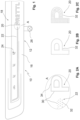
- Fig.1 illustrates, using a partial representation, an exemplary embodiment of a decorative component designated overall with 10.
- the decorative component 10 is designed as a panel component 12, for example for use in a vehicle.
- a door sill part of a door panel or as a control panel part on the dashboard or in the vicinity thereof is conceivable.
- the panel component 12 comprises a metal decorative layer 16, which is made from a thin sheet. It can be, for example, a steel sheet, an aluminum sheet or the like.
- the metal decorative layer 16 defines a surface of the decorative component 10 facing the user.
- the decorative component 10 has design elements 18 which are incorporated into the metal decorative layer 16.
- the design elements 18 are text or a label (design element 20), lines and similar patterns (design element 22), and symbols (design element 24).
- a light source designated 26 is indicated, which can be part of the decorative component 10 or at least coupled to it. Light can be coupled into a transparent/translucent light-conducting layer (hereinafter also referred to as carrier layer) of the decorative component 10 via the light source 26 in order to illuminate the design elements 18 from behind.
- carrier layer transparent/translucent light-conducting layer
- Fig. 2A shows an enlarged view of a section marked A from Fig.1 .
- the representation in Fig. 2A shows that the design elements 18 are formed by recesses 30 in the form of grid elements 32, 34.
- the design elements 18 are each formed by a plurality of small/filigree recesses 30 in the metal decorative layer 16, which form grid elements 32, 34.
- the recesses 30 can also be referred to as openings.
- the linear design element designated 22 is formed, for example, by a plurality of grid elements 32, which are designed as holes or bores. Fig. 2A It becomes apparent that holes of different sizes can be provided.
- the text-shaped design element designated 20 is formed, for example, by a plurality of grid elements 34 which are designed in the shape of a groove or slot.
- the grid elements 32, 34 formed by the recesses 30 are designed so delicately that the design elements 18 formed thereby on the metal decorative layer 16 are not or only barely visible when the design elements 18 are not actively backlit. Something like this is referred to as a disappearing effect.
- Fig. 2B and Fig. 2C show alternative possibilities for the grid-based generation of the text-like design element 20.
- the text-shaped design element 20 is formed by spaced-apart rows of grid elements 32 in the form of holes, which represent outlines of the design element 20.
- the text-shaped design element 20 is formed by a planar arrangement (matrix) of grid elements 32 in the form of holes, which represent the surface of the design element 20.
- the Fig. 2A, 2B, and 2C The grid elements 32, 34 shown are so delicate that the grid is not clearly visible/resolvable from a normal distance from which an operator looks at the design elements 18. Overall, this can result in a very high-quality aesthetic impression.
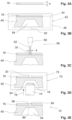
- Fig. 3A shows a sectional side view of a thin metal sheet that is intended to form a metal decorative layer 16.
- a thickness of the sheet is designated by h.
- the thickness h can be approximately 0.1 mm to 0.5 mm.
- the thickness h is 0.2 mm, 0.3 mm, or an intermediate value.
- the thickness h of the sheet is selected such that, at least with fleeting contact, the high thermal conductivity of the metal gives a user the impression of touching a metal component and not just a thin film.
- Fig. 3B illustrates, in addition to the metal decorative layer 16, a carrier layer 40 which consists of a plastic material.
- the carrier layer 40 is at least partially translucent and/or transparent, at least in sections. In other words, the carrier layer 40 is designed, at least in sections, to conduct light.
- Fig. 3B further illustrates a joining device 42, which can also be referred to as a joining tool.
- the joining device 42 is designed as an injection molding tool for processing thermoplastic materials.
- this is not to be understood as limiting.
- the joining device 42 has a first mold half 44 and a second mold half 46.
- the two mold halves 44, 46 define a cavity between them that can be filled with the thermoplastic material.
- the joining device 42 is designed as a back-injection device. In other words, the joining device 42 is designed to produce the carrier layer 40 by means of insert molding and to firmly connect it to the metal decorative layer 16 previously introduced into the mold half 44.
- Fig. 3B also shows a channel 50 for a sprue and a recess 54 in the carrier layer 40, which is defined by the design of the mold half 46. However, this is not to be understood as limiting.
- Fig. 3C illustrates a manufacturing step that takes place, at least in exemplary embodiments, when the back-injected component, comprising the metal decorative layer 16 and the carrier layer 40, has been removed from the joining device 42.
- Fig. 13 shows a metal processing device 58, which comprises a cutting tool 60.
- the cutting tool 60 can also be referred to as a drilling tool. For example, it is a laser cutting tool.
- the cutting tool 60 generates laser radiation 62. With this high-energy radiation, recesses/openings 30 can be introduced into the metal decorative layer 16.
- the cutting tool 60 does not necessarily have to be designed as a laser cutting tool. Other types of cutting tools are conceivable, provided that the desired filigree structures can be produced with these cutting tools. It is understood that a plurality of recesses 30 can be introduced into the metal decorative layer 16 using the metal processing device 58.
- the recess 30 shown as an example has a lateral extent d.
- the lateral extent d generally corresponds to a smallest lateral extent of the recess 30. If the recess 30 is a bore, the lateral extent d corresponds to the diameter of the bore.
- the lateral extent d is 0.1 mm to 0.5 mm, preferably 0.1 mm to 0.3 mm, more preferably 0.1 mm to 0.2 mm.
- the ratio of the thickness h of the metal decorative layer 16 and the lateral extent d of the recess 30 can also be referred to as the aspect ratio.
- the aspect ratio can have values of approximately 0.5:1 to 1.5:1.
- the aspect ratio is approximately 1:1.
- Such aspect ratios combined with the boundary condition that the design elements 18 on the metal decorative layer 16 are preferably in the unlit state due to the disappearing effect should be difficult or impossible to see, can lead to problems during production if it is desired that the recesses 30 are completely filled with the plastic material from which the carrier layer 40 is formed.
- the structures are so delicate that the plastic cannot simply penetrate completely and flush (relative to a front side of the decorative component 10) into the recesses 30 during injection molding.
- Fig.3D an embossing device 70, which can also be referred to as an embossing tool.
- the embossing device 70 comprises a counterholder 72, which supports the metal decorative layer 16 during embossing and further defines a target surface for the metal decorative layer 16 and the recesses 30 filled with the plastic material.
- the embossing is carried out, for example, by an embossing stamp 74, which acts from behind on the carrier layer 40 in order to force (softened) plastic material into the recesses 30.
- the embossing takes place in an at least partially softened state of the plastic material.
- the embossing device 70 is provided, for example, with a heating device 76, which in the Fig.3D shown embodiment is provided at the stamping die 74.
- An arrow marked 78 illustrates a movement of the stamping die 74.
- Fig. 3E illustrates a state after embossing, in which the recesses 30 of the metal decorative layer 16 are filled flush with the plastic material in the desired manner, compare the reference number 84, which shows the filling.
- the embossing stamp 74 has created a depression 86 in the carrier layer 40 (in addition to the depression 54).
- a flat and flush (frontal) surface 88 can thus be created for the metal decorative layer 16 and consequently for the decorative component 10.
- the decorative component 10 is provided with a light source (see Fig.1 ) or coupled.
- the carrier layer then acts as a light guide to the recesses 30.
- FIG. 4A to 4D A further exemplary sequence of a method for producing a backlit decorative component 10 is shown using schematic, highly simplified partial views (compare the illustration in Fig.1 ) is illustrated.
- the Figures 4A to 4D The procedure illustrated differs from that in the Figures 3A to 3E shown method on the one hand in that the recesses 30 are introduced into the metal decorative layer 16 by the metal processing device 58 even when this has not yet been joined to the carrier layer 40, compare also Fig. 4A .
- the metal processing device 58 is designed as a laser processing device and is provided with a cutting tool/drilling tool 60 which has a laser for generating laser radiation 62.
- the metal decorative layer 16 has a thickness h. Furthermore, the recesses 30 have a (smallest) lateral extension d.
- the extension d can be a diameter if the recesses 30 are designed as bores/circular holes.
- the recesses 30 are designed in a filigree manner and allow the formation of gridded design elements 18, see also Fig.1 .
- Fig. 4B illustrates a joining device designated 92, which is designed to laminate the metal decorative layer 16 with the provided carrier layer 40.
- the carrier layer 40 can be produced and processed beforehand in an injection molding process, an extrusion process, a thermoforming process or in some other way.
- the lamination can bring about a material-locking joining between the metal decorative layer 16 and the carrier layer 40.
- Lamination may include bonding the metal decorative layer 16 and the carrier layer 40.
- Other operating principles are conceivable.
- the joining device 92 has a first holder 94 and a second holder 96.
- the metal decorative layer 16 with the recesses 30 is accommodated on the first holder 94.
- the carrier layer 40 is accommodated on the second holder 96.
- a dashed representation illustrates a joining layer 100, which can be provided in addition to the carrier layer 40 and the metal decorative layer 16.
- the joining layer 100 serves to promote adhesion between the carrier layer 40 and the metal decorative layer 16.
- Lamination can be carried out by applying pressure and/or heat. Movement of the two holders 94, 96 is illustrated by arrows marked 102, 104.
- Fig. 4C illustrates that an embossing device 70 is provided for this purpose, which has a counterholder 72 and an embossing stamp 74.
- the embossing stamp 74 has a heating device 76.
- An arrow designated 78 illustrates the movement of the embossing stamp 74 during embossing, wherein the embossing stamp 74 moves into a recess 54 of the carrier layer 40 in order to displace softened material there, which should then close the recesses 40 flush.
- an embossing stamp 74 can be assigned to a single recess 30, but also to a plurality of recesses 30. Since the recesses 30 are preferably designed in a filigree manner and have small lateral minimum dimensions, it is conceivable to fill a plurality or even a multiplicity of recesses 30 by means of embossing with a single embossing stamp 74.
- Fig. 4D illustrates the decorative component 10 in the joined state.
- Plastic material of the carrier layer 40 was forced into the recesses 30 of the metal decorative layer 16 in order to form a filling 84 there.
- the surface 88 of the decorative component 10 or the metal decorative layer 16 preferably has a smooth and flush design.
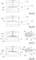
- FIG. 5A to 5D A further exemplary sequence of a method for producing a backlit decorative component 10 is shown using schematic, highly simplified partial views (compare the illustration in Fig.1 ) is illustrated.
- the aim is to provide a decorative component 10 which has a metal decorative layer 16 and a carrier layer 40 which are joined together, wherein the metal decorative layer 16 is provided with a plurality of recesses 30, and wherein plastic material of the carrier layer 40 fills these recesses 30 flush.
- an injection-compression molding device 112 is used on the one hand to back-inject the metal decorative layer 16 and on the other hand to carry out the embossing process for flush filling the recesses 30.
- the injection-compression molding device 112 can also be referred to as a combined injection and embossing tool.
- the injection-compression molding device 112 has a first mold half 114 and a second mold half 116.
- a receptacle 118 for receiving the metal decorative layer 16 is formed in the second mold half 116. Accordingly, the metal decorative layer 16 can be placed as an insert in the tool of the injection-compression molding device 112 and back-injected there.
- a channel 120 is formed through which the injection molding compound (melt) can penetrate into the cavity defined by the two mold halves 114, 116.
- Fig. 5A shows a state in which the two mold halves 114 and 116 are opened and in which the metal decorative layer 16 is not yet received in the receptacle 118.
- the metal decorative layer 16 is arranged in the receptacle 118.
- the mold halves 114, 116 are partially, but not yet completely closed.
- An embossing gap a remains between the two mold halves 114, 116.
- the two mold halves 114, 116 are not yet in their completely closed position (compare Fig. 5D ). Accordingly, the cavity that can be moved with the injection molding material is slightly larger than the cavity for the carrier layer 40, which is defined in the completely closed state of the two mold halves 114, 116.
- Fig. 5C illustrates an injection molding process. Injection molding compound is injected through the channel 120 and forms a sprue 122. The cavity between the two mold halves 114, 116 is filled with the injection molding material.
- the detail B in Fig. 5C illustrates on the one hand a (temporary) thickness t1 of the carrier layer 40. Furthermore, detail B in Fig. 5C that the recess 30 is partially but not completely filled during the injection molding process. The partial filling is designated 124. If the flow fronts solidify quickly there, which is often to be expected, then it is not possible to completely fill the recess 30 by an injection molding process.
- the aspect ratio of the recess 30 is quite low primarily for illustrative purposes and thus does not necessarily correspond to the target ranges for the aspect ratio, which within the scope of the present disclosure is also intended to be made possible with complete filling by the plastic material.
- the injection molding process illustrated is followed by a stamping process.
- Fig. 5D the embossing process follows with a certain time offset from the injection molding process, so that the material forming the carrier layer 40 is still sufficiently soft to be able to be completely and flush introduced into the recess 30 by embossing.
- an arrow marked 126 illustrates the corresponding relative movement between the first mold half 114 and the second mold half 116.
- the detail C in Fig. 5D further shows that the carrier layer 40 now has a (final) thickness t2 which is smaller than the (temporary) thickness t1.
- detail C shows that the recess 30 is completely filled, the reference number 84 shows the filling.
- the surface 88 of the metal decorative layer 16 or of the decorative component 10 provided with it is smooth and flush.
- Fig.6 shows a system 130 that is provided with a joining device 132, which can also be referred to as an injection molding device.
- the joining device 132 has a mold 134, which can also be referred to as an injection mold or injection molding tool.
- the joining device 132 is designed for back-injection molding of a metal decorative layer 16, which can be placed in the mold 134.
- a carrier layer 40 is formed by the back-injection molding.
- An arrow labeled 136 illustrates the supply of the melt via a channel 138.
- a back-injected composite body can be designed that includes the metal decorative layer 16 and the carrier layer 14.
- the system 130 further comprises a metalworking device 140, which comprises a metalworking tool 142.
- a metalworking tool 142 With the metalworking tool 142, recesses 30 can be made in the metal decorative layer 16. This is done according to the Fig.6 illustrated embodiment, for example, in a state in which the metal decorative layer 16 is already joined to the carrier layer 40. However, this is not to be understood as limiting.
- the system 130 has an embossing device designated 146, which can also be referred to as an embossing tool.
- the embossing device 146 has an embossing stamp 148, which is provided with a heating unit 150 for at least partially softening the carrier layer 40.
- the Fig.6 The embossing stamp 148 shown is adapted, by way of example, to a plurality of recesses 30 in the metal decorative layer 16 in order to introduce the softened plastic material of the carrier layer 40 into the recesses 30 in order to fill them as flush as possible.
- An arrow designated 152 illustrates the movement of the embossing stamp 148.
- the embossing stamp 148 displaces material and pushes it into the recesses 30 of the metal decorative layer 16.
- a depression 86 remains on the back of the carrier layer 40.
- Fig.7 illustrates a basically similarly designed system 160, which is also designed to produce a decorative component 10 with a metal decorative layer 16 and a carrier layer 40.
- the system 160 has a metal processing device 162 which is provided with a metal processing tool 164.
- the metal processing device 162 is designed to produce a plurality or multiplicity of small recesses 30 in the metal decorative layer 16, specifically in a state in which the metal decorative layer 16 is not yet joined to the carrier layer 40. In other words, the metal processing device 162 can produce a perforated thin sheet/fine sheet of small thickness.
- the system 160 further comprises a joining device 170, which is designed, for example, to produce a composite of the metal decorative layer 16 and the carrier layer 40 by lamination.
- the joining device 170 can therefore also be referred to as a laminating device.
- the joining process or the joining movement in the joining device 170 are described in Fig.7 by designated 172, 174 Arrows illustrated.
- Laminating may include bonding the metal decorative layer 16 to the carrier layer 40.
- the embossing device 178 has an embossing stamp 180, which is provided with a heating unit 182 for at least partially softening the carrier layer 40.
- the embossing stamp 180 shown is adapted, by way of example, to a plurality of recesses 30 in the metal decorative layer 16 in order to introduce the softened plastic material of the carrier layer 40 into the recesses 30 in order to fill them as flush as possible.
- An arrow designated 184 illustrates the movement of the embossing stamp 180.
- the embossing stamp 180 displaces material and pushes it into the recesses 30 of the metal decorative layer 16.
- a depression 86 remains on the back of the carrier layer 40.
- FIG.8 An exemplary embodiment of a method for producing a decorative component, in particular for producing a panel component, is illustrated using a schematic block diagram.
- the method comprises a first step S10, which comprises the provision of a metal decorative layer made of a thin sheet or a thin metal sheet. This is followed by a step S12, which concerns the creation of holes/recesses/perforations in the metal decorative layer.
- the recesses are preferably designed in such a filigree manner that a so-called disappearing effect occurs during operation of the metal decorative layer when design elements that are defined by the recesses and can be illuminated become invisible or almost invisible to an observer from a certain distance when the lighting of the design elements is deactivated.
- step S14 the metal decorative layer is joined to a carrier layer.
- step S14 can comprise a material-to-material joining.
- the joining can comprise back-injection molding of the metal decorative layer, which also includes the production of the carrier layer by means of injection molding.
- the joining can also comprise laminating/gluing the metal decorative layer to the carrier layer.
- the carrier layer is preferably made of a plastic material. In particular, this can be a plastic material that is at least partially transparent and/or translucent.
- the carrier layer can also have other components in addition to the at least partially transparent and/or translucent plastic material.
- the carrier layer does not have to consist entirely of the at least partially transparent and/or translucent plastic material.
- a further subsequent step S16 relates to an embossing process.
- the embossing process aims to displace the plastic material that forms the carrier layer, at least in sections, in an at least partially softened state in such a way that the recesses in the metal decorative layer are filled securely and flush with the plastic material.
- the embossing takes place in an embossing device or with an embossing stamp, which are provided with a heating device for softening the plastic.
- steps S14 and S16 for example in a combined injection-compression molding process in one injection-compression molding tool.
- the Fig.9 The method shown comprises steps S20, S22, S24, and S26.
- the step S20 relates similarly to the step S10 in Fig.8 the provision of a metal decorative layer from a thin sheet or sheet.
- Step S22 relates to the joining of the metal decorative layer to a carrier layer.
- the joining process takes place in a state of the metal decorative layer in which it is not yet provided with the recesses.
- step S22 can also include a back-injection process, a laminating process or the like.
- the joining preferably includes a liquid joining process.
- the carrier layer consists at least partially of an at least partially transparent and/or translucent plastic material.
- recesses are made in the metal decorative layer when the metal decorative layer is joined to the carrier layer. These are preferably filigree recesses in the form of holes, openings, grooves, etc. A plurality/multiplicity of recesses are combined with one another in order to form gridded design elements on the metal decorative layer.
Landscapes
- Engineering & Computer Science (AREA)
- Mechanical Engineering (AREA)
- Manufacturing & Machinery (AREA)
- Injection Moulding Of Plastics Or The Like (AREA)
- Laminated Bodies (AREA)
Claims (11)
- Procédé permettant la fabrication d'un composant de décoration (10) pouvant être rétroéclairé, en particulier d'un composant formant panneau (12), comportant les étapes suivantes :- fourniture d'une couche de décoration métallique (16) en une tôle fine, en particulier en une tôle mince,- assemblage de la couche de décoration métallique (16) avec une couche de support (40) en une matière plastique,dans lequel la couche de support (40) est au moins partiellement transparente ou translucide, etdans lequel la couche de support (40) forme, à l'état assemblé, une couche arrière derrière la couche de décoration métallique (16), et- gaufrage, au moins dans certaines sections, de la couche de support (40) dans un état au moins partiellement ramolli de la matière plastique, afin de remplir de matière plastique une pluralité d'évidements (30) dans la couche de décoration métallique (16) en partant de la couche de support (40) arrière,caractérisé en ce queles évidements (30) remplis de matière plastique constituent des éléments d'encadrement (32, 34), en particulier des points d'image, qui, en combinaison, forment au moins un élément de configuration (18) encadré et rétroéclairé du composant de décoration (10), etles évidements (30) remplis de matière plastique sont remplis en affleurement de matière plastique.
- Procédé selon la revendication 1, présentant en outre :- la production des évidements (30) dans la couche de décoration métallique (16), dans lequel au moins certains des évidements (30) présentent une extension latérale (d) inférieure à 0,3 mm, de préférence inférieure à 0,2 mm.
- Procédé selon la revendication 1 ou 2, dans lequel la couche de décoration métallique (16) présente une épaisseur de tôle (h) dans la plage allant de 0,05 mm à 0,5 mm, de préférence dans la plage allant de 0,1 mm à 0,3 mm.
- Procédé selon l'une des revendications 1 à 3, dans lequel un rapport d'aspect d'au moins certains des évidements (30) de la couche de décoration métallique (16) se situe dans la plage allant de 0,5:1 à 1,5:1, de préférence est d'environ 1:1.
- Procédé selon l'une des revendications 1 à 4, dans lequel au moins certains des évidements (30) sont produits par un usinage au laser.
- Procédé selon l'une des revendications 1 à 5, dans lequel au moins certains des évidements (30) sont produits dans la couche de décoration métallique (16) avant que la couche de décoration métallique (16) ne soit assemblée avec la couche de support (40).
- Procédé selon l'une des revendications 1 à 5, dans lequel au moins certains des évidements (30) sont produits dans la couche de décoration métallique (16) après que la couche de décoration métallique (16) a été assemblée avec la couche de support (40).
- Procédé selon l'une des revendications 1 à 7, dans lequel l'assemblage de la couche de décoration métallique (16) avec la couche de support (40) et le gaufrage de la couche de support (40) sont effectués dans un processus de moulage par injection-gaufrage, de préférence dans un outil combiné de moulage par injection et de gaufrage (112).
- Procédé selon l'une des revendications 1 à 7, dans lequel le gaufrage de la couche de support (40) est effectué dans un processus de thermo-gaufrage, dans lequel la matière plastique est ramollie au moins dans certaines sections par apport de chaleur dans un outil de gaufrage (70, 146, 178).
- Procédé selon la revendication 9, dans lequel un processus de moulage par injection précède le processus de gaufrage pour la production de la couche de support (40) et pour l'assemblage de la couche de décoration métallique (16) avec la couche de support (40).
- Procédé selon la revendication 9, dans lequel un processus de laminage précède le processus de gaufrage pour l'assemblage de la couche de décoration métallique (16) avec la couche de support (40).
Applications Claiming Priority (2)
| Application Number | Priority Date | Filing Date | Title |
|---|---|---|---|
| DE102018113194.1A DE102018113194A1 (de) | 2018-06-04 | 2018-06-04 | Verfahren und Anlage zur Herstellung eines Dekorbauteils, sowie Dekorbauteil |
| PCT/EP2019/064494 WO2019234023A1 (fr) | 2018-06-04 | 2019-06-04 | Procédé et installation de fabrication d'un composant décoratif et composant décoratif |
Publications (2)
| Publication Number | Publication Date |
|---|---|
| EP3802048A1 EP3802048A1 (fr) | 2021-04-14 |
| EP3802048B1 true EP3802048B1 (fr) | 2024-09-18 |
Family
ID=66867103
Family Applications (1)
| Application Number | Title | Priority Date | Filing Date |
|---|---|---|---|
| EP19730714.3A Active EP3802048B1 (fr) | 2018-06-04 | 2019-06-04 | Procédé et installation de fabrication d'un composant décoratif et composant décoratif |
Country Status (3)
| Country | Link |
|---|---|
| EP (1) | EP3802048B1 (fr) |
| DE (1) | DE102018113194A1 (fr) |
| WO (1) | WO2019234023A1 (fr) |
Families Citing this family (8)
| Publication number | Priority date | Publication date | Assignee | Title |
|---|---|---|---|---|
| DE102018113194A1 (de) | 2018-06-04 | 2019-12-05 | Rolf Prettl | Verfahren und Anlage zur Herstellung eines Dekorbauteils, sowie Dekorbauteil |
| EP4140812B1 (fr) * | 2021-08-24 | 2024-01-10 | Grupo Antolin-Ingenieria, S.A. | Habillage de pièces intérieures de véhicule rétroéclairés, procédé et installation pour sa fabrication |
| DE102022103620A1 (de) * | 2022-02-16 | 2023-08-17 | Lisa Dräxlmaier GmbH | Verfahren zum herstellen eines eine funktionsöffnung aufweisenden dekorelements für ein kraftfahrzeug sowie dekorelement |
| DE102022103619A1 (de) * | 2022-02-16 | 2023-08-17 | Lisa Dräxlmaier GmbH | Verfahren zum herstellen eines eine funktionsöffnung aufweisenden dekorelements für ein kraftfahrzeug sowie dekorelement |
| DE102022104306A1 (de) * | 2022-02-23 | 2023-08-24 | Novem Car Interior Design Gmbh | Formteil und Verfahren zur Herstellung eines Formteils |
| DE102022104308B4 (de) | 2022-02-23 | 2023-11-30 | Novem Car Interior Design Gmbh | Formteil und Verfahren zur Herstellung eines Formteils |
| DE102022005006A1 (de) | 2022-02-23 | 2023-08-24 | Novem Car Interior Design Gmbh | Formteil und Verfahren zur Herstellung eines Formteils |
| EP4496731A4 (fr) * | 2022-03-22 | 2025-06-25 | Gentex Corporation | Ensemble rétroviseur d'affichage complet doté d'éclairage infrarouge à collerette d'encastrement traversante |
Citations (1)
| Publication number | Priority date | Publication date | Assignee | Title |
|---|---|---|---|---|
| WO2012001146A1 (fr) * | 2010-07-02 | 2012-01-05 | Kunststoff-Technik Scherer & Trier Gmbh & Co Kg | Procédé de fabrication d'une pièce moulée et pièce moulée |
Family Cites Families (17)
| Publication number | Priority date | Publication date | Assignee | Title |
|---|---|---|---|---|
| IT1261085B (it) | 1993-07-06 | 1996-05-08 | Procedimento di inietto-compressione per la realizzazione di articoli di forma complessa in materiale elastomerico. | |
| JPH0788886A (ja) * | 1993-09-24 | 1995-04-04 | Nifco Inc | 加飾品の製造方法 |
| JPH11262964A (ja) * | 1998-03-16 | 1999-09-28 | Komatsu Ltd | プラスチック積層体およびその製造方法 |
| US6652128B2 (en) * | 2001-01-31 | 2003-11-25 | Textron Automotive Company, Inc. | Backlighting method for an automotive trim panel |
| CA2366480A1 (fr) * | 2002-01-02 | 2003-07-02 | Arai Katsuo | Plaque d'immatriculation adaptee pour eclairage interne |
| DE10350612A1 (de) * | 2003-10-30 | 2005-06-09 | Siemens Ag | Verfahren zur Herstellung eines mindestens ein hinterleuchtbares Symbol aufweisenden Anzeigefeldes |
| US20070290411A1 (en) * | 2004-11-08 | 2007-12-20 | Hans Suter | Method For Producing A Composite Part By Injection Moulding, Injection Compression Moulding Or Back Compression Moulding Of A Plastic Material |
| DE202009011157U1 (de) | 2009-08-18 | 2011-01-05 | Wiese, Reinhard | Glasplatte, insbesondere Mehrscheiben-Verbundglasplatte |
| EP2295293B2 (fr) * | 2009-09-11 | 2019-02-20 | Weidplas GmbH | Procédé de fabrication d'un composant doté d'un élément décoratif plat et composant doté d'un élément décoratif plat |
| DE102011012789A1 (de) | 2011-03-02 | 2012-09-06 | Audi Ag | Innenverkleidungsteil für ein Kraftfahrzeug |
| US9812042B2 (en) * | 2012-10-29 | 2017-11-07 | Innotec Corp. | Lighted trim assembly and perforated member therefor |
| DE102013202223B4 (de) | 2013-02-12 | 2019-06-13 | Lisa Dräxlmaier GmbH | Verfahren zur Herstellung eines Dekorverbunds durch Umformen von Folie an Materialöffnungen mittels eines Laser- und/oder Warmluftstrahls |
| JP6510208B2 (ja) * | 2014-09-30 | 2019-05-08 | ヤマハファインテック株式会社 | 加飾パネル及び加飾パネルの製造方法 |
| DE102015006566B4 (de) * | 2015-05-21 | 2022-03-03 | Audi Ag | Verfahren zum Bereitstellen einer eine Symbolik aufweisenden Oberfläche eines Bauteils |
| JP6801966B2 (ja) * | 2016-02-05 | 2020-12-16 | ヤマハファインテック株式会社 | 装飾パネル及びその製造方法 |
| FR3069805B1 (fr) * | 2017-08-02 | 2021-01-08 | Reydel Automotive Bv | Procede de revetement d'un support courbe avec un materiau rigide et panneau d'habillage obtenu par ce procede |
| DE102018113194A1 (de) | 2018-06-04 | 2019-12-05 | Rolf Prettl | Verfahren und Anlage zur Herstellung eines Dekorbauteils, sowie Dekorbauteil |
-
2018
- 2018-06-04 DE DE102018113194.1A patent/DE102018113194A1/de not_active Withdrawn
-
2019
- 2019-06-04 EP EP19730714.3A patent/EP3802048B1/fr active Active
- 2019-06-04 WO PCT/EP2019/064494 patent/WO2019234023A1/fr not_active Ceased
Patent Citations (1)
| Publication number | Priority date | Publication date | Assignee | Title |
|---|---|---|---|---|
| WO2012001146A1 (fr) * | 2010-07-02 | 2012-01-05 | Kunststoff-Technik Scherer & Trier Gmbh & Co Kg | Procédé de fabrication d'une pièce moulée et pièce moulée |
Also Published As
| Publication number | Publication date |
|---|---|
| EP3802048A1 (fr) | 2021-04-14 |
| WO2019234023A1 (fr) | 2019-12-12 |
| DE102018113194A1 (de) | 2019-12-05 |
Similar Documents
| Publication | Publication Date | Title |
|---|---|---|
| EP3802048B1 (fr) | Procédé et installation de fabrication d'un composant décoratif et composant décoratif | |
| EP2295293B1 (fr) | Procédé de fabrication d'un composant doté d'un élément décoratif plat et composant doté d'un élément décoratif plat | |
| EP2529912B1 (fr) | Support fonctionnel avec fonctions de touches | |
| DE102014112470B4 (de) | Ausstattungsteil mit leuchtender sichtseite | |
| EP2803463A1 (fr) | Support fonctionnel avec fonctions de touches | |
| EP2942233B1 (fr) | Élément d'éclairage plat pour l'équipement intérieur d'un véhicule | |
| DE102004054228A1 (de) | Verfahren und Vorrichtung zur Herstellung eines Verbundteils | |
| EP3517271B1 (fr) | Procédé de fabrication d'une pièce moulée dotée d'une surface visible pourvue de différentes zones de surface | |
| DE102015105974A1 (de) | Ausstattungsteil für ein Kraftfahrzeug | |
| EP1621313A1 (fr) | Procédé et appareil pour produire une pièce décorée avec un symbole exposé et pièce décorée ainsi produite | |
| DE4337697C1 (de) | Verfahren zur Herstellung von formstabilen, kaschierten Formteilen, wie Innenverkleidungen von Kraftfahrzeugen | |
| DE102015003448A1 (de) | Zierteil, Dekorteil und Verfahren zur Herstellung eines Zierteils | |
| DE102007057934A1 (de) | Verfahren zum Herstellen eines auf zumindest einer Fläche kunststoffbeschichteten metallischen Bauteils | |
| EP3615369B1 (fr) | Partie visible, notamment pour un élément de commande dans un véhicule automobile | |
| EP1542847B1 (fr) | Procede pour fabriquer un produit et produit fabrique selon ce procede | |
| DE102005023440A1 (de) | Anzeige- und/oder Bedienungspaneel | |
| EP4043176B1 (fr) | Procédé de fabrication d'une pièce décorative pour un habitacle de véhicule | |
| DE102020100992B4 (de) | Verfahren zur Herstellung eines abschnittsweise durchleuchtbaren Schichtverbundes, abschnittsweise durchleuchtbarer Schichtverbund, Verfahren zur Herstellung eines Interieurbauteils und damit hergestelltes Interieurbauteil | |
| DE102013014420A1 (de) | Verfahren zur Herstellung eines Dekorteils und nach diesem Verfahren hergestelltes Dekorteil | |
| EP2604406B1 (fr) | Procédé de fabrication d'un produit | |
| DE102021107693B4 (de) | Formteil und Verfahren zur Herstellung eines Formteils | |
| DE102011116838A1 (de) | Dekorgewebe | |
| DE102021006588A1 (de) | Formteil und Verfahren zur Herstellung eines Formteils | |
| DE102015006566A1 (de) | Verfahren zum Bereitstellen einer eine Symbolik aufweisenden Oberfläche eines Bauteils | |
| EP3722065A1 (fr) | Pièce de garniture de véhicule automobile et son procédé de fabrication |
Legal Events
| Date | Code | Title | Description |
|---|---|---|---|
| STAA | Information on the status of an ep patent application or granted ep patent |
Free format text: STATUS: UNKNOWN |
|
| STAA | Information on the status of an ep patent application or granted ep patent |
Free format text: STATUS: THE INTERNATIONAL PUBLICATION HAS BEEN MADE |
|
| PUAI | Public reference made under article 153(3) epc to a published international application that has entered the european phase |
Free format text: ORIGINAL CODE: 0009012 |
|
| STAA | Information on the status of an ep patent application or granted ep patent |
Free format text: STATUS: REQUEST FOR EXAMINATION WAS MADE |
|
| 17P | Request for examination filed |
Effective date: 20201218 |
|
| AK | Designated contracting states |
Kind code of ref document: A1 Designated state(s): AL AT BE BG CH CY CZ DE DK EE ES FI FR GB GR HR HU IE IS IT LI LT LU LV MC MK MT NL NO PL PT RO RS SE SI SK SM TR |
|
| AX | Request for extension of the european patent |
Extension state: BA ME |
|
| TPAC | Observations filed by third parties |
Free format text: ORIGINAL CODE: EPIDOSNTIPA |
|
| DAV | Request for validation of the european patent (deleted) | ||
| DAX | Request for extension of the european patent (deleted) | ||
| STAA | Information on the status of an ep patent application or granted ep patent |
Free format text: STATUS: EXAMINATION IS IN PROGRESS |
|
| 17Q | First examination report despatched |
Effective date: 20221102 |
|
| GRAP | Despatch of communication of intention to grant a patent |
Free format text: ORIGINAL CODE: EPIDOSNIGR1 |
|
| STAA | Information on the status of an ep patent application or granted ep patent |
Free format text: STATUS: GRANT OF PATENT IS INTENDED |
|
| RIC1 | Information provided on ipc code assigned before grant |
Ipc: B29L 9/00 20060101ALN20240311BHEP Ipc: B29C 43/52 20060101ALN20240311BHEP Ipc: B29L 31/00 20060101ALN20240311BHEP Ipc: B29K 705/00 20060101ALN20240311BHEP Ipc: B29C 43/36 20060101ALI20240311BHEP Ipc: B60R 13/02 20060101ALI20240311BHEP Ipc: B32B 38/06 20060101ALI20240311BHEP Ipc: B29C 45/00 20060101ALI20240311BHEP Ipc: B32B 38/04 20060101ALI20240311BHEP Ipc: B29C 45/56 20060101ALI20240311BHEP Ipc: B29C 45/14 20060101AFI20240311BHEP |
|
| RIC1 | Information provided on ipc code assigned before grant |
Ipc: B29L 9/00 20060101ALN20240318BHEP Ipc: B29C 43/52 20060101ALN20240318BHEP Ipc: B29L 31/00 20060101ALN20240318BHEP Ipc: B29K 705/00 20060101ALN20240318BHEP Ipc: B29C 43/36 20060101ALI20240318BHEP Ipc: B60R 13/02 20060101ALI20240318BHEP Ipc: B32B 38/06 20060101ALI20240318BHEP Ipc: B29C 45/00 20060101ALI20240318BHEP Ipc: B32B 38/04 20060101ALI20240318BHEP Ipc: B29C 45/56 20060101ALI20240318BHEP Ipc: B29C 45/14 20060101AFI20240318BHEP |
|
| INTG | Intention to grant announced |
Effective date: 20240410 |
|
| GRAS | Grant fee paid |
Free format text: ORIGINAL CODE: EPIDOSNIGR3 |
|
| GRAA | (expected) grant |
Free format text: ORIGINAL CODE: 0009210 |
|
| STAA | Information on the status of an ep patent application or granted ep patent |
Free format text: STATUS: THE PATENT HAS BEEN GRANTED |
|
| AK | Designated contracting states |
Kind code of ref document: B1 Designated state(s): AL AT BE BG CH CY CZ DE DK EE ES FI FR GB GR HR HU IE IS IT LI LT LU LV MC MK MT NL NO PL PT RO RS SE SI SK SM TR |
|
| REG | Reference to a national code |
Ref country code: GB Ref legal event code: FG4D Free format text: NOT ENGLISH |
|
| REG | Reference to a national code |
Ref country code: CH Ref legal event code: EP |
|
| REG | Reference to a national code |
Ref country code: IE Ref legal event code: FG4D Free format text: LANGUAGE OF EP DOCUMENT: GERMAN |
|
| REG | Reference to a national code |
Ref country code: DE Ref legal event code: R096 Ref document number: 502019012156 Country of ref document: DE |
|
| REG | Reference to a national code |
Ref country code: LT Ref legal event code: MG9D |
|
| PG25 | Lapsed in a contracting state [announced via postgrant information from national office to epo] |
Ref country code: NO Free format text: LAPSE BECAUSE OF FAILURE TO SUBMIT A TRANSLATION OF THE DESCRIPTION OR TO PAY THE FEE WITHIN THE PRESCRIBED TIME-LIMIT Effective date: 20241218 |
|
| PG25 | Lapsed in a contracting state [announced via postgrant information from national office to epo] |
Ref country code: GR Free format text: LAPSE BECAUSE OF FAILURE TO SUBMIT A TRANSLATION OF THE DESCRIPTION OR TO PAY THE FEE WITHIN THE PRESCRIBED TIME-LIMIT Effective date: 20241219 Ref country code: FI Free format text: LAPSE BECAUSE OF FAILURE TO SUBMIT A TRANSLATION OF THE DESCRIPTION OR TO PAY THE FEE WITHIN THE PRESCRIBED TIME-LIMIT Effective date: 20240918 |
|
| PG25 | Lapsed in a contracting state [announced via postgrant information from national office to epo] |
Ref country code: BG Free format text: LAPSE BECAUSE OF FAILURE TO SUBMIT A TRANSLATION OF THE DESCRIPTION OR TO PAY THE FEE WITHIN THE PRESCRIBED TIME-LIMIT Effective date: 20240918 |
|
| PG25 | Lapsed in a contracting state [announced via postgrant information from national office to epo] |
Ref country code: LV Free format text: LAPSE BECAUSE OF FAILURE TO SUBMIT A TRANSLATION OF THE DESCRIPTION OR TO PAY THE FEE WITHIN THE PRESCRIBED TIME-LIMIT Effective date: 20240918 |
|
| PG25 | Lapsed in a contracting state [announced via postgrant information from national office to epo] |
Ref country code: HR Free format text: LAPSE BECAUSE OF FAILURE TO SUBMIT A TRANSLATION OF THE DESCRIPTION OR TO PAY THE FEE WITHIN THE PRESCRIBED TIME-LIMIT Effective date: 20240918 |
|
| REG | Reference to a national code |
Ref country code: NL Ref legal event code: MP Effective date: 20240918 |
|
| PG25 | Lapsed in a contracting state [announced via postgrant information from national office to epo] |
Ref country code: RS Free format text: LAPSE BECAUSE OF FAILURE TO SUBMIT A TRANSLATION OF THE DESCRIPTION OR TO PAY THE FEE WITHIN THE PRESCRIBED TIME-LIMIT Effective date: 20241218 |
|
| PG25 | Lapsed in a contracting state [announced via postgrant information from national office to epo] |
Ref country code: RS Free format text: LAPSE BECAUSE OF FAILURE TO SUBMIT A TRANSLATION OF THE DESCRIPTION OR TO PAY THE FEE WITHIN THE PRESCRIBED TIME-LIMIT Effective date: 20241218 Ref country code: NO Free format text: LAPSE BECAUSE OF FAILURE TO SUBMIT A TRANSLATION OF THE DESCRIPTION OR TO PAY THE FEE WITHIN THE PRESCRIBED TIME-LIMIT Effective date: 20241218 Ref country code: LV Free format text: LAPSE BECAUSE OF FAILURE TO SUBMIT A TRANSLATION OF THE DESCRIPTION OR TO PAY THE FEE WITHIN THE PRESCRIBED TIME-LIMIT Effective date: 20240918 Ref country code: HR Free format text: LAPSE BECAUSE OF FAILURE TO SUBMIT A TRANSLATION OF THE DESCRIPTION OR TO PAY THE FEE WITHIN THE PRESCRIBED TIME-LIMIT Effective date: 20240918 Ref country code: GR Free format text: LAPSE BECAUSE OF FAILURE TO SUBMIT A TRANSLATION OF THE DESCRIPTION OR TO PAY THE FEE WITHIN THE PRESCRIBED TIME-LIMIT Effective date: 20241219 Ref country code: FI Free format text: LAPSE BECAUSE OF FAILURE TO SUBMIT A TRANSLATION OF THE DESCRIPTION OR TO PAY THE FEE WITHIN THE PRESCRIBED TIME-LIMIT Effective date: 20240918 Ref country code: BG Free format text: LAPSE BECAUSE OF FAILURE TO SUBMIT A TRANSLATION OF THE DESCRIPTION OR TO PAY THE FEE WITHIN THE PRESCRIBED TIME-LIMIT Effective date: 20240918 |
|
| PG25 | Lapsed in a contracting state [announced via postgrant information from national office to epo] |
Ref country code: NL Free format text: LAPSE BECAUSE OF FAILURE TO SUBMIT A TRANSLATION OF THE DESCRIPTION OR TO PAY THE FEE WITHIN THE PRESCRIBED TIME-LIMIT Effective date: 20240918 |
|
| PG25 | Lapsed in a contracting state [announced via postgrant information from national office to epo] |
Ref country code: IS Free format text: LAPSE BECAUSE OF FAILURE TO SUBMIT A TRANSLATION OF THE DESCRIPTION OR TO PAY THE FEE WITHIN THE PRESCRIBED TIME-LIMIT Effective date: 20250118 Ref country code: PT Free format text: LAPSE BECAUSE OF FAILURE TO SUBMIT A TRANSLATION OF THE DESCRIPTION OR TO PAY THE FEE WITHIN THE PRESCRIBED TIME-LIMIT Effective date: 20250120 |
|
| PG25 | Lapsed in a contracting state [announced via postgrant information from national office to epo] |
Ref country code: SM Free format text: LAPSE BECAUSE OF FAILURE TO SUBMIT A TRANSLATION OF THE DESCRIPTION OR TO PAY THE FEE WITHIN THE PRESCRIBED TIME-LIMIT Effective date: 20240918 Ref country code: RO Free format text: LAPSE BECAUSE OF FAILURE TO SUBMIT A TRANSLATION OF THE DESCRIPTION OR TO PAY THE FEE WITHIN THE PRESCRIBED TIME-LIMIT Effective date: 20240918 |
|
| PG25 | Lapsed in a contracting state [announced via postgrant information from national office to epo] |
Ref country code: ES Free format text: LAPSE BECAUSE OF FAILURE TO SUBMIT A TRANSLATION OF THE DESCRIPTION OR TO PAY THE FEE WITHIN THE PRESCRIBED TIME-LIMIT Effective date: 20240918 |
|
| PG25 | Lapsed in a contracting state [announced via postgrant information from national office to epo] |
Ref country code: EE Free format text: LAPSE BECAUSE OF FAILURE TO SUBMIT A TRANSLATION OF THE DESCRIPTION OR TO PAY THE FEE WITHIN THE PRESCRIBED TIME-LIMIT Effective date: 20240918 |
|
| PG25 | Lapsed in a contracting state [announced via postgrant information from national office to epo] |
Ref country code: CZ Free format text: LAPSE BECAUSE OF FAILURE TO SUBMIT A TRANSLATION OF THE DESCRIPTION OR TO PAY THE FEE WITHIN THE PRESCRIBED TIME-LIMIT Effective date: 20240918 Ref country code: PL Free format text: LAPSE BECAUSE OF FAILURE TO SUBMIT A TRANSLATION OF THE DESCRIPTION OR TO PAY THE FEE WITHIN THE PRESCRIBED TIME-LIMIT Effective date: 20240918 |
|
| PG25 | Lapsed in a contracting state [announced via postgrant information from national office to epo] |
Ref country code: IT Free format text: LAPSE BECAUSE OF FAILURE TO SUBMIT A TRANSLATION OF THE DESCRIPTION OR TO PAY THE FEE WITHIN THE PRESCRIBED TIME-LIMIT Effective date: 20240918 Ref country code: SK Free format text: LAPSE BECAUSE OF FAILURE TO SUBMIT A TRANSLATION OF THE DESCRIPTION OR TO PAY THE FEE WITHIN THE PRESCRIBED TIME-LIMIT Effective date: 20240918 |
|
| REG | Reference to a national code |
Ref country code: DE Ref legal event code: R097 Ref document number: 502019012156 Country of ref document: DE |
|
| PG25 | Lapsed in a contracting state [announced via postgrant information from national office to epo] |
Ref country code: DK Free format text: LAPSE BECAUSE OF FAILURE TO SUBMIT A TRANSLATION OF THE DESCRIPTION OR TO PAY THE FEE WITHIN THE PRESCRIBED TIME-LIMIT Effective date: 20240918 |
|
| PGFP | Annual fee paid to national office [announced via postgrant information from national office to epo] |
Ref country code: GB Payment date: 20250618 Year of fee payment: 7 |
|
| PGFP | Annual fee paid to national office [announced via postgrant information from national office to epo] |
Ref country code: FR Payment date: 20250626 Year of fee payment: 7 |
|
| PLBE | No opposition filed within time limit |
Free format text: ORIGINAL CODE: 0009261 |
|
| STAA | Information on the status of an ep patent application or granted ep patent |
Free format text: STATUS: NO OPPOSITION FILED WITHIN TIME LIMIT |
|
| 26N | No opposition filed |
Effective date: 20250619 |
|
| PG25 | Lapsed in a contracting state [announced via postgrant information from national office to epo] |
Ref country code: SE Free format text: LAPSE BECAUSE OF FAILURE TO SUBMIT A TRANSLATION OF THE DESCRIPTION OR TO PAY THE FEE WITHIN THE PRESCRIBED TIME-LIMIT Effective date: 20240918 |
|
| PGFP | Annual fee paid to national office [announced via postgrant information from national office to epo] |
Ref country code: DE Payment date: 20250730 Year of fee payment: 7 |
|
| REG | Reference to a national code |
Ref country code: CH Ref legal event code: H13 Free format text: ST27 STATUS EVENT CODE: U-0-0-H10-H13 (AS PROVIDED BY THE NATIONAL OFFICE) Effective date: 20260127 |
|
| PG25 | Lapsed in a contracting state [announced via postgrant information from national office to epo] |
Ref country code: MC Free format text: LAPSE BECAUSE OF FAILURE TO SUBMIT A TRANSLATION OF THE DESCRIPTION OR TO PAY THE FEE WITHIN THE PRESCRIBED TIME-LIMIT Effective date: 20240918 |
|
| PG25 | Lapsed in a contracting state [announced via postgrant information from national office to epo] |
Ref country code: LU Free format text: LAPSE BECAUSE OF NON-PAYMENT OF DUE FEES Effective date: 20250604 |
|
| REG | Reference to a national code |
Ref country code: BE Ref legal event code: MM Effective date: 20250630 |
|
| PG25 | Lapsed in a contracting state [announced via postgrant information from national office to epo] |
Ref country code: IE Free format text: LAPSE BECAUSE OF NON-PAYMENT OF DUE FEES Effective date: 20250604 |
|
| PG25 | Lapsed in a contracting state [announced via postgrant information from national office to epo] |
Ref country code: BE Free format text: LAPSE BECAUSE OF NON-PAYMENT OF DUE FEES Effective date: 20250630 |
|
| PG25 | Lapsed in a contracting state [announced via postgrant information from national office to epo] |
Ref country code: CH Free format text: LAPSE BECAUSE OF NON-PAYMENT OF DUE FEES Effective date: 20250630 |