EP3802183B1 - Antriebsbatterieschiene unterhalb des bodens eines fahrzeuges - Google Patents
Antriebsbatterieschiene unterhalb des bodens eines fahrzeuges Download PDFInfo
- Publication number
- EP3802183B1 EP3802183B1 EP19730398.5A EP19730398A EP3802183B1 EP 3802183 B1 EP3802183 B1 EP 3802183B1 EP 19730398 A EP19730398 A EP 19730398A EP 3802183 B1 EP3802183 B1 EP 3802183B1
- Authority
- EP
- European Patent Office
- Prior art keywords
- battery
- section
- spar
- cross
- motor vehicle
- Prior art date
- Legal status (The legal status is an assumption and is not a legal conclusion. Google has not performed a legal analysis and makes no representation as to the accuracy of the status listed.)
- Active
Links
Images

Classifications
-
- B—PERFORMING OPERATIONS; TRANSPORTING
- B60—VEHICLES IN GENERAL
- B60K—ARRANGEMENT OR MOUNTING OF PROPULSION UNITS OR OF TRANSMISSIONS IN VEHICLES; ARRANGEMENT OR MOUNTING OF PLURAL DIVERSE PRIME-MOVERS IN VEHICLES; AUXILIARY DRIVES FOR VEHICLES; INSTRUMENTATION OR DASHBOARDS FOR VEHICLES; ARRANGEMENTS IN CONNECTION WITH COOLING, AIR INTAKE, GAS EXHAUST OR FUEL SUPPLY OF PROPULSION UNITS IN VEHICLES
- B60K1/00—Arrangement or mounting of electrical propulsion units
- B60K1/04—Arrangement or mounting of electrical propulsion units of the electric storage means for propulsion
-
- B—PERFORMING OPERATIONS; TRANSPORTING
- B60—VEHICLES IN GENERAL
- B60K—ARRANGEMENT OR MOUNTING OF PROPULSION UNITS OR OF TRANSMISSIONS IN VEHICLES; ARRANGEMENT OR MOUNTING OF PLURAL DIVERSE PRIME-MOVERS IN VEHICLES; AUXILIARY DRIVES FOR VEHICLES; INSTRUMENTATION OR DASHBOARDS FOR VEHICLES; ARRANGEMENTS IN CONNECTION WITH COOLING, AIR INTAKE, GAS EXHAUST OR FUEL SUPPLY OF PROPULSION UNITS IN VEHICLES
- B60K1/00—Arrangement or mounting of electrical propulsion units
- B60K1/04—Arrangement or mounting of electrical propulsion units of the electric storage means for propulsion
- B60K2001/0405—Arrangement or mounting of electrical propulsion units of the electric storage means for propulsion characterised by their position
- B60K2001/0438—Arrangement under the floor
-
- B—PERFORMING OPERATIONS; TRANSPORTING
- B60—VEHICLES IN GENERAL
- B60Y—INDEXING SCHEME RELATING TO ASPECTS CROSS-CUTTING VEHICLE TECHNOLOGY
- B60Y2306/00—Other features of vehicle sub-units
- B60Y2306/01—Reducing damages in case of crash, e.g. by improving battery protection
Definitions
- the invention relates to the field of motor vehicles, more particularly to the deformation behavior of a motor vehicle during a side impact.
- the documents DE102011120960 And DE102011113912 describe a motor vehicle comprising a floor, two sill side sections, on either side of the floor, a traction battery unit under the floor and between the two sections, and a battery side member arranged laterally between the traction battery unit and at least one of the two sill side profiles.
- the published patent document US 2016114667 A1 discloses a lower vehicle floor structure provided with a unit of traction batteries, positioned under the floor of the vehicle, on a dedicated support fixed to said floor.
- the lower floor structure is designed to improve the transmission of inertial forces from the batteries to the rest of the vehicle and to prevent deformation of the battery unit during a side impact.
- energy absorbing means in the event of a side impact, which consist of two sections. These absorption means extend laterally under the sill sections and thus constitute a downward extension thereof.
- the means of energy absorption in the event of a side impact of this teaching require that the underbody sections extend little downwards beyond the floor and thus provide that they participate little to shock energy absorption.
- the object of the invention is to overcome at least one of the drawbacks of the aforementioned state of the art. More particularly, the invention aims to improve the deformation behavior of partially electric vehicles during a side impact.
- the subject of the invention is a motor vehicle with at least partially electric propulsion, comprising: a floor; two side sill profiles, on either side of the floor; a traction battery unit under the floor and between the two profiles; at least one battery side member disposed laterally between the traction battery unit and at least one of the two sill side sections, respectively; remarkable in that the at least one battery side member has a cross section with a first portion located on the side of the traction battery unit and a second portion located on the side of the corresponding sill side section, said second portion having a stiffness in transverse compression lower than a stiffness in transverse compression of the first portion, so that the second portion deforms preferentially with respect to the first portion during a side impact on the vehicle on the side of said spar .
- the second portion of the cross section of the at least one battery spar has, per unit length, a surface of material working in transverse compression, which is less than 70% of a material surface working in transverse compression of the first portion of said section. More preferably, the second portion of the cross section of the at least one battery side member has a surface of material working in transverse compression which is less than 50% of a surface of material working in transverse compression of the first portion of said section.
- the first and second portions of the cross section of the at least one battery side member are adjacent along a vertical plane.
- the first and second portions of the cross section of the at least one battery side member are in one piece.
- the battery beam is made of metallic material, more preferably aluminum, more preferably extruded aluminum.
- the first and second portions of the cross section of the at least one battery side member comprise walls forming hollow bodies, the walls of said second portion having an average thickness of less than 70% d an average thickness of the walls of said first portion. More preferably, the second portion has an average thickness less than 50% of the average thickness of the walls of the first portion.
- the average thickness of the walls of the first portion is greater than 4.5 mm and/or less than 5.5 mm.
- the average thickness of the walls of the second portion is greater than 1.5 mm and/or less than 2.5 mm.
- each of the first and second portions of the cross section of the at least one battery side member comprises at least three horizontal walls.
- each of the two sill side sections has a cross section forming a hollow body, the at least one battery side member extending vertically over at least 50% of the height of the said side member along the hollow body of the corresponding side profile.
- each of the sill side sections comprises two parts each having a cross-section in the shape of a recumbent U, the branches of the U being extended at their ends by wings forming junction rabbets. These wings and rabbets are advantageously vertical.
- the or each of the sill side sections corresponding to the at least one battery side member may further comprise an internal partition constituted by vertical and horizontal walls, this partition being able to improve the deformation behavior of the section during of a side impact.
- the second portion of the cross section of the at least one battery spar forms, on a laterally outer face of said portion, a shoulder at or below an underside of the hollow body of the corresponding side profile.
- the shoulder on the laterally outer face of the second portion of the cross section of the at least one battery side member extends horizontally along the lower face of the hollow body of the side profile corresponding.
- the shoulder on the laterally outer face of said second portion of the cross section of the at least one battery side member is formed by a lower hollow body of said portion, said body having a wall bottom inclined upwards and laterally outwards.
- the measures of the invention are advantageous in that they make it possible to improve the deformation behavior of a partially electric vehicle during a side impact.
- the increase in weight of such a vehicle, caused by the presence of traction battery units can lead to an increase in deceleration values and, consequently, an increase in deformations during a side impact.
- the presence of a battery side member with two portions, with greater stiffness in the portion oriented towards the battery than in the portion oriented outwards makes it possible to improve the deformation behavior of the vehicle while maintaining a sufficiently high stiffness to prevent damage to the battery units of the vehicle during a side impact.
- This battery beam is only provided on vehicles with electric traction, and therefore does not involve any modifications for vehicles with internal combustion engines.
- the configuration of the battery beam according to the invention does not introduce additional modifications to the rest of the structure, thus avoiding generating costs in a possible modification and/or adaptation to other vehicle profiles.
- the motor vehicle 1 is at least partially electric powered, such as a hybrid or electric vehicle, for example. It consists in particular of a passenger compartment (not visible in these figures), supported by a floor 3. This floor 3 also supports at least two seat crosspieces 5 positioned transversely to the longitudinal direction of the vehicle 1, at the rear and at the front of the vehicle 1. The seat crosspieces 5 respectively support seats 9 before or possibly behind.
- the vehicle 1 further comprises a traction battery unit 7, which is preferably positioned under the floor 3 at the level of one of the seat rails 5, at the front and/or at the rear of the vehicle 1.
- Traction battery unit 7 is specific to vehicle 1 and adds significant weight, such as approximately 300 kg, to the entire vehicle 1.
- Battery unit 7 includes battery(s) 11 themselves, which are held against the floor 3 by a battery support 13.
- the battery support 13 is preferably made up of profiles and comprises in particular a lower partition 13A making it possible to support the battery or batteries themselves 11. This lower partition 13A extends laterally below a battery spar 23 by a lateral extension 13B, which will vertically support the battery spar 23.
- the motor vehicle 1 further comprises two side sill sections 15. These side sections 15 are positioned on either side of the floor 3, the battery unit 7 being positioned between the two side sections 15.
- the side profile 15 has a cross section forming a hollow body, the profile 15 being constituted by two longitudinal parts 17 each having a section in the shape of a lying U. Each branch of the U of each part 17 is extended in their upper and lower ends by upper 17A and lower 17B flanges, by which the parts 17 are fixed together, by techniques known to those skilled in the art. Between the upper 17A and lower 17B flanges are fixed upper 19A and lower 19B extensions, which will maintain an internal partition 21 of the side profile 15.
- This partition 21 may comprise vertical and horizontal separations, which intersect perpendicular to each other .
- the presence of this partitioning 21 makes it possible to improve the deformation behavior of the vehicle 1 during a side impact.
- the battery beam 23 Between the battery unit 7 and the sill side section 15 is the battery beam 23 according to the invention, which will be described in more detail in figure 2 .
- the battery side member 23 is arranged laterally between the battery unit 7 and the side sill profile 15.
- This battery side member 23 has a cross section with a first portion 25 and a second portion 27.
- the first portion 25 is located on the side of the battery unit 7 while the second portion 27 is located on the side of the sill side profile 15.
- the first and second portions (25, 27) of the battery side member 23 are adjacent along of a vertical plane along the Z axis, and are preferably made in one piece.
- Each of the first and second portions (25, 27) comprise vertical (25A, 27A) and horizontal (25B, 27B) walls, forming hollow bodies (25C, 27C; 25D, 27D; 25E, 27E).
- the horizontal walls (25B, 27B) are at least three in number, more preferably four, and allow the formation of an upper (25C, 27C), intermediate (25D, 27D) and lower (25E, 27E) hollow body.
- the first portion 25 has a regular parallelepiped section.
- the hollow bodies (27C, 27D, 27E) of the second portion 27 have the particularity of being of increasing sections from the upper hollow body 27C to the lower hollow body 27E.
- the lower hollow body 27E more particularly has a bottom wall inclined upwards and laterally outwards. This lower wall has a face laterally exterior 27F forming a shoulder 27G which extends at or below a lower face 17C of the corresponding side profile 15, this shoulder 27G extending horizontally along the lower face 17C of the side profile of the rocker panel 15.
- the vertical 27A and horizontal 27B walls of the second portion 27 have an average thickness less than 70%, preferably 50% of an average thickness of the walls (25A, 25B) of the first portion 25.
- the average thickness of the walls (25A , 25B) the first portion 25 is thus between 4.5 and 5.5 mm, and the average thickness of the walls (27A, 27B) of the second portion 27 is preferably between 1.5 and 2.5 mm.
- This difference in thickness leads to a variable transverse compression stiffness between the first and second portions (25, 27).
- the second portion 27 has a stiffness in transverse compression lower than the stiffness in transverse compression of the first portion 25.
- the second portion 27 of the battery side member 23 has a material surface working in transverse compression, less than 70%, more preferably less than 50%, of a material surface working in transverse compression of the first portion 25. It is also interesting to note that the battery side member 23 has a height equal to at least 50% of the height of the side profile 15 corresponding.
- the battery spar 23 is made of metallic materials, more preferably aluminum.
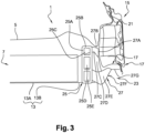
- FIG. 3 depicts a cross-section of the vehicle shown in figure 1 , after a side impact.
- the side sill profile 15 bears against the seat cross member (visible in the figure 1 ) and on the battery beam 23.
- the lateral crushing of the side profile 15 allows the dissipation of part of the energy produced at the time of impact.
- the second portion 27 of the battery spar 23 is also impacted by the shock and is deformed, which will dissipate the remaining energy produced at the time of the shock.
- the first portion 25 of said spar 23 is not altered by the impact, ensuring the protection and integrity of the battery unit 7 vis-à-vis the impact.
- the dissipation of the energy caused by the deformations of the section 15 and the spar 23 will make it possible to lower the deceleration speed at the level of the battery unit by 90g, a value obtained during the tests before the installation of the spar battery 23 according to the invention, to 70g.
- This value is satisfactory in that it corresponds to a deceleration that most traction batteries can withstand without damage.
Landscapes
- Engineering & Computer Science (AREA)
- Chemical & Material Sciences (AREA)
- Combustion & Propulsion (AREA)
- Transportation (AREA)
- Mechanical Engineering (AREA)
- Body Structure For Vehicles (AREA)
- Arrangement Or Mounting Of Propulsion Units For Vehicles (AREA)
Claims (10)
- Kraftfahrzeug (1) mit zumindest teilweise elektrischem Antrieb, bestehend aus:- einem Boden (3);- zwei seitliche Bodenkörperabschnitte (15) auf beiden Seiten des Bodens (3);- eine Antriebsbatterieeinheit (7) unter dem Boden (3) und zwischen den beiden Abschnitten (15);- mindestens einen seitlich zwischen der Antriebsbatterieeinheit (7) und mindestens einem der beiden unteren Karosserieseitenabschnitte (15) angeordneten Batterieholm (23);dadurch gekennzeichnet, dass:
der mindestens eine Batterieholm (23) weist einen Querschnitt mit einem ersten Abschnitt (25) auf der Seite der Antriebsbatterieeinheit (7) und einem zweiten Abschnitt (27) auf der Seite des entsprechenden seitlichen Bodenabschnitts (15) auf, wobei der zweite Abschnitt (27) eine Querdrucksteifigkeit aufweist, die geringer ist als eine Querdrucksteifigkeit des ersten Abschnitts (25), sodass der zweite Abschnitt (27) vorzugsweise bei einem seitlichen Aufprall auf das Fahrzeug (1) auf der Seite des Holms (23) gegenüber dem ersten Abschnitt (25) verformt wird. - Kraftfahrzeug (1) nach Anspruch 1, dadurch gekennzeichnet, dass der zweite Abschnitt (27) des Querschnitts des mindestens einen Batterieholms (23) pro Längeneinheit eine Materialoberfläche aufweist, die in Querkompression arbeitet, die weniger als 70 % einer Materialoberfläche ist, die in Querkompression des ersten Abschnitts (25) dieses Abschnitts arbeitet.
- Kraftfahrzeug (1) nach einem der Ansprüche 1 und 2, dadurch gekennzeichnet, dass der erste und der zweite Abschnitt (25, 27) des Querschnitts des mindestens einen Batterieholms (23) entlang einer vertikalen Ebene benachbart sind.
- Kraftfahrzeug (1) nach einem der Ansprüche 1 bis 3, dadurch gekennzeichnet, dass der erste und der zweite Abschnitt (25, 27) des Querschnitts des mindestens einen Batterieholms (23) einstückig sind.
- Kraftfahrzeug (1) nach einem der Ansprüche 1 bis 4, dadurch gekennzeichnet, dass der erste und der zweite Abschnitt (25, 27) des Querschnitts des mindestens einen Batterieholms (23) Wände (25A, 27A; 25B, 27B) aufweisen, die Hohlkörper (25C, 27C; 25D, 27D; 25E, 27E) bilden, wobei die Wände (27A, 27B) des zweiten Abschnitts (27) eine durchschnittliche Dicke von weniger als 70 % einer durchschnittlichen Dicke der Wände (25) aufweisen A, 25 B) des ersten Abschnitts (25).
- Kraftfahrzeug (1) nach einem der Ansprüche 1 bis 5, dadurch gekennzeichnet, dass jeder der ersten und zweiten Abschnitte (25, 27) des Querschnitts des mindestens einen Batterieholms (23) mindestens drei horizontale Wände (25B, 27B) aufweist.
- Kraftfahrzeug (1) nach einem der Ansprüche 1 bis 6, dadurch gekennzeichnet, dass jeder der beiden seitlichen Unterkörperabschnitte (15) einen Querschnitt aufweist, der einen Hohlkörper bildet, wobei sich der mindestens eine Batterieholm (23) vertikal über mindestens 50 % der Höhe des Holms (23) entlang des Hohlkörpers des entsprechenden Seitenabschnitts (15) erstreckt.
- Kraftfahrzeug (1) nach Anspruch 7, dadurch gekennzeichnet, dass der zweite Abschnitt (27) des Querschnitts des mindestens einen Batterieholms (23) an einer seitlichen Außenfläche (27F) des Abschnitts (27) eine Schulter (27G) an oder unter einer unteren Fläche (17C) des Hohlkörpers des entsprechenden seitlichen Abschnitts (15) bildet.
- Kraftfahrzeug (1) nach Anspruch 8, dadurch gekennzeichnet, dass sich der Absatz (27G) an der seitlichen Außenfläche (27F) des zweiten Abschnittes (27) des Querschnitts des mindestens einen Batterieholms (23) horizontal entlang der unteren Fläche (17C) des Hohlkörpers des entsprechenden seitlichen Abschnittes (15) erstreckt.
- Kraftfahrzeug (1) nach einem der Ansprüche 8 oder 9, dadurch gekennzeichnet, dass die Schulter (27G) an der seitlichen Außenfläche (27F) des zweiten Abschnitts (27) des Querschnitts des mindestens einen Batterieholms (23) durch einen unteren Hohlkörper (27E) des Abschnitts (27) gebildet ist, wobei der Körper (27E) eine untere Wand aufweist, die nach oben und seitlich nach außen geneigt ist.
Applications Claiming Priority (2)
| Application Number | Priority Date | Filing Date | Title |
|---|---|---|---|
| FR1854895A FR3082170B1 (fr) | 2018-06-06 | 2018-06-06 | Longeron de batterie de traction sous plancher de vehicule |
| PCT/FR2019/051044 WO2019234319A1 (fr) | 2018-06-06 | 2019-05-07 | Longeron de batterie de traction sous plancher de vehicule |
Publications (2)
| Publication Number | Publication Date |
|---|---|
| EP3802183A1 EP3802183A1 (de) | 2021-04-14 |
| EP3802183B1 true EP3802183B1 (de) | 2023-04-12 |
Family
ID=63209540
Family Applications (1)
| Application Number | Title | Priority Date | Filing Date |
|---|---|---|---|
| EP19730398.5A Active EP3802183B1 (de) | 2018-06-06 | 2019-05-07 | Antriebsbatterieschiene unterhalb des bodens eines fahrzeuges |
Country Status (3)
| Country | Link |
|---|---|
| EP (1) | EP3802183B1 (de) |
| FR (1) | FR3082170B1 (de) |
| WO (1) | WO2019234319A1 (de) |
Families Citing this family (1)
| Publication number | Priority date | Publication date | Assignee | Title |
|---|---|---|---|---|
| US11840136B2 (en) | 2021-11-19 | 2023-12-12 | Ford Global Technologies, Llc | Structural assembly and vehicle having structural assembly |
Family Cites Families (3)
| Publication number | Priority date | Publication date | Assignee | Title |
|---|---|---|---|---|
| DE102011113912B4 (de) * | 2011-09-21 | 2023-08-10 | Mercedes-Benz Group AG | Schutzeinrichtung für eine Energiespeichereinrichtung eines Personenkraftwagens |
| DE102011120960A1 (de) * | 2011-10-20 | 2013-04-25 | Volkswagen Ag | Batterieanordnung in einem Fahrzeug |
| WO2013186877A1 (ja) * | 2012-06-13 | 2013-12-19 | 本田技研工業株式会社 | 車両用通信装置のアンテナ配置構造 |
-
2018
- 2018-06-06 FR FR1854895A patent/FR3082170B1/fr not_active Expired - Fee Related
-
2019
- 2019-05-07 EP EP19730398.5A patent/EP3802183B1/de active Active
- 2019-05-07 WO PCT/FR2019/051044 patent/WO2019234319A1/fr not_active Ceased
Also Published As
| Publication number | Publication date |
|---|---|
| WO2019234319A1 (fr) | 2019-12-12 |
| FR3082170A1 (fr) | 2019-12-13 |
| EP3802183A1 (de) | 2021-04-14 |
| FR3082170B1 (fr) | 2020-09-04 |
Similar Documents
| Publication | Publication Date | Title |
|---|---|---|
| EP1369309A1 (de) | Stossfängerträger und Kraftfahrzeug mit einem solchen Träger | |
| EP3802183B1 (de) | Antriebsbatterieschiene unterhalb des bodens eines fahrzeuges | |
| WO2024009016A1 (fr) | Dispositif de protection contre les chocs latéraux, pour une structure d'un véhicule terrestre | |
| EP4267419B1 (de) | Unterbodenstruktur für ein kraftfahrzeug | |
| EP4511277A1 (de) | Kraftfahrzeug mit einem seitenglied mit einem verstärkungsteil | |
| WO2024018122A1 (fr) | Soubassement de caisse pour véhicule hybride ou électrique doté de longerons latéraux renforcés | |
| EP4072925B1 (de) | Elektrisch angetriebenes kraftfahrzeug mit verstärkter wippe | |
| WO2021229159A1 (fr) | Renfort latéral de plancher de véhicule automobile équipé de batteries de traction | |
| EP1473197A1 (de) | Kraftfahrzeug-Stossfänger mit energieabsorbierenden Elementen, und mit einem solchen Stossfänger ausgerüstetes Kraftfahrzeug | |
| WO2022162288A1 (fr) | Structure de véhicule automobile | |
| FR3119596A1 (fr) | Plancher de véhicule automobile avec aménagement côté tunnel central pour batteries de traction | |
| FR3120046A1 (fr) | Ensemble absorbeur de chocs pour véhicule automobile | |
| WO2024079400A1 (fr) | Ensemble structurel à déformation programmée pour une structure de véhicule automobile | |
| FR3148773A1 (fr) | Soubassement pour véhicule automobile électrique ou hybride | |
| FR3128687A1 (fr) | Véhicule automobile avec traverse d’assise sur batteries de traction | |
| FR3140340A1 (fr) | Longeron à cinématique de déformation programmée, pour un véhicule | |
| FR3148170A1 (fr) | Caisson plat de batterie de traction de vehicule equipe d’un couvercle avec nervures de renfort inclinees | |
| FR3134783A1 (fr) | Berceau arrière à résistance renforcée, pour un véhicule terrestre | |
| FR2979598A1 (fr) | Poutre de pare-chocs de vehicule automobile | |
| FR3012103A3 (fr) | Ensemble de voie avant de vehicule automobile | |
| FR3165586A1 (fr) | Structure à répartition d’effort en cas de choc par l’arrière, pour un triporteur à machine motrice électrique | |
| FR3122377A1 (fr) | Traverse de pare-chocs | |
| FR2966103A1 (fr) | Partie avant de la caisse d'un vehicule automobile comportant deux bretelles reliant la traverse superieure a la traverse inferieure et vehicule ainsi equipe | |
| EP3661814A1 (de) | Stossdämpferanordnung für kraftfahrzeug | |
| FR3061116A1 (fr) | Paroi de chassis pour chassis d'un vehicule de transport et chassis associe |
Legal Events
| Date | Code | Title | Description |
|---|---|---|---|
| STAA | Information on the status of an ep patent application or granted ep patent |
Free format text: STATUS: UNKNOWN |
|
| STAA | Information on the status of an ep patent application or granted ep patent |
Free format text: STATUS: THE INTERNATIONAL PUBLICATION HAS BEEN MADE |
|
| PUAI | Public reference made under article 153(3) epc to a published international application that has entered the european phase |
Free format text: ORIGINAL CODE: 0009012 |
|
| STAA | Information on the status of an ep patent application or granted ep patent |
Free format text: STATUS: REQUEST FOR EXAMINATION WAS MADE |
|
| 17P | Request for examination filed |
Effective date: 20201217 |
|
| AK | Designated contracting states |
Kind code of ref document: A1 Designated state(s): AL AT BE BG CH CY CZ DE DK EE ES FI FR GB GR HR HU IE IS IT LI LT LU LV MC MK MT NL NO PL PT RO RS SE SI SK SM TR |
|
| AX | Request for extension of the european patent |
Extension state: BA ME |
|
| DAV | Request for validation of the european patent (deleted) | ||
| DAX | Request for extension of the european patent (deleted) | ||
| GRAP | Despatch of communication of intention to grant a patent |
Free format text: ORIGINAL CODE: EPIDOSNIGR1 |
|
| STAA | Information on the status of an ep patent application or granted ep patent |
Free format text: STATUS: GRANT OF PATENT IS INTENDED |
|
| INTG | Intention to grant announced |
Effective date: 20221223 |
|
| GRAS | Grant fee paid |
Free format text: ORIGINAL CODE: EPIDOSNIGR3 |
|
| GRAA | (expected) grant |
Free format text: ORIGINAL CODE: 0009210 |
|
| STAA | Information on the status of an ep patent application or granted ep patent |
Free format text: STATUS: THE PATENT HAS BEEN GRANTED |
|
| AK | Designated contracting states |
Kind code of ref document: B1 Designated state(s): AL AT BE BG CH CY CZ DE DK EE ES FI FR GB GR HR HU IE IS IT LI LT LU LV MC MK MT NL NO PL PT RO RS SE SI SK SM TR |
|
| REG | Reference to a national code |
Ref country code: DE Ref legal event code: R084 Ref document number: 602019027476 Country of ref document: DE Ref country code: GB Ref legal event code: FG4D Free format text: NOT ENGLISH |
|
| REG | Reference to a national code |
Ref country code: CH Ref legal event code: EP |
|
| REG | Reference to a national code |
Ref country code: DE Ref legal event code: R096 Ref document number: 602019027476 Country of ref document: DE |
|
| REG | Reference to a national code |
Ref country code: IE Ref legal event code: FG4D Free format text: LANGUAGE OF EP DOCUMENT: FRENCH |
|
| REG | Reference to a national code |
Ref country code: AT Ref legal event code: REF Ref document number: 1559576 Country of ref document: AT Kind code of ref document: T Effective date: 20230515 |
|
| REG | Reference to a national code |
Ref country code: GB Ref legal event code: 746 Effective date: 20230509 |
|
| REG | Reference to a national code |
Ref country code: LT Ref legal event code: MG9D |
|
| REG | Reference to a national code |
Ref country code: NL Ref legal event code: MP Effective date: 20230412 |
|
| REG | Reference to a national code |
Ref country code: AT Ref legal event code: MK05 Ref document number: 1559576 Country of ref document: AT Kind code of ref document: T Effective date: 20230412 |
|
| PG25 | Lapsed in a contracting state [announced via postgrant information from national office to epo] |
Ref country code: NL Free format text: LAPSE BECAUSE OF FAILURE TO SUBMIT A TRANSLATION OF THE DESCRIPTION OR TO PAY THE FEE WITHIN THE PRESCRIBED TIME-LIMIT Effective date: 20230412 |
|
| PG25 | Lapsed in a contracting state [announced via postgrant information from national office to epo] |
Ref country code: SE Free format text: LAPSE BECAUSE OF FAILURE TO SUBMIT A TRANSLATION OF THE DESCRIPTION OR TO PAY THE FEE WITHIN THE PRESCRIBED TIME-LIMIT Effective date: 20230412 Ref country code: PT Free format text: LAPSE BECAUSE OF FAILURE TO SUBMIT A TRANSLATION OF THE DESCRIPTION OR TO PAY THE FEE WITHIN THE PRESCRIBED TIME-LIMIT Effective date: 20230814 Ref country code: NO Free format text: LAPSE BECAUSE OF FAILURE TO SUBMIT A TRANSLATION OF THE DESCRIPTION OR TO PAY THE FEE WITHIN THE PRESCRIBED TIME-LIMIT Effective date: 20230712 Ref country code: ES Free format text: LAPSE BECAUSE OF FAILURE TO SUBMIT A TRANSLATION OF THE DESCRIPTION OR TO PAY THE FEE WITHIN THE PRESCRIBED TIME-LIMIT Effective date: 20230412 Ref country code: AT Free format text: LAPSE BECAUSE OF FAILURE TO SUBMIT A TRANSLATION OF THE DESCRIPTION OR TO PAY THE FEE WITHIN THE PRESCRIBED TIME-LIMIT Effective date: 20230412 |
|
| PG25 | Lapsed in a contracting state [announced via postgrant information from national office to epo] |
Ref country code: RS Free format text: LAPSE BECAUSE OF FAILURE TO SUBMIT A TRANSLATION OF THE DESCRIPTION OR TO PAY THE FEE WITHIN THE PRESCRIBED TIME-LIMIT Effective date: 20230412 Ref country code: PL Free format text: LAPSE BECAUSE OF FAILURE TO SUBMIT A TRANSLATION OF THE DESCRIPTION OR TO PAY THE FEE WITHIN THE PRESCRIBED TIME-LIMIT Effective date: 20230412 Ref country code: LV Free format text: LAPSE BECAUSE OF FAILURE TO SUBMIT A TRANSLATION OF THE DESCRIPTION OR TO PAY THE FEE WITHIN THE PRESCRIBED TIME-LIMIT Effective date: 20230412 Ref country code: LT Free format text: LAPSE BECAUSE OF FAILURE TO SUBMIT A TRANSLATION OF THE DESCRIPTION OR TO PAY THE FEE WITHIN THE PRESCRIBED TIME-LIMIT Effective date: 20230412 Ref country code: IS Free format text: LAPSE BECAUSE OF FAILURE TO SUBMIT A TRANSLATION OF THE DESCRIPTION OR TO PAY THE FEE WITHIN THE PRESCRIBED TIME-LIMIT Effective date: 20230812 Ref country code: HR Free format text: LAPSE BECAUSE OF FAILURE TO SUBMIT A TRANSLATION OF THE DESCRIPTION OR TO PAY THE FEE WITHIN THE PRESCRIBED TIME-LIMIT Effective date: 20230412 Ref country code: GR Free format text: LAPSE BECAUSE OF FAILURE TO SUBMIT A TRANSLATION OF THE DESCRIPTION OR TO PAY THE FEE WITHIN THE PRESCRIBED TIME-LIMIT Effective date: 20230713 Ref country code: AL Free format text: LAPSE BECAUSE OF FAILURE TO SUBMIT A TRANSLATION OF THE DESCRIPTION OR TO PAY THE FEE WITHIN THE PRESCRIBED TIME-LIMIT Effective date: 20230412 |
|
| RAP4 | Party data changed (patent owner data changed or rights of a patent transferred) |
Owner name: STELLANTIS AUTO SAS |
|
| PG25 | Lapsed in a contracting state [announced via postgrant information from national office to epo] |
Ref country code: FI Free format text: LAPSE BECAUSE OF FAILURE TO SUBMIT A TRANSLATION OF THE DESCRIPTION OR TO PAY THE FEE WITHIN THE PRESCRIBED TIME-LIMIT Effective date: 20230412 |
|
| REG | Reference to a national code |
Ref country code: CH Ref legal event code: PL |
|
| REG | Reference to a national code |
Ref country code: DE Ref legal event code: R097 Ref document number: 602019027476 Country of ref document: DE |
|
| PG25 | Lapsed in a contracting state [announced via postgrant information from national office to epo] |
Ref country code: SK Free format text: LAPSE BECAUSE OF FAILURE TO SUBMIT A TRANSLATION OF THE DESCRIPTION OR TO PAY THE FEE WITHIN THE PRESCRIBED TIME-LIMIT Effective date: 20230412 |
|
| PG25 | Lapsed in a contracting state [announced via postgrant information from national office to epo] |
Ref country code: MC Free format text: LAPSE BECAUSE OF FAILURE TO SUBMIT A TRANSLATION OF THE DESCRIPTION OR TO PAY THE FEE WITHIN THE PRESCRIBED TIME-LIMIT Effective date: 20230412 |
|
| REG | Reference to a national code |
Ref country code: BE Ref legal event code: MM Effective date: 20230531 |
|
| PG25 | Lapsed in a contracting state [announced via postgrant information from national office to epo] |
Ref country code: SM Free format text: LAPSE BECAUSE OF FAILURE TO SUBMIT A TRANSLATION OF THE DESCRIPTION OR TO PAY THE FEE WITHIN THE PRESCRIBED TIME-LIMIT Effective date: 20230412 Ref country code: SK Free format text: LAPSE BECAUSE OF FAILURE TO SUBMIT A TRANSLATION OF THE DESCRIPTION OR TO PAY THE FEE WITHIN THE PRESCRIBED TIME-LIMIT Effective date: 20230412 Ref country code: RO Free format text: LAPSE BECAUSE OF FAILURE TO SUBMIT A TRANSLATION OF THE DESCRIPTION OR TO PAY THE FEE WITHIN THE PRESCRIBED TIME-LIMIT Effective date: 20230412 Ref country code: MC Free format text: LAPSE BECAUSE OF FAILURE TO SUBMIT A TRANSLATION OF THE DESCRIPTION OR TO PAY THE FEE WITHIN THE PRESCRIBED TIME-LIMIT Effective date: 20230412 Ref country code: LU Free format text: LAPSE BECAUSE OF NON-PAYMENT OF DUE FEES Effective date: 20230507 Ref country code: LI Free format text: LAPSE BECAUSE OF NON-PAYMENT OF DUE FEES Effective date: 20230531 Ref country code: EE Free format text: LAPSE BECAUSE OF FAILURE TO SUBMIT A TRANSLATION OF THE DESCRIPTION OR TO PAY THE FEE WITHIN THE PRESCRIBED TIME-LIMIT Effective date: 20230412 Ref country code: DK Free format text: LAPSE BECAUSE OF FAILURE TO SUBMIT A TRANSLATION OF THE DESCRIPTION OR TO PAY THE FEE WITHIN THE PRESCRIBED TIME-LIMIT Effective date: 20230412 Ref country code: CZ Free format text: LAPSE BECAUSE OF FAILURE TO SUBMIT A TRANSLATION OF THE DESCRIPTION OR TO PAY THE FEE WITHIN THE PRESCRIBED TIME-LIMIT Effective date: 20230412 Ref country code: CH Free format text: LAPSE BECAUSE OF NON-PAYMENT OF DUE FEES Effective date: 20230531 |
|
| PLBE | No opposition filed within time limit |
Free format text: ORIGINAL CODE: 0009261 |
|
| STAA | Information on the status of an ep patent application or granted ep patent |
Free format text: STATUS: NO OPPOSITION FILED WITHIN TIME LIMIT |
|
| REG | Reference to a national code |
Ref country code: IE Ref legal event code: MM4A |
|
| 26N | No opposition filed |
Effective date: 20240115 |
|
| REG | Reference to a national code |
Ref country code: DE Ref legal event code: R081 Ref document number: 602019027476 Country of ref document: DE Owner name: STELLANTIS AUTO SAS, FR Free format text: FORMER OWNER: PSA AUTOMOBILES SA, POISSY, FR |
|
| PG25 | Lapsed in a contracting state [announced via postgrant information from national office to epo] |
Ref country code: IE Free format text: LAPSE BECAUSE OF NON-PAYMENT OF DUE FEES Effective date: 20230507 |
|
| PG25 | Lapsed in a contracting state [announced via postgrant information from national office to epo] |
Ref country code: IE Free format text: LAPSE BECAUSE OF NON-PAYMENT OF DUE FEES Effective date: 20230507 |
|
| PG25 | Lapsed in a contracting state [announced via postgrant information from national office to epo] |
Ref country code: SI Free format text: LAPSE BECAUSE OF FAILURE TO SUBMIT A TRANSLATION OF THE DESCRIPTION OR TO PAY THE FEE WITHIN THE PRESCRIBED TIME-LIMIT Effective date: 20230412 |
|
| PG25 | Lapsed in a contracting state [announced via postgrant information from national office to epo] |
Ref country code: SI Free format text: LAPSE BECAUSE OF FAILURE TO SUBMIT A TRANSLATION OF THE DESCRIPTION OR TO PAY THE FEE WITHIN THE PRESCRIBED TIME-LIMIT Effective date: 20230412 Ref country code: BE Free format text: LAPSE BECAUSE OF NON-PAYMENT OF DUE FEES Effective date: 20230531 |
|
| PG25 | Lapsed in a contracting state [announced via postgrant information from national office to epo] |
Ref country code: BG Free format text: LAPSE BECAUSE OF FAILURE TO SUBMIT A TRANSLATION OF THE DESCRIPTION OR TO PAY THE FEE WITHIN THE PRESCRIBED TIME-LIMIT Effective date: 20230412 |
|
| PG25 | Lapsed in a contracting state [announced via postgrant information from national office to epo] |
Ref country code: BG Free format text: LAPSE BECAUSE OF FAILURE TO SUBMIT A TRANSLATION OF THE DESCRIPTION OR TO PAY THE FEE WITHIN THE PRESCRIBED TIME-LIMIT Effective date: 20230412 |
|
| PGFP | Annual fee paid to national office [announced via postgrant information from national office to epo] |
Ref country code: DE Payment date: 20250423 Year of fee payment: 7 |
|
| PGFP | Annual fee paid to national office [announced via postgrant information from national office to epo] |
Ref country code: GB Payment date: 20250423 Year of fee payment: 7 |
|
| PGFP | Annual fee paid to national office [announced via postgrant information from national office to epo] |
Ref country code: IT Payment date: 20250423 Year of fee payment: 7 |
|
| PGFP | Annual fee paid to national office [announced via postgrant information from national office to epo] |
Ref country code: FR Payment date: 20250424 Year of fee payment: 7 |
|
| PG25 | Lapsed in a contracting state [announced via postgrant information from national office to epo] |
Ref country code: CY Free format text: LAPSE BECAUSE OF FAILURE TO SUBMIT A TRANSLATION OF THE DESCRIPTION OR TO PAY THE FEE WITHIN THE PRESCRIBED TIME-LIMIT; INVALID AB INITIO Effective date: 20190507 |
|
| PG25 | Lapsed in a contracting state [announced via postgrant information from national office to epo] |
Ref country code: HU Free format text: LAPSE BECAUSE OF FAILURE TO SUBMIT A TRANSLATION OF THE DESCRIPTION OR TO PAY THE FEE WITHIN THE PRESCRIBED TIME-LIMIT; INVALID AB INITIO Effective date: 20190507 |
|
| PG25 | Lapsed in a contracting state [announced via postgrant information from national office to epo] |
Ref country code: TR Free format text: LAPSE BECAUSE OF FAILURE TO SUBMIT A TRANSLATION OF THE DESCRIPTION OR TO PAY THE FEE WITHIN THE PRESCRIBED TIME-LIMIT Effective date: 20230412 |