EP3802247B1 - Système de freinage muni de deux sources de pression et procédé permettant de faire fonctionner un système de freinage muni de deux sources de pression - Google Patents
Système de freinage muni de deux sources de pression et procédé permettant de faire fonctionner un système de freinage muni de deux sources de pression Download PDFInfo
- Publication number
- EP3802247B1 EP3802247B1 EP19725101.0A EP19725101A EP3802247B1 EP 3802247 B1 EP3802247 B1 EP 3802247B1 EP 19725101 A EP19725101 A EP 19725101A EP 3802247 B1 EP3802247 B1 EP 3802247B1
- Authority
- EP
- European Patent Office
- Prior art keywords
- brake
- pressure
- control
- circuit
- brake circuit
- Prior art date
- Legal status (The legal status is an assumption and is not a legal conclusion. Google has not performed a legal analysis and makes no representation as to the accuracy of the status listed.)
- Active
Links
Images


Classifications
-
- B—PERFORMING OPERATIONS; TRANSPORTING
- B60—VEHICLES IN GENERAL
- B60T—VEHICLE BRAKE CONTROL SYSTEMS OR PARTS THEREOF; BRAKE CONTROL SYSTEMS OR PARTS THEREOF, IN GENERAL; ARRANGEMENT OF BRAKING ELEMENTS ON VEHICLES IN GENERAL; PORTABLE DEVICES FOR PREVENTING UNWANTED MOVEMENT OF VEHICLES; VEHICLE MODIFICATIONS TO FACILITATE COOLING OF BRAKES
- B60T13/00—Transmitting braking action from initiating means to ultimate brake actuator with power assistance or drive; Brake systems incorporating such transmitting means, e.g. air-pressure brake systems
- B60T13/10—Transmitting braking action from initiating means to ultimate brake actuator with power assistance or drive; Brake systems incorporating such transmitting means, e.g. air-pressure brake systems with fluid assistance, drive, or release
- B60T13/58—Combined or convertible systems
-
- B—PERFORMING OPERATIONS; TRANSPORTING
- B60—VEHICLES IN GENERAL
- B60T—VEHICLE BRAKE CONTROL SYSTEMS OR PARTS THEREOF; BRAKE CONTROL SYSTEMS OR PARTS THEREOF, IN GENERAL; ARRANGEMENT OF BRAKING ELEMENTS ON VEHICLES IN GENERAL; PORTABLE DEVICES FOR PREVENTING UNWANTED MOVEMENT OF VEHICLES; VEHICLE MODIFICATIONS TO FACILITATE COOLING OF BRAKES
- B60T13/00—Transmitting braking action from initiating means to ultimate brake actuator with power assistance or drive; Brake systems incorporating such transmitting means, e.g. air-pressure brake systems
- B60T13/74—Transmitting braking action from initiating means to ultimate brake actuator with power assistance or drive; Brake systems incorporating such transmitting means, e.g. air-pressure brake systems with electrical assistance or drive
- B60T13/745—Transmitting braking action from initiating means to ultimate brake actuator with power assistance or drive; Brake systems incorporating such transmitting means, e.g. air-pressure brake systems with electrical assistance or drive acting on a hydraulic system, e.g. a master cylinder
-
- B—PERFORMING OPERATIONS; TRANSPORTING
- B60—VEHICLES IN GENERAL
- B60T—VEHICLE BRAKE CONTROL SYSTEMS OR PARTS THEREOF; BRAKE CONTROL SYSTEMS OR PARTS THEREOF, IN GENERAL; ARRANGEMENT OF BRAKING ELEMENTS ON VEHICLES IN GENERAL; PORTABLE DEVICES FOR PREVENTING UNWANTED MOVEMENT OF VEHICLES; VEHICLE MODIFICATIONS TO FACILITATE COOLING OF BRAKES
- B60T15/00—Construction arrangement, or operation of valves incorporated in power brake systems and not covered by groups B60T11/00 or B60T13/00
- B60T15/02—Application and release valves
- B60T15/025—Electrically controlled valves
- B60T15/028—Electrically controlled valves in hydraulic systems
-
- B—PERFORMING OPERATIONS; TRANSPORTING
- B60—VEHICLES IN GENERAL
- B60T—VEHICLE BRAKE CONTROL SYSTEMS OR PARTS THEREOF; BRAKE CONTROL SYSTEMS OR PARTS THEREOF, IN GENERAL; ARRANGEMENT OF BRAKING ELEMENTS ON VEHICLES IN GENERAL; PORTABLE DEVICES FOR PREVENTING UNWANTED MOVEMENT OF VEHICLES; VEHICLE MODIFICATIONS TO FACILITATE COOLING OF BRAKES
- B60T8/00—Arrangements for adjusting wheel-braking force to meet varying vehicular or ground-surface conditions, e.g. limiting or varying distribution of braking force
- B60T8/17—Using electrical or electronic regulation means to control braking
-
- B—PERFORMING OPERATIONS; TRANSPORTING
- B60—VEHICLES IN GENERAL
- B60T—VEHICLE BRAKE CONTROL SYSTEMS OR PARTS THEREOF; BRAKE CONTROL SYSTEMS OR PARTS THEREOF, IN GENERAL; ARRANGEMENT OF BRAKING ELEMENTS ON VEHICLES IN GENERAL; PORTABLE DEVICES FOR PREVENTING UNWANTED MOVEMENT OF VEHICLES; VEHICLE MODIFICATIONS TO FACILITATE COOLING OF BRAKES
- B60T8/00—Arrangements for adjusting wheel-braking force to meet varying vehicular or ground-surface conditions, e.g. limiting or varying distribution of braking force
- B60T8/32—Arrangements for adjusting wheel-braking force to meet varying vehicular or ground-surface conditions, e.g. limiting or varying distribution of braking force responsive to a speed condition, e.g. acceleration or deceleration
- B60T8/321—Arrangements for adjusting wheel-braking force to meet varying vehicular or ground-surface conditions, e.g. limiting or varying distribution of braking force responsive to a speed condition, e.g. acceleration or deceleration deceleration
- B60T8/3255—Systems in which the braking action is dependent on brake pedal data
- B60T8/326—Hydraulic systems
-
- B—PERFORMING OPERATIONS; TRANSPORTING
- B60—VEHICLES IN GENERAL
- B60T—VEHICLE BRAKE CONTROL SYSTEMS OR PARTS THEREOF; BRAKE CONTROL SYSTEMS OR PARTS THEREOF, IN GENERAL; ARRANGEMENT OF BRAKING ELEMENTS ON VEHICLES IN GENERAL; PORTABLE DEVICES FOR PREVENTING UNWANTED MOVEMENT OF VEHICLES; VEHICLE MODIFICATIONS TO FACILITATE COOLING OF BRAKES
- B60T8/00—Arrangements for adjusting wheel-braking force to meet varying vehicular or ground-surface conditions, e.g. limiting or varying distribution of braking force
- B60T8/32—Arrangements for adjusting wheel-braking force to meet varying vehicular or ground-surface conditions, e.g. limiting or varying distribution of braking force responsive to a speed condition, e.g. acceleration or deceleration
- B60T8/88—Arrangements for adjusting wheel-braking force to meet varying vehicular or ground-surface conditions, e.g. limiting or varying distribution of braking force responsive to a speed condition, e.g. acceleration or deceleration with failure responsive means, i.e. means for detecting and indicating faulty operation of the speed responsive control means
- B60T8/885—Arrangements for adjusting wheel-braking force to meet varying vehicular or ground-surface conditions, e.g. limiting or varying distribution of braking force responsive to a speed condition, e.g. acceleration or deceleration with failure responsive means, i.e. means for detecting and indicating faulty operation of the speed responsive control means using electrical circuitry
-
- B—PERFORMING OPERATIONS; TRANSPORTING
- B60—VEHICLES IN GENERAL
- B60T—VEHICLE BRAKE CONTROL SYSTEMS OR PARTS THEREOF; BRAKE CONTROL SYSTEMS OR PARTS THEREOF, IN GENERAL; ARRANGEMENT OF BRAKING ELEMENTS ON VEHICLES IN GENERAL; PORTABLE DEVICES FOR PREVENTING UNWANTED MOVEMENT OF VEHICLES; VEHICLE MODIFICATIONS TO FACILITATE COOLING OF BRAKES
- B60T13/00—Transmitting braking action from initiating means to ultimate brake actuator with power assistance or drive; Brake systems incorporating such transmitting means, e.g. air-pressure brake systems
- B60T13/10—Transmitting braking action from initiating means to ultimate brake actuator with power assistance or drive; Brake systems incorporating such transmitting means, e.g. air-pressure brake systems with fluid assistance, drive, or release
- B60T13/12—Transmitting braking action from initiating means to ultimate brake actuator with power assistance or drive; Brake systems incorporating such transmitting means, e.g. air-pressure brake systems with fluid assistance, drive, or release the fluid being liquid
- B60T13/16—Transmitting braking action from initiating means to ultimate brake actuator with power assistance or drive; Brake systems incorporating such transmitting means, e.g. air-pressure brake systems with fluid assistance, drive, or release the fluid being liquid using pumps directly, i.e. without interposition of accumulators or reservoirs
-
- B—PERFORMING OPERATIONS; TRANSPORTING
- B60—VEHICLES IN GENERAL
- B60T—VEHICLE BRAKE CONTROL SYSTEMS OR PARTS THEREOF; BRAKE CONTROL SYSTEMS OR PARTS THEREOF, IN GENERAL; ARRANGEMENT OF BRAKING ELEMENTS ON VEHICLES IN GENERAL; PORTABLE DEVICES FOR PREVENTING UNWANTED MOVEMENT OF VEHICLES; VEHICLE MODIFICATIONS TO FACILITATE COOLING OF BRAKES
- B60T13/00—Transmitting braking action from initiating means to ultimate brake actuator with power assistance or drive; Brake systems incorporating such transmitting means, e.g. air-pressure brake systems
- B60T13/10—Transmitting braking action from initiating means to ultimate brake actuator with power assistance or drive; Brake systems incorporating such transmitting means, e.g. air-pressure brake systems with fluid assistance, drive, or release
- B60T13/12—Transmitting braking action from initiating means to ultimate brake actuator with power assistance or drive; Brake systems incorporating such transmitting means, e.g. air-pressure brake systems with fluid assistance, drive, or release the fluid being liquid
- B60T13/16—Transmitting braking action from initiating means to ultimate brake actuator with power assistance or drive; Brake systems incorporating such transmitting means, e.g. air-pressure brake systems with fluid assistance, drive, or release the fluid being liquid using pumps directly, i.e. without interposition of accumulators or reservoirs
- B60T13/161—Systems with master cylinder
-
- B—PERFORMING OPERATIONS; TRANSPORTING
- B60—VEHICLES IN GENERAL
- B60T—VEHICLE BRAKE CONTROL SYSTEMS OR PARTS THEREOF; BRAKE CONTROL SYSTEMS OR PARTS THEREOF, IN GENERAL; ARRANGEMENT OF BRAKING ELEMENTS ON VEHICLES IN GENERAL; PORTABLE DEVICES FOR PREVENTING UNWANTED MOVEMENT OF VEHICLES; VEHICLE MODIFICATIONS TO FACILITATE COOLING OF BRAKES
- B60T2220/00—Monitoring, detecting driver behaviour; Signalling thereof; Counteracting thereof
- B60T2220/04—Pedal travel sensor, stroke sensor; Sensing brake request
-
- B—PERFORMING OPERATIONS; TRANSPORTING
- B60—VEHICLES IN GENERAL
- B60T—VEHICLE BRAKE CONTROL SYSTEMS OR PARTS THEREOF; BRAKE CONTROL SYSTEMS OR PARTS THEREOF, IN GENERAL; ARRANGEMENT OF BRAKING ELEMENTS ON VEHICLES IN GENERAL; PORTABLE DEVICES FOR PREVENTING UNWANTED MOVEMENT OF VEHICLES; VEHICLE MODIFICATIONS TO FACILITATE COOLING OF BRAKES
- B60T2270/00—Further aspects of brake control systems not otherwise provided for
- B60T2270/40—Failsafe aspects of brake control systems
- B60T2270/402—Back-up
-
- B—PERFORMING OPERATIONS; TRANSPORTING
- B60—VEHICLES IN GENERAL
- B60T—VEHICLE BRAKE CONTROL SYSTEMS OR PARTS THEREOF; BRAKE CONTROL SYSTEMS OR PARTS THEREOF, IN GENERAL; ARRANGEMENT OF BRAKING ELEMENTS ON VEHICLES IN GENERAL; PORTABLE DEVICES FOR PREVENTING UNWANTED MOVEMENT OF VEHICLES; VEHICLE MODIFICATIONS TO FACILITATE COOLING OF BRAKES
- B60T2270/00—Further aspects of brake control systems not otherwise provided for
- B60T2270/40—Failsafe aspects of brake control systems
- B60T2270/403—Brake circuit failure
-
- B—PERFORMING OPERATIONS; TRANSPORTING
- B60—VEHICLES IN GENERAL
- B60T—VEHICLE BRAKE CONTROL SYSTEMS OR PARTS THEREOF; BRAKE CONTROL SYSTEMS OR PARTS THEREOF, IN GENERAL; ARRANGEMENT OF BRAKING ELEMENTS ON VEHICLES IN GENERAL; PORTABLE DEVICES FOR PREVENTING UNWANTED MOVEMENT OF VEHICLES; VEHICLE MODIFICATIONS TO FACILITATE COOLING OF BRAKES
- B60T2270/00—Further aspects of brake control systems not otherwise provided for
- B60T2270/40—Failsafe aspects of brake control systems
- B60T2270/404—Brake-by-wire or X-by-wire failsafe
-
- B—PERFORMING OPERATIONS; TRANSPORTING
- B60—VEHICLES IN GENERAL
- B60T—VEHICLE BRAKE CONTROL SYSTEMS OR PARTS THEREOF; BRAKE CONTROL SYSTEMS OR PARTS THEREOF, IN GENERAL; ARRANGEMENT OF BRAKING ELEMENTS ON VEHICLES IN GENERAL; PORTABLE DEVICES FOR PREVENTING UNWANTED MOVEMENT OF VEHICLES; VEHICLE MODIFICATIONS TO FACILITATE COOLING OF BRAKES
- B60T2270/00—Further aspects of brake control systems not otherwise provided for
- B60T2270/40—Failsafe aspects of brake control systems
- B60T2270/413—Plausibility monitoring, cross check, redundancy
-
- B—PERFORMING OPERATIONS; TRANSPORTING
- B60—VEHICLES IN GENERAL
- B60T—VEHICLE BRAKE CONTROL SYSTEMS OR PARTS THEREOF; BRAKE CONTROL SYSTEMS OR PARTS THEREOF, IN GENERAL; ARRANGEMENT OF BRAKING ELEMENTS ON VEHICLES IN GENERAL; PORTABLE DEVICES FOR PREVENTING UNWANTED MOVEMENT OF VEHICLES; VEHICLE MODIFICATIONS TO FACILITATE COOLING OF BRAKES
- B60T2270/00—Further aspects of brake control systems not otherwise provided for
- B60T2270/82—Brake-by-Wire, EHB
-
- B—PERFORMING OPERATIONS; TRANSPORTING
- B60—VEHICLES IN GENERAL
- B60T—VEHICLE BRAKE CONTROL SYSTEMS OR PARTS THEREOF; BRAKE CONTROL SYSTEMS OR PARTS THEREOF, IN GENERAL; ARRANGEMENT OF BRAKING ELEMENTS ON VEHICLES IN GENERAL; PORTABLE DEVICES FOR PREVENTING UNWANTED MOVEMENT OF VEHICLES; VEHICLE MODIFICATIONS TO FACILITATE COOLING OF BRAKES
- B60T7/00—Brake-action initiating means
- B60T7/02—Brake-action initiating means for personal initiation
- B60T7/04—Brake-action initiating means for personal initiation foot actuated
- B60T7/042—Brake-action initiating means for personal initiation foot actuated by electrical means, e.g. using travel or force sensors
-
- B—PERFORMING OPERATIONS; TRANSPORTING
- B60—VEHICLES IN GENERAL
- B60T—VEHICLE BRAKE CONTROL SYSTEMS OR PARTS THEREOF; BRAKE CONTROL SYSTEMS OR PARTS THEREOF, IN GENERAL; ARRANGEMENT OF BRAKING ELEMENTS ON VEHICLES IN GENERAL; PORTABLE DEVICES FOR PREVENTING UNWANTED MOVEMENT OF VEHICLES; VEHICLE MODIFICATIONS TO FACILITATE COOLING OF BRAKES
- B60T8/00—Arrangements for adjusting wheel-braking force to meet varying vehicular or ground-surface conditions, e.g. limiting or varying distribution of braking force
- B60T8/32—Arrangements for adjusting wheel-braking force to meet varying vehicular or ground-surface conditions, e.g. limiting or varying distribution of braking force responsive to a speed condition, e.g. acceleration or deceleration
- B60T8/34—Arrangements for adjusting wheel-braking force to meet varying vehicular or ground-surface conditions, e.g. limiting or varying distribution of braking force responsive to a speed condition, e.g. acceleration or deceleration having a fluid pressure regulator responsive to a speed condition
- B60T8/40—Arrangements for adjusting wheel-braking force to meet varying vehicular or ground-surface conditions, e.g. limiting or varying distribution of braking force responsive to a speed condition, e.g. acceleration or deceleration having a fluid pressure regulator responsive to a speed condition comprising an additional fluid circuit including fluid pressurising means for modifying the pressure of the braking fluid, e.g. including wheel driven pumps for detecting a speed condition, or pumps which are controlled by means independent of the braking system
- B60T8/4072—Systems in which a driver input signal is used as a control signal for the additional fluid circuit which is normally used for braking
- B60T8/4081—Systems with stroke simulating devices for driver input
-
- B—PERFORMING OPERATIONS; TRANSPORTING
- B60—VEHICLES IN GENERAL
- B60Y—INDEXING SCHEME RELATING TO ASPECTS CROSS-CUTTING VEHICLE TECHNOLOGY
- B60Y2400/00—Special features of vehicle units
- B60Y2400/81—Braking systems
Definitions
- the invention relates to a braking system according to the preamble of claim 1. It further relates to a method for operating such a braking system.
- a pedal decoupling unit and a simulator are usually activated, with the driver's braking request being recorded by a sensor system.
- the pedal simulator is used to give the driver as familiar a brake pedal feeling as possible.
- the recorded braking request leads to the determination of a target braking torque, from which the target braking pressure for the brakes is then determined.
- the braking pressure is then actively built up by a pressure supply device in the brakes.
- the actual braking is therefore carried out by actively building up pressure in the brake circuits with the help of a pressure supply device that is controlled by a control and regulation unit.
- a pressure supply device that is controlled by a control and regulation unit.
- actuators are designed as linear actuators in which a piston is axially displaced into a hydraulic pressure chamber in order to build up pressure.
- the piston is built in series with a rotation-translation gear.
- the motor shaft of an electric motor is converted into an axial displacement of the piston by the rotation-translation gear.
- a "Brake-by-Wire" braking system for motor vehicles which has a brake pedal-operated Tandem master brake cylinder, the pressure chambers of which are each separably connected to a brake circuit with two wheel brakes via an electrically actuated isolating valve, a simulation device which is hydraulically connected to the master brake cylinder and can be switched on and off, and an electrically controllable pressure supply device which is formed by a cylinder-piston arrangement with a hydraulic pressure chamber, the piston of which can be displaced by an electromechanical actuator, wherein the pressure supply device is connected to the inlet valves of the wheel brakes via two electrically actuated connection valves.
- the required system pressure is set using a suitable pressure regulator or a suitable pressure control system, in which, for example, a speed controller is subordinate to the pressure regulator.
- a brake system with two parallel-connected electro-hydraulic pressure supply devices is described.
- Each of the pressure supply devices is connected to both a first brake circuit section and a second brake circuit section, each of which supplies two of the wheel brakes with hydraulic brake pressure.
- a changeover valve either the wheel brakes of one of the diagonals are assigned to the first brake circuit section and the wheel brakes of the other diagonal are assigned to the second brake circuit section, or the wheel brakes of the front axle are assigned to the first brake circuit section and the wheel brakes of the rear axle are assigned to the second brake circuit section.
- each pressure supply device is assigned two pressure generator control valves, of which one pressure generator control valve controls the coupling of the respective pressure supply device to the first brake circuit section, while the other pressure generator control valve controls the coupling of the respective pressure supply device to the second brake circuit section.
- one pressure supply device can build up pressure in a brake circuit section at a time.
- a brake system with two pressure supply devices which comprises a normally open wheel valve for each wheel brake, wherein the individual wheel valves are opened and closed for multiplexing in order to set the desired wheel brake pressure for each wheel.
- the first pressure supply device is hydraulically connected via a wheel brake line to a first wheel brake assigned to a first brake circuit and hydraulically connected via a wheel brake line to a second wheel brake assigned to the first brake circuit
- the second pressure supply device is hydraulically connected via a wheel brake line to a third wheel brake assigned to a second brake circuit and hydraulically connected via a wheel brake line to a fourth wheel brake assigned to the second brake circuit.
- Each of the wheel brake lines is connected to exactly one wheel brake line of the other brake circuit via exactly one normally open isolating valve that can be switched by two control and regulating units.
- the invention is based on the object of specifying an alternative braking system with two pressure supply devices that meets high requirements for reliability. Furthermore, a corresponding operating method is to be specified.
- the invention is based on the consideration that the reliable provision of an active braking function is an extremely important requirement for by-wire braking systems.
- the seamless provision of the active braking function is necessary. This particularly applies to braking systems that do not have a brake pedal.
- the braking system can therefore carry out active braking operations as long as at least one of the two braking circuits is still intact.
- a braking circuit is said to be non-intact if the control and regulation unit and/or the pressure supply unit has failed, in particular if there is a malfunction in the electrical components.
- Known simulator braking systems usually have only one electronic unit. This has the disadvantage that if the electronic unit is not operational, it is necessary to switch to a so-called hydraulic fallback level with a greatly reduced range of functions.
- separate electronic units are assigned to the two hydraulic circuits, which can communicate with each other via a data interface.
- the two brake circuits can be hydraulically separated and connected to two normally closed circuit connection valves, of which a first circuit connection valve can be controlled by the first control and regulating unit, and a second circuit connection valve can be controlled by the second control and regulating unit.
- a circuit connection valve By opening a circuit connection valve, a hydraulic connection between the two circuits can be created in a targeted manner, so that the failed brake circuit can be supplied with pressure medium from the intact brake circuit.
- the arrangement of the two circuit connection valves is selected in such a way that opening one of the two valves creates the circuit connection.
- the two circuit connection valves are preferably connected in parallel to one another.
- Known simulator brake systems have the further disadvantage that they work with a single-circuit hydraulic system in normal operation, which requires intensive monitoring and a very fast system reaction to errors such as hydraulic leakage.
- the proposed brake system uses a continuous dual-circuit hydraulic system in normal operation.
- the two brake circuits can only be connected to one another via electromagnet valves that are closed when the power is off, but these valves are never opened in normal operation. Due to the dual circuit, a leak in one of the two hydraulic circuits cannot affect the other, so that no special system reactions need to be initiated in the unaffected hydraulic circuit when a leak occurs.
- the stability and steerability of the vehicle must be maintained with high availability, even if an electronic unit is no longer operational.
- one of the outlet valves of each hydraulic circuit is preferably controlled by the electronic unit that is assigned to the other hydraulic circuit.
- the electronic unit that remains functional therefore has both an inlet and an outlet valve available for pressure modulation in the electrically failed hydraulic circuit.
- the above-mentioned normally closed circuit connection valve serves as the inlet valve. This structure is provided in a symmetrical arrangement for both circuits. This means that even if an electronic unit fails, an axle-by-axle ABS control function is available. This means that the stability and steerability of the vehicle are maintained even in the event of any electrical fault.
- a pedal feel simulator is advantageously provided.
- the braking system is advantageously operated in a brake-by-wire mode.
- the pedal feel simulator can preferably be operated using a brake pedal.
- the pedal feel simulator is used to give the driver a usual or familiar pedal feel when operating the brake pedal.
- the brake pedal is advantageously coupled to an axially movable simulator piston by a coupling rod, with two, in particular redundant, travel sensors being provided, each of which measures the piston travel and/or pedal travel. In this way, the driver's braking request can be reliably determined.
- the pedal feel simulator is designed to be dry.
- a first of the two displacement sensors is connected to the first control and regulating unit on the signal input side and a second of the two displacement sensors is connected to the second control and regulating unit on the signal input side. Even if one of the two control and regulating units fails, the other control and regulating unit can still evaluate the signal from the displacement sensor connected to it and use this to determine the driver's braking request.
- both pressure supply devices are each designed as linear actuators.
- one pressure supply device is designed as a linear actuator and the other pressure supply device is designed as a pump.
- the circuit separation can be carried out by means of two normally open circuit separation valves connected in series.
- each of the two pressure supply devices is designed as a pump.
- the circuit connection is preferably made as described above with the aid of two parallel-connected, normally closed circuit connection valves.
- the variant with the best functionality is the version of the braking system with two linear actuators. It allows comfortable (almost silent and almost stepless) pressure setting on each axle and electric and hydraulic dual circuits.
- the variant with a linear actuator and a pump would only use the linear actuator in normal operation and the pump would only be used in addition in the event of a fault or for brake control functions such as ABS or similar.
- This variant could possibly be cheaper, provided the pump module is inexpensive and cheaper than a linear actuator.
- the pump module can also serve as a modular addition.
- the pump-pump variant would be another alternative.
- each control and regulating unit and/or pressure supply device is fed by one of the two on-board networks.
- the hydraulic distribution of the wheel brakes between the two brake circuits is preferably implemented on an axle-by-axle basis.
- the braking system advantageously provides two separate brake circuits with two separate pressure adjusters, each of which enables a comfortable increase and decrease in pressure on each axle.
- the axle-by-axle distribution of the brake circuit means that the brake pressures can also be optimally adjusted in vehicles with regenerative normal braking on one or both axles.
- a master brake cylinder is hydraulically separably connected to the wheel brakes.
- a hydraulic-mechanical fallback level can be provided in which the driver uses muscle power to push pressure medium into the wheel brakes.
- a hydraulic pedal feel simulator is preferably provided for the brake-by-wire operating mode.
- the above-mentioned object is achieved according to the invention in that, in the event of electrical failure of a brake circuit, the pressure control is carried out in this failed brake circuit by controlling a circuit connection valve and an outlet valve by the control and regulating unit in the intact brake circuit, and wherein the pressure control in the electrically intact brake circuit is carried out with the aid of two inlet valves and an outlet valve.
- a pre-pressure is supplied from the intact pressure supply unit in the intact brake circuit is built up, whereby a circuit connection valve is opened so that brake fluid flows into the failed brake circuit.
- an outlet valve in the failed brake circuit is advantageously opened by the intact control and regulation unit.
- brake fluid is advantageously fed from the pressure chamber of the pressure supply device through at least one inlet valve into a wheel brake.
- an outlet valve is advantageously controlled by the control and regulating unit of the intact brake circuit and the inlet valve of the wheel brake to which the intact outlet valve is assigned is opened.
- the inlet valve of the wheel brake is also opened, which is assigned to the wheel brake with the failed outlet valve.
- the pressure supply device is preferably designed as a linear actuator, wherein the actuator piston position is maintained during pressure reduction.
- the advantages of the invention are in particular that the proposed braking system is particularly suitable for vehicles with automated driving functions. Compared to known systems, it offers both improved normal function and improved function after an error occurs.
- the braking system is particularly suitable for applications in autonomous or highly automated driving.
- the braking system according to the invention is more robust against possible errors due to its dual circuit and is also designed in such a way that relevant components can be monitored in a simple manner.
- the advantage is that the essential functions of almost all components in normal operation are used anyway and are therefore constantly tested. The only function that remains unused in normal operation is the electrical activation of the circuit connection, which is not considered to be susceptible to errors.
- a disadvantage in known simulator brake systems is that the ability of the so-called pressure valves to close can only be poorly monitored. To test this, the pressure valve must be pressurized from the side facing away from the pressure regulator. This is not possible or only possible indirectly in known brake systems. In the brake system described, such pressurization to test the pressure valves is possible without any problems using the other pressure regulator and without pressure building up in the wheel brakes or actuation unit. For the corresponding test, the wheel inlet valves are closed so that a hydraulically rigid space is created that allows the shortest possible test times.
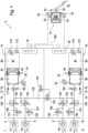
- the brake system 2 shown comprises four hydraulically actuated wheel brakes 4, 6, 8, 10, a pedal feel simulator or simulator 12, two Pressure supply devices 14, 16, two electronic control and regulating units 18, 20, a pressure medium reservoir under atmospheric pressure (not shown).
- the simulator 12 comprises a cylinder 22 in which an elastic simulator element 24 is arranged.
- a brake pedal 26 is connected to a simulator piston 32 via a piston rod 28 such that actuation of the brake pedal 26 from the rest position presses the simulator piston 32 against the simulator element 24, whereby the driver feels a counterforce. In this way, a pedal feel is simulated.
- the simulator 12 is dry, i.e. it does not comprise a pressure chamber filled with pressure medium.
- Two displacement sensors 40, 42 each preferably designed redundantly, measure the piston displacement of the piston 32 and the actuation displacement of the brake pedal 26, respectively.
- One of the two displacement sensors 40 is connected on the signal input side to a control and regulating unit 18.
- the other displacement sensor 42 is connected on the signal input side to the other control and regulating unit 20. This ensures that if one of the two sensors 40, 42 or one of the two control and regulating units 18, 20 fails, the driver's braking request can still be determined.
- Both pressure supply devices 14, 16 can be operated electrically and are designed as linear actuators. Both pressure supply devices 14, 16 each have an electric motor 60, the rotary movement of which is converted by means of a schematically indicated rotary-translation gear 62 into a translatory movement of a pressure piston 64, which is moved into a hydraulic pressure chamber 68 for the active pressure build-up in the wheel brakes 4-10.
- the pressure chambers 68 are each connected to the pressure medium reservoir 22 via an intake line 72 via a container connection 74, wherein a check valve 76 is arranged between the pressure chamber 68 and the intake line 72, which allows a flow of pressure medium from the pressure medium reservoir 22 into the pressure chamber 68 and in opposite direction.
- a pressure sensor preferably redundant, measures the pressure in the pressure chamber 68.
- the braking system 2 comprises two braking circuits I, II.
- a first braking circuit I comprises the wheel brakes 4, 6, a second braking circuit II comprises the wheel brakes 8, 10.
- the wheel brake 4 is the left front wheel brake
- wheel brake 6 is the right front wheel brake
- wheel brake 8 is the right rear wheel brake
- wheel brake 10 is the left rear wheel brake.
- the distribution of the wheel brakes 4-10 is therefore "black and white" or by axle.
- a normally open inlet valve 100 and a normally closed outlet valve 106 are arranged in a hydraulic connection between the pressure chamber 68 of the pressure supply device 14 and the wheel brake 4.
- a check valve 108 is connected in parallel to the inlet valve 100, which blocks a flow of pressure medium from the pressure chamber 68 in the direction of the wheel brake 4 and allows it in the opposite direction.
- the outlet valve is connected to the pressure medium reservoir via a container connection 110.
- an inlet valve 120 with a parallel check valve 122 and an outlet valve 124 with a container connection 126 are arranged in a hydraulic connection between the pressure chamber 69 of the pressure supply device 14.
- an inlet valve 130, 134 with a parallel check valve 132, 136 and an outlet valve 140, 144 with a reservoir connection 148, 150 are arranged in the same way in a connecting line between the pressure chamber 68 of the pressure supply device 16 and the respective wheel brake.
- the brake system 2 thus allows brake pressure to be built up and reduced for each wheel.
- the pressure chamber 68 of the pressure supply device 14 can be hydraulically connected to the wheel brakes 4,6 of the brake circuit I by a normally closed pressure connection valve 162.
- the pressure chamber 68 of the pressure supply device 16 can be hydraulically connected to the wheel brakes 4,6 of the brake circuit I by a normally closed pressure connection valve 162.
- Pressure control valve 164 can be hydraulically connected to the wheel brakes 8, 10 of the brake circuit.
- the pressure chamber 68 of the pressure supply device 14 is connected to the brake fluid reservoir or reservoir via a reservoir connection 70.
- the pressure chamber 68 of the pressure supply device 16 is also connected to the brake fluid reservoir or reservoir via a reservoir connection 78.
- the linear actuators therefore have sniffer holes with a reservoir connection that allow pressure and volume equalization to the reservoir for both brake circuits I, II in the actuator zero position. This is also the case for the wheel brakes 4, 6, 8, 10, since the actuator connection valves 162, 164 are open during operation or during a brake pressure position.
- the rotor position of the motor 60 is measured with the aid of a rotor position sensor 170, which is preferably designed redundantly.
- An optionally available, preferably designed redundantly sensor 172 measures the temperature of the motor winding.
- the rotor position of the motor 60 is measured with the aid of a rotor position sensor 170, which is preferably designed redundantly.
- An optionally available, preferably designed redundantly sensor 172 measures the temperature of the motor winding.
- the brake circuits I and II are hydraulically separable from one another.
- a normally closed circuit connection valve 152 is arranged in a hydraulic connecting line 150, to which a further normally closed circuit connection valve 154 is connected in parallel.
- the FIG.2 shows a preferred variant of a braking system with a hydraulically connected tandem master cylinder (THZ) 180, which is Brake pedal 26 can be actuated.
- the tandem master brake cylinder 180 comprises two pressure chambers 184, 186 arranged in a housing 182, namely the primary pressure chamber 184 and the secondary pressure chamber 186.
- the primary pressure chamber 184 is delimited by a primary piston 190 that can be actuated with the aid of the brake pedal 26, and the secondary chamber 186 is delimited by a floating secondary piston 194.
- the primary piston 190 is not actuated
- the primary pressure chamber 184 is connected to a brake fluid reservoir 200.
- the secondary piston 194 is not actuated, the secondary pressure chamber 18 is connected to the brake fluid reservoir 200.
- the simulator 12 is hydraulic. It can be hydraulically connected to the primary pressure chamber 184 by a simulator valve 202. In by-wire operation, the hydraulic connection of the tandem master brake cylinder 180 to the wheel brakes 4, 6, 8, 10 is shut off and a hydraulic connection to the simulator 12 is established. If both electronic units or control and regulating units are inactive, the driver can actuate the wheel brakes 4, 6, 8, 10 directly hydraulically.
- travel sensors 230, 232 are provided for measuring the pedal travel and/or the travel of the primary piston 190.
- Each of the two sensors 230, 232 is connected on the signal input side to another control and regulating unit 18, 20.
- This embodiment of the braking system 2 is also particularly required for vehicles that do not provide a redundant power supply for the two ECUs and pressure regulators, since in these cases, if an error occurs, namely the failure of the power supply, only hydraulic actuation by the driver is possible.
- FIG.3 shows a preferred embodiment of the brake system 2 with an asymmetric pressure regulator configuration.
- a pressure regulator or a pressure supply device 14 is designed as a linear actuator and a pressure supply device 240 as a combination of an electric motor-driven pump 244 and a pressure control valve 250.
- the pressure provided on the pump pressure side is measured by means of a pressure sensor 270, which is preferably designed redundantly.
- a connection valve 242 is also provided.
- the circuit separation of the brake circuits I, II is realized by series-connected, normally open solenoid valves or circuit separation valves 262, 264. In normal operation, these remain open and the linear actuator provides the system pressure for all wheel brakes 4, 6, 8, 10. While in the variants in FIG.1 and 2 the circuit separation is present in normal operation, it can be established here by closing one of the two circuit separation valves 262, 264 in order to obtain the advantageous functionalities described above.
- FIG.4 shows a preferred embodiment of the braking system 2 analogous to FIG.1 , but with pressure provision by means of two pumps 240, 280.
- both pressure provision devices are designed as pumps 240, 280.
- the circuit separation takes place as in FIG.1 shown by means of two parallel-connected, normally closed, circuit connection valves 152, 154.
Landscapes
- Engineering & Computer Science (AREA)
- Transportation (AREA)
- Mechanical Engineering (AREA)
- Physics & Mathematics (AREA)
- Fluid Mechanics (AREA)
- Regulating Braking Force (AREA)
- Valves And Accessory Devices For Braking Systems (AREA)
Claims (19)
- Système de freinage (2), comprenant quatre freins de roue (4, 6, 8, 10) actionnables hydrauliquement, une soupape d'admission (100, 120, 130, 134) ouverte sans courant étant associée à chaque frein de roue (4, 6, 8, 10), deux dispositifs de mise en pression (14, 16) étant prévus pour l'établissement actif de la pression dans les freins de roue (4, 6, 8, 10), une première (18) et une deuxième unité de commande et de régulation (20) étant prévues, un premier (I) et un deuxième circuit de freinage (II) étant réalisés hydrauliquement avec chacun deux freins de roue (4, 6 ; 8, 10), un dispositif de mise en pression (14, 16) étant relié hydrauliquement à deux freins de roue (4, 6 ; 8, 10) dans chaque circuit de freinage (I, II), la première unité de commande et de régulation (18) commandant électriquement le dispositif de mise en pression (14) du premier circuit de freinage (I) et la deuxième unité de commande et de régulation (20) commandant électriquement le dispositif de mise en pression (16) du deuxième circuit de freinage (II),
caractérisé en ce que
à chaque frein de roue (4, 6, 8, 10) est associée respectivement une soupape d'échappement (106, 124, 140, 144) fermée sans courant, en ce que les deux unités de commande et de régulation (18, 20) sont reliées l'une à l'autre par l'intermédiaire d'une interface de données (160) et en ce que les deux circuits de freinage (I, II) peuvent être reliés de manière hydrauliquement séparable à deux soupapes de connexion de circuit (152, 154) fermées sans courant, dont une première soupape de connexion de circuit (152) peut être commandée par la première unité de commande et de régulation, et une deuxième soupape de connexion de circuit (154) pouvant être commandée par la deuxième unité de commande et de régulation (20), au moins une soupape d'échappement (140, 144) dans le deuxième circuit de freinage (II) pouvant être commandée par la première unité de commande et de régulation (18) et au moins une soupape d'échappement (106, 124) dans le premier circuit de freinage (I) pouvant être commandée par la deuxième unité de commande et de régulation (20). - Système de freinage (2) selon la revendication 1, dans lequel exactement une soupape d'échappement (140, 144) dans le deuxième circuit de freinage (II) peut être commandée par la première unité de commande et de régulation (18) et dans lequel exactement une soupape d'échappement (106, 124) dans le premier circuit de freinage (I) peut être commandée par la deuxième unité de commande et de régulation (20).
- Système de freinage (2) selon la revendication 1 ou 2, dans lequel un simulateur de sensation de pédale (12) est prévu.
- Système de freinage (2) selon la revendication 3, dans lequel le simulateur de sensation de pédale (12) peut être actionné à l'aide d'une pédale de frein (26).
- Système de freinage (2) selon la revendication 4, dans lequel la pédale de frein (26) est couplée par une tige de couplage (28) à un piston de simulateur (32) déplaçable axialement, et dans lequel il est prévu deux capteurs de course (40, 42), réalisés notamment de manière redondante, qui mesurent chacun la course de piston et/ou la course de pédale parcourue.
- Système de freinage (2) selon la revendication 5, dans lequel un premier (40) des deux capteurs de course est relié côté entrée de signal à la première unité de commande et de régulation (18) et dans lequel un deuxième (42) des deux capteurs de course est relié côté entrée de signal à la deuxième unité de commande et de régulation (20).
- Système de freinage (2) selon l'une quelconque des revendications 1 à 6, dans lequel les deux dispositifs de mise en pression (14, 16) sont chacun réalisés sous forme d'actionneur linéaire.
- Système de freinage (2) selon l'une quelconque des revendications 1 à 6, dans lequel un dispositif de mise en pression (14) est réalisé sous forme d'actionneur linéaire et dans lequel l'autre dispositif de mise en pression est configuré sous forme de pompe.
- Système de freinage (2) selon l'une quelconque des revendications 1 à 8, dans lequel il est prévu deux réseaux de bord séparés, et dans lequel chaque dispositif de mise en pression (14, 16) est alimenté respectivement par l'un des deux réseaux de bord.
- Système de freinage (2) selon l'une quelconque des revendications 1 à 9, dans lequel la répartition hydraulique des freins de roue (4, 6, 8, 10) sur les deux circuits de freinage (I, II) est réalisée essieu par essieu.
- Système de freinage (2) selon l'une quelconque des revendications 1 à 10, dans lequel un maître-cylindre de frein est relié de manière hydrauliquement séparable aux freins de roue (4, 6, 8, 10).
- Système de freinage (2) selon l'une quelconque des revendications 1 à 11, dans lequel les deux soupapes de connexion de circuit (152, 154) sont connectées en parallèle.
- Procédé d'exploitation d'un système de freinage (2) selon l'une quelconque des revendications 1 à 12, dans lequel, en cas de défaillance électrique d'un circuit de freinage (I, II), la régulation de pression est effectuée dans ce circuit de freinage défaillant (I, II) par commande d'une soupape de connexion de circuit (152, 154) et d'une soupape d'échappement (106, 124, 140, 144) par l'unité de commande et de régulation (18, 20) dans le circuit de freinage intact (I, II), et dans lequel la régulation de pression dans le circuit de freinage électriquement intact (II, I) est effectuée à l'aide de deux soupapes d'admission (100, 120, 130, 134) et d'une soupape d'échappement (106, 124, 140, 144).
- Procédé selon la revendication 13, dans lequel, pour établir la pression dans le circuit de freinage (I, II) défaillant, une pression préliminaire est établie dans le circuit de freinage (I, II) intact par l'unité de mise en pression (14, 16) intacte, une soupape de connexion de circuit étant ouverte (152, 154), de telle sorte que du liquide de frein s'écoule dans le circuit de freinage (I, II) défaillant.
- Procédé selon la revendication 13 ou 14, dans lequel, pour réduire la pression dans le circuit de freinage (I, II) défaillant, une soupape d'échappement (106, 124, 140, 144) dans le circuit de freinage (I ; II) défaillant est ouverte par l'unité de commande et de régulation (18, 20) intacte.
- Procédé selon l'une quelconque des revendications 13 à 15, dans lequel, pour établir la pression dans le circuit de freinage intact (I, II), on fait passer du liquide de frein de la chambre de pression (68) du dispositif de mise en pression (14, 16) à travers au moins une soupape d'admission (100, 120, 130, 134) dans un frein de roue (4, 6, 8, 10).
- Procédé selon l'une quelconque des revendications 13 à 16, dans lequel, pour réduire la pression dans le circuit de freinage intact (I, II), une soupape d'échappement (106, 124, 140, 144) est commandée par l'unité de commande et de régulation (18, 20) du circuit de freinage intact (I, II) et dans lequel la soupape d'admission (100, 120, 130, 134) du frein de roue (4, 6, 8, 10) est ouverte, à laquelle est associée la soupape d'échappement (106, 124, 140, 144) commandée par l'unité de commande et de régulation (18, 20) du circuit de freinage intact (I, II).
- Procédé selon la revendication 17, dans lequel on ouvre en outre la soupape d'admission (100, 120, 130, 134) du frein de roue (4, 6, 8, 10) qui est associée au frein de roue (4, 6, 8, 10) avec la soupape d'échappement (106, 124, 140, 144) commandée par l'unité de commande et de régulation (18, 20) du circuit de freinage (I, II) défaillant.
- Procédé selon la revendication 17 ou 18, dans lequel le dispositif de mise en pression (14, 16) est configuré sous forme d'actionneur linéaire et dans lequel la position du piston de l'actionneur est maintenue pendant la réduction de la pression.
Applications Claiming Priority (2)
| Application Number | Priority Date | Filing Date | Title |
|---|---|---|---|
| DE102018208223.5A DE102018208223A1 (de) | 2018-05-24 | 2018-05-24 | Bremssystem mit zwei Druckquellen und Verfahren zum Betreiben eines Bremssystems mit zwei Druckquellen |
| PCT/EP2019/062509 WO2019224077A1 (fr) | 2018-05-24 | 2019-05-15 | Système de freinage muni de deux sources de pression et procédé permettant de faire fonctionner un système de freinage muni de deux sources de pression |
Publications (2)
| Publication Number | Publication Date |
|---|---|
| EP3802247A1 EP3802247A1 (fr) | 2021-04-14 |
| EP3802247B1 true EP3802247B1 (fr) | 2024-09-11 |
Family
ID=66597575
Family Applications (1)
| Application Number | Title | Priority Date | Filing Date |
|---|---|---|---|
| EP19725101.0A Active EP3802247B1 (fr) | 2018-05-24 | 2019-05-15 | Système de freinage muni de deux sources de pression et procédé permettant de faire fonctionner un système de freinage muni de deux sources de pression |
Country Status (6)
| Country | Link |
|---|---|
| US (1) | US11999326B2 (fr) |
| EP (1) | EP3802247B1 (fr) |
| KR (1) | KR102479868B1 (fr) |
| CN (1) | CN112188976B (fr) |
| DE (1) | DE102018208223A1 (fr) |
| WO (1) | WO2019224077A1 (fr) |
Families Citing this family (59)
| Publication number | Priority date | Publication date | Assignee | Title |
|---|---|---|---|---|
| DE102017219598A1 (de) * | 2017-01-11 | 2018-07-12 | Continental Teves Ag & Co. Ohg | Bremsanlage für Kraftfahrzeuge sowie Verfahren zum Betrieb einer Bremsanlage |
| DE102017216617A1 (de) * | 2017-09-20 | 2019-03-21 | Continental Teves Ag & Co. Ohg | Bremsanlage für ein Kraftfahrzeug sowie Verfahren zu deren Betrieb |
| DE102017218999A1 (de) * | 2017-10-24 | 2019-04-25 | Continental Teves Ag & Co. Ohg | Bremsanlage und Verfahren zum Betrieb einer solchen Bremsanlage |
| DE102017219000A1 (de) * | 2017-10-24 | 2019-04-25 | Continental Teves Ag & Co. Ohg | Bremsanlage und Verfahren zum Betrieb einer solchen Bremsanlage |
| US20210155215A1 (en) * | 2018-04-04 | 2021-05-27 | ZF Active Safety US Inc. | Vehicle brake system with secondary brake module |
| DE102018212279A1 (de) * | 2018-07-24 | 2020-01-30 | Robert Bosch Gmbh | Verfahren zum Betreiben eines Bremssystems sowie Bremssystem |
| KR102620657B1 (ko) * | 2019-01-03 | 2024-01-03 | 현대모비스 주식회사 | 차량의 제동장치 및 그 제어방법 |
| US12071118B2 (en) | 2019-02-12 | 2024-08-27 | Ipgate Ag | Pressure supply device with double stroke piston for a brake system |
| DE202019101586U1 (de) * | 2019-02-12 | 2020-05-13 | Ipgate Ag | Packaging für ein Bremssystem |
| JP2022520243A (ja) | 2019-02-12 | 2022-03-29 | アイピーゲート・アクチェンゲゼルシャフト | フェールセーフブレーキシステム |
| DE102019103464A1 (de) | 2019-02-12 | 2020-08-13 | Ipgate Ag | Hydrauliksystem mit mindestens zwei hydraulischen Kreisen und mindestens zwei Druckversorgungseinrichtungen |
| DE202019101596U1 (de) | 2019-02-12 | 2020-05-13 | Ipgate Ag | Hydrauliksystem mit mindestens zwei hydraulischen Kreisen und mindestens zwei Druckversorgungseinrichtungen |
| CN113631443B (zh) | 2019-02-12 | 2024-02-23 | 爱皮加特股份公司 | 具有压力供给装置和用于制动回路的安全门的制动系统 |
| DE102019201907A1 (de) * | 2019-02-14 | 2020-08-20 | Robert Bosch Gmbh | Elektronisch schlupfregelbare Fremdkraftbremsanlage |
| EP4382375B1 (fr) * | 2019-03-06 | 2025-10-29 | HL Mando Corporation | Système de freinage |
| KR102670916B1 (ko) * | 2019-03-12 | 2024-05-30 | 에이치엘만도 주식회사 | 전자식 브레이크 시스템 및 작동방법 |
| KR102643094B1 (ko) * | 2019-04-18 | 2024-03-04 | 현대모비스 주식회사 | 전자식 유압 브레이크 장치 및 그의 제어 방법 |
| DE102019211537A1 (de) * | 2019-08-01 | 2021-02-04 | Robert Bosch Gmbh | Hydraulisches Bremssystem für ein Kraftfahrzeug, Verfahren zum Betreiben |
| CN115366854A (zh) * | 2019-09-30 | 2022-11-22 | 华为技术有限公司 | 汽车的分布式制动系统、汽车及其控制方法 |
| DE102019215360A1 (de) * | 2019-10-08 | 2021-04-08 | Continental Teves Ag & Co. Ohg | Verfahren zum Betreiben eines Bremssystems, Bremssystem, Kraftfahrzeug und Speichermedium |
| JP7491001B2 (ja) * | 2020-03-19 | 2024-05-28 | 株式会社アドヴィックス | 車両用制動装置 |
| JP7424165B2 (ja) * | 2020-03-30 | 2024-01-30 | 株式会社アドヴィックス | 車両用制動装置 |
| US11912251B2 (en) * | 2020-06-25 | 2024-02-27 | Hl Mando Corporation | Electric brake system |
| JP2023533332A (ja) * | 2020-07-10 | 2023-08-02 | 華為技術有限公司 | 車両制動用ブレーキシステム及び自動運転車両 |
| KR102880903B1 (ko) * | 2020-08-14 | 2025-11-04 | 현대자동차주식회사 | 브레이크 시스템 |
| WO2022116078A1 (fr) * | 2020-12-03 | 2022-06-09 | 华为技术有限公司 | Unité de régulation hydraulique, système de freinage intégré et procédé de commande |
| US11767003B2 (en) * | 2020-12-14 | 2023-09-26 | Continental Automotive Systems, Inc. | By-wire brake system for motor vehicles |
| GB2602157A (en) * | 2020-12-21 | 2022-06-22 | Airbus Operations Ltd | Braking system |
| DE102021100921A1 (de) | 2021-01-18 | 2022-07-21 | Audi Aktiengesellschaft | Elektrohydraulischer Achsmomentensteller |
| DE102021108524A1 (de) | 2021-04-06 | 2022-10-06 | Audi Aktiengesellschaft | Bremssystem für ein autonomes Fahrzeug |
| US11904820B2 (en) * | 2021-07-02 | 2024-02-20 | ZF Active Safety US Inc. | Apparatus and method for control of a hydraulic brake by wire system |
| DE102021207277A1 (de) | 2021-07-09 | 2023-01-12 | Continental Automotive Technologies GmbH | Bremssystem für ein Kraftfahrzeug |
| JP7537388B2 (ja) | 2021-07-16 | 2024-08-21 | 株式会社デンソー | ブレーキシステム |
| CN113561953B (zh) * | 2021-07-27 | 2022-11-25 | 中国北方车辆研究所 | 一种重载车辆线控冗余制动操纵系统及其容错控制方法 |
| WO2023010297A1 (fr) * | 2021-08-03 | 2023-02-09 | 华为技术有限公司 | Système de freinage, dispositif hydraulique et véhicule |
| US12311902B2 (en) * | 2021-08-12 | 2025-05-27 | ZF Active Safety US Inc. | Apparatus and method for control of a hydraulic brake system |
| US11951970B2 (en) * | 2021-08-12 | 2024-04-09 | ZF Active Safety US Inc. | Brake system with plunger-based secondary brake module |
| JP7655826B2 (ja) * | 2021-09-09 | 2025-04-02 | 日立Astemo株式会社 | ブレーキ装置 |
| KR20230058958A (ko) * | 2021-10-25 | 2023-05-03 | 현대모비스 주식회사 | 전자식 유압 브레이크 |
| KR20230065815A (ko) * | 2021-11-05 | 2023-05-12 | 현대모비스 주식회사 | 전자식 유압 브레이크 |
| CN113954803A (zh) * | 2021-11-29 | 2022-01-21 | 万向钱潮股份有限公司 | 一种大型车辆电子制动助力系统 |
| DE102021213709A1 (de) | 2021-12-02 | 2023-06-07 | Continental Automotive Technologies GmbH | Verfahren zum Nachfüllen eines Primärdruckerzeugers in einer elektrohydraulischen Bremsanlage und elektrohydraulische Bremsanlage |
| US12145563B2 (en) | 2021-12-08 | 2024-11-19 | ZF Active Safety US Inc. | Apparatus and method for a hydraulic brake system including manual push-through |
| US12115960B2 (en) | 2021-12-15 | 2024-10-15 | ZF Active Safety US Inc. | Apparatus and method for a hydraulic brake system including manual push-through |
| CN114291062B (zh) * | 2021-12-30 | 2023-01-10 | 深兰人工智能(深圳)有限公司 | 线控制动系统、线控制动方法及包括线控制动系统的车辆 |
| US12240427B2 (en) | 2022-03-30 | 2025-03-04 | ZF Active Safety US Inc. | Fast replenishing brake system |
| KR102658541B1 (ko) * | 2022-06-13 | 2024-04-18 | 현대모비스 주식회사 | 전자식 유압 브레이크 장치 |
| US20260001519A1 (en) * | 2022-07-11 | 2026-01-01 | Hitachi Astemo, Ltd. | Brake device |
| DE102022212111A1 (de) * | 2022-11-15 | 2024-05-16 | Continental Automotive Technologies GmbH | Druckhalten in redundanten Bremssystemen |
| DE102022212915A1 (de) * | 2022-11-30 | 2024-06-06 | Robert Bosch Gesellschaft mit beschränkter Haftung | Hydraulische Bremsanlage eines Fahrzeugs, Fahrzeug, Verfahren zum Betreiben einer hydraulischen Bremsanlage eines Fahrzeugs |
| CN118107535A (zh) * | 2022-11-30 | 2024-05-31 | 比亚迪汽车工业有限公司 | 车辆制动系统和具有其的车辆 |
| DE102022213129A1 (de) | 2022-12-06 | 2024-06-06 | Continental Automotive Technologies GmbH | Elektrohydraulisches Bremsensteuergerät für ein Kraftfahrzeug und Verfahren zum Betreiben eines solchen Bremsensteuergeräts |
| WO2025070449A1 (fr) * | 2023-09-26 | 2025-04-03 | 日立Astemo株式会社 | Système de frein |
| CN121816296A (zh) * | 2023-09-26 | 2026-04-07 | 安斯泰莫株式会社 | 制动系统 |
| DE102024102956A1 (de) * | 2024-02-02 | 2025-08-07 | Zf Active Safety Gmbh | Fehlertolerantes Bremssystem für ein Kraftfahrzeug |
| WO2025180886A1 (fr) * | 2024-02-27 | 2025-09-04 | Zf Cv Systems Global Gmbh | Véhicule et procédé de conduite d'un véhicule |
| DE102024206170A1 (de) | 2024-07-02 | 2026-01-08 | Continental Automotive Technologies GmbH | Bremssystem mit zwei achsindividuellen Druckquellen |
| DE102024206586A1 (de) * | 2024-07-12 | 2026-01-15 | Robert Bosch Gesellschaft mit beschränkter Haftung | Verfahren zur Erkennung einer Leckage in einem Fremdkraftbremssystem |
| JP2026014397A (ja) * | 2024-07-19 | 2026-01-29 | Astemo株式会社 | ブレーキ制御装置 |
Citations (1)
| Publication number | Priority date | Publication date | Assignee | Title |
|---|---|---|---|---|
| DE102016203563A1 (de) * | 2016-03-04 | 2017-09-07 | Continental Teves Ag & Co. Ohg | Bremsanlage mit zwei Druckbereitstellungseinrichtungen sowie Verfahren zum Betreiben einer Bremsanlage |
Family Cites Families (30)
| Publication number | Priority date | Publication date | Assignee | Title |
|---|---|---|---|---|
| DE19717686A1 (de) | 1997-04-28 | 1998-10-29 | Itt Mfg Enterprises Inc | Schaltungsanordnung für ein Kraftfahrzeug-Regelungssystem |
| DE10036287B4 (de) * | 2000-07-26 | 2009-07-30 | Robert Bosch Gmbh | Verfahren und Vorrichtung zur Steuerung von Radbremsen |
| DE10319338A1 (de) * | 2003-04-30 | 2004-11-18 | Daimlerchrysler Ag | Bremsanlage für Fahrzeuge |
| JP4369198B2 (ja) | 2003-10-10 | 2009-11-18 | 株式会社ジェイテクト | 車両用操舵制御装置 |
| US9340193B2 (en) * | 2009-02-03 | 2016-05-17 | Kelsey-Hayes Company | Vehicle brake system |
| DE102010040097A1 (de) * | 2009-09-11 | 2011-03-31 | Continental Teves Ag & Co. Ohg | Bremsanlage für Kraftfahrzeuge |
| DE102011076675A1 (de) * | 2010-06-10 | 2011-12-15 | Continental Teves Ag & Co. Ohg | Verfahren und Vorrichtung zur Regelung eines elektrohydraulischen Bremssystems für Kraftfahrzeuge |
| DE102012205862A1 (de) * | 2011-04-19 | 2012-10-25 | Continental Teves Ag & Co. Ohg | Bremsanlage für Kraftfahrzeuge sowie Verfahren zum Betrieb einer Bremsanlage |
| DE102012205962A1 (de) * | 2011-05-05 | 2012-11-08 | Continental Teves Ag & Co. Ohg | Bremsanlage für Kraftfahrzeuge sowie Verfahren zum Betrieb einer Bremsanlage |
| DE102011122776A1 (de) | 2011-07-21 | 2013-01-24 | Daimler Ag | Bremsanlage für ein Kraftfahrzeug |
| DE102012210809A1 (de) | 2011-07-27 | 2013-01-31 | Continental Teves Ag & Co. Ohg | Bremsanlage für Kraftfahrzeuge sowie Verfahren zum Betrieb einer Bremsanlage |
| DE102012222897A1 (de) * | 2012-02-28 | 2013-08-29 | Continental Teves Ag & Co. Ohg | Verfahren zum Betrieb einer Bremsanlage |
| DE102013204778B4 (de) * | 2012-03-22 | 2026-03-26 | Aumovio Germany Gmbh | Verfahren zur haptischen Information des Fahrers eines Kraftfahrzeugs |
| DE102013225809A1 (de) * | 2013-02-27 | 2014-08-28 | Continental Teves Ag & Co. Ohg | Bremsanlage für Kraftfahrzeuge |
| DE102013224870A1 (de) * | 2013-03-05 | 2014-09-11 | Continental Teves Ag & Co. Ohg | Bremsbetätigungseinheit |
| DE102013014188A1 (de) * | 2013-08-26 | 2015-02-26 | Lucas Automotive Gmbh | Elektrohydraulische Fahrzeug-Bremsanlage mit elektromechanischem Aktuator und Verfahren zum Betreiben der Bremsanlage |
| DE102013217954A1 (de) * | 2013-09-09 | 2015-03-12 | Continental Teves Ag & Co. Ohg | Bremsanlage für ein Kraftfahrzeug und Betriebsverfahren |
| DE102014212537A1 (de) * | 2014-06-30 | 2015-12-31 | Continental Teves Ag & Co. Ohg | Bremsanlage für ein Kraftfahrzeug |
| US10166964B2 (en) * | 2014-07-10 | 2019-01-01 | Continental Automotive Systems, Inc. | Pedalless electronically controlled hydraulic braking system with redundant pump |
| DE102014225958A1 (de) * | 2014-12-16 | 2016-06-16 | Continental Teves Ag & Co. Ohg | Bremsanlage für ein Kraftfahrzeug |
| DE102016213994A1 (de) * | 2016-07-29 | 2018-02-01 | Continental Teves Ag & Co. Ohg | Bremssystem und Verfahren zum Betreiben eines Bremssystems |
| DE102016225537A1 (de) * | 2016-12-20 | 2018-06-21 | Continental Teves Ag & Co. Ohg | Bremssystem mit zwei Druckquellen und Verfahren zum Betreiben eines Bremssystems |
| DE102017222445A1 (de) * | 2017-01-11 | 2018-07-12 | Continental Teves Ag & Co. Ohg | Bremsanlage für ein Kraftfahrzeug und Verfahren zum Betrieb einer Bremsanlage |
| US20180290640A1 (en) * | 2017-04-06 | 2018-10-11 | Ford Global Technologies, Llc | Methods and apparatus to control vehicle braking systems |
| DE102017216617A1 (de) * | 2017-09-20 | 2019-03-21 | Continental Teves Ag & Co. Ohg | Bremsanlage für ein Kraftfahrzeug sowie Verfahren zu deren Betrieb |
| US20200307538A1 (en) * | 2017-11-29 | 2020-10-01 | Zf Active Safey Us Inc. | Brake system with multiple pressure sources |
| US11866025B2 (en) * | 2017-12-20 | 2024-01-09 | Brembo S.P.A. | Brake-by-wire braking system for vehicles |
| DE102018217663A1 (de) * | 2018-10-15 | 2020-04-16 | Continental Teves Ag & Co. Ohg | Verfahren zum Bestimmen eines Schaltzustands eines Ventils und Elektromagnetventilanordnung |
| DE102019211537A1 (de) * | 2019-08-01 | 2021-02-04 | Robert Bosch Gmbh | Hydraulisches Bremssystem für ein Kraftfahrzeug, Verfahren zum Betreiben |
| DE102019214792B4 (de) * | 2019-09-26 | 2025-09-11 | Continental Automotive Technologies GmbH | Bremssystem und Kraftfahrzeug |
-
2018
- 2018-05-24 DE DE102018208223.5A patent/DE102018208223A1/de active Pending
-
2019
- 2019-05-15 KR KR1020207033537A patent/KR102479868B1/ko active Active
- 2019-05-15 EP EP19725101.0A patent/EP3802247B1/fr active Active
- 2019-05-15 WO PCT/EP2019/062509 patent/WO2019224077A1/fr not_active Ceased
- 2019-05-15 US US17/054,672 patent/US11999326B2/en active Active
- 2019-05-15 CN CN201980034637.3A patent/CN112188976B/zh active Active
Patent Citations (1)
| Publication number | Priority date | Publication date | Assignee | Title |
|---|---|---|---|---|
| DE102016203563A1 (de) * | 2016-03-04 | 2017-09-07 | Continental Teves Ag & Co. Ohg | Bremsanlage mit zwei Druckbereitstellungseinrichtungen sowie Verfahren zum Betreiben einer Bremsanlage |
Also Published As
| Publication number | Publication date |
|---|---|
| WO2019224077A1 (fr) | 2019-11-28 |
| CN112188976A (zh) | 2021-01-05 |
| US11999326B2 (en) | 2024-06-04 |
| CN112188976B (zh) | 2023-07-04 |
| KR20210003194A (ko) | 2021-01-11 |
| DE102018208223A1 (de) | 2019-11-28 |
| EP3802247A1 (fr) | 2021-04-14 |
| KR102479868B1 (ko) | 2022-12-21 |
| US20210053540A1 (en) | 2021-02-25 |
Similar Documents
| Publication | Publication Date | Title |
|---|---|---|
| EP3802247B1 (fr) | Système de freinage muni de deux sources de pression et procédé permettant de faire fonctionner un système de freinage muni de deux sources de pression | |
| EP3558771B1 (fr) | Système de freinage doté de deux sources d'air comprimé et deux procédés de fonctionnement d'un système de freinage | |
| EP2707262B1 (fr) | Système de freinage hydraulique de véhicule comprenant un actionneur électromécanique et procédé permettant de faire fonctionner un tel système de freinage hydraulique de véhicule | |
| EP3700785B1 (fr) | Système de freinage et procédé pour faire fonctionner un tel système de freinage | |
| DE102013227065B4 (de) | Hydraulisches Bremssystem mit erstem und zweitem Bremsdruckerzeuger sowie Verfahren zum Betreiben eines Bremssystems | |
| EP3684659A1 (fr) | Système de freinage pour véhicule automobile et procédé de fonctionnement de celui-ci | |
| WO2018210534A1 (fr) | Système de freinage et procédé pour faire fonctionner un système de freinage | |
| DE102017222445A1 (de) | Bremsanlage für ein Kraftfahrzeug und Verfahren zum Betrieb einer Bremsanlage | |
| DE102017215704B4 (de) | Bremssystem für Fahrzeug | |
| WO2017144201A1 (fr) | Module additionnel pour système de freinage électrohydraulique et ensemble système de freinage comprenant un module additionnel de ce type | |
| DE102011081461A1 (de) | Bremsanlage für Kraftfahrzeuge | |
| WO2014131645A1 (fr) | Système de freinage pour véhicules automobiles | |
| DE102017222450A1 (de) | Bremsanlage für ein Kraftfahrzeug | |
| DE102019207057A1 (de) | Bremsanlage für ein Kraftfahrzeug und Verfahren zum Betreiben der Bremsanlage | |
| DE102017222440A1 (de) | Bremsanlage für ein Kraftfahrzeug sowie Verfahren zu deren Betrieb | |
| DE102017222435A1 (de) | Bremsanlage für ein Kraftfahrzeug sowie Verfahren zu deren Betrieb | |
| DE102011081463A1 (de) | Bremsanlage für Kraftfahrzeuge | |
| EP2822823B1 (fr) | Procédé de fonctionnement d'un système hydraulique et système de freinage | |
| DE102021213466A1 (de) | Einfahrbares Bremspedal | |
| DE102021206803A1 (de) | Hydraulischer Kommunikationskanal | |
| DE102022213133A1 (de) | Elektronisch schlupfregelbare Fremdkraftbremsanlage | |
| DE102017211807A1 (de) | Bremssystem mit primärer Bremsregeleinrichtung und Zusatzmodul | |
| DE102016222845A1 (de) | Bremssystem für ein Kraftfahrzeug sowie Verfahren zum Betreiben eines Bremssystems | |
| WO2023227173A1 (fr) | Système de freinage pour véhicules automobiles pourvu d'un dispositif d'alimentation en pression | |
| WO2018224457A1 (fr) | Système de freinage et deux procédés pour faire fonctionner le système de freinage |
Legal Events
| Date | Code | Title | Description |
|---|---|---|---|
| STAA | Information on the status of an ep patent application or granted ep patent |
Free format text: STATUS: UNKNOWN |
|
| STAA | Information on the status of an ep patent application or granted ep patent |
Free format text: STATUS: THE INTERNATIONAL PUBLICATION HAS BEEN MADE |
|
| PUAI | Public reference made under article 153(3) epc to a published international application that has entered the european phase |
Free format text: ORIGINAL CODE: 0009012 |
|
| STAA | Information on the status of an ep patent application or granted ep patent |
Free format text: STATUS: REQUEST FOR EXAMINATION WAS MADE |
|
| 17P | Request for examination filed |
Effective date: 20210111 |
|
| AK | Designated contracting states |
Kind code of ref document: A1 Designated state(s): AL AT BE BG CH CY CZ DE DK EE ES FI FR GB GR HR HU IE IS IT LI LT LU LV MC MK MT NL NO PL PT RO RS SE SI SK SM TR |
|
| AX | Request for extension of the european patent |
Extension state: BA ME |
|
| DAV | Request for validation of the european patent (deleted) | ||
| DAX | Request for extension of the european patent (deleted) | ||
| RAP1 | Party data changed (applicant data changed or rights of an application transferred) |
Owner name: CONTINENTAL AUTOMOTIVE TECHNOLOGIES GMBH |
|
| STAA | Information on the status of an ep patent application or granted ep patent |
Free format text: STATUS: EXAMINATION IS IN PROGRESS |
|
| 17Q | First examination report despatched |
Effective date: 20221206 |
|
| RAP3 | Party data changed (applicant data changed or rights of an application transferred) |
Owner name: CONTINENTAL AUTOMOTIVE TECHNOLOGIES GMBH |
|
| GRAP | Despatch of communication of intention to grant a patent |
Free format text: ORIGINAL CODE: EPIDOSNIGR1 |
|
| STAA | Information on the status of an ep patent application or granted ep patent |
Free format text: STATUS: GRANT OF PATENT IS INTENDED |
|
| INTG | Intention to grant announced |
Effective date: 20240502 |
|
| GRAS | Grant fee paid |
Free format text: ORIGINAL CODE: EPIDOSNIGR3 |
|
| GRAA | (expected) grant |
Free format text: ORIGINAL CODE: 0009210 |
|
| STAA | Information on the status of an ep patent application or granted ep patent |
Free format text: STATUS: THE PATENT HAS BEEN GRANTED |
|
| AK | Designated contracting states |
Kind code of ref document: B1 Designated state(s): AL AT BE BG CH CY CZ DE DK EE ES FI FR GB GR HR HU IE IS IT LI LT LU LV MC MK MT NL NO PL PT RO RS SE SI SK SM TR |
|
| REG | Reference to a national code |
Ref country code: GB Ref legal event code: FG4D Free format text: NOT ENGLISH |
|
| REG | Reference to a national code |
Ref country code: CH Ref legal event code: EP |
|
| REG | Reference to a national code |
Ref country code: DE Ref legal event code: R096 Ref document number: 502019012106 Country of ref document: DE |
|
| REG | Reference to a national code |
Ref country code: IE Ref legal event code: FG4D Free format text: LANGUAGE OF EP DOCUMENT: GERMAN |
|
| REG | Reference to a national code |
Ref country code: LT Ref legal event code: MG9D |
|
| PG25 | Lapsed in a contracting state [announced via postgrant information from national office to epo] |
Ref country code: NO Free format text: LAPSE BECAUSE OF FAILURE TO SUBMIT A TRANSLATION OF THE DESCRIPTION OR TO PAY THE FEE WITHIN THE PRESCRIBED TIME-LIMIT Effective date: 20241211 |
|
| REG | Reference to a national code |
Ref country code: NL Ref legal event code: MP Effective date: 20240911 |
|
| PG25 | Lapsed in a contracting state [announced via postgrant information from national office to epo] |
Ref country code: GR Free format text: LAPSE BECAUSE OF FAILURE TO SUBMIT A TRANSLATION OF THE DESCRIPTION OR TO PAY THE FEE WITHIN THE PRESCRIBED TIME-LIMIT Effective date: 20241212 Ref country code: FI Free format text: LAPSE BECAUSE OF FAILURE TO SUBMIT A TRANSLATION OF THE DESCRIPTION OR TO PAY THE FEE WITHIN THE PRESCRIBED TIME-LIMIT Effective date: 20240911 |
|
| PG25 | Lapsed in a contracting state [announced via postgrant information from national office to epo] |
Ref country code: BG Free format text: LAPSE BECAUSE OF FAILURE TO SUBMIT A TRANSLATION OF THE DESCRIPTION OR TO PAY THE FEE WITHIN THE PRESCRIBED TIME-LIMIT Effective date: 20240911 |
|
| PG25 | Lapsed in a contracting state [announced via postgrant information from national office to epo] |
Ref country code: LV Free format text: LAPSE BECAUSE OF FAILURE TO SUBMIT A TRANSLATION OF THE DESCRIPTION OR TO PAY THE FEE WITHIN THE PRESCRIBED TIME-LIMIT Effective date: 20240911 |
|
| PG25 | Lapsed in a contracting state [announced via postgrant information from national office to epo] |
Ref country code: HR Free format text: LAPSE BECAUSE OF FAILURE TO SUBMIT A TRANSLATION OF THE DESCRIPTION OR TO PAY THE FEE WITHIN THE PRESCRIBED TIME-LIMIT Effective date: 20240911 |
|
| PG25 | Lapsed in a contracting state [announced via postgrant information from national office to epo] |
Ref country code: RS Free format text: LAPSE BECAUSE OF FAILURE TO SUBMIT A TRANSLATION OF THE DESCRIPTION OR TO PAY THE FEE WITHIN THE PRESCRIBED TIME-LIMIT Effective date: 20241211 Ref country code: ES Free format text: LAPSE BECAUSE OF FAILURE TO SUBMIT A TRANSLATION OF THE DESCRIPTION OR TO PAY THE FEE WITHIN THE PRESCRIBED TIME-LIMIT Effective date: 20240911 |
|
| PG25 | Lapsed in a contracting state [announced via postgrant information from national office to epo] |
Ref country code: RS Free format text: LAPSE BECAUSE OF FAILURE TO SUBMIT A TRANSLATION OF THE DESCRIPTION OR TO PAY THE FEE WITHIN THE PRESCRIBED TIME-LIMIT Effective date: 20241211 Ref country code: NO Free format text: LAPSE BECAUSE OF FAILURE TO SUBMIT A TRANSLATION OF THE DESCRIPTION OR TO PAY THE FEE WITHIN THE PRESCRIBED TIME-LIMIT Effective date: 20241211 Ref country code: LV Free format text: LAPSE BECAUSE OF FAILURE TO SUBMIT A TRANSLATION OF THE DESCRIPTION OR TO PAY THE FEE WITHIN THE PRESCRIBED TIME-LIMIT Effective date: 20240911 Ref country code: HR Free format text: LAPSE BECAUSE OF FAILURE TO SUBMIT A TRANSLATION OF THE DESCRIPTION OR TO PAY THE FEE WITHIN THE PRESCRIBED TIME-LIMIT Effective date: 20240911 Ref country code: GR Free format text: LAPSE BECAUSE OF FAILURE TO SUBMIT A TRANSLATION OF THE DESCRIPTION OR TO PAY THE FEE WITHIN THE PRESCRIBED TIME-LIMIT Effective date: 20241212 Ref country code: FI Free format text: LAPSE BECAUSE OF FAILURE TO SUBMIT A TRANSLATION OF THE DESCRIPTION OR TO PAY THE FEE WITHIN THE PRESCRIBED TIME-LIMIT Effective date: 20240911 Ref country code: ES Free format text: LAPSE BECAUSE OF FAILURE TO SUBMIT A TRANSLATION OF THE DESCRIPTION OR TO PAY THE FEE WITHIN THE PRESCRIBED TIME-LIMIT Effective date: 20240911 Ref country code: BG Free format text: LAPSE BECAUSE OF FAILURE TO SUBMIT A TRANSLATION OF THE DESCRIPTION OR TO PAY THE FEE WITHIN THE PRESCRIBED TIME-LIMIT Effective date: 20240911 |
|
| PG25 | Lapsed in a contracting state [announced via postgrant information from national office to epo] |
Ref country code: NL Free format text: LAPSE BECAUSE OF FAILURE TO SUBMIT A TRANSLATION OF THE DESCRIPTION OR TO PAY THE FEE WITHIN THE PRESCRIBED TIME-LIMIT Effective date: 20240911 |
|
| PG25 | Lapsed in a contracting state [announced via postgrant information from national office to epo] |
Ref country code: PT Free format text: LAPSE BECAUSE OF FAILURE TO SUBMIT A TRANSLATION OF THE DESCRIPTION OR TO PAY THE FEE WITHIN THE PRESCRIBED TIME-LIMIT Effective date: 20250113 Ref country code: IS Free format text: LAPSE BECAUSE OF FAILURE TO SUBMIT A TRANSLATION OF THE DESCRIPTION OR TO PAY THE FEE WITHIN THE PRESCRIBED TIME-LIMIT Effective date: 20250111 |
|
| PG25 | Lapsed in a contracting state [announced via postgrant information from national office to epo] |
Ref country code: RO Free format text: LAPSE BECAUSE OF FAILURE TO SUBMIT A TRANSLATION OF THE DESCRIPTION OR TO PAY THE FEE WITHIN THE PRESCRIBED TIME-LIMIT Effective date: 20240911 Ref country code: SM Free format text: LAPSE BECAUSE OF FAILURE TO SUBMIT A TRANSLATION OF THE DESCRIPTION OR TO PAY THE FEE WITHIN THE PRESCRIBED TIME-LIMIT Effective date: 20240911 |
|
| PG25 | Lapsed in a contracting state [announced via postgrant information from national office to epo] |
Ref country code: EE Free format text: LAPSE BECAUSE OF FAILURE TO SUBMIT A TRANSLATION OF THE DESCRIPTION OR TO PAY THE FEE WITHIN THE PRESCRIBED TIME-LIMIT Effective date: 20240911 |
|
| PG25 | Lapsed in a contracting state [announced via postgrant information from national office to epo] |
Ref country code: CZ Free format text: LAPSE BECAUSE OF FAILURE TO SUBMIT A TRANSLATION OF THE DESCRIPTION OR TO PAY THE FEE WITHIN THE PRESCRIBED TIME-LIMIT Effective date: 20240911 Ref country code: PL Free format text: LAPSE BECAUSE OF FAILURE TO SUBMIT A TRANSLATION OF THE DESCRIPTION OR TO PAY THE FEE WITHIN THE PRESCRIBED TIME-LIMIT Effective date: 20240911 |
|
| PG25 | Lapsed in a contracting state [announced via postgrant information from national office to epo] |
Ref country code: IT Free format text: LAPSE BECAUSE OF FAILURE TO SUBMIT A TRANSLATION OF THE DESCRIPTION OR TO PAY THE FEE WITHIN THE PRESCRIBED TIME-LIMIT Effective date: 20240911 Ref country code: SK Free format text: LAPSE BECAUSE OF FAILURE TO SUBMIT A TRANSLATION OF THE DESCRIPTION OR TO PAY THE FEE WITHIN THE PRESCRIBED TIME-LIMIT Effective date: 20240911 |
|
| REG | Reference to a national code |
Ref country code: DE Ref legal event code: R097 Ref document number: 502019012106 Country of ref document: DE |
|
| PGFP | Annual fee paid to national office [announced via postgrant information from national office to epo] |
Ref country code: DE Payment date: 20250531 Year of fee payment: 7 |
|
| PG25 | Lapsed in a contracting state [announced via postgrant information from national office to epo] |
Ref country code: DK Free format text: LAPSE BECAUSE OF FAILURE TO SUBMIT A TRANSLATION OF THE DESCRIPTION OR TO PAY THE FEE WITHIN THE PRESCRIBED TIME-LIMIT Effective date: 20240911 |
|
| PLBE | No opposition filed within time limit |
Free format text: ORIGINAL CODE: 0009261 |
|
| STAA | Information on the status of an ep patent application or granted ep patent |
Free format text: STATUS: NO OPPOSITION FILED WITHIN TIME LIMIT |
|
| 26N | No opposition filed |
Effective date: 20250612 |
|
| PG25 | Lapsed in a contracting state [announced via postgrant information from national office to epo] |
Ref country code: SE Free format text: LAPSE BECAUSE OF FAILURE TO SUBMIT A TRANSLATION OF THE DESCRIPTION OR TO PAY THE FEE WITHIN THE PRESCRIBED TIME-LIMIT Effective date: 20240911 |
|
| REG | Reference to a national code |
Ref country code: CH Ref legal event code: H13 Free format text: ST27 STATUS EVENT CODE: U-0-0-H10-H13 (AS PROVIDED BY THE NATIONAL OFFICE) Effective date: 20251223 |
|
| PG25 | Lapsed in a contracting state [announced via postgrant information from national office to epo] |
Ref country code: LU Free format text: LAPSE BECAUSE OF NON-PAYMENT OF DUE FEES Effective date: 20250515 |
|
| PG25 | Lapsed in a contracting state [announced via postgrant information from national office to epo] |
Ref country code: CH Free format text: LAPSE BECAUSE OF NON-PAYMENT OF DUE FEES Effective date: 20250531 |
|
| REG | Reference to a national code |
Ref country code: DE Ref legal event code: R081 Ref document number: 502019012106 Country of ref document: DE Owner name: AUMOVIO GERMANY GMBH, DE Free format text: FORMER OWNER: CONTINENTAL AUTOMOTIVE TECHNOLOGIES GMBH, 30175 HANNOVER, DE |
|
| GBPC | Gb: european patent ceased through non-payment of renewal fee |
Effective date: 20250515 |
|
| REG | Reference to a national code |
Ref country code: BE Ref legal event code: MM Effective date: 20250531 |
|
| PG25 | Lapsed in a contracting state [announced via postgrant information from national office to epo] |
Ref country code: MC Free format text: LAPSE BECAUSE OF FAILURE TO SUBMIT A TRANSLATION OF THE DESCRIPTION OR TO PAY THE FEE WITHIN THE PRESCRIBED TIME-LIMIT Effective date: 20240911 |
|
| PG25 | Lapsed in a contracting state [announced via postgrant information from national office to epo] |
Ref country code: GB Free format text: LAPSE BECAUSE OF NON-PAYMENT OF DUE FEES Effective date: 20250515 |
|
| PG25 | Lapsed in a contracting state [announced via postgrant information from national office to epo] |
Ref country code: IE Free format text: LAPSE BECAUSE OF NON-PAYMENT OF DUE FEES Effective date: 20250515 |
|
| PG25 | Lapsed in a contracting state [announced via postgrant information from national office to epo] |
Ref country code: BE Free format text: LAPSE BECAUSE OF NON-PAYMENT OF DUE FEES Effective date: 20250531 |
|
| PG25 | Lapsed in a contracting state [announced via postgrant information from national office to epo] |
Ref country code: FR Free format text: LAPSE BECAUSE OF NON-PAYMENT OF DUE FEES Effective date: 20250531 |