EP3802997B1 - Serrure à barillet à sécurité renforcée contre les tentatives d'effraction - Google Patents
Serrure à barillet à sécurité renforcée contre les tentatives d'effraction Download PDFInfo
- Publication number
- EP3802997B1 EP3802997B1 EP18921076.8A EP18921076A EP3802997B1 EP 3802997 B1 EP3802997 B1 EP 3802997B1 EP 18921076 A EP18921076 A EP 18921076A EP 3802997 B1 EP3802997 B1 EP 3802997B1
- Authority
- EP
- European Patent Office
- Prior art keywords
- cylinder
- plug
- retaining
- cylinder lock
- lock
- Prior art date
- Legal status (The legal status is an assumption and is not a legal conclusion. Google has not performed a legal analysis and makes no representation as to the accuracy of the status listed.)
- Active
Links
Images


Classifications
-
- E—FIXED CONSTRUCTIONS
- E05—LOCKS; KEYS; WINDOW OR DOOR FITTINGS; SAFES
- E05B—LOCKS; ACCESSORIES THEREFOR; HANDCUFFS
- E05B9/00—Lock casings or latch-mechanism casings ; Fastening locks or fasteners or parts thereof to the wing
- E05B9/04—Casings of cylinder locks
- E05B9/041—Double cylinder locks
-
- E—FIXED CONSTRUCTIONS
- E05—LOCKS; KEYS; WINDOW OR DOOR FITTINGS; SAFES
- E05B—LOCKS; ACCESSORIES THEREFOR; HANDCUFFS
- E05B15/00—Other details of locks; Parts for engagement by bolts of fastening devices
- E05B15/16—Use of special materials for parts of locks
- E05B15/1614—Use of special materials for parts of locks of hard materials, to prevent drilling
-
- E—FIXED CONSTRUCTIONS
- E05—LOCKS; KEYS; WINDOW OR DOOR FITTINGS; SAFES
- E05B—LOCKS; ACCESSORIES THEREFOR; HANDCUFFS
- E05B17/00—Accessories in connection with locks
- E05B17/0054—Fraction or shear lines; Slip-clutches, resilient parts or the like for preventing damage when forced or slammed
- E05B17/0062—Fraction or shear lines; Slip-clutches, resilient parts or the like for preventing damage when forced or slammed with destructive disengagement
-
- E—FIXED CONSTRUCTIONS
- E05—LOCKS; KEYS; WINDOW OR DOOR FITTINGS; SAFES
- E05B—LOCKS; ACCESSORIES THEREFOR; HANDCUFFS
- E05B17/00—Accessories in connection with locks
- E05B17/20—Means independent of the locking mechanism for preventing unauthorised opening, e.g. for securing the bolt in the fastening position
- E05B17/2084—Means to prevent forced opening by attack, tampering or jimmying
- E05B17/2092—Means responsive to tampering or attack providing additional locking
Definitions
- the present invention relates to a cylinder lock designed to break along at least one pre-determined notch whereby the remaining cylinder can still prevent unauthorized access with an enhanced additional security.
- Break-in attempts against locks are generally accomplished by use of hand tools suitable for engaging with an outer face of a cylinder lock and in the form to grasp said outer contour of the cylinder in order for applying pressure on the cylinder by twisting the same.
- These tools specially adapted for the specific purpose of breaking the cylinder effect breaking along the most vulnerable part of the cylinder; that is around the bridge part in between two cylinder halves wherein the cylinder is mounted to the door by a mounting screw.
- lock cylinders having, as a security means, a mechanically weakened portion whereby the remaining cylinder can still prevent unauthorized access.
- this security improvement the burglar is prevented from clamping the cylinder or the rotatable cam from outside with the help of a pliers-type gripping tool in order to apply a buckling force until it breaks the said central part.
- This device provides a security against an act of vandalism consisting in gripping the cylinder by its front section with a pliers type tool and applying force from right to left, and once the cylinder is broken along the central zone, the burglar acts on the rotary cam in order to activate the door opening mechanism and penetrate inside the house.
- DE20021352 (U1 ) relates to a lock cylinder with a movable cylinder core that can be moved in a lock housing, with a locking channel for inserting a key, and with at least one tumbler for blocking the movement of the cylinder core.
- a pin is arranged in a bore that runs up to just before a locking channel.
- EP2722470 (B1 ) among others, the document disclosing a cylinder lock having a mechanically weakened notch cut out on the outdoor end of the second cylinder half for forming a breakable tip portion on said second cylinder half.
- the main object of the present invention is to provide a cylinder lock with an enhanced security against break-in attempts which is arranged to retain the cylinder plug in its housing against any further intrusion.
- Another object of the present invention is to provide a lock cylinder which is still operational in terms of preventing unauthorized access after a part of the cylinder lock is detached.
- the present invention relates to a cylinder lock comprising: a cylinder plug having a keyway adapted to receive a key; a longitudinally extending first cylinder half and a second cylinder half; a rotatable cam co-axial with and connected to the cylinder plug for rotation therewith, the rotatable cam being disposed externally of and between the first second cylinder halves; a mechanically weakened cylinder notch provided through at least part of the first cylinder half for forming a breakable tip portion; a mechanically weakened plug notch provided through at least part of the cylinder plug for forming a breakable plug portion; a plurality of mutually aligned bores extending at right-angles to the cylinder plug axis and in which housing pins which are substantially of equal length and plug pins which are of different lengths are biased in the direction of the keyway under spring force by a plurality of springs.
- Said cylinder lock further comprises at least one retaining pin, pre-stressed and displaceable under a spring force, provided at the cylinder plug in its normal initial position and depressed by a retaining member.
- Said retaining pin is adapted to match at least partly with a corresponding retaining recess formed at the first cylinder half such that when the mechanically weakened cylinder notch and plug notch breaks away, said retaining member slides out of the first cylinder half and said retaining pin maintains rest of the cylinder plug in the first cylinder half by be used in a door or the like.
- the retaining pin is positioned within the cylinder plug, when depressed by the retaining member.
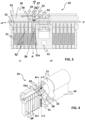
- the present invention overcomes the above-mentioned shortcomings by way of providing a special mechanical weakened notches along the cylinder lock (10) and the cylinder plug (30), said line being mechanically weakened to be ruptured in response to a breaking force applied by a suitable hand tool. Further, as a second security feature said retaining pin (32) retains the rest of the cylinder plug (30) in the cylinder lock (10) by blocking movement of the housing pin (52a).
- the cylinder lock (10) according to the present invention is arranged to have an increased safeguard against break-in attempts.
- said cylinder lock (10) comprising: a cylinder plug (30) having a keyway (35) adapted to receive a key; a longitudinally extending first cylinder half (23) and a second cylinder half (24); a rotatable cam (21) co-axial with and connected to the cylinder plug (30) for rotation therewith, the rotatable cam (21) being disposed externally of and between the first second cylinder halves (23, 24); a mechanically weakened cylinder notch (29) provided through at least part of the first cylinder half (23) for forming a breakable tip portion (28); a mechanically weakened plug notch (36) provided through at least part of the cylinder plug (30) for forming a breakable plug portion (22); a plurality of mutually aligned bores (54) extending at right-angles to the cylinder plug axis and in which housing pins (52) which are substantially of equal length and plug pins (53) which are of different lengths are biased in the direction of the keyway (35) under spring
- said cylinder lock (10) further comprises at least one retaining pin (32), pre-stressed and displaceable under a spring force, provided at the cylinder plug (30) and depressed by a retaining member (31), said retaining pin (32) adapted to match at least partly with a corresponding retaining recess (27) formed at the first cylinder half (23) such that when the mechanically weakened cylinder notch (29) and plug notch (36) breaks away, said retaining member (31) slides out of the first cylinder half (23) and said retaining pin (32) maintains rest of the cylinder plug (30) in the first cylinder half (23) by matching with the retaining recess (27).
- a tapped hole (41) can be provided in a direction transverse to the axis of rotation for securing the cylinder lock (10) in an aperture in a door.
- said cylinder lock (10) has two security options for break-in attempts in cylinder locks.
- One of the security features is that locking the cylinder plug (10) by triggering the retaining pin (32) and other security feature is that blocking the movement of the cylinder plug (10) in case of any removal of the retaining pin (32) in its seated retaining recess (27) by moving the retaining pin (32) to the slot (26) of the housing pin (52a).
- the retaining pin (32) works as a barrier mounted in a pin housing (37) for displacement in the first cylinder half (23) and being biased in the direction of the plug pins (53) by a thrust spring (33).
- one of the housing pins (52a) and one of the plug pins (53) are arranged in a same vertical axis (X) according to the longitudinal axis of the cylinder lock with the retaining pin (32).
- the housing pin (52a) has at least one slot (26) adapted to receive at least partly the retaining pin (32) such that said housing pin (52a) blocks movement of the cylinder plug (30) as a second security feature when the retaining pin (32) is removed from the recess (27) and the cylinder plug (30) is rotated.
- the cylinder plug (30) and the cylinder lock (10) are broken from their mechanically weakened notches such that said retaining pin (32) is triggered and pushed to the retaining recess (27) under the spring force from the thrust spring (33) located therein. Even it is removed from its retaining recess (27) still can be blocked by the slot (26) when the cylinder plug (30) is rotated axially.
- Said retaining pin (32) is configured to match with the slot (26) of the housing pin (52a) when the retaining pin (32) is removed from the retaining recess (27) and the cylinder plug (30) is rotated between 160° and 200°, more preferably 180, thus secured against rotation.
- the retaining member (31) can have a protrusion (34) arranged to fit in a groove (42) formed on the breakable plug portion of cylinder plug (30) such that when the cylinder plug (30) breaks away or is pulled, said retaining member (31) goes out with the breakable portion of the cylinder plug (30) by removing the pressure on the retaining pin (32).
- Said protrusion (34) can be formed as a sleeve which extends in the longitudinal axis (Y) of the cylinder lock (10).
- Said protrusion can have a shape of a semi dome which is shaped and dimensioned to fit the corresponding groove (42) further, it can be attached by using adhesive material thereof.
- a second cylinder half (24) can be used at the opposite side which defines a second bore having a second cylinder plug mounted therein, which is adapted to receive an external input and thereby be rotated within the second bore, and wherein the axis of rotation of the second cylinder plug is co-axial with the axis of rotation of the cylinder plug (30) and the rotatable cam (21), which the rotatable cam (21) is also connected to the second cylinder plug for rotation therewith.
- the rotatable cam (21) can also be configured to rotate with either the cylinder plug (30) or the second cylinder plug.
- said mechanically weakened cylinder notch (29) and the mechanically weakened plug notch (36) are arranged in a same vertical axis (X) according to the longitudinal axis (Y) of the cylinder lock with the retaining pin (32) such that both notches can be broken away at the same time.
- one end of the retaining recess (27) facing outside of the cylinder lock (10) can be closed for eliminating access to the retaining pin (32) after any break-in attempt.
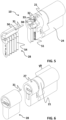
- FIG. 8 a cross sectional view of the retaining pin (32) and the housing pin (52a) having a slot corresponding slot (26) where the said parts are engaged with each other are shown.
- the retaining pin (32) is removed from the retaining recess (27) and the cylinder plug (30) is axially turned, the retaining pin (32), serving as a second security feature, is fastened at the slot (26) of the housing pin (52a) such that the rotation of the cylinder plug (30) is prevented.
- more than one retaining pins (32) and corresponding recesses (27) may be provided on the first cylinder half (23). It is evident that the retaining pin (23) is disposed sufficiently vertically in the cylinder lock (10) that the function of the housing pins (52) and of the plug pin (53) is not adversely affected.
- At least one hardened member (38, 39) can be used against drilling in the cylinder lock (10), especially, in the cylinder plug (30).
- a first hardened member (38) extending in a transverse direction of the cylinder lock (10).
- Said hardened members (38, 39) can be made of any chosen material, which may be different from the brass material from which the main part of the cylinder plug (30) is normally made.
- the hardened members (38, 39) may be made of stainless steel or hardened steel.
- the first hardened member (38) sits in an elongated recesses of the cylinder plug (30) and is, substantially, cylindrically formed.
- the second hardened member (39) sits in another elongated recesses of the cylinder plug (30) and is, substantially, cylindrically formed.
- Fig. 7 demonstrates a perspective view of the cylinder plug (30) for the cylinder lock (10) according another embodiment of the invention.
- a third hardened member (43) can be used against drilling as the first hardened member (38) used in the cylinder plug (30).
- Said third hardened member (43) can be formed as a semi-circle with a flat lower portion and an arc-shaped upper portion.
- Said third hardened member (43) is shaped and dimensioned to sit in a corresponding seat in the first cylinder half (23), which is also elastically loaded by at least one member spring (44).
- member spring (44) In a possible embodiment, two member springs (44) are located at the opposite ends of the flat lower portion of the third hardened member (43).
- Said third hardened member (43) is pre-stressed and displaceable under the spring force, and is depressed by the retaining member (31) as shown in fig. 10 .
- Said third hardened member (43) is adapted to match at least partly with a corresponding seat formed at the first cylinder half (23) such that when the mechanically weakened cylinder notch (29) and plug notch (36) breaks away, said retaining member (31) slides out of the first cylinder half (23) and said third hardened member (43) engage with the seat wherein reintroduction of the retaining member (31) is prevented.
Landscapes
- Engineering & Computer Science (AREA)
- Mechanical Engineering (AREA)
- Lock And Its Accessories (AREA)
Claims (15)
- - Serrure à cylindre (10) comprenant :un barillet de cylindre (30) ayant une entrée de clé (35) agencée pour recevoir une clé ;une première moitié de cylindre (23) s'étendant longitudinalement et une seconde moitié de cylindre (24) ;une came rotative (21) coaxiale et reliée au barillet de cylindre (30) pour tourner avec celui-ci, la came rotative (21) étant disposée à l'extérieur des première et secondes moitiés de cylindre (23, 24) et entre celles-ci ;une encoche de cylindre (29) mécaniquement affaiblie, ménagée à travers au moins une partie de la première moitié de cylindre (23) pour former une partie de pointe cassable (28) ;une encoche de barillet (36) mécaniquement affaiblie, ménagée à travers au moins une partie du barillet de cylindre (30) pour former une partie de barillet cassable (22) ;une pluralité d'alésages (54) mutuellement alignés, s'étendant perpendiculairement à l'axe de barillet de cylindre et dans lesquels des goupilles de boîtier (52) qui sont sensiblement de même longueur et des goupilles de barillet (53) qui sont de longueurs différentes sont sollicitées dans la direction de l'entrée de clé (35) sous l'action d'une force de ressort par une pluralité de ressorts (51) ; etau moins une goupille de retenue (32) qui est précontrainte et déplaçable sous l'action d'une force de ressort, la goupille de retenue (32) étant disposée au barillet de cylindre (30) dans sa position initiale normale et étant enfoncée par un élément de retenue (31), et ladite goupille de retenue (32) étant agencée pour être au moins partiellement mise en correspondance avec un évidement de retenue (27) correspondant formé à la première moitié de cylindre (23) de telle sorte que, lorsque l'encoche de cylindre (29) et l'encoche de barillet (36) mécaniquement affaiblies se détachent, ledit élément de retenue (31) coulisse hors de la première moitié de cylindre (23) et ladite goupille de retenue (32) maintient le reste du barillet de cylindre (30) dans la première moitié de cylindre (23) par mise en correspondance avec l'évidement de retenue (27).
- - Serrure à cylindre (10) selon la revendication 1, dans laquelle l'une des goupilles de boîtier (52a) et l'une des goupilles de barillet (53) sont disposées dans un même axe vertical (X), selon l'axe longitudinal de la serrure à cylindre, que la goupille de retenue (32).
- - Serrure à cylindre (10) selon la revendication 2, dans laquelle la goupille de boîtier (52a) a au moins une fente (26) agencée pour recevoir au moins partiellement la goupille de retenue (32) de telle sorte que ladite goupille de boîtier (52a) bloque un mouvement du barillet de cylindre (30) comme un second blocage lorsque la goupille de retenue (32) est retirée de l'évidement de retenue (27) et que le barillet de cylindre (30) est entraîné en rotation.
- - Serrure à cylindre (10) selon l'une quelconque des revendications précédentes, dans laquelle l'élément de retenue (31) a une saillie (34) agencée pour s'adapter dans une rainure (42) formée sur la partie de barillet cassable (22) du barillet de cylindre (30) de telle sorte que, lorsque le barillet de cylindre (30) se détache ou est tiré, ledit élément de retenue (31) sort avec le barillet de cylindre (30) en supprimant la pression exercée sur la goupille de retenue (32).
- - Serrure à cylindre (10) selon l'une quelconque des revendications précédentes, dans laquelle la seconde moitié de cylindre (24) définit un second alésage ayant un second barillet de cylindre monté dans celui-ci, qui est agencé pour recevoir une entrée externe et ainsi être entraîné en rotation dans le second alésage, et l'axe de rotation du second barillet de cylindre étant coaxial à l'axe de rotation du barillet de cylindre (30) et de la came rotative (21), laquelle came rotative (21) étant également reliée au second barillet de cylindre pour tourner avec celui-ci.
- - Serrure à cylindre (10) selon l'une quelconque des revendications précédentes, dans laquelle l'encoche de cylindre (29) mécaniquement affaiblie et l'encoche de barillet (36) mécaniquement affaiblie sont disposées dans un même axe vertical (X), selon l'axe longitudinal (Y) de la serrure à cylindre, que la goupille de retenue (32).
- - Serrure à cylindre (10) selon l'une quelconque des revendications précédentes, dans laquelle l'élément de retenue (31) se présente sous la forme d'un manchon qui s'étend selon l'axe longitudinal (Y) de la serrure à cylindre (10).
- - Serrure à cylindre (10) selon l'une quelconque des revendications précédentes, dans laquelle l'extrémité de l'évidement de retenue (27) donnant sur l'extérieur est fermée pour éliminer un accès à la goupille de retenue (32) après toute tentative d'effraction.
- - Serrure à cylindre (10) selon la revendication 5, dans laquelle la came rotative (21) est configurée pour tourner avec soit le barillet de cylindre (30) soit le second barillet de cylindre.
- - Serrure à cylindre (10) selon l'une quelconque des revendications précédentes, dans laquelle la goupille de retenue (32) est configurée pour être mise en correspondance avec la fente (26) de la goupille de boîtier (52a) lorsque la goupille de retenue (32) est retirée de l'évidement de retenue (27) et que le barillet de cylindre (30) est tourné entre 160° et 200°, de façon davantage préférée de 180°.
- - Serrure à cylindre (10) selon l'une quelconque des revendications précédentes, la serrure à cylindre (10) comprenant en outre au moins un élément durci (38, 39, 43) fait d'un matériau plus dur que le matériau du barillet de cylindre (30).
- - Serrure à cylindre (10) selon la revendication 11, dans laquelle les premier, deuxième et troisième éléments durcis (38, 39, 43) sont placés dans une direction qui est perpendiculaire à l'axe longitudinal de la serrure à cylindre (10).
- - Serrure à cylindre (10) selon la revendication 12, dans laquelle le troisième élément durci (43) est sollicité par ressort avec au moins un ressort d'élément (44) et enfoncé par l'élément de retenue (31) de telle sorte que, lorsque l'encoche de cylindre (29) et l'encoche de barillet (36) mécaniquement affaiblies se détachent, ledit élément de retenue (31) coulisse hors de la première moitié de cylindre (23) par une pression de levage sur le troisième élément durci (43), ledit troisième élément durci (43) s'engageant avec un siège en empêchant une réintroduction de l'élément de retenue (31).
- - Serrure à cylindre (10) selon la revendication 13, dans laquelle le troisième élément durci (43) se présente sensiblement sous la forme d'un demi-cercle avec une partie inférieure plate et une partie supérieure en forme d'arc.
- - Porte comportant une serrure à cylindre (10) selon l'une quelconque des revendications précédentes.
Applications Claiming Priority (1)
| Application Number | Priority Date | Filing Date | Title |
|---|---|---|---|
| PCT/TR2018/050272 WO2019231411A1 (fr) | 2018-05-28 | 2018-05-28 | Serrure à barillet à sécurité renforcée contre les tentatives d'effraction |
Publications (4)
| Publication Number | Publication Date |
|---|---|
| EP3802997A1 EP3802997A1 (fr) | 2021-04-14 |
| EP3802997A4 EP3802997A4 (fr) | 2021-06-23 |
| EP3802997C0 EP3802997C0 (fr) | 2024-12-18 |
| EP3802997B1 true EP3802997B1 (fr) | 2024-12-18 |
Family
ID=68698915
Family Applications (1)
| Application Number | Title | Priority Date | Filing Date |
|---|---|---|---|
| EP18921076.8A Active EP3802997B1 (fr) | 2018-05-28 | 2018-05-28 | Serrure à barillet à sécurité renforcée contre les tentatives d'effraction |
Country Status (3)
| Country | Link |
|---|---|
| EP (1) | EP3802997B1 (fr) |
| ES (1) | ES3010060T3 (fr) |
| WO (1) | WO2019231411A1 (fr) |
Family Cites Families (6)
| Publication number | Priority date | Publication date | Assignee | Title |
|---|---|---|---|---|
| GB2318824B (en) * | 1996-11-02 | 2001-01-31 | Anglian Windows Ltd | Euro-cylinder door locks |
| DE20021352U1 (de) | 2000-12-16 | 2001-03-22 | Aug. Winkhaus GmbH & Co. KG., 48291 Telgte | Schließzylinder |
| WO2004070143A1 (fr) * | 2003-02-10 | 2004-08-19 | Kolektor Group Vodenje In Upravljanje Druzb D.O.O. | Barillet de serrure à clé |
| ATE472653T1 (de) * | 2005-03-30 | 2010-07-15 | Wfe Technology Corp | Zylinderschlosseinheit mit mechanischem und elektronischem mechanismus |
| GB2461297A (en) * | 2008-06-26 | 2009-12-30 | Avocet Hardware Ltd | Lock with additional security mechanism and clutch |
| AT513607B1 (de) * | 2012-11-08 | 2014-06-15 | Evva Sicherheitstechnologie | Zylinderschloss |
-
2018
- 2018-05-28 ES ES18921076T patent/ES3010060T3/es active Active
- 2018-05-28 EP EP18921076.8A patent/EP3802997B1/fr active Active
- 2018-05-28 WO PCT/TR2018/050272 patent/WO2019231411A1/fr not_active Ceased
Also Published As
| Publication number | Publication date |
|---|---|
| ES3010060T3 (en) | 2025-04-01 |
| EP3802997A4 (fr) | 2021-06-23 |
| WO2019231411A1 (fr) | 2019-12-05 |
| EP3802997A1 (fr) | 2021-04-14 |
| EP3802997C0 (fr) | 2024-12-18 |
Similar Documents
| Publication | Publication Date | Title |
|---|---|---|
| EP2292879B1 (fr) | Dispositif de verrouillage et clé | |
| US6910356B2 (en) | Anti-pick mogul cylinder | |
| US4282731A (en) | Pin-tumbler-type lock having antipick security action | |
| US4008588A (en) | Rotary plug cylinder lock construction | |
| US6883355B2 (en) | High security combination padlock with locking bar | |
| US4961328A (en) | Lock bit arresting cylinder lock | |
| EP2992152B1 (fr) | Serrure à cylindre présentant fonction anti-rupture | |
| EP2262964B1 (fr) | Serrure a barillet | |
| US3234768A (en) | Key actuated mechanism with temporary ball tumbler | |
| US4576025A (en) | Magnetic lock insert for lock mechanisms | |
| US4300374A (en) | Key retaining cylinder for a lock | |
| GB2545389A (en) | Security mechanism | |
| EP3802997B1 (fr) | Serrure à barillet à sécurité renforcée contre les tentatives d'effraction | |
| US6948345B1 (en) | Lock enhancement arrangement | |
| EP3222799B1 (fr) | Serrure cylindrique | |
| US3172284A (en) | Construction lock cylinder | |
| US3448599A (en) | Key-operated lock mounting and removing arrangement | |
| PL181906B1 (pl) | Bebenek zamykajacy i sposób wytwarzania bebenka zamykajacego PL | |
| US4580425A (en) | High security lock | |
| DE4310107C1 (de) | Schließzylinder | |
| EP2894279A1 (fr) | Dispositif de sécurité pour cylindres de serrure | |
| RU2170315C1 (ru) | Замок | |
| EP3150783B1 (fr) | Rotor pour une serrure | |
| EP3227514B1 (fr) | Système de verrouillage de sécurité | |
| JPH01299968A (ja) | サイドバーロック装置 |
Legal Events
| Date | Code | Title | Description |
|---|---|---|---|
| STAA | Information on the status of an ep patent application or granted ep patent |
Free format text: STATUS: THE INTERNATIONAL PUBLICATION HAS BEEN MADE |
|
| PUAI | Public reference made under article 153(3) epc to a published international application that has entered the european phase |
Free format text: ORIGINAL CODE: 0009012 |
|
| STAA | Information on the status of an ep patent application or granted ep patent |
Free format text: STATUS: REQUEST FOR EXAMINATION WAS MADE |
|
| 17P | Request for examination filed |
Effective date: 20201223 |
|
| AK | Designated contracting states |
Kind code of ref document: A1 Designated state(s): AL AT BE BG CH CY CZ DE DK EE ES FI FR GB GR HR HU IE IS IT LI LT LU LV MC MK MT NL NO PL PT RO RS SE SI SK SM TR |
|
| AX | Request for extension of the european patent |
Extension state: BA ME |
|
| A4 | Supplementary search report drawn up and despatched |
Effective date: 20210527 |
|
| RIC1 | Information provided on ipc code assigned before grant |
Ipc: E05B 9/04 20060101AFI20210520BHEP Ipc: E05B 17/20 20060101ALI20210520BHEP Ipc: E05B 27/00 20060101ALI20210520BHEP Ipc: E05B 15/16 20060101ALN20210520BHEP |
|
| DAV | Request for validation of the european patent (deleted) | ||
| DAX | Request for extension of the european patent (deleted) | ||
| STAA | Information on the status of an ep patent application or granted ep patent |
Free format text: STATUS: EXAMINATION IS IN PROGRESS |
|
| 17Q | First examination report despatched |
Effective date: 20220411 |
|
| GRAP | Despatch of communication of intention to grant a patent |
Free format text: ORIGINAL CODE: EPIDOSNIGR1 |
|
| STAA | Information on the status of an ep patent application or granted ep patent |
Free format text: STATUS: GRANT OF PATENT IS INTENDED |
|
| RIC1 | Information provided on ipc code assigned before grant |
Ipc: E05B 15/16 20060101ALN20240726BHEP Ipc: E05B 27/00 20060101ALI20240726BHEP Ipc: E05B 17/20 20060101ALI20240726BHEP Ipc: E05B 9/04 20060101AFI20240726BHEP |
|
| INTG | Intention to grant announced |
Effective date: 20240826 |
|
| GRAS | Grant fee paid |
Free format text: ORIGINAL CODE: EPIDOSNIGR3 |
|
| GRAA | (expected) grant |
Free format text: ORIGINAL CODE: 0009210 |
|
| STAA | Information on the status of an ep patent application or granted ep patent |
Free format text: STATUS: THE PATENT HAS BEEN GRANTED |
|
| AK | Designated contracting states |
Kind code of ref document: B1 Designated state(s): AL AT BE BG CH CY CZ DE DK EE ES FI FR GB GR HR HU IE IS IT LI LT LU LV MC MK MT NL NO PL PT RO RS SE SI SK SM TR |
|
| REG | Reference to a national code |
Ref country code: CH Ref legal event code: EP |
|
| REG | Reference to a national code |
Ref country code: DE Ref legal event code: R096 Ref document number: 602018077836 Country of ref document: DE |
|
| REG | Reference to a national code |
Ref country code: IE Ref legal event code: FG4D |
|
| U01 | Request for unitary effect filed |
Effective date: 20250116 |
|
| RAP4 | Party data changed (patent owner data changed or rights of a patent transferred) |
Owner name: KALE KILIT VE KALIP SANAYI ANONIM SIRKETI |
|
| U07 | Unitary effect registered |
Designated state(s): AT BE BG DE DK EE FI FR IT LT LU LV MT NL PT RO SE SI Effective date: 20250131 |
|
| REG | Reference to a national code |
Ref country code: ES Ref legal event code: FG2A Ref document number: 3010060 Country of ref document: ES Kind code of ref document: T3 Effective date: 20250401 |
|
| PG25 | Lapsed in a contracting state [announced via postgrant information from national office to epo] |
Ref country code: HR Free format text: LAPSE BECAUSE OF FAILURE TO SUBMIT A TRANSLATION OF THE DESCRIPTION OR TO PAY THE FEE WITHIN THE PRESCRIBED TIME-LIMIT Effective date: 20241218 |
|
| PG25 | Lapsed in a contracting state [announced via postgrant information from national office to epo] |
Ref country code: NO Free format text: LAPSE BECAUSE OF FAILURE TO SUBMIT A TRANSLATION OF THE DESCRIPTION OR TO PAY THE FEE WITHIN THE PRESCRIBED TIME-LIMIT Effective date: 20250318 |
|
| PG25 | Lapsed in a contracting state [announced via postgrant information from national office to epo] |
Ref country code: GR Free format text: LAPSE BECAUSE OF FAILURE TO SUBMIT A TRANSLATION OF THE DESCRIPTION OR TO PAY THE FEE WITHIN THE PRESCRIBED TIME-LIMIT Effective date: 20250319 |
|
| PG25 | Lapsed in a contracting state [announced via postgrant information from national office to epo] |
Ref country code: RS Free format text: LAPSE BECAUSE OF FAILURE TO SUBMIT A TRANSLATION OF THE DESCRIPTION OR TO PAY THE FEE WITHIN THE PRESCRIBED TIME-LIMIT Effective date: 20250318 |
|
| PGFP | Annual fee paid to national office [announced via postgrant information from national office to epo] |
Ref country code: TR Payment date: 20250318 Year of fee payment: 8 |
|
| U20 | Renewal fee for the european patent with unitary effect paid |
Year of fee payment: 8 Effective date: 20250507 |
|
| PG25 | Lapsed in a contracting state [announced via postgrant information from national office to epo] |
Ref country code: SM Free format text: LAPSE BECAUSE OF FAILURE TO SUBMIT A TRANSLATION OF THE DESCRIPTION OR TO PAY THE FEE WITHIN THE PRESCRIBED TIME-LIMIT Effective date: 20241218 |
|
| PG25 | Lapsed in a contracting state [announced via postgrant information from national office to epo] |
Ref country code: PL Free format text: LAPSE BECAUSE OF FAILURE TO SUBMIT A TRANSLATION OF THE DESCRIPTION OR TO PAY THE FEE WITHIN THE PRESCRIBED TIME-LIMIT Effective date: 20241218 |
|
| PGFP | Annual fee paid to national office [announced via postgrant information from national office to epo] |
Ref country code: GB Payment date: 20250422 Year of fee payment: 8 Ref country code: ES Payment date: 20250604 Year of fee payment: 8 |
|
| PG25 | Lapsed in a contracting state [announced via postgrant information from national office to epo] |
Ref country code: IS Free format text: LAPSE BECAUSE OF FAILURE TO SUBMIT A TRANSLATION OF THE DESCRIPTION OR TO PAY THE FEE WITHIN THE PRESCRIBED TIME-LIMIT Effective date: 20250418 |
|
| PG25 | Lapsed in a contracting state [announced via postgrant information from national office to epo] |
Ref country code: SK Free format text: LAPSE BECAUSE OF FAILURE TO SUBMIT A TRANSLATION OF THE DESCRIPTION OR TO PAY THE FEE WITHIN THE PRESCRIBED TIME-LIMIT Effective date: 20241218 |
|
| PG25 | Lapsed in a contracting state [announced via postgrant information from national office to epo] |
Ref country code: CZ Free format text: LAPSE BECAUSE OF FAILURE TO SUBMIT A TRANSLATION OF THE DESCRIPTION OR TO PAY THE FEE WITHIN THE PRESCRIBED TIME-LIMIT Effective date: 20241218 |
|
| PLBE | No opposition filed within time limit |
Free format text: ORIGINAL CODE: 0009261 |
|
| STAA | Information on the status of an ep patent application or granted ep patent |
Free format text: STATUS: NO OPPOSITION FILED WITHIN TIME LIMIT |
|
| REG | Reference to a national code |
Ref country code: CH Ref legal event code: L10 Free format text: ST27 STATUS EVENT CODE: U-0-0-L10-L00 (AS PROVIDED BY THE NATIONAL OFFICE) Effective date: 20251029 |
|
| 26N | No opposition filed |
Effective date: 20250919 |
|
| REG | Reference to a national code |
Ref country code: CH Ref legal event code: H13 Free format text: ST27 STATUS EVENT CODE: U-0-0-H10-H13 (AS PROVIDED BY THE NATIONAL OFFICE) Effective date: 20251223 |
|
| PG25 | Lapsed in a contracting state [announced via postgrant information from national office to epo] |
Ref country code: CH Free format text: LAPSE BECAUSE OF NON-PAYMENT OF DUE FEES Effective date: 20250531 |
|
| PG25 | Lapsed in a contracting state [announced via postgrant information from national office to epo] |
Ref country code: MC Free format text: LAPSE BECAUSE OF FAILURE TO SUBMIT A TRANSLATION OF THE DESCRIPTION OR TO PAY THE FEE WITHIN THE PRESCRIBED TIME-LIMIT Effective date: 20241218 |
|
| PG25 | Lapsed in a contracting state [announced via postgrant information from national office to epo] |
Ref country code: IE Free format text: LAPSE BECAUSE OF NON-PAYMENT OF DUE FEES Effective date: 20250528 |