EP3803042B1 - Détermination de densité de boue de forage sûre - Google Patents
Détermination de densité de boue de forage sûre Download PDFInfo
- Publication number
- EP3803042B1 EP3803042B1 EP19731095.6A EP19731095A EP3803042B1 EP 3803042 B1 EP3803042 B1 EP 3803042B1 EP 19731095 A EP19731095 A EP 19731095A EP 3803042 B1 EP3803042 B1 EP 3803042B1
- Authority
- EP
- European Patent Office
- Prior art keywords
- computer
- values
- average
- mud weight
- wellbore
- Prior art date
- Legal status (The legal status is an assumption and is not a legal conclusion. Google has not performed a legal analysis and makes no representation as to the accuracy of the status listed.)
- Active
Links
Images


Classifications
-
- E—FIXED CONSTRUCTIONS
- E21—EARTH OR ROCK DRILLING; MINING
- E21B—EARTH OR ROCK DRILLING; OBTAINING OIL, GAS, WATER, SOLUBLE OR MELTABLE MATERIALS OR A SLURRY OF MINERALS FROM WELLS
- E21B49/00—Testing the nature of borehole walls; Formation testing; Methods or apparatus for obtaining samples of soil or well fluids, specially adapted to earth drilling or wells
-
- E—FIXED CONSTRUCTIONS
- E21—EARTH OR ROCK DRILLING; MINING
- E21B—EARTH OR ROCK DRILLING; OBTAINING OIL, GAS, WATER, SOLUBLE OR MELTABLE MATERIALS OR A SLURRY OF MINERALS FROM WELLS
- E21B47/00—Survey of boreholes or wells
- E21B47/007—Measuring stresses in a pipe string or casing
-
- E—FIXED CONSTRUCTIONS
- E21—EARTH OR ROCK DRILLING; MINING
- E21B—EARTH OR ROCK DRILLING; OBTAINING OIL, GAS, WATER, SOLUBLE OR MELTABLE MATERIALS OR A SLURRY OF MINERALS FROM WELLS
- E21B47/00—Survey of boreholes or wells
- E21B47/06—Measuring temperature or pressure
-
- E—FIXED CONSTRUCTIONS
- E21—EARTH OR ROCK DRILLING; MINING
- E21B—EARTH OR ROCK DRILLING; OBTAINING OIL, GAS, WATER, SOLUBLE OR MELTABLE MATERIALS OR A SLURRY OF MINERALS FROM WELLS
- E21B47/00—Survey of boreholes or wells
- E21B47/26—Storing data down-hole, e.g. in a memory or on a record carrier
-
- E—FIXED CONSTRUCTIONS
- E21—EARTH OR ROCK DRILLING; MINING
- E21B—EARTH OR ROCK DRILLING; OBTAINING OIL, GAS, WATER, SOLUBLE OR MELTABLE MATERIALS OR A SLURRY OF MINERALS FROM WELLS
- E21B49/00—Testing the nature of borehole walls; Formation testing; Methods or apparatus for obtaining samples of soil or well fluids, specially adapted to earth drilling or wells
- E21B49/005—Testing the nature of borehole walls or the formation by using drilling mud or cutting data
-
- G—PHYSICS
- G01—MEASURING; TESTING
- G01V—GEOPHYSICS; GRAVITATIONAL MEASUREMENTS; DETECTING MASSES OR OBJECTS; TAGS
- G01V1/00—Seismology; Seismic or acoustic prospecting or detecting
- G01V1/40—Seismology; Seismic or acoustic prospecting or detecting specially adapted for well-logging
- G01V1/44—Seismology; Seismic or acoustic prospecting or detecting specially adapted for well-logging using generators and receivers in the same well
- G01V1/48—Processing data
- G01V1/50—Analysing data
-
- G—PHYSICS
- G01—MEASURING; TESTING
- G01V—GEOPHYSICS; GRAVITATIONAL MEASUREMENTS; DETECTING MASSES OR OBJECTS; TAGS
- G01V2210/00—Details of seismic processing or analysis
- G01V2210/60—Analysis
- G01V2210/64—Geostructures, e.g. in 3D data cubes
- G01V2210/646—Fractures
Definitions
- the present disclosure relates to determining wellbore stability and, in particular, determining a safe drilling mud weight.
- Determining the mud weight is important to many practical applications related to wellbore stability analysis for safe drilling practice. Certain geo-mechanical and petrophysical properties of naturally fractured rocks may inform a geologist, engineer, or driller about the safe drilling mud weight window for a particular wellbore. Natural fractures' properties, such as their dimension, distribution, and density, play essential roles in altering the bulk rocks' strength and mechanical properties and are crucial factors for the determination of safe drilling mud weight.
- WO 2013/112114 describes a computer-implemented method of modeling a formation in 3-D and determining a plurality of effective stress ratios for the modeled 3-D formation using finite element analysis. Thereafter, the trajectory of a proposed wellbore through the 3-D modeled formation is plotted and the specific effective stress ratios along the wellbore are selected to form a data set. The 3-D data set of effective stress ratios is then imported into 1-D modeling software and combined with 1-D data. The combined data is thereafter utilized to estimate the mud weigh window for the formation around the wellbore.
- the invention relates to a computer-implemented method as specified in claim 1, to a non-transitory computer-readable medium as specified in claim 11 and to a computer-implemented system as specified in claim 12. .
- Implementations of the claimed subject matter are generally directed to determining a safe drilling mud weight of a wellbore based on a dual-porosity dual-permeability poroelastic model.
- a naturally fractured rock is simulated as an overlapping of two porous media each of which has its own properties.
- Geomechanical properties, such as compressibility, as well as the distribution and the size of the naturally fractured rock are taken into account when using the model to make such determinations.
- a number of average compressibility values of a fractured rock in a wellbore from a depth of interest is determined, where each of the number of average compressibility values is determined according to a different average scheme. For each of the number average compressibility values, a set of effective stresses' values based on that average compressibility value are determined. For each determined set of stresses values, a set of mud weight window values are determined based on the set of stresses values. A mud weight for the wellbore is adjusted to be within the determined set of mud weight window.
- Implementations of the described subject matter can be implemented using a computer-implemented method; a non-transitory, computer-readable medium storing computer-readable instructions to perform the computer-implemented method; and a computer-implemented system including one or more computer memory devices interoperably coupled with one or more computers and having tangible, non-transitory, machine-readable media storing instructions that, when executed by the one or more computers, perform the computer-implemented method/the computer-readable instructions stored on the non-transitory, computer-readable medium.
- the bulk compressibility of fractured rocks can be calculated from logs with the fractures' geometry.
- the range of the safe drilling mud weight window can also be calculated based on fractures' geometry, as shown in Figs. 3A -3B .
- the proposed model quantifies the effects of natural fractures on wellbore instability, enhancing the understanding of wellbore stability in naturally fractured formations and helping to design safe mud weight to improve the wellbore stability.
- the present disclosure describes developing a dual-porosity dual-permeability poroelastic model to determine a safe drilling mud weight window of a wellbore, and is presented to enable any person skilled in the art to make and use the disclosed subject matter in the context of one or more particular implementations.
- Various modifications, alterations, and permutations of the disclosed implementations can be made and will be readily apparent to those of ordinary skill in the art, and the general principles defined can be applied to other implementations and applications, without departing from the scope of the present disclosure.
- one or more technical details that are unnecessary to obtain an understanding of the described subject matter and that are within the skill of one of ordinary skill in the art may be omitted so as to not obscure one or more described implementations.
- the present disclosure is not intended to be limited to the described or illustrated implementations, but to be accorded the widest scope consistent with the described principles and features.
- Wellbore instability problems in naturally fractured shale formations have been widely recorded in the oil and gas drilling practice. Such problems include fluid loss circulation, wellbore collapse, wellbore enlargement, tight holes, and washouts. The cost of drilling non-productive time associated with these wellbore instability problems is estimated to be around several billions of dollars per year.
- Field drilling operations have shown that drilling mud weight is a crucial factor controlling wellbore stability in naturally fractured formations.
- the dual-porosity dual-permeability poroelastic model has been used to theoretically show that natural fractures are detrimental to wellbore stability and that the safe drilling mud weight window for naturally fractured rock formation is narrower than that of intact rock with the same rock type.
- wellbore image logs have shown various size and distribution of natural fractures in the subsurface formations.
- Formation's compressibility is an essential factor controlling fluid diffusivity, formation's deformation, and the stress fields around the wellbore.
- wellbore stability is influenced by the formation's compressibility as well. While the properties of naturally fractured rocks can influence the safe drilling mud weight, the geometrical features of naturally fractured rocks can also control the safe mud drilling weight.
- a geomechanics simulator is developed to quantitatively show the effects of the fractures' geometry on the time-dependent safe mud weight.
- a naturally fractured rock is simulated as consisting of two separate and overlapping porous media: one represents the primary porosity (matrix) and the other represents the secondary porosity medium (fracture).
- matrix porosity
- fracture porosity medium
- Each medium is assigned poromechanical and petrophysical properties.
- the dual-porosity dual-permeability poroelastic model for an inclined wellbore drilled through a naturally fractured rock formation and subjected to three-dimensional state of stress has been implemented in a stability analyzer.
- the average properties of the naturally fractured rock are determined based on at least one of the fractures' size, density, or distribution.
- the dual-porosity dual-permeability poroelastic model updates the wellbore stresses, pore pressure, mud weight window, and failure regions.
- the selection of the appropriate average scheme depends on the fractures' geometrical characteristics that can be obtained by image logs.
- the modeling result shows that the time-dependent stresses, pore pressure, and safe drilling mud weight window vary significantly with the average schemes
- Equations (1)-(3) the superscripts I and II refer to the porous rock matrix and the porous fracture medium, respectively, ⁇ ij and ⁇ ij are the components of the stress and strain tensors, respectively, C and v are the average compressibility and Poisson's ratio, respectively, ⁇ ij is the Kronecker Delta, ⁇ -I and ⁇ -I are the effective pore pressure coefficients, p I and p II are the matrix and fracture pore pressure, respectively, ⁇ is the volumetric strain, ⁇ I and ⁇ II are the variation of total fluid contents, M I , M II , and M I,II are the effective coupled Biot moduli.
- Equations (4) and (5) q i I and q i II are the flow velocities in the x i -direction in matrix and fractures, respectively, k I and k II are the matrix and fracture permeability, respectively, and ⁇ is the fluid viscosity.
- v I and v II are the bulk volume fractions
- ⁇ is the inter-porosity flow coefficient
- the average compressibility C plays an important role in the stress-strain relations.
- three average schemes that is, harmonic mean, geometric mean, and arithmetic mean, are introduced to calculate this average compressibility from the individual compressibility of rock matrix and fractures.
- Table 1 illustrates differences in the results calculated by these three average schemes. As illustrated by Table 1, among these three results, an increase of the value of the individual compressibility contributes more significantly to the arithmetic mean, and less significantly to the geometric mean and the harmonic mean. Table 1. Illustration of the differences among the three average schemes.
- the effective stress fields around the wellbore can be calculated using the dual-porosity dual-permeability poroelastic model.
- Three effective stresses ( ⁇ ' rr , ⁇ ' ⁇ , ⁇ ' zz ) and three shear stresses ( ⁇ r ⁇ , ⁇ ⁇ z , ⁇ rz ) are determined based on the average compressibility value.
- ⁇ ' rr , ⁇ ' ⁇ , ⁇ ' zz are the effective radial, tangential, and axial stresses around the wellbore, respectively
- ⁇ r ⁇ , ⁇ ⁇ z , ⁇ rz are the shear stresses in the planes of r- ⁇ , ⁇ -z, and r-z, respectively.
- the calculated stresses are combined with a shear failure criterion and tensile strength to determine the mud weight window.
- the Drucker-Prager criterion is applied to analyze wellbore collapse and shear failure.
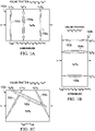
- FIGS. 1A-1C represent an example set of average permeability values associated with fractured rocks (100a, 100b and 100c) calculated by different average schemes.
- the effective macroscopic conductivity of a heterogeneous medium depends not only on the statistical distribution of the local conductivities, but also on the geometrical and topological manner in which the local conductivity is distributed.
- upper and lower bounds can be computed for the overall effective conductivity. The lower bound is often called the harmonic mean, whereas the upper bound is called the arithmetic mean.
- FIG. 1A (the lower bound of the calculated average permeability value) illustrates an extreme case that corresponds to a series arrangement of the conductive elements 102a, 104a, and 106a
- FIG. 1B (the upper bound of the calculated average permeability value) illustrates another extreme case in which all of the conductive elements 102b, 104b, and 106b are arranged in parallel with each other.
- the imposed pressure gradient is in the x-axis direction.
- the average permeability k HM is controlled by the rock matrix permeability K m , and the rock fracture permeability k f 1 , k f 2 and k f 3 have insignificant contribution to the average permeability.
- the rock fracture permeability k f 1, k f 2 and k f 3 significantly contribute to the average permeability k AM .
- the average permeabilityk can also be calculated by other types of average schemes (for example, as illustrated in FIG. 1C ), but the results should be in the range of the average permeability value calculated by the harmonic average and arithmetic average.
- FIGS. 2A-2B represent an example set of graphs illustrating fractured rock samples 200a and 200b with different fracture distributions and fracture sizes.
- the fractures of the fractured rock sample 200a illustrated in FIG. 2A are almost evenly distributed with fractures (represented by fracture 202a) having similar size, while the fractures of the fractured rock sample 200b illustrated in FIG. 2B are more or less evenly distributed fractures (represented by fracture 202b) with some fractures (represented by fracture 204b) having a significantly larger size comparing to fracture 202b.
- FIGS. 3A-3B represent an example set of graphs illustrating the results to a numerical example which is studied to investigate the effect of rock average compressibility on the evolution of wellbore effective stress fields and mud weight window during drilling through a naturally fractured rock formation.
- effective tangential stress is used as an example to show the effect of different average schemes on the wellbore effective stress fields.
- the dual-porosity rock formation is under in-situ stresses and pore pressures are assumed to be in balance.
- the wellbore is filled with a drilling fluid and there is a constant-thickness mudcake buildup on the wellbore wall, causing additional stresses around the wellbore.
- These coupled effects lead to time-dependent poromechanical responses such as redistribution of stresses and pore pressures in and around the wellbore, thus affecting the overall wellbore stability.
- the in-situ stresses, the pore pressure, and the wellbore information of the wellbore used in this example, are presented in Table 4.
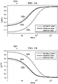
- FIGS. 3A-3B represent an example set of charts 300a and 300b illustrating the effective tangential stress values on the wellbore wall calculated in the direction of the minimal principal in-plane stress ( S min ) and the maximum principal in-plane stress ( S max ).
- Drilling process alters the states of in-situ principal stresses of the formation, that is, vertical stress ( S v ), and the maximum and minimum horizontal stresses ( S max and S min ) around the field of the wellbore. Drilling-induced stresses are introduced around the wellbore wall whose magnitudes will revert to the in-situ stresses as moving away from the wellbore wall.
- the tangential stresses are functions of the pressure p w . Therefore, any change in the mud pressure will influence the tangential stress ⁇ ⁇ .
- ⁇ ij ' is the effective stress.
- Three types of effective stresses can be calculated by Equation (13): effective tangential stress ( ⁇ ' ⁇ ), effective axial stress ( ⁇ ' rr ), and effective radial stress ( ⁇ ' zz ).
- the value of the effective stress is dependent on the average compressibility and is time-dependent.
- line 302a represents the result of the effective tangential stress in the direction of S min for the case of harmonic mean
- line 304a represents the result of the effective tangential stress in the direction of S min for the case of geometric mean
- line 306a represents the result of the effective tangential stress in the direction of S min for the case of arithmetic mean.
- the result shows by line 302a is always greater than line 306a, where the result shown by line 304a is in between. Therefore, it is concluded that the effective tangential stress in the direction of S min is the largest for the case of harmonic mean and the smallest for the case of arithmetic mean.
- line 302b represents the result of the effective tangential stress in the direction of S max for the case of harmonic mean
- line 304b represents the result of the effective tangential stress in the direction of S max for the case of geometric mean
- line 306b represents the result of the effective tangential stress in the direction of S max for the case of mean arithmetic mean.
- the result shows by line 306b is greater than line 302b, where the result shown by line 304b is in between. Therefore, it is concluded that the effective tangential stress in the direction of S max is the lowest for the case of harmonic mean and the largest for the case of arithmetic mean.
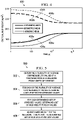
- FIG. 4 represents an example chart 400 illustrating the different prediction results of the mud weight window among the three average schemes.
- FIG. 4 demonstrates significant difference among the mud weight window corresponding to different average schemes.
- wellbore collapse is caused by excessive effective compressive stress concentration at or near the borehole wall where the drilling mud lacks the density and chemistry balance that can prevent rock failure.
- fracturing is created by excessive effective tensile stress concentration due to high mud density and chemical osmotic influx.
- a greater mud density can generate a tensile hoop stress that is closer to the minimum horizontal stress.
- Reduction of mud pressure, corresponding to lower confining pressure increases the potential for shear failure.
- increasing the mud pressure above a certain limit causes the tensile failure to happen.
- a stable window for the mud weight exists to drill the wellbore for a stable condition.
- the lower limit for this window corresponds to the shear failure (breakouts) pressure, while the upper limit corresponds to the fracture initiation pressure. Therefore, two types of failures are usually considered when analyzing a wellbore failure: the tensile failure and the shear failure.
- the shear failure known as breakout, can, in some implementations, happen at the point of maximum tangential stress where the rock is under maximum compression.
- the tensile failure known as hydraulic or induced fracture, however, is expected to occur at the point where minimum tangential stress is applied to the rock, 90° away from the location of shear failure around the wellbore.
- the harmonic mean should be used to predict the lowest fracturing mud weight.
- the effective tangential stress in the direction of S min is the largest for the case of the harmonic mean, and the point on the wellbore wall in the direction of S min has greater potential of collapse than other points, among the three average schemes, the harmonic mean should be used to predict the highest collapse mud weight.
- the failure potential manifested by the above redistributed effective stress field is illustrated in terms of the mud weight windows which are the safe ranges of drilling mud density to avoid both formation collapse and fracturing, as shown in FIG. 4 .
- a rock failure criterion can be applied to analyze wellbore collapse and shear failure.
- the narrowest mud weight window ranges from less than 1000 kg/m 3 to around 2200 kg/m 3
- the broadest mud weight window ranges from less than 450 kg/m 3 to around 2350 kg/m 3.
- the narrowest mud weight window (between line 402a and 402b), which has the highest lower limit and the lowest upper limit, corresponds to the harmonic mean.
- the broadest mud weight window (between line 406a and 406b), which has the lowest lower limit and the highest upper limit, corresponds to the arithmetic mean. Therefore, in this example, among the mud weight window calculated by the three average schemes, the mud weight window calculated by the harmonic mean should be used to adjust the mud weight.
- FIG. 5 represents an example flowchart 500 for determining a safe drilling mud weight using the proposed dual-porosity dual-permeability poroelastic model.
- the model used in the method 500 in the present disclosure also takes into account the geomechanical and petrophysical properties of naturally fractured rock samples.
- the description that follows generally describes method 500 in the context of the numerical example as illustrated in FIGS. 3A-4 .
- method 500 can be performed, for example, by any system, environment, software, and hardware, or a combination of systems, environments, software, and hardware, as appropriate.
- various steps of method 500 can be run in parallel, in combination, in loops, or in any order.
- a number of average compressibility values of a fractured rock in a wellbore from a depth of interest is determined, where each of the number of average compressibility values is determined according to a different average scheme.
- the average compressibility of a naturally fractured rock formation plays an important role in the stress-strain relations. In some implementations, however, properties other than the average compressibility may also be calculated in this step. Further, because the average compressibility of the naturally fractured rock are determined based on the fractures' size, density, and distribution, in some implementations, at least three average schemes have been implemented, that is, harmonic mean, geometric mean, and arithmetic mean, to determine the average compressibility. The values of the determined average compressibility according to different average schemes is dependent on the fractures' geometrical characteristics, as discussed in conjunction with FIGS. 1A-1C and 2A-2B . From 502, method 500 proceeds to 504.
- determining a set of stresses values includes determining values of the effective tangential stress ( ⁇ ' rr ), the effective axial stress ( ⁇ ' ⁇ ), the effective radial stress ( ⁇ ' zz ) and the three shear stresses ( ⁇ r ⁇ , ⁇ ⁇ z , ⁇ rz , respectively).
- the values of the three effective stresses and the three shear stresses can be obtained by known methods in existing technology.
- determining the set of effective stresses' values includes substituting each of the number of average compressibility value together with at least one of a wellbore trajectory, an in-situ stresses, a pore pressure, and a rock poromechanical properties to a dual-porosity poroelastic analytic solution.
- a set of mud weight window values is determined based on the determined set of stresses values.
- the determined stresses values are combined with a shear failure criterion and tensile strength to determine the mud weight window.
- the Drucker-Prager failure criterion can be applied in this step.
- the set of mud weight window values with the smallest range of values is selected.
- the mud weight window with the highest lower limit and the lowest upper limit, corresponding to the highest collapse mud weight and the lowest fracturing mud weight can be selected as the safe drilling mud weight window.
- the lower limit and the upper limit of the mud weight window also correspond to the lowest effective tangential stress and the largest effective tangential stress, respectively, where each of the lowest and the largest effective tangential stresses can be calculated by one of the average schemes as provided. From 505, method 500 proceeds to 508.
- the mud weight for the wellbore is adjusted to be within the selected mud weight window value.
- the mud weight can be adjusted according to the selected mud weight window to ensure the wellbore stability and safe drilling. After 508, method 500 stops.
- FIG. 6 is a block diagram illustrating an example of a computer-implemented system used to provide computational functionalities associated with described algorithms, methods, functions, processes, flows, and procedures, according to some implementations of the present disclosure.
- System 600 includes a Computer 602 and a Network 630.
- the illustrated Computer 602 is intended to encompass any computing device such as a server, desktop computer, laptop/notebook computer, wireless data port, smart phone, personal data assistant (PDA), tablet computer, one or more processors within these devices, another computing device, or a combination of computing devices, including physical or virtual instances of the computing device, or a combination of physical or virtual instances of the computing device. Additionally, the Computer 602 can include an input device, such as a keypad, keyboard, touch screen, another input device, or a combination of input devices that can accept user information, and an output device that conveys information associated with the operation of the Computer 602, including digital data, visual, audio, another type of information, or a combination of types of information, on a graphical-type user interface (UI) (or GUI) or other UI.
- UI graphical-type user interface
- the Computer 602 can serve in a role in a distributed computing system as a client, network component, a server, a database or another persistency, another role, or a combination of roles for performing the subject matter described in the present disclosure.
- the illustrated Computer 602 is communicably coupled with a Network 630.
- one or more components of the Computer 602 can be configured to operate within an environment, including cloud-computing-based, local, global, another environment, or a combination of environments.
- the Computer 602 is an electronic computing device operable to receive, transmit, process, store, or manage data and information associated with the described subject matter. According to some implementations, the Computer 602 can also include or be communicably coupled with a server, including an application server, e-mail server, web server, caching server, streaming data server, another server, or a combination of servers.
- a server including an application server, e-mail server, web server, caching server, streaming data server, another server, or a combination of servers.
- the Computer 602 can receive requests over Network 630 (for example, from a client software application executing on another Computer 602) and respond to the received requests by processing the received requests using a software application or a combination of software applications.
- requests can also be sent to the Computer 602 from internal users (for example, from a command console or by another internal access method), external or third-parties, or other entities, individuals, systems, or computers.
- Each of the components of the Computer 602 can communicate using a System Bus 603.
- any or all of the components of the Computer 602, including hardware, software, or a combination of hardware and software, can interface over the System Bus 603 using an application programming interface (API) 612, a Service Layer 613, or a combination of the API 612 and Service Layer 613.
- the API 612 can include specifications for routines, data structures, and object classes.
- the API 612 can be either computer-language independent or dependent and refer to a complete interface, a single function, or even a set of APIs.
- the Service Layer 613 provides software services to the Computer 602 or other components (whether illustrated or not) that are communicably coupled to the Computer 602.
- the functionality of the Computer 602 can be accessible for all service consumers using the Service Layer 613.
- Software services such as those provided by the Service Layer 613, provide reusable, defined functionalities through a defined interface.
- the interface can be software written in JAVA, C++, another computing language, or a combination of computing languages providing data in extensible markup language (XML) format, another format, or a combination of formats.
- XML extensible markup language
- alternative implementations can illustrate the API 612 or the Service Layer 613 as stand-alone components in relation to other components of the Computer 602 or other components (whether illustrated or not) that are communicably coupled to the Computer 602.
- any or all parts of the API 612 or the Service Layer 613 can be implemented as a child or a sub-module of another software module, enterprise application, or hardware module without departing from the scope of the present disclosure.
- the Computer 602 includes an Interface 604. Although illustrated as a single Interface 604, two or more Interfaces 604 can be used according to particular needs, desires, or particular implementations of the Computer 602.
- the Interface 604 is used by the Computer 602 for communicating with another computing system (whether illustrated or not) that is communicatively linked to the Network 630 in a distributed environment.
- the Interface 604 is operable to communicate with the Network 630 and includes logic encoded in software, hardware, or a combination of software and hardware.
- the Interface 604 can include software supporting one or more communication protocols associated with communications such that the Network 630 or hardware of Interface 604 is operable to communicate physical signals within and outside of the illustrated Computer 602.
- the Computer 602 includes a Processor 605. Although illustrated as a single Processor 605, two or more Processors 605 can be used according to particular needs, desires, or particular implementations of the Computer 602. Generally, the Processor 605 executes instructions and manipulates data to perform the operations of the Computer 602 and any algorithms, methods, functions, processes, flows, and procedures as described in the present disclosure.
- the Computer 602 also includes a Database 606 that can hold data for the Computer 602, another component communicatively linked to the Network 630 (whether illustrated or not), or a combination of the Computer 602 and another component.
- Database 606 can be an in-memory, conventional, or another type of database storing data consistent with the present disclosure.
- Database 606 can be a combination of two or more different database types (for example, a hybrid in-memory and conventional database) according to particular needs, desires, or particular implementations of the Computer 602 and the described functionality.
- two or more databases of similar or differing types can be used according to particular needs, desires, or particular implementations of the Computer 602 and the described functionality. While Database 606 is illustrated as an integral component of the Computer 602, in alternative implementations, Database 606 can be external to the Computer 602.
- the Computer 602 also includes a Memory 606 that can hold data for the Computer 602, another component or components communicatively linked to the Network 630 (whether illustrated or not), or a combination of the Computer 602 and another component.
- Memory 606 can store any data consistent with the present disclosure.
- Memory 606 can be a combination of two or more different types of memory (for example, a combination of semiconductor and magnetic storage) according to particular needs, desires, or particular implementations of the Computer 602 and the described functionality.
- two or more Memories 606 or similar or differing types can be used according to particular needs, desires, or particular implementations of the Computer 602 and the described functionality.
- Memory 606 is illustrated as an integral component of the Computer 602, in alternative implementations, Memory 606 can be external to the Computer 602.
- the Application 608 is an algorithmic software engine providing functionality according to particular needs, desires, or particular implementations of the Computer 602, particularly with respect to functionality described in the present disclosure.
- Application 608 can serve as one or more components, modules, or applications.
- the Application 608 can be implemented as multiple Applications 606 on the Computer 602.
- the Application 608 can be external to the Computer 602.
- the Computer 602 can also include a Power Supply 614.
- the Power Supply 614 can include a rechargeable or non-rechargeable battery that can be configured to be either user- or non-user-replaceable.
- the Power Supply 614 can include power-conversion or management circuits (including recharging, standby, or another power management functionality).
- the Power Supply 614 can include a power plug to allow the Computer 602 to be plugged into a wall socket or another power source to, for example, power the Computer 602 or recharge a rechargeable battery.
- Computers 602 there can be any number of Computers 602 associated with, or external to, a computer system containing Computer 602, each Computer 602 communicating over Network 630.
- client can be any number of Computers 602 associated with, or external to, a computer system containing Computer 602, each Computer 602 communicating over Network 630.
- client can be any number of Computers 602 associated with, or external to, a computer system containing Computer 602, each Computer 602 communicating over Network 630.
- client “user,” or other appropriate terminology can be used interchangeably, as appropriate, without departing from the scope of the present disclosure.
- present disclosure contemplates that many users can use one Computer 602, or that one user can use multiple computers 602.
- Implementations of the subject matter and the functional operations described in this specification can be implemented in digital electronic circuitry, in tangibly embodied computer software or firmware, in computer hardware, including the structures disclosed in this specification, or in combinations of one or more of them.
- Software implementations of the described subject matter can be implemented as one or more computer programs, that is, one or more modules of computer program instructions encoded on a tangible, non-transitory, computer-readable medium for execution by, or to control the operation of, a computer or computer-implemented system.
- the program instructions can be encoded in/on an artificially generated propagated signal, for example, a machine-generated electrical, optical, or electromagnetic signal that is generated to encode information for transmission to a receiver apparatus for execution by a computer or computer-implemented system.
- the computer-storage medium can be a machine-readable storage device, a machine-readable storage substrate, a random or serial access memory device, or a combination of computer-storage mediums.
- Configuring one or more computers means that the one or more computers have installed hardware, firmware, or software (or combinations of hardware, firmware, and software) so that when the software is executed by the one or more computers, particular computing operations are performed.
- data processing apparatus refers to data processing hardware.
- Data processing hardware encompass all kinds of apparatuses, devices, and machines for processing data, including by way of example, a programmable processor, a computer, or multiple processors or computers.
- the computer can also be, or further include special purpose logic circuitry, for example, a central processing unit (CPU), a field programmable gate array (FPGA), or an application-specific integrated circuit (ASIC).
- CPU central processing unit
- FPGA field programmable gate array
- ASIC application-specific integrated circuit
- the computer or computer-implemented system or special purpose logic circuitry can be hardware- or software-based (or a combination of both hardware- and software-based).
- the computer can optionally include code that creates an execution environment for computer programs, for example, code that constitutes processor firmware, a protocol stack, a database management system, an operating system, or a combination of execution environments.
- code that constitutes processor firmware for example, code that constitutes processor firmware, a protocol stack, a database management system, an operating system, or a combination of execution environments.
- the present disclosure contemplates the use of a computer or computer-implemented system with an operating system of some type, for example, LINUX, UNIX, WINDOWS, MAC OS, ANDROID, IOS, another operating system, or a combination of operating systems.
- a computer program which can also be referred to or described as a program, software, a software application, a unit, a module, a software module, a script, code, or other component can be written in any form of programming language, including compiled or interpreted languages, or declarative or procedural languages, and it can be deployed in any form, including, for example, as a stand-alone program, module, component, or subroutine, for use in a computing environment.
- a computer program can, but need not, correspond to a file in a file system.
- a program can be stored in a portion of a file that holds other programs or data, for example, one or more scripts stored in a markup language document, in a single file dedicated to the program in question, or in multiple coordinated files, for example, files that store one or more modules, sub-programs, or portions of code.
- a computer program can be deployed to be executed on one computer or on multiple computers that are located at one site or distributed across multiple sites and interconnected by a communication network.
- While portions of the programs illustrated in the various figures can be illustrated as individual components, such as units or modules, that implement described features and functionality using various objects, methods, or other processes, the programs can instead include a number of sub-units, sub-modules, third-party services, components, libraries, and other components, as appropriate. Conversely, the features and functionality of various components can be combined into single components, as appropriate. Thresholds used to make computational determinations can be statically, dynamically, or both statically and dynamically determined.
- Described methods, processes, or logic flows represent one or more examples of functionality consistent with the present disclosure and are not intended to limit the disclosure to the described or illustrated implementations, but to be accorded the widest scope consistent with described principles and features.
- the described methods, processes, or logic flows can be performed by one or more programmable computers executing one or more computer programs to perform functions by operating on input data and generating output data.
- the methods, processes, or logic flows can also be performed by, and computers can also be implemented as, special purpose logic circuitry, for example, a CPU, an FPGA, or an ASIC.
- Computers for the execution of a computer program can be based on general or special purpose microprocessors, both, or another type of CPU.
- a CPU will receive instructions and data from and write to a memory.
- the essential elements of a computer are a CPU, for performing or executing instructions, and one or more memory devices for storing instructions and data.
- a computer will also include, or be operatively coupled to, receive data from or transfer data to, or both, one or more mass storage devices for storing data, for example, magnetic, magneto-optical disks, or optical disks.
- mass storage devices for storing data, for example, magnetic, magneto-optical disks, or optical disks.
- a computer need not have such devices.
- Non-transitory computer-readable media for storing computer program instructions and data can include all forms of permanent/non-permanent or volatile/non-volatile memory, media and memory devices, including by way of example semiconductor memory devices, for example, random access memory (RAM), read-only memory (ROM), phase change memory (PRAM), static random access memory (SRAM), dynamic random access memory (DRAM), erasable programmable read-only memory (EPROM), electrically erasable programmable read-only memory (EEPROM), and flash memory devices; magnetic devices, for example, tape, cartridges, cassettes, internal/removable disks; magneto-optical disks; and optical memory devices, for example, digital versatile/video disc (DVD), compact disc (CD)-ROM, DVD+/-R, DVD
- the memory can store various objects or data, including caches, classes, frameworks, applications, modules, backup data, jobs, web pages, web page templates, data structures, database tables, repositories storing dynamic information, or other appropriate information including any parameters, variables, algorithms, instructions, rules, constraints, or references. Additionally, the memory can include other appropriate data, such as logs, policies, security or access data, or reporting files.
- the processor and the memory can be supplemented by, or incorporated in, special purpose logic circuitry.
- implementations of the subject matter described in this specification can be implemented on a computer having a display device, for example, a cathode ray tube (CRT), liquid crystal display (LCD), light emitting diode (LED), or plasma monitor, for displaying information to the user and a keyboard and a pointing device, for example, a mouse, trackball, or trackpad by which the user can provide input to the computer.
- a display device for example, a cathode ray tube (CRT), liquid crystal display (LCD), light emitting diode (LED), or plasma monitor
- a keyboard and a pointing device for example, a mouse, trackball, or trackpad by which the user can provide input to the computer.
- Input can also be provided to the computer using a touchscreen, such as a tablet computer surface with pressure sensitivity, a multi-touch screen using capacitive or electric sensing, or another type of touchscreen.
- Other types of devices can be used to interact with the user.
- feedback provided to the user can be any form of sensory feedback (such as, visual, auditory, tactile, or a combination of feedback types).
- Input from the user can be received in any form, including acoustic, speech, or tactile input.
- a computer can interact with the user by sending documents to and receiving documents from a client computing device that is used by the user (for example, by sending web pages to a web browser on a user's mobile computing device in response to requests received from the web browser).
- GUI graphical user interface
- GUI can be used in the singular or the plural to describe one or more graphical user interfaces and each of the displays of a particular graphical user interface. Therefore, a GUI can represent any graphical user interface, including but not limited to, a web browser, a touch screen, or a command line interface (CLI) that processes information and efficiently presents the information results to the user.
- a GUI can include a number of user interface (UI) elements, some or all associated with a web browser, such as interactive fields, pull-down lists, and buttons. These and other UI elements can be related to or represent the functions of the web browser.
- UI user interface
- Implementations of the subject matter described in this specification can be implemented in a computing system that includes a back-end component, for example, as a data server, or that includes a middleware component, for example, an application server, or that includes a front-end component, for example, a client computer having a graphical user interface or a Web browser through which a user can interact with some implementations of the subject matter described in this specification, or any combination of one or more such back-end, middleware, or front-end components.
- the components of the system can be interconnected by any form or medium of wireline or wireless digital data communication (or a combination of data communication), for example, a communication network.
- Examples of communication networks include a local area network (LAN), a radio access network (RAN), a metropolitan area network (MAN), a wide area network (WAN), Worldwide Interoperability for Microwave Access (WIMAX), a wireless local area network (WLAN) using, for example, 702.11 a/b/g/n or 702.20 (or a combination of 702.11x and 702.20 or other protocols consistent with the present disclosure), all or a portion of the Internet, another communication network, or a combination of communication networks.
- the communication network can communicate with, for example, Internet Protocol (IP) packets, frame relay frames, Asynchronous Transfer Mode (ATM) cells, voice, video, data, or other information between network nodes.
- IP Internet Protocol
- ATM Asynchronous Transfer Mode
- the computing system can include clients and servers.
- a client and server are generally remote from each other and typically interact through a communication network.
- the relationship of client and server arises by virtue of computer programs running on the respective computers and having a client-server relationship to each other.
- any claimed implementation is considered to be applicable to at least a computer-implemented method; a non-transitory, computer-readable medium storing computer-readable instructions to perform the computer-implemented method; and a computer system including a computer memory interoperably coupled with a hardware processor configured to perform the computer-implemented method or the instructions stored on the non-transitory, computer-readable medium.
Landscapes
- Life Sciences & Earth Sciences (AREA)
- Geology (AREA)
- Engineering & Computer Science (AREA)
- Mining & Mineral Resources (AREA)
- Physics & Mathematics (AREA)
- General Life Sciences & Earth Sciences (AREA)
- Environmental & Geological Engineering (AREA)
- Fluid Mechanics (AREA)
- Geochemistry & Mineralogy (AREA)
- Geophysics (AREA)
- Acoustics & Sound (AREA)
- Remote Sensing (AREA)
- General Physics & Mathematics (AREA)
- Earth Drilling (AREA)
- Investigation Of Foundation Soil And Reinforcement Of Foundation Soil By Compacting Or Drainage (AREA)
- Consolidation Of Soil By Introduction Of Solidifying Substances Into Soil (AREA)
Claims (13)
- Procédé (500) mis en œuvre par ordinateur, comprenant :la détermination (502), par un calcul par ordinateur, d'une pluralité de valeurs de compressibilité moyennes d'une roche fracturée dans un puits de forage à partir d'une profondeur d'intérêt, chacune de la pluralité de valeurs de compressibilité moyennes étant déterminée conformément à un schéma de moyenne différent ;pour chacune de la pluralité de valeurs de compressibilité moyennes, la détermination (504), par calcul par ordinateur, d'un ensemble de valeurs de contraintes effectives sur la base de cette valeur de compressibilité moyenne ;pour chaque ensemble déterminé de valeurs de contraintes, la détermination (506), par calcul par ordinateur, d'un ensemble de valeurs de fenêtre de densité de boue sur la base de l'ensemble de valeurs de contraintes ; etl'ajustement (508) de la densité de boue pour le puits de forage de façon à l'inscrire dans l'ensemble déterminé de valeurs de fenêtre de densité de boue.
- Procédé mis en œuvre par ordinateur selon la revendication 1, dans lequel le schéma de moyenne utilisé pour déterminer la valeur de compressibilité moyenne peut être une moyenne harmonique, une moyenne arithmétique ou une moyenne géométrique.
- Procédé selon la revendication 2, dans lequel le schéma de moyenne est associé à des caractéristiques géométriques de fractures.
- Procédé mis en œuvre par ordinateur selon la revendication 1, dans lequel la détermination de l'ensemble de valeurs de contraintes effectives comprend l'injection de chacune de la pluralité de valeurs de compressibilité moyennes, conjointement avec une trajectoire de puits de forage et/ou des contraintes in situ et/ou une pression interstitielle et/ou des propriétés poromécaniques de roche, dans une solution analytique poroélastique à double porosité.
- Procédé mis en œuvre par ordinateur selon la revendication 1, dans lequel la détermination d'un ensemble de valeurs de contraintes comprend la détermination de valeurs d'une contrainte tangentielle effective, d'une contrainte axiale effective, d'une contrainte radiale effective et de trois contraintes de cisaillement différentes.
- Procédé mis en œuvre par ordinateur selon la revendication 5, dans lequel l'ensemble de valeurs de contraintes est déterminé sur la base d'un modèle poroélastique à double porosité et double perméabilité.
- Procédé mis en œuvre par ordinateur selon la revendication 1, comprenant la détermination d'un ensemble de valeurs de contraintes sur la base d'un modèle poroélastique à double porosité et double perméabilité.
- Procédé mis en œuvre par ordinateur selon la revendication 1, dans lequel la détermination d'un ensemble de valeurs de fenêtre de densité de boue comprend en outre la sélection de l'ensemble de valeurs de fenêtre de densité de boue ayant le plus petit intervalle de valeurs.
- Procédé mis en œuvre par ordinateur selon la revendication 1, dans lequel la valeur de compressibilité moyenne déterminée conformément à des schémas de moyenne différents est associée à des caractéristiques géométriques de fractures.
- Procédé mis en œuvre par ordinateur selon la revendication 1, dans lequel la détermination de la valeur de fenêtre de densité de boue sur la base de la valeur de contrainte effective comprend l'application d'au moins un critère d'effondrement de roche pour analyser la stabilité du puits de forage.
- Support non transitoire lisible par ordinateur stockant une ou plusieurs instructions exécutables par un système ordinateur pour réaliser des opérations comprenant le procédé selon l'une quelconque des revendications 1 à 10.
- Système mis en œuvre par ordinateur, comprenant :un ou plusieurs ordinateurs ; etun ou plusieurs dispositifs de mémoire d'ordinateur couplés de manière interfonctionnelle avec les un ou plusieurs ordinateurs et pourvus de supports tangibles non transitoires lisibles par machine stockant une ou plusieurs instructions qui, lorsqu'elles sont exécutées par les un ou plusieurs ordinateurs, réalisent une ou plusieurs opérations comprenant le procédé selon l'une quelconque des revendications 1 à 10.
- Procédé, comprenant :l'ajustement d'une densité de boue pour un puits de forage pour l'inscrire dans un ensemble déterminé de valeurs de fenêtre de densité de boue conformément au procédé selon l'une quelconque des revendications 1 à 10 ; etle remplissage d'un puits de forage par du fluide de forage possédant la densité de boue ajustée.
Applications Claiming Priority (2)
| Application Number | Priority Date | Filing Date | Title |
|---|---|---|---|
| US201862678790P | 2018-05-31 | 2018-05-31 | |
| PCT/US2019/034642 WO2019232202A1 (fr) | 2018-05-31 | 2019-05-30 | Détermination de densité de boue de forage sûre |
Publications (2)
| Publication Number | Publication Date |
|---|---|
| EP3803042A1 EP3803042A1 (fr) | 2021-04-14 |
| EP3803042B1 true EP3803042B1 (fr) | 2022-08-03 |
Family
ID=66867854
Family Applications (1)
| Application Number | Title | Priority Date | Filing Date |
|---|---|---|---|
| EP19731095.6A Active EP3803042B1 (fr) | 2018-05-31 | 2019-05-30 | Détermination de densité de boue de forage sûre |
Country Status (5)
| Country | Link |
|---|---|
| US (1) | US11162357B2 (fr) |
| EP (1) | EP3803042B1 (fr) |
| CA (1) | CA3100043A1 (fr) |
| SA (1) | SA520420641B1 (fr) |
| WO (1) | WO2019232202A1 (fr) |
Families Citing this family (7)
| Publication number | Priority date | Publication date | Assignee | Title |
|---|---|---|---|---|
| CN113062730B (zh) * | 2019-12-31 | 2024-06-25 | 中国石油天然气股份有限公司 | 钻井安全密度窗口的确定方法及设备 |
| US11486244B2 (en) | 2020-03-04 | 2022-11-01 | Saudi Arabian Oil Company | Systems and methods for determining mud weight window during wellbore drilling |
| US12071589B2 (en) | 2021-10-07 | 2024-08-27 | Saudi Arabian Oil Company | Water-soluble graphene oxide nanosheet assisted high temperature fracturing fluid |
| US12025589B2 (en) | 2021-12-06 | 2024-07-02 | Saudi Arabian Oil Company | Indentation method to measure multiple rock properties |
| US12012550B2 (en) | 2021-12-13 | 2024-06-18 | Saudi Arabian Oil Company | Attenuated acid formulations for acid stimulation |
| US11952882B2 (en) | 2022-01-14 | 2024-04-09 | Saudi Arabian Oil Company | Method for the determination of mud weight window in N-porosity N-permeability formations |
| US20230340843A1 (en) * | 2022-04-22 | 2023-10-26 | Aramco Services Company | Hybrid physics-ai method for accurate and fast mud-weight window calculations |
Family Cites Families (4)
| Publication number | Priority date | Publication date | Assignee | Title |
|---|---|---|---|---|
| WO2000060379A1 (fr) * | 1999-04-02 | 2000-10-12 | Conoco, Inc. | Procede d'inversion des donnees gravimetriques et magnetiques utilisant des donnees vectorielles et tensorielles avec une imagerie seismique et une prevision de geopression pour l'exploration et la production de petrole, gaz et mineraux |
| CN103959100A (zh) * | 2011-10-03 | 2014-07-30 | 兰德马克绘图国际公司 | 用于预测盐下井段泥浆比重窗口的增强型1-d方法 |
| US9835746B2 (en) * | 2013-08-24 | 2017-12-05 | Schlumberger Technology Corporation | Formation stability modeling |
| GB2539828A (en) * | 2014-04-22 | 2016-12-28 | Landmark Graphics Corp | Integrated 3D method for prediction of mud weight window for complex well sections |
-
2019
- 2019-05-30 EP EP19731095.6A patent/EP3803042B1/fr active Active
- 2019-05-30 WO PCT/US2019/034642 patent/WO2019232202A1/fr not_active Ceased
- 2019-05-30 CA CA3100043A patent/CA3100043A1/fr active Pending
- 2019-05-31 US US16/428,185 patent/US11162357B2/en active Active
-
2020
- 2020-11-26 SA SA520420641A patent/SA520420641B1/ar unknown
Also Published As
| Publication number | Publication date |
|---|---|
| EP3803042A1 (fr) | 2021-04-14 |
| SA520420641B1 (ar) | 2022-11-27 |
| WO2019232202A1 (fr) | 2019-12-05 |
| US11162357B2 (en) | 2021-11-02 |
| US20190368346A1 (en) | 2019-12-05 |
| CA3100043A1 (fr) | 2019-12-05 |
Similar Documents
| Publication | Publication Date | Title |
|---|---|---|
| EP3803042B1 (fr) | Détermination de densité de boue de forage sûre | |
| US11326447B2 (en) | Wellbore stability prediction | |
| EP3698017B1 (fr) | Amélioration de l'optimisation de la production d'un gisement par intégration de traceurs inter-puits | |
| US20200362694A1 (en) | Automated real-time drilling fluid density | |
| US11487032B2 (en) | Characterizing low-permeability reservoirs by using numerical models of short-time well test data | |
| US11988794B2 (en) | Accommodating non-Darcian effects of slip flow and Knudsen diffusion on gas flow for use in reservoir simulations | |
| EP4127397B1 (fr) | Flux de travail de modélisation multi-échelle d'injection d'eau avancée | |
| US11268373B2 (en) | Estimating natural fracture properties based on production from hydraulically fractured wells | |
| US12504554B2 (en) | Pore pressure in unconventional formations | |
| US12385392B2 (en) | Determining a three-dimensional fracability index for identifying fracable areas in a subsurface region | |
| US11668182B1 (en) | Determining sweet spots and ranking of a basin | |
| US20250052141A1 (en) | Formation breakdown pressure near wellbores | |
| US12065929B2 (en) | Petro-steering methodologies during under balanced coiled tubing (UBTC) drilling operations | |
| US11920461B2 (en) | Determining pressure in subterranean formations | |
| US20230136646A1 (en) | Real time maximum horizontal stress calibration based on predicted caliper log while drilling | |
| US20210040837A1 (en) | Automated sand grain bridge stability simulator | |
| US20250237141A1 (en) | Maintaining Wellbore Stability during Production | |
| US20240319403A1 (en) | Near wellbore critical gas rate correlation for oil and gas reservoirs | |
| US12385818B2 (en) | Modeling gas desorption in a subsurface reservoir | |
| US20240410264A1 (en) | Systems and methods for well placement in stable in-situ stress for horizonal drilling | |
| US20230214559A1 (en) | Methodology for fluid characterization of wide range oil properties reservoirs using limited fluid data | |
| US20230184073A1 (en) | Reservoir simulation based on capacitance-resistance modeling for hydrocarbon exploration | |
| US20220381946A1 (en) | Predicting formation breakdown pressure for hydrocarbon recovery applications |
Legal Events
| Date | Code | Title | Description |
|---|---|---|---|
| STAA | Information on the status of an ep patent application or granted ep patent |
Free format text: STATUS: UNKNOWN |
|
| STAA | Information on the status of an ep patent application or granted ep patent |
Free format text: STATUS: THE INTERNATIONAL PUBLICATION HAS BEEN MADE |
|
| PUAI | Public reference made under article 153(3) epc to a published international application that has entered the european phase |
Free format text: ORIGINAL CODE: 0009012 |
|
| STAA | Information on the status of an ep patent application or granted ep patent |
Free format text: STATUS: REQUEST FOR EXAMINATION WAS MADE |
|
| 17P | Request for examination filed |
Effective date: 20201223 |
|
| AK | Designated contracting states |
Kind code of ref document: A1 Designated state(s): AL AT BE BG CH CY CZ DE DK EE ES FI FR GB GR HR HU IE IS IT LI LT LU LV MC MK MT NL NO PL PT RO RS SE SI SK SM TR |
|
| AX | Request for extension of the european patent |
Extension state: BA ME |
|
| STAA | Information on the status of an ep patent application or granted ep patent |
Free format text: STATUS: EXAMINATION IS IN PROGRESS |
|
| 17Q | First examination report despatched |
Effective date: 20210528 |
|
| DAV | Request for validation of the european patent (deleted) | ||
| DAX | Request for extension of the european patent (deleted) | ||
| GRAP | Despatch of communication of intention to grant a patent |
Free format text: ORIGINAL CODE: EPIDOSNIGR1 |
|
| STAA | Information on the status of an ep patent application or granted ep patent |
Free format text: STATUS: GRANT OF PATENT IS INTENDED |
|
| INTG | Intention to grant announced |
Effective date: 20220525 |
|
| GRAS | Grant fee paid |
Free format text: ORIGINAL CODE: EPIDOSNIGR3 |
|
| GRAA | (expected) grant |
Free format text: ORIGINAL CODE: 0009210 |
|
| STAA | Information on the status of an ep patent application or granted ep patent |
Free format text: STATUS: THE PATENT HAS BEEN GRANTED |
|
| AK | Designated contracting states |
Kind code of ref document: B1 Designated state(s): AL AT BE BG CH CY CZ DE DK EE ES FI FR GB GR HR HU IE IS IT LI LT LU LV MC MK MT NL NO PL PT RO RS SE SI SK SM TR |
|
| REG | Reference to a national code |
Ref country code: AT Ref legal event code: REF Ref document number: 1508897 Country of ref document: AT Kind code of ref document: T Effective date: 20220815 Ref country code: CH Ref legal event code: EP |
|
| REG | Reference to a national code |
Ref country code: DE Ref legal event code: R096 Ref document number: 602019017796 Country of ref document: DE |
|
| REG | Reference to a national code |
Ref country code: IE Ref legal event code: FG4D |
|
| REG | Reference to a national code |
Ref country code: LT Ref legal event code: MG9D |
|
| REG | Reference to a national code |
Ref country code: NL Ref legal event code: MP Effective date: 20220803 |
|
| PG25 | Lapsed in a contracting state [announced via postgrant information from national office to epo] |
Ref country code: SE Free format text: LAPSE BECAUSE OF FAILURE TO SUBMIT A TRANSLATION OF THE DESCRIPTION OR TO PAY THE FEE WITHIN THE PRESCRIBED TIME-LIMIT Effective date: 20220803 Ref country code: RS Free format text: LAPSE BECAUSE OF FAILURE TO SUBMIT A TRANSLATION OF THE DESCRIPTION OR TO PAY THE FEE WITHIN THE PRESCRIBED TIME-LIMIT Effective date: 20220803 Ref country code: PT Free format text: LAPSE BECAUSE OF FAILURE TO SUBMIT A TRANSLATION OF THE DESCRIPTION OR TO PAY THE FEE WITHIN THE PRESCRIBED TIME-LIMIT Effective date: 20221205 Ref country code: NO Free format text: LAPSE BECAUSE OF FAILURE TO SUBMIT A TRANSLATION OF THE DESCRIPTION OR TO PAY THE FEE WITHIN THE PRESCRIBED TIME-LIMIT Effective date: 20221103 Ref country code: NL Free format text: LAPSE BECAUSE OF FAILURE TO SUBMIT A TRANSLATION OF THE DESCRIPTION OR TO PAY THE FEE WITHIN THE PRESCRIBED TIME-LIMIT Effective date: 20220803 Ref country code: LV Free format text: LAPSE BECAUSE OF FAILURE TO SUBMIT A TRANSLATION OF THE DESCRIPTION OR TO PAY THE FEE WITHIN THE PRESCRIBED TIME-LIMIT Effective date: 20220803 Ref country code: LT Free format text: LAPSE BECAUSE OF FAILURE TO SUBMIT A TRANSLATION OF THE DESCRIPTION OR TO PAY THE FEE WITHIN THE PRESCRIBED TIME-LIMIT Effective date: 20220803 Ref country code: FI Free format text: LAPSE BECAUSE OF FAILURE TO SUBMIT A TRANSLATION OF THE DESCRIPTION OR TO PAY THE FEE WITHIN THE PRESCRIBED TIME-LIMIT Effective date: 20220803 Ref country code: ES Free format text: LAPSE BECAUSE OF FAILURE TO SUBMIT A TRANSLATION OF THE DESCRIPTION OR TO PAY THE FEE WITHIN THE PRESCRIBED TIME-LIMIT Effective date: 20220803 |
|
| REG | Reference to a national code |
Ref country code: AT Ref legal event code: MK05 Ref document number: 1508897 Country of ref document: AT Kind code of ref document: T Effective date: 20220803 |
|
| PG25 | Lapsed in a contracting state [announced via postgrant information from national office to epo] |
Ref country code: PL Free format text: LAPSE BECAUSE OF FAILURE TO SUBMIT A TRANSLATION OF THE DESCRIPTION OR TO PAY THE FEE WITHIN THE PRESCRIBED TIME-LIMIT Effective date: 20220803 Ref country code: IS Free format text: LAPSE BECAUSE OF FAILURE TO SUBMIT A TRANSLATION OF THE DESCRIPTION OR TO PAY THE FEE WITHIN THE PRESCRIBED TIME-LIMIT Effective date: 20221203 Ref country code: HR Free format text: LAPSE BECAUSE OF FAILURE TO SUBMIT A TRANSLATION OF THE DESCRIPTION OR TO PAY THE FEE WITHIN THE PRESCRIBED TIME-LIMIT Effective date: 20220803 Ref country code: GR Free format text: LAPSE BECAUSE OF FAILURE TO SUBMIT A TRANSLATION OF THE DESCRIPTION OR TO PAY THE FEE WITHIN THE PRESCRIBED TIME-LIMIT Effective date: 20221104 |
|
| PG25 | Lapsed in a contracting state [announced via postgrant information from national office to epo] |
Ref country code: SM Free format text: LAPSE BECAUSE OF FAILURE TO SUBMIT A TRANSLATION OF THE DESCRIPTION OR TO PAY THE FEE WITHIN THE PRESCRIBED TIME-LIMIT Effective date: 20220803 Ref country code: RO Free format text: LAPSE BECAUSE OF FAILURE TO SUBMIT A TRANSLATION OF THE DESCRIPTION OR TO PAY THE FEE WITHIN THE PRESCRIBED TIME-LIMIT Effective date: 20220803 Ref country code: DK Free format text: LAPSE BECAUSE OF FAILURE TO SUBMIT A TRANSLATION OF THE DESCRIPTION OR TO PAY THE FEE WITHIN THE PRESCRIBED TIME-LIMIT Effective date: 20220803 Ref country code: CZ Free format text: LAPSE BECAUSE OF FAILURE TO SUBMIT A TRANSLATION OF THE DESCRIPTION OR TO PAY THE FEE WITHIN THE PRESCRIBED TIME-LIMIT Effective date: 20220803 Ref country code: AT Free format text: LAPSE BECAUSE OF FAILURE TO SUBMIT A TRANSLATION OF THE DESCRIPTION OR TO PAY THE FEE WITHIN THE PRESCRIBED TIME-LIMIT Effective date: 20220803 |
|
| REG | Reference to a national code |
Ref country code: DE Ref legal event code: R097 Ref document number: 602019017796 Country of ref document: DE |
|
| PG25 | Lapsed in a contracting state [announced via postgrant information from national office to epo] |
Ref country code: SK Free format text: LAPSE BECAUSE OF FAILURE TO SUBMIT A TRANSLATION OF THE DESCRIPTION OR TO PAY THE FEE WITHIN THE PRESCRIBED TIME-LIMIT Effective date: 20220803 Ref country code: EE Free format text: LAPSE BECAUSE OF FAILURE TO SUBMIT A TRANSLATION OF THE DESCRIPTION OR TO PAY THE FEE WITHIN THE PRESCRIBED TIME-LIMIT Effective date: 20220803 |
|
| PLBE | No opposition filed within time limit |
Free format text: ORIGINAL CODE: 0009261 |
|
| STAA | Information on the status of an ep patent application or granted ep patent |
Free format text: STATUS: NO OPPOSITION FILED WITHIN TIME LIMIT |
|
| PG25 | Lapsed in a contracting state [announced via postgrant information from national office to epo] |
Ref country code: AL Free format text: LAPSE BECAUSE OF FAILURE TO SUBMIT A TRANSLATION OF THE DESCRIPTION OR TO PAY THE FEE WITHIN THE PRESCRIBED TIME-LIMIT Effective date: 20220803 |
|
| 26N | No opposition filed |
Effective date: 20230504 |
|
| PG25 | Lapsed in a contracting state [announced via postgrant information from national office to epo] |
Ref country code: SI Free format text: LAPSE BECAUSE OF FAILURE TO SUBMIT A TRANSLATION OF THE DESCRIPTION OR TO PAY THE FEE WITHIN THE PRESCRIBED TIME-LIMIT Effective date: 20220803 |
|
| REG | Reference to a national code |
Ref country code: DE Ref legal event code: R119 Ref document number: 602019017796 Country of ref document: DE |
|
| REG | Reference to a national code |
Ref country code: CH Ref legal event code: PL |
|
| PG25 | Lapsed in a contracting state [announced via postgrant information from national office to epo] |
Ref country code: MC Free format text: LAPSE BECAUSE OF FAILURE TO SUBMIT A TRANSLATION OF THE DESCRIPTION OR TO PAY THE FEE WITHIN THE PRESCRIBED TIME-LIMIT Effective date: 20220803 |
|
| GBPC | Gb: european patent ceased through non-payment of renewal fee |
Effective date: 20230530 |
|
| REG | Reference to a national code |
Ref country code: BE Ref legal event code: MM Effective date: 20230531 |
|
| PG25 | Lapsed in a contracting state [announced via postgrant information from national office to epo] |
Ref country code: MC Free format text: LAPSE BECAUSE OF FAILURE TO SUBMIT A TRANSLATION OF THE DESCRIPTION OR TO PAY THE FEE WITHIN THE PRESCRIBED TIME-LIMIT Effective date: 20220803 Ref country code: LU Free format text: LAPSE BECAUSE OF NON-PAYMENT OF DUE FEES Effective date: 20230530 Ref country code: LI Free format text: LAPSE BECAUSE OF NON-PAYMENT OF DUE FEES Effective date: 20230531 Ref country code: CH Free format text: LAPSE BECAUSE OF NON-PAYMENT OF DUE FEES Effective date: 20230531 |
|
| REG | Reference to a national code |
Ref country code: IE Ref legal event code: MM4A |
|
| PG25 | Lapsed in a contracting state [announced via postgrant information from national office to epo] |
Ref country code: IE Free format text: LAPSE BECAUSE OF NON-PAYMENT OF DUE FEES Effective date: 20230530 |
|
| PG25 | Lapsed in a contracting state [announced via postgrant information from national office to epo] |
Ref country code: IE Free format text: LAPSE BECAUSE OF NON-PAYMENT OF DUE FEES Effective date: 20230530 Ref country code: DE Free format text: LAPSE BECAUSE OF NON-PAYMENT OF DUE FEES Effective date: 20231201 Ref country code: GB Free format text: LAPSE BECAUSE OF NON-PAYMENT OF DUE FEES Effective date: 20230530 |
|
| PG25 | Lapsed in a contracting state [announced via postgrant information from national office to epo] |
Ref country code: IT Free format text: LAPSE BECAUSE OF FAILURE TO SUBMIT A TRANSLATION OF THE DESCRIPTION OR TO PAY THE FEE WITHIN THE PRESCRIBED TIME-LIMIT Effective date: 20220803 Ref country code: FR Free format text: LAPSE BECAUSE OF NON-PAYMENT OF DUE FEES Effective date: 20230531 Ref country code: BE Free format text: LAPSE BECAUSE OF NON-PAYMENT OF DUE FEES Effective date: 20230531 |
|
| PG25 | Lapsed in a contracting state [announced via postgrant information from national office to epo] |
Ref country code: BG Free format text: LAPSE BECAUSE OF FAILURE TO SUBMIT A TRANSLATION OF THE DESCRIPTION OR TO PAY THE FEE WITHIN THE PRESCRIBED TIME-LIMIT Effective date: 20220803 |
|
| PG25 | Lapsed in a contracting state [announced via postgrant information from national office to epo] |
Ref country code: BG Free format text: LAPSE BECAUSE OF FAILURE TO SUBMIT A TRANSLATION OF THE DESCRIPTION OR TO PAY THE FEE WITHIN THE PRESCRIBED TIME-LIMIT Effective date: 20220803 |
|
| PG25 | Lapsed in a contracting state [announced via postgrant information from national office to epo] |
Ref country code: CY Free format text: LAPSE BECAUSE OF FAILURE TO SUBMIT A TRANSLATION OF THE DESCRIPTION OR TO PAY THE FEE WITHIN THE PRESCRIBED TIME-LIMIT; INVALID AB INITIO Effective date: 20190530 |
|
| PG25 | Lapsed in a contracting state [announced via postgrant information from national office to epo] |
Ref country code: HU Free format text: LAPSE BECAUSE OF FAILURE TO SUBMIT A TRANSLATION OF THE DESCRIPTION OR TO PAY THE FEE WITHIN THE PRESCRIBED TIME-LIMIT; INVALID AB INITIO Effective date: 20190530 |
|
| PG25 | Lapsed in a contracting state [announced via postgrant information from national office to epo] |
Ref country code: TR Free format text: LAPSE BECAUSE OF FAILURE TO SUBMIT A TRANSLATION OF THE DESCRIPTION OR TO PAY THE FEE WITHIN THE PRESCRIBED TIME-LIMIT Effective date: 20220803 |