EP3803107B1 - Système de conversion d'énergie de fluide cinétique - Google Patents
Système de conversion d'énergie de fluide cinétique Download PDFInfo
- Publication number
- EP3803107B1 EP3803107B1 EP19736889.7A EP19736889A EP3803107B1 EP 3803107 B1 EP3803107 B1 EP 3803107B1 EP 19736889 A EP19736889 A EP 19736889A EP 3803107 B1 EP3803107 B1 EP 3803107B1
- Authority
- EP
- European Patent Office
- Prior art keywords
- hub
- plate
- rotation
- orientation
- axis
- Prior art date
- Legal status (The legal status is an assumption and is not a legal conclusion. Google has not performed a legal analysis and makes no representation as to the accuracy of the status listed.)
- Active
Links
Images































Classifications
-
- F—MECHANICAL ENGINEERING; LIGHTING; HEATING; WEAPONS; BLASTING
- F03—MACHINES OR ENGINES FOR LIQUIDS; WIND, SPRING, OR WEIGHT MOTORS; PRODUCING MECHANICAL POWER OR A REACTIVE PROPULSIVE THRUST, NOT OTHERWISE PROVIDED FOR
- F03D—WIND MOTORS
- F03D3/00—Wind motors with rotation axis substantially perpendicular to the air flow entering the rotor
- F03D3/06—Rotors
- F03D3/062—Rotors characterised by their construction elements
- F03D3/066—Rotors characterised by their construction elements the wind engaging parts being movable relative to the rotor
- F03D3/067—Cyclic movements
- F03D3/068—Cyclic movements mechanically controlled by the rotor structure
-
- F—MECHANICAL ENGINEERING; LIGHTING; HEATING; WEAPONS; BLASTING
- F03—MACHINES OR ENGINES FOR LIQUIDS; WIND, SPRING, OR WEIGHT MOTORS; PRODUCING MECHANICAL POWER OR A REACTIVE PROPULSIVE THRUST, NOT OTHERWISE PROVIDED FOR
- F03B—MACHINES OR ENGINES FOR LIQUIDS
- F03B13/00—Adaptations of machines or engines for special use; Combinations of machines or engines with driving or driven apparatus; Power stations or aggregates
- F03B13/08—Machine or engine aggregates in dams or the like; Conduits therefor, e.g. diffusors
-
- F—MECHANICAL ENGINEERING; LIGHTING; HEATING; WEAPONS; BLASTING
- F03—MACHINES OR ENGINES FOR LIQUIDS; WIND, SPRING, OR WEIGHT MOTORS; PRODUCING MECHANICAL POWER OR A REACTIVE PROPULSIVE THRUST, NOT OTHERWISE PROVIDED FOR
- F03B—MACHINES OR ENGINES FOR LIQUIDS
- F03B13/00—Adaptations of machines or engines for special use; Combinations of machines or engines with driving or driven apparatus; Power stations or aggregates
- F03B13/10—Submerged units incorporating electric generators or motors
-
- F—MECHANICAL ENGINEERING; LIGHTING; HEATING; WEAPONS; BLASTING
- F03—MACHINES OR ENGINES FOR LIQUIDS; WIND, SPRING, OR WEIGHT MOTORS; PRODUCING MECHANICAL POWER OR A REACTIVE PROPULSIVE THRUST, NOT OTHERWISE PROVIDED FOR
- F03B—MACHINES OR ENGINES FOR LIQUIDS
- F03B15/00—Controlling
- F03B15/02—Controlling by varying liquid flow
- F03B15/20—Controlling by varying liquid flow specially adapted for turbines with jets of high-velocity liquid impinging on bladed or like rotors
-
- F—MECHANICAL ENGINEERING; LIGHTING; HEATING; WEAPONS; BLASTING
- F03—MACHINES OR ENGINES FOR LIQUIDS; WIND, SPRING, OR WEIGHT MOTORS; PRODUCING MECHANICAL POWER OR A REACTIVE PROPULSIVE THRUST, NOT OTHERWISE PROVIDED FOR
- F03B—MACHINES OR ENGINES FOR LIQUIDS
- F03B17/00—Other machines or engines
- F03B17/06—Other machines or engines using liquid flow with predominantly kinetic energy conversion, e.g. of swinging-flap type, "run-of-river", "ultra-low head"
- F03B17/062—Other machines or engines using liquid flow with predominantly kinetic energy conversion, e.g. of swinging-flap type, "run-of-river", "ultra-low head" with rotation axis substantially at right angle to flow direction
- F03B17/065—Other machines or engines using liquid flow with predominantly kinetic energy conversion, e.g. of swinging-flap type, "run-of-river", "ultra-low head" with rotation axis substantially at right angle to flow direction the flow engaging parts having a cyclic movement relative to the rotor during its rotation
- F03B17/067—Other machines or engines using liquid flow with predominantly kinetic energy conversion, e.g. of swinging-flap type, "run-of-river", "ultra-low head" with rotation axis substantially at right angle to flow direction the flow engaging parts having a cyclic movement relative to the rotor during its rotation the cyclic relative movement being positively coupled to the movement of rotation
-
- F—MECHANICAL ENGINEERING; LIGHTING; HEATING; WEAPONS; BLASTING
- F05—INDEXING SCHEMES RELATING TO ENGINES OR PUMPS IN VARIOUS SUBCLASSES OF CLASSES F01-F04
- F05B—INDEXING SCHEME RELATING TO WIND, SPRING, WEIGHT, INERTIA OR LIKE MOTORS, TO MACHINES OR ENGINES FOR LIQUIDS COVERED BY SUBCLASSES F03B, F03D AND F03G
- F05B2210/00—Working fluid
- F05B2210/16—Air or water being indistinctly used as working fluid, i.e. the machine can work equally with air or water without any modification
-
- F—MECHANICAL ENGINEERING; LIGHTING; HEATING; WEAPONS; BLASTING
- F05—INDEXING SCHEMES RELATING TO ENGINES OR PUMPS IN VARIOUS SUBCLASSES OF CLASSES F01-F04
- F05B—INDEXING SCHEME RELATING TO WIND, SPRING, WEIGHT, INERTIA OR LIKE MOTORS, TO MACHINES OR ENGINES FOR LIQUIDS COVERED BY SUBCLASSES F03B, F03D AND F03G
- F05B2220/00—Application
- F05B2220/70—Application in combination with
- F05B2220/706—Application in combination with an electrical generator
- F05B2220/7068—Application in combination with an electrical generator equipped with permanent magnets
-
- F—MECHANICAL ENGINEERING; LIGHTING; HEATING; WEAPONS; BLASTING
- F05—INDEXING SCHEMES RELATING TO ENGINES OR PUMPS IN VARIOUS SUBCLASSES OF CLASSES F01-F04
- F05B—INDEXING SCHEME RELATING TO WIND, SPRING, WEIGHT, INERTIA OR LIKE MOTORS, TO MACHINES OR ENGINES FOR LIQUIDS COVERED BY SUBCLASSES F03B, F03D AND F03G
- F05B2240/00—Components
- F05B2240/10—Stators
- F05B2240/14—Casings, housings, nacelles, gondels or the like, protecting or supporting assemblies there within
-
- F—MECHANICAL ENGINEERING; LIGHTING; HEATING; WEAPONS; BLASTING
- F05—INDEXING SCHEMES RELATING TO ENGINES OR PUMPS IN VARIOUS SUBCLASSES OF CLASSES F01-F04
- F05B—INDEXING SCHEME RELATING TO WIND, SPRING, WEIGHT, INERTIA OR LIKE MOTORS, TO MACHINES OR ENGINES FOR LIQUIDS COVERED BY SUBCLASSES F03B, F03D AND F03G
- F05B2240/00—Components
- F05B2240/20—Rotors
- F05B2240/30—Characteristics of rotor blades, i.e. of any element transforming dynamic fluid energy to or from rotational energy and being attached to a rotor
-
- F—MECHANICAL ENGINEERING; LIGHTING; HEATING; WEAPONS; BLASTING
- F05—INDEXING SCHEMES RELATING TO ENGINES OR PUMPS IN VARIOUS SUBCLASSES OF CLASSES F01-F04
- F05B—INDEXING SCHEME RELATING TO WIND, SPRING, WEIGHT, INERTIA OR LIKE MOTORS, TO MACHINES OR ENGINES FOR LIQUIDS COVERED BY SUBCLASSES F03B, F03D AND F03G
- F05B2240/00—Components
- F05B2240/20—Rotors
- F05B2240/30—Characteristics of rotor blades, i.e. of any element transforming dynamic fluid energy to or from rotational energy and being attached to a rotor
- F05B2240/32—Characteristics of rotor blades, i.e. of any element transforming dynamic fluid energy to or from rotational energy and being attached to a rotor with roughened surface
-
- F—MECHANICAL ENGINEERING; LIGHTING; HEATING; WEAPONS; BLASTING
- F05—INDEXING SCHEMES RELATING TO ENGINES OR PUMPS IN VARIOUS SUBCLASSES OF CLASSES F01-F04
- F05B—INDEXING SCHEME RELATING TO WIND, SPRING, WEIGHT, INERTIA OR LIKE MOTORS, TO MACHINES OR ENGINES FOR LIQUIDS COVERED BY SUBCLASSES F03B, F03D AND F03G
- F05B2250/00—Geometry
- F05B2250/70—Shape
- F05B2250/72—Shape symmetric
-
- F—MECHANICAL ENGINEERING; LIGHTING; HEATING; WEAPONS; BLASTING
- F05—INDEXING SCHEMES RELATING TO ENGINES OR PUMPS IN VARIOUS SUBCLASSES OF CLASSES F01-F04
- F05B—INDEXING SCHEME RELATING TO WIND, SPRING, WEIGHT, INERTIA OR LIKE MOTORS, TO MACHINES OR ENGINES FOR LIQUIDS COVERED BY SUBCLASSES F03B, F03D AND F03G
- F05B2260/00—Function
- F05B2260/40—Transmission of power
- F05B2260/403—Transmission of power through the shape of the drive components
- F05B2260/4031—Transmission of power through the shape of the drive components as in toothed gearing
-
- F—MECHANICAL ENGINEERING; LIGHTING; HEATING; WEAPONS; BLASTING
- F05—INDEXING SCHEMES RELATING TO ENGINES OR PUMPS IN VARIOUS SUBCLASSES OF CLASSES F01-F04
- F05B—INDEXING SCHEME RELATING TO WIND, SPRING, WEIGHT, INERTIA OR LIKE MOTORS, TO MACHINES OR ENGINES FOR LIQUIDS COVERED BY SUBCLASSES F03B, F03D AND F03G
- F05B2260/00—Function
- F05B2260/50—Kinematic linkage, i.e. transmission of position
- F05B2260/503—Kinematic linkage, i.e. transmission of position using gears
- F05B2260/5032—Kinematic linkage, i.e. transmission of position using gears of the bevel or angled type
-
- F—MECHANICAL ENGINEERING; LIGHTING; HEATING; WEAPONS; BLASTING
- F05—INDEXING SCHEMES RELATING TO ENGINES OR PUMPS IN VARIOUS SUBCLASSES OF CLASSES F01-F04
- F05B—INDEXING SCHEME RELATING TO WIND, SPRING, WEIGHT, INERTIA OR LIKE MOTORS, TO MACHINES OR ENGINES FOR LIQUIDS COVERED BY SUBCLASSES F03B, F03D AND F03G
- F05B2260/00—Function
- F05B2260/70—Adjusting of angle of incidence or attack of rotating blades
- F05B2260/74—Adjusting of angle of incidence or attack of rotating blades by turning around an axis perpendicular the rotor centre line
-
- F—MECHANICAL ENGINEERING; LIGHTING; HEATING; WEAPONS; BLASTING
- F05—INDEXING SCHEMES RELATING TO ENGINES OR PUMPS IN VARIOUS SUBCLASSES OF CLASSES F01-F04
- F05B—INDEXING SCHEME RELATING TO WIND, SPRING, WEIGHT, INERTIA OR LIKE MOTORS, TO MACHINES OR ENGINES FOR LIQUIDS COVERED BY SUBCLASSES F03B, F03D AND F03G
- F05B2260/00—Function
- F05B2260/70—Adjusting of angle of incidence or attack of rotating blades
- F05B2260/75—Adjusting of angle of incidence or attack of rotating blades the adjusting mechanism not using auxiliary power sources, e.g. servos
-
- F—MECHANICAL ENGINEERING; LIGHTING; HEATING; WEAPONS; BLASTING
- F05—INDEXING SCHEMES RELATING TO ENGINES OR PUMPS IN VARIOUS SUBCLASSES OF CLASSES F01-F04
- F05B—INDEXING SCHEME RELATING TO WIND, SPRING, WEIGHT, INERTIA OR LIKE MOTORS, TO MACHINES OR ENGINES FOR LIQUIDS COVERED BY SUBCLASSES F03B, F03D AND F03G
- F05B2260/00—Function
- F05B2260/70—Adjusting of angle of incidence or attack of rotating blades
- F05B2260/79—Bearing, support or actuation arrangements therefor
-
- Y—GENERAL TAGGING OF NEW TECHNOLOGICAL DEVELOPMENTS; GENERAL TAGGING OF CROSS-SECTIONAL TECHNOLOGIES SPANNING OVER SEVERAL SECTIONS OF THE IPC; TECHNICAL SUBJECTS COVERED BY FORMER USPC CROSS-REFERENCE ART COLLECTIONS [XRACs] AND DIGESTS
- Y02—TECHNOLOGIES OR APPLICATIONS FOR MITIGATION OR ADAPTATION AGAINST CLIMATE CHANGE
- Y02E—REDUCTION OF GREENHOUSE GAS [GHG] EMISSIONS, RELATED TO ENERGY GENERATION, TRANSMISSION OR DISTRIBUTION
- Y02E10/00—Energy generation through renewable energy sources
- Y02E10/20—Hydro energy
-
- Y—GENERAL TAGGING OF NEW TECHNOLOGICAL DEVELOPMENTS; GENERAL TAGGING OF CROSS-SECTIONAL TECHNOLOGIES SPANNING OVER SEVERAL SECTIONS OF THE IPC; TECHNICAL SUBJECTS COVERED BY FORMER USPC CROSS-REFERENCE ART COLLECTIONS [XRACs] AND DIGESTS
- Y02—TECHNOLOGIES OR APPLICATIONS FOR MITIGATION OR ADAPTATION AGAINST CLIMATE CHANGE
- Y02E—REDUCTION OF GREENHOUSE GAS [GHG] EMISSIONS, RELATED TO ENERGY GENERATION, TRANSMISSION OR DISTRIBUTION
- Y02E10/00—Energy generation through renewable energy sources
- Y02E10/70—Wind energy
- Y02E10/74—Wind turbines with rotation axis perpendicular to the wind direction
Definitions
- This disclosure relates to kinetic fluid energy to mechanical energy conversion and integral counter-rotating transmission assemblies.
- this disclosure relates to a universal axis, counter-rotating arrangement of operationally coupled hubs, each rotating about an integral hub carrier, with each hub capable of supporting one or more independently controlled articulating energy conversion plates operationally connected to it.
- the energy conversion plates are automatically articulated, and at all times fully controlled by, components within the hub, from an orientation parallel to the fluid-flow position (slipstream) to an orientation perpendicular to the flow (working), and back to slipstream during any number of radians, or for any duration of travel, about the 360° hub rotation.
- Kinetic fluid energy is converted to mechanical energy via each energy conversion plate while in any orientation greater than parallel to the fluid flow while moving in the direction of the fluid flow.
- Mechanical energy is transferred from each energy conversion plate to the hub to which it is operationally connected, through the hubs, without a required driveshaft, to one or more clutches, gearboxes, electric generators, pumps, or other rotating mechanical devices (“Gearbox/Generator Assemblies”) suitable for converting kinetic rotational energy from a rotating body into another form of energy, including without limitation, electricity or compressed fluid (gas or liquid).
- Gearbox/Generator Assemblies suitable for converting kinetic rotational energy from a rotating body into another form of energy, including without limitation, electricity or compressed fluid (gas or liquid).
- Machines used for converting kinetic fluid energy to mechanical energy include horizontal axis wind turbines (“HAWT”), vertical axis wind turbines (“VAWT”), and water turbines used to convert stored energy, for example water retained by a dam, or convert energy from a channeled flow, for example from a higher elevation to a lower elevation, to mechanical energy.
- HAWT horizontal axis wind turbines
- VAWT vertical axis wind turbines
- water turbines used to convert stored energy, for example water retained by a dam, or convert energy from a channeled flow, for example from a higher elevation to a lower elevation, to mechanical energy.
- Challenges exist within HAWTs whereby their blades are monolithic, industrial-scale units with blades weighing upwards of 30 tons each, and, in many cases, the blades require months to transport from their place of manufacture to their installation site. Up to a year of logistical planning for the transport of a single 32-ton blade is not uncommon.
- HAWTs whereby the gearbox/generator assembly, which can weigh more than 30 tons, is located within the nacelle upon a tower assembly.
- the high rotational tip speed of industrial-scale turbine blades can approach 200 mph, and, consequentially HAWTs kill an estimated 300,000 birds per year.
- Industrial scale HAWTs high rotational tip speed also produces what some describe as unbearable low-frequency noise for persons living within 3,200 feet of such machines and consequential related headaches, ear pain, nausea, blurred vision, anxiety, memory loss, and an overall feeling of unsettledness.
- VAWTs such as the Savonius Rotor
- VAWT Darrieus Turbine
- US Patent Publication No. 2015/0292482 describes a vertical axis wind turbine including a cam track system that positions the power sails of the turbine in an optimum wind catching position for a portion of the revolution of the turbine in the direction of the fluid flow and positions the sails in a flat, non-wind catching position for another portion of rotation of the turbine when out of the fluid flow.
- the present invention is defined by a system which includes a hub that is rotatable about a hub axis of rotation, one or more articulating plates extending radially from the hub and rotatable therewith, where each articulating plate is configured to be articulable about a plate articulation axis that is oriented radially with respect to the hub axis of rotation, and each plate has opposed surfaces, a leading edge, and a trailing edge, and an articulation control system configured to independently control orientation of each plate with respect to the associated plate articulation control axis.
- Each plate is operably coupled to the articulation control system so that the articulation control system changes the orientation of the plate as the hub rotates about the hub axis of rotation, and wherein the articulation control system is configured to orient each plate in a slipstream orientation in which the opposed surfaces of the plate are parallel to the plane of rotation of the hub for a first portion of each rotation of the hub and in a working orientation in which the opposed surfaces are not parallel to the plane of rotation of the hub for a second portion of each rotation of the hub.
- Each articulating plate comprises a shaft rotatably mounted to the hub and defining the articulation axis of the associated plate.
- the articulation control system may include a fixed track assembly having a continuous track about its perimeter, wherein the continuous track circumscribes the hub axis of rotation and a follower assembly coupled to each shaft, wherein the follower assembly traverses the continuous track as the hub and plate rotate about the hub axis of rotation to vary the orientation of the plate with respect to the articulation axis of the plate.
- the fixed track assembly may include a split track assembly including a stationary track member and a movable track member that is movable with respect to the stationary track member in an axial direction with respect to the hub axis of rotation, and the stationary track member is separable from the movable track member along the continuous track.
- the system may further include an articulation override system configured to override the articulation control system and orient each plate in its slipstream orientation at any angular position about the hub axis of rotation.
- the articulation override system may include one or more linear actuators configured to axially separate the stationary track member from the movable track member to disengage the follower assembly of each articulating plate from the fixed track assembly, rocker arms coupling the movable track member to a primary override ring that is coaxially oriented with respect to the hub axis of rotation so that axial movement of the movable track member causes a corresponding axial movement of the primary override ring and an actuator cam attached to the shaft of each articulating plate of a one of the hubs and configured to be contacted by the axially moving primary override ring and retain each articulating plate at its slipstream orientation.
- the hub axis of rotation may be oriented vertically or horizontally.
- the system may include two or more hubs, each hub being axially adjacent with respect to the hub axis of rotation to at least one other hub, wherein each hub is rotatable about the same hub axis of rotation, and wherein each hub is configured to rotate in an opposite direction than the axially adjacent hub.
- the system may further include a separator plate disposed between each hub and at least one axially-adjacent hub, wherein the separator plate is fixed with respect to the hub axis of rotation and is configured so as not to interfere with rotation of the articulating plates with the hub about the hub axis of rotation or articulation of the articulating plates about their respective axes of rotation.
- the separator plate is configured to prevent the fluid flow passing through each hub from affecting the fluid flow of the adjacent hub.
- the system may further include at least one counter-rotating transmission between each hub and an axially-adjacent hub to rotationally couple each hub to the axially-adjacent hub.
- the counter-rotating transmission may include a ring gear on each hub and the axially-adjacent hub, wherein each ring gear is coaxially arranged with respect to the hub axis of rotation and a plurality of pinon gears angularly spaced about the hub axis of rotation.
- Each pinion gear is rotatable about a pinion axis that is oriented radially with respect to the hub axis of rotation, and the pinion gears are disposed between the ring gears on each hub and the axially-adjacent hub, such that rotation of each hub about the hub axis of rotation in a first direction causes a corresponding rotation of the axially-adjacent hub in a second direction about the hub axis of rotation opposite the first direction.
- the system may include at least two counter-rotating transmissions between each hub and an axially-adjacent hub, wherein the ring gears of each of the counter-rotating transmissions have a different diameter.
- the system may include a non-rotating perimeter plate disposed between pairs of hubs rotating in opposite directions.
- the system may include a hub carrier comprising a tube that is coaxially arranged with respect to the hub axis of rotation, wherein each hub is rotationally mounted with respect to the hub carrier so as to be rotatable about the hub carrier, and the hub carrier is fixed against rotation with the hubs.
- the system may further include a float assembly to which the at least one hub, the one or more articulating plates, and the articulation control system are attached.
- the float assembly is configure to buoyantly support the at least one hub, the one or more articulating plates, and the articulation control system within a body of water and with the at least one hub, the one or more articulating plates, and the articulation control system submerged below the surface of the body of water.
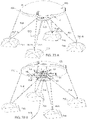
- the float assembly is anchored within the body of water by at least three cables connecting the float assembly to a ballast mounting attachment.
- the system may further include an automated winch assembly associated with each cable and configured to automatically control the length of the cable between the float assembly and the respective ballast mounting attachment so as to control the orientation of the float assembly and the at least one hub, the one or more articulating plates, and the articulation control system buoyantly supported thereby.
- system may further include a perimeter plate fixed to the hub carrier and disposed between each hub and the axially-adjacent hub and thrust bearings disposed between the perimeter plate and the hub and between the perimeter plate and the axially adjacent hub.
- system may further include a brake housing surrounding the hub carrier and fixed with respect to the hub carrier, wherein the brake housing is directly or indirectly coupled to an axially end-most one of the two or more hubs and thrust bearings between the brake housing and the axially end-most hub.
- the follower assembly is physically connected to an associated shaft.
- the follower assembly is magnetically coupled to an associated shaft.
- each articulating plate comprises a shaft rotatably mounted to the hub and defining the articulation axis of the associated plate
- the articulation control system may include a first magnetic array, a second magnetic array spaced apart from the first magnetic array and of opposite polarity than the first magnetic array, a magnetized follower coupled to the shaft and disposed at least partially in the space between the first magnetic array and the second magnetic array, and a controller adapted to selectively control the magnetic force of one or more portions of at least one of the first and second magnetic arrays to effect selective movement of the magnetic follower to cause rotation of the associated articulating plate.
- each articulating plate may include a shaft rotatably mounted to the hub and defining the articulation axis of the associated plate
- the articulation control system may include one or more motors operatively coupled to each of the shafts and controlled to effect selective rotation of the associated shaft.
- each articulating plate is mounted to an associated shaft defining the plate articulation axis, and may further include first and second stops attached to the shaft at angularly-spaced positions.
- the first stop is configured to prevent the associated articulating plate from rotating about the plate articulation axis beyond a first orientation
- the second stop is configured to prevent the associated articulating plate from rotating about the plate articulation axis beyond a second orientation.
- each articulating plate may include a shaft rotatably mounted to the hub and defining the articulation axis of the associated plate
- the articulation control system may include a lubricant-filled chamber, a fixed track assembly disposed within the lubricant-filled chamber and having a continuous track about its perimeter, wherein the continuous track circumscribes the hub axis of rotation, a follower assembly associated with each articulating plate and disposed within the lubricant-filled chamber and engaged with the continuous track, an outer magnetic coupling connected to each shaft and disposed outside of the lubricant-filled chamber, and an inner magnetic coupling connected to the follower assembly and disposed within the lubricant-filled chamber.
- the inner magnetic coupling is magnetically coupled to the outer magnetic coupling through a wall of the lubricant-filled chamber so that as the hub and articulating plate rotate about the hub axis of rotation the follower assembly traverses the continuous track and varies the orientation of the plate with respect to the articulation axis of the plate.
- one of the stationary track member and the movable track member includes a female conical mating surface and the other of the stationary track member and the movable track member includes a male conical mating surface, so that the stationary track member and the movable track member are self-aligning.
- the continuous track includes a first section, a second section, and first and second transition sections between the first and second sections and wherein, as the follower assembly traverses the first section of the track, engagement of the follower assembly with the first track section causes the associated plate to assume a first orientation with respect to the articulation axis of the plate, as the follower assembly traverses the second section of the track, engagement of the follower assembly with the second track section causes the associated plate to assume a second orientation with respect to the articulation axis of the plate, as the follower assembly traverses the first transition section of the track, engagement of the follower assembly with the first transition section causes the associated plate to transition from the first orientation with respect to the articulation axis of the plate to the second orientation with respect to the articulation axis of the plate, and as the follower assembly traverses the second transition section of the track, engagement of the follower assembly with the second transition section causes the associated plate to transition from the second orientation with respect to the articulation axis of the plate to
- the first section of the track lies in a first plane that is perpendicular to the hub axis of rotation
- the second section of the track lies in a second plane that is perpendicular to the hub axis of rotation
- the first and second sections of the track are axially spaced apart with respect to the hub axis of rotation.
- opposed sides of the continuous track have an opposite magnetic polarity and the follower assembly includes a follower head disposed within the continuous track and magnetized so that opposed sides of the follower head have a magnetic polarity opposite the magnetic polarity of the side of the continuous track facing that side of the follower head.
- the continuous track has a circular cross-sectional shape and the follower head has a spherical shape.
- the opposed surfaces are oriented perpendicular to the plane of rotation of the hub during the second portion of each rotation of the hub.
- the system may include a plurality of articulating plates disposed at angularly-spaced positions about the hub and wherein adjacent articulating plates that are in their slipstream orientations overlap one another, and each articulating plate has a leading edge pocket of reduced thickness on a first surface of the plate and a trailing edge pocket of reduced thickness on a second surface of the plate, and the leading edge pocket of one articulating plate nests with the trailing edge pocket of an adjacent overlapped articulating plate when the plates are in their slipstream orientations.
- the system may further include a hub orientation control system.
- the hub orientation control system may include a sensor detecting a direction of a fluid flow transverse to the hub axis of rotation; and one or more actuators configured to reposition the hub about the hub axis of rotation so that the articulating plates are in their slipstream orientations for the first portion of each rotation of the hub in a direction against the direction of fluid flow and so that the articulating plates are in their working orientations for the second portion of each rotation of the hub in a direction with the direction of fluid flow.
- the system may further include a cowling surrounding the at least one hub, wherein a part of the cowling associated with each hub is closed on a side of the cowling corresponding to the first portion of the hub's rotation and includes an intake port and an exhaust port on a side the cowling corresponding to the second portion of the hub's rotation.
- each plate has opposed surfaces, a leading edge, and a trailing edge
- the articulation control system is configured to orient each plate in a slipstream orientation in which the opposed surfaces of the plate are parallel to the plane of rotation of each hub for a first portion of each rotation of the hub and in a working orientation in which the opposed surfaces are not parallel to the plane of rotation of the hub for a second portion of each rotation of the hub.
- the system may further include a cowling surrounding the two or more hubs, wherein a part of the cowling associated with each hub is closed on a side of the cowling corresponding to the first portion of the hub's rotation and includes an intake port and an exhaust port on a side the cowling corresponding to the second portion of the hub's rotation and a separator plate disposed within the cowling between each hub and at least one axially-adjacent hub, and the separator plate is fixed with respect to the hub axis of rotation and is configured so as not to interfere with rotation of the articulating plates with the hub about the hub axis of rotation or articulation of the articulating plates about their respective axes of rotation.
- the system may further include a secondary override ring with lifters coupling the primary override ring to the secondary override ring, a tertiary override ring with lifters coupling the secondary override ring to the tertiary override ring, so that the primary override ring, the secondary override ring and the tertiary override ring move axially in unison, and an actuator cam attached to the shaft of each articulating plate of the axially adjacent one of the hubs and configured to be contacted by the axially moving tertiary override ring and retain each articulating plate of the axially adjacent hub at its slipstream orientation.
- the linear actuator comprises a ball screw actuator.
- the articulation override system may include one or more redundant actuators configured and controlled to cause axial movement of the primary override ring if the one or more linear actuators fail to axially separate the stationary track member from the movable track member.
- the redundant actuators comprise one or more actuators selected from the group consisting of pyrotechnic actuators, pneumatic actuators, hydraulic electronic solenoid actuators actuators, and piston actuators,
- the redundant actuator is configured to be actuated by an electrical device, explosive device, a pressure cartridge, a mechanical primer-initiated device, a linear detonation transfer line, or a laser actuated ordnance device.
- system may further include a power take-off device operably coupled to the at least one hub and configured to receive mechanical energy from rotation of the at least one hub.
- the power take-off device may include one or more of a clutch, a gearbox, an electrical generator, and a pump.
- aspects of the disclosure are embodied in a method for converting kinetic fluid energy to mechanical energy with a hub that is rotatable about a hub axis of rotation and one or more articulating plates extending radially from the hub and rotatable therewith.
- the method may include the steps of A. selectively articulating each articulating plate about a plate articulation axis that is oriented radially with respect to the hub axis of rotation, and B. during step A, independently controlling an orientation of each plate with respect to the associated plate articulation control axis so that the orientation of the plate changes as the hub rotates about the hub axis of rotation.
- each plate has opposed surfaces, a leading edge, and a trailing edge
- step B comprises orienting each plate so that the opposed surfaces of the plate are parallel to the plane of rotation of the hub for a first portion of each rotation of the hub and so that the opposed surfaces are not parallel to the plane of rotation of the hub for a second portion of each rotation of the hub.
- the opposed surfaces are oriented perpendicular to the plane of rotation of the hub during the second portion of each rotation of the hub.
- the method may further include placing the hub in a fluid flowing in a direction that is transverse to the hub axis of rotation, and wherein the plate is moving against the direction of fluid flow for the first portion of each rotation of the hub and the plate is moving with the direction of fluid flow for the second portion of each rotation of the hub.
- each plate transitions between its orientation during the first portion of the rotation and its orientation during its second portion of the rotation.
- This description may use relative spatial and/or orientation terms in describing an absolute or relative position and/or orientation of a component, apparatus, location, feature, or a portion thereof. Unless specifically stated, or otherwise dictated by the context of the description, such terms, including, without limitation, top, bottom, above, below, under, on top of, upper, lower, left of, right of, in front of, behind, next to, adjacent, between, horizontal, vertical, diagonal, longitudinal, transverse, radial, axial, etc., are used for convenience in referring to such component, apparatus, location, feature, or a portion thereof in the drawings and are not intended to be limiting.
- any specific dimensions mentioned in this description are merely representative of an exemplary implementation of a device embodying aspects of the disclosure and are not intended to be limiting.
- the terms “fixedly linked,” “operationally connected,” “operationally coupled,” “operationally linked,” “operably connected,” “operably coupled,” “operably linked,” “operably couplable” and like terms refer to a relationship (mechanical, linkage, coupling, etc.) between elements whereby operation of one element results in a corresponding, following, or simultaneous operation or actuation of a second element. It is noted that in using such terms to describe inventive embodiments, specific structures or mechanisms that link or couple the elements are typically described. However, unless otherwise specifically stated, when one of such terms is used, the term indicates that the actual linkage or coupling take a variety of forms, which in certain instances will be readily apparent to a person of ordinary skill in the relevant technology.
- KFECS refers to any embodiment of a kinetic fluid energy conversion system described herein, including without limitation, embodiments used for converting wind energy or water energy to mechanical energy, irrespective of the orientation of the longitudinal axis (axis of rotation) of the hub carrier relative to the land or land-based structure upon which the KFECS is located, or the water surface under which the KFECS is located.
- bearing refers to a component used to support and/or guide a rotating, oscillating, articulating or sliding shaft, pivot, wheel or assembly. Irrespective of the bearing described or shown, it may take on numerous forms, including without limitation sealed, unsealed, roller, ball, angular, needle and thrust. However, unless otherwise specifically stated, when such term is used, the term indicates that the actual linkage or coupling take a variety of forms, which in certain instances will be readily apparent to a person of ordinary skill in the relevant technology.
- the terms "computer,” “computer-controlled and like terms refer to a computer and/or redundant computer(s) within or connected to the KFECS irrespective of its physical location, that may include one or more uninterruptible power supplies.
- the term "land-based system” refers to a KFECS that is intended to convert kinetic fluid energy from a moving gas or gaseous mixture, including, without limitation, air, to mechanical energy.
- water-based system refers to a KFECS that is intended to convert kinetic fluid energy from a moving liquid, or liquid mixture, including without, limitation, water, to mechanical energy.
- independent control refers to the rotation of an energy conversion plate, relative to its axis, independent of, and unrelated to, any other energy conversion plate included within the KFECS.
- clutch/gearbox/electrical generator/pump assembly refers to any device or assembly of components that may be operably coupled to the KFECS and which may be driven by mechanical energy that flows from the KFECS.
- energy conversion plate when used in a land-based system, are commonly known as airfoils, and when used in a water-based system, are commonly known as hydrofoils.
- ECP energy conversion plate
- the term “nesting ECP” refers to an ECP that, when all ECPs are in their slipstream orientation, are configured such that the ECP's leading edge parallel to the ECP's axis overlaps and nests with the ECP that is immediately ahead of it in its direction of rotation about the longitudinal axis of the hub carrier.
- working mode refers to the orienting of an energy conversion plates whereby they are not parallel to - and may be perpendicular - to the fluid flow and will convert kinetic fluid energy to mechanical energy when subjected to an oncoming fluid flow.
- slipstream orientation refers to the orienting of energy conversion plates whereby they are parallel to an oncoming fluid flow and will not convert kinetic fluid energy to mechanical energy when subjected to an oncoming fluid flow.
- AOS refers to an articulation override system that comprise multiple redundant systems that enable the KFECS to articulate all ECPs to their slipstream position and stop the rotations of the hubs.
- AOS standby mode refers to the operation of the AOS system whereby it (i) is monitoring the KFECS for conditions incompatible with the KFECS working mode, and (ii) has all moving parts retracted or otherwise in a position or state where such parts are not subjected to mechanical wear.
- AOS active mode refers to the operation of the AOS whereby all energy conversion plates are moved to and/or retained in their slipstream orientations.
- the term "stopped mode” refers to the reorienting of all energy conversion plates (i) to their parallel to the flow (slipstream) orientations whereby they will not convert kinetic fluid energy to mechanical energy when subjected to a fluid flow, (ii) to a position whereby the KFECS can withstand fluid speeds and pressures far in excess of its design limit, and (iii) whereby the rotation of the KFECS is stopped for maintenance or any other purpose.
- AOS Triggering Event refers to any event that causes an AOS primary, or failsafe operation to occur. Triggering events include, without limitation, a signal received by the computer indicating (i) the fluid speed exceeds the KFECS's design specification, (ii) an error condition is detected by one or more sensors within the KFECS where such error condition require the KFECS's rotations to cease, (iii) maintenance of, or relating to, the KFECS is required or requested by the AOS or a maintenance crew, or (iv) any other specified condition is met.
- all such components may be manufactured using conventional (i) assembly techniques whereby a single component may be split into multiple parts and, when reassembled, embody the characteristics of the component described herein and/or shown in the drawings, and (ii) weight saving methods, including without limitation designing all such components, including without limitation ECP 10, ECP 20, hub 120, hub carrier 130, hub 180, perimeter plate 215, brake housing 121, base 900 and cowling 1000, in multiple sub-assemblies, which can be assembled with conventional assembly techniques, into the particular component as shown.
- All components may also have an interior lattice-like, or other non-solid interior design with strengthened and/or thickened areas where required, for example at areas in contact with bearings, and an external skin whereby such components may appear to be solid when in fact they need not be to achieve their desired functionality.
- KFECS kinetic fluid energy to mechanical energy conversion system
- hubs capable of being operably coupled to one or more counter-rotating adjacent hubs, with each hub including one or more independently controlled articulating energy conversion plates.
- Embodiments disclosed herein and shown on accompanying figures support the configuration of one or more clutch/gearbox/electric generator and/or pump assemblies on or near the ground, for a land-based KFECS, and near or above the water surface, for a water-based KFECS.
- Embodiments disclosed herein and shown on accompanying figures permit positioning a longitudinal axis of a hub carrier as described herein in any orientation relative to the land or land-based structure upon which the KFECS is erected, or water in which the KFECS is erected, including without limitation, horizontal, or vertical.
- the operably coupled clutch/gearbox/electrical generator or pump assembly(ies) may be located at or near the ground, or floor as the case may be, for a land-based KFECS, and at or near the water surface, for a water-based KFECS.
- Embodiments disclosed herein and shown on accompanying figures are also related to the independent control of an energy conversion plate by articulation of it about a rotational axis that is substantially parallel to the plane of the ECP to achieve optimal energy conversion, while an energy conversion plate is moving in the direction of the fluid flow and to encounter minimal drag while moving against the fluid flow.
- adjustment of the energy conversion plate articulation can be automatically overridden by an Articulation Override System (AOS) which causes each energy conversion plate, irrespective of the angular position about the hub carrier where it is located or traveling, to articulate to a position parallel to the fluid flow, and then causes all hubs and to cease rotating about the hub carrier (KFECS stopped position).
- AOS Articulation Override System
- Embodiments disclosed herein permit multiple configurations of size and shape of KFECS components, including without limitation (i) differing aspect ratios of ECPs, and (ii) KFECS vertical, horizontal or their orientations relative to the ground or water bottom. Moreover, the descriptions and drawings are not intended to be limiting with respect to a KFECS physical shape, size, installation location or fluid type in which a KFECS is operating.
- the kinetic fluid energy conversion system (“KFECS”) is based upon an integral hub carrier, with one or more rotating operationally coupled hubs rotating around the hub carrier, with each hub having equally-spaced, independently-articulating, fully controlled energy conversion plates (“ECP”) located around the hub's perimeter.
- the hub carrier remains oriented directly to the oncoming fluid flow, or any other computer-controlled orientation, via hub orientation control system comprising, in an embodiment, one or more computer-controlled hub orientation control motors.
- Each energy conversion plate is independently controlled from within its respective hub and synchronized with the system's revolutions, such that each energy conversion plate can be oriented for optimum overall energy conversion while moving in the direction of the fluid flow, and then articulated to be oriented for minimum drag, while the energy conversion plate is blocked from the fluid flow or moving against the flow.
- Different numbers of hubs can be configured in different aspect ratios (height to width) to support a variable range of installation conditions and/or designer's choice, including without limitation fluid speed, fluid type, ECP types and shapes.
- Different numbers ECPs can be configured in multiple desired geometric shapes to achieve overall KFECS operating characteristics, including without limitation the desired aspect ratio of the energy conversion system, mechanical energy output desired, and the overall energy conversion system size.
- All KFECS hub embodiments may be operably coupled to one or more power take-offs, including without limitation clutch/gearbox/generator or pump assemblies.
- the operable couplings may be computer controlled to selectively and individually couple and decouple to the KFECS to achieve a range of loads enabling the KFECS to operate in a wide range of fluid speeds.
- only one of the multiple gearbox/generator assemblies may be coupled, for example by an engaged clutch, to the KFECS during low fluid speed operating conditions while two or more or all of the gearbox/generator assemblies may be coupled to the KFECS during relatively high fluid speed operating conditions.
- KFECS embodiments may have a lower cut-in speed (the minimum speed at which a fluid energy conversion system begins to convert energy, typically by rotating or moving, sufficiently to rotate a generator or pump). KFECS lower cut-in speed results from the much larger square area of fluid conversion surface (ECPs) that may be configured in a given volumetric area, and the time over which the ECPs are in contact with the fluid flow as described herein, as compared to traditional wind and water kinetic energy conversions systems configured within the same volumetric area.
- ECPs fluid conversion surface
- KFECS embodiments may also have a higher cut-out speed (the speed at which wind powered kinetic energy conversion systems, such as conventional horizontal and vertical axis wind turbines, are either attempted to be brought to rest or otherwise subjected to a lesser amount of dynamic pressure in an attempt to prevent damage to such systems.
- the embodiments described herein permit higher cut-out speeds as a result of its integral internal supporting structure and hub design, the plurality of which may be configured to be greater than twenty percent of the total area exposed to an oncoming fluid flow.
- Embodiments described herein include an ECP tip speed that may never exceed the fluid speed and consequently rotates at a low RPM thereby (i) reducing wear on energy conversion components and related parts, and (ii) possibly reducing the risk of moving parts injuring birds and other flying animals, when used in air, or marine life, when used in water.
- each ECP is configured at 72-degree intervals about the hub, with the 0 degree positioned located nearest the oncoming fluid flow.
- the first ECP in this embodiment moves in a rotation about the hub carrier's longitudinal axis, in the direction of the fluid flow, it will begin to convert kinetic fluid energy to mechanical energy after it passes the 0-degree position, increasing its energy conversion output through the 90-degree position, and then decreasing its energy conversion output to the 120-degree position. After passing the 120-degree position, the fluid flow toward the ECP will be completely blocked by the following, adjacent, ECP.
- the first ECP in this example is then articulated to its 0-degree (angle of attack) slipstream orientation where the surfaces of the ECP will be substantially parallel to the fluid flow.
- the ECP Once the ECP passes the 180-degree position, it will remain in its parallel to the flow (slipstream) orientation while it rotates against the oncoming fluid or until it otherwise reaches the angular position at which the articulation control system is configured to begin controlled articulation of the ECP to its perpendicular (90 degree angle of attack) to the fluid flow (working) orientation.
- each energy conversion plate is controlled at all times by components within its respective hub.
- that articulation control system comprises a split track assembly comprised of a stationary section and a movable section joined together to form a continuous track.
- the track assembly is fixed to the hub carrier so that it acts as a part of the hub carrier, immovable from the hub carrier while the KFECS is its working mode, and rotating with the hub carrier when the hub carrier is rotated by the hub orientation control system.
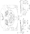
- the stationary and moveable sections of the track assembly are connected by splines around its circumference, as shown in FIGS. 2B - 2C , and are followed by a follower assembly operably linked to the energy conversion plate shaft of the respective energy conversion plate.
- each section of the track assembly, and the follower assembly that travel within it are magnetically charged and arranged so a spherical magnetic assembly levitates within the spherical magnetic track.
- the energy conversion plate will cause the operably coupled hub to rotate about the hub carrier in the direction of the fluid flow and consequently, the energy conversion plate, operably linked shaft and operably coupled hub will rotate around the track assembly.
- the follower assembly moves into a spline within the magnetic track, in this example, FIG.
- Each hub may be operably coupled to one or more counter-rotating hubs thereby transferring mechanical energy between them to a clutch/gearbox/electrical generator or pump assembly.
- One coupling method is achieved via a synchronous gear mesh.
- each hub is fitted with a ring gear, with pinion gears meshed between each ring gear.
- This arrangement embodies a counter-rotating transmission which enables an evenly distributed load across the hub carrier and a synchronized counter-rotation of the meshed hubs.
- the counter-rotating transmission is designed and configured to work in any hub carrier longitudinal axis orientation, including horizontal, and vertical. However, when used in a vertical axis orientation, all gear surfaces can be immersed in a reservoir suitable for holding liquid lubricant, while not requiring any seals about rotating shafts or between components located under the liquid lubricant level.
- a computer-controlled articulation override system provides a series of failsafe mechanisms to automatically override the articulation control of all energy conversion plates in the event the fluid speed exceeds the design specification, error conditions are detected, maintenance is required, or any other specified condition is met, and stop the rotation of the energy conversion system.
- Moveable and lockable rings, and related components, contained within each hub remain in their respective retracted position during normal operations whereby they are not subjected to any wear. When actuated, the rings travel along the hub carrier axis and engage, through the counter-rotating hubs, and may slide against and move against any cam operably linked to an energy conversion plate shaft that is not in a slipstream orientation. Simultaneously, the operationally coupled cam track separates to permit each follower assembly to travel to its slipstream orientation, irrespective of the radian about the hub carrier's longitudinal axis it is moving through or is at which it is stopped.
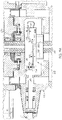
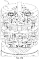
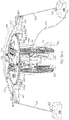
- the kinetic fluid energy conversion system (“KFECS”) 100 has an integral hub carrier 130, which may comprise a central shaft, with two or more counter-rotatable hubs 120 and 180 carried co-axially on the hub carrier 130 and mounted for rotation in opposite directions about a longitudinal axis of the hub carrier 130 (a hub axis of rotation 131 ).
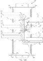
- a perimeter plate 215 is rotationally fixed to the hub carrier 130 and is disposed between hubs 120 and 180 (see FIGS. 7A and 13A ).
- Each such hub 120 and 180 has equally-spaced, internally controlled, independently-articulating energy conversion plates 10 (ECP) located around the respective hub's 120 and 180 perimeter and each ECP 10 is operably coupled to the respective hub by an associated shaft 140 extending radially from the hub to effect fluid flow-powered rotation of the respective hub.
- ECP energy conversion plates 10
- the ECP 10 will generate a torque applied to the respective hub 120 , or hub 180 , thereby causing the respective hub 120 or hub 180 to rotate about the hub carrier 130 .
- Hubs 120 and 180 may be provided in pairs of counter rotating hubs - one hub 120 or 180 of the pair rotating in a clockwise direction and the other hub 120 or 180 of the pair rotating in a counterclockwise direction - to balance torsional loads generated by each hub.
- each hub/ECP assembly will be rotating with the direction of the fluid flow for half of its rotation and against the direction of the fluid flow for the other half of its rotation.
- each ECP 10 is articulated so as to maximize the surface area exposed to the fluid flow during at least part of the rotation in the direction of the fluid flow and is articulated to minimize the surface area exposed to the fluid flow during at least part of the rotation in the direction against the fluid flow. In the embodiment illustrated in FIG.
- the ECPs 10 on the left side of the hub carrier 130 are articulated (about a plate articulation axis) so as to maximize the surface area exposed to the fluid flow while the ECPs 10 on the right side of the hub carrier 130 are articulated (about the plate articulation axis) to minimize the surface area exposed to the fluid flow.
- the ECPs 10 on the right side of the hub carrier 130 are articulated so as to maximize the surface area exposed to the fluid flow while the ECPs 10 on the left side of the hub carrier 130 are articulated to minimize the surface area exposed to the fluid flow.
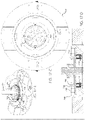
- the hub carrier 130 and the KFECS 100 remain oriented directly toward the oncoming fluid flow while in its working mode via a hub orientation control system that may include one or more fluid direction sensors 810 and one or more computer-controlled hub orientation control motors (“hub orientation control motors”) 710 having drive gears engaged with the orientation gear 700 attached to the hub carrier 130 (see FIG. 17A ).
- a hub orientation control system may include one or more fluid direction sensors 810 and one or more computer-controlled hub orientation control motors (“hub orientation control motors”) 710 having drive gears engaged with the orientation gear 700 attached to the hub carrier 130 (see FIG. 17A ).
- each ECP 10 is independently, fully and continuously controlled by an articulation control system that, in various embodiments, is located within the respective hub 120 or 180.
- Each ECP 10 is also synchronized with its respective hub's revolutions about the hub carrier 130, such that each ECP 10 can be oriented by the articulation control system for energy conversion while such ECP 10 is moving in the direction of the fluid flow, and then articulated to be oriented by the articulation control system for minimum drag while such ECP 10 is blocked from the fluid flow or moving against the fluid flow.
- Such a KFECS 100 converts kinetic fluid energy to positive mechanical energy when a fluid flow acts upon an ECP 10 that is (i) not parallel to the fluid flow, including without limitation perpendicular to it, and (ii) positioned and/or moving in the direction of the fluid flow, thereby causing the fluid pressure against the ECP 10 to rise.
- ECP 10 causes its respective hub 120 or hub 180, as the case may be, to rotate about the longitudinal axis of the hub carrier 130 .
- Positive mechanical energy is transferred to the hub 120 and hub 180 during any period in which the angle of attack of one or more of its respective ECPs 10 is not parallel to the fluid flow and moving in the direction of the fluid flow referred to herein as "working mode.”
- the articulation control system is configured so that when the fluid flow to an ECP 10 is blocked by a following, adjacent ECP 10, or an ECP 10 reaches the 180° position about the hub carrier 130, where the ECP 10 transitions from moving with the fluid flow to moving against the fluid flow, the ECP 10 will be articulated by the articulation control system described in Sections 2 and 9 herein about its respective shaft 140 axis from its energy converting working orientation (e.g., the ECP 10 surface is not parallel to and may be perpendicular to the fluid flow, or not parallel, and possibly perpendicular to, the plane of rotation of the hub) to its parallel to the flow "slipstream" orientation (or parallel to the plane of rotation of the hub), independently of all other ECPs 10 , whereby the ECP 10 is oriented to generate minimal drag as it rotates about the longitudinal axis of the hub carrier 130 in a direction against the fluid flow.
- the energy converting working orientation e.g., the ECP 10 surface is not parallel to and may be perpendicular
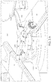
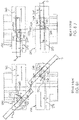
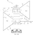
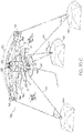
- FIG. 1A comprises a configuration with five ECPs 10 per each of two hubs 120 and 180.
- the axis of each ECP 10 (defined by shaft 140 ) is spaced at 72° intervals around the respective hub's 120 and 180 perimeter.
- each ECP 10 would be spaced at 60° intervals around the respective hub's 120 and 180 perimeter(s) such that the axis of each ECP 10 would be evenly spaced around such perimeter.
- 0° relative to the oncoming fluid flow for the KFECS 100 is based upon the orientation of the hub carrier 130 to the oncoming fluid flow.
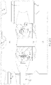
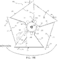
- FIG. 1B shows only the counter clockwise rotating hub 180 .
- a hub 180 When a hub 180 is rotating in a counterclockwise rotation, as a first ECP 10 in this embodiment (i.e., a five-ECP hub) moves in a counterclockwise rotation about the longitudinal axis of the hub carrier 130 , after it passes the 0° position it will be traveling in the direction of the fluid flow. As the first ECP 10 passes the 0° position, the articulation control system will orient the ECP so as to maximize surface exposure to the oncoming fluid by the time the ECP 10 reaches an angular position of about 355° (measuring backwards from 360°) and will begin to convert kinetic fluid energy to mechanical energy.
- a first ECP 10 in this embodiment i.e., a five-ECP hub
- the articulation control system will orient the ECP so as to maximize surface exposure to the oncoming fluid by the time the ECP 10 reaches an angular position of about 355° (measuring backwards from 360°) and will begin to convert kinetic fluid energy to
- the ECP 10 As the ECP 10 approaches the 180° position transitioning from moving with the flow to moving against the flow, the ECP 10 is then articulated by the articulation control system, as described in Sections 2 and 9, to its slipstream orientation where the ECP 10 will be parallel to the fluid flow. Once the ECP 10 passes the 180° position, it will remain in its parallel to the flow (slipstream) orientation while it rotates against the oncoming fluid flow or until it otherwise reaches the angular position where it is configured to begin its controlled articulation to its perpendicular to the fluid flow (working) orientation.
- Clockwise rotating hub 120 will articulate to maximum surface exposure at an angular position of about 5° and will articulate to minimum surface exposure after an angular position of about 127°.
- FIGS. 2A-2G Articulation Control System - Working Principle
- each ECP 10 is controlled at all times by components that may be enclosed within its respective hub 120 or hub 180.
- orientation of each ECP 10 is positively controlled by a follower mechanism engaged with a cam surface that effects articulation of the ECP 10 to varying predetermined orientations, relative to the fluid flow, as the ECP 10 rotates about the longitudinal axis of the hub carrier 130.
- orientation of each ECP 10 is positively controlled by computer-controlled motor that effects articulation of the ECP 10 to varying predetermined orientations, relative to the fluid flow, as the ECP 10 rotates about the longitudinal axis of the hub carrier 130.
- orientation of each ECP 10 is positively controlled by computer-controlled magnetic array that effects articulation of the ECP 10 to varying predetermined orientations, relative to the fluid flow, as the ECP 10 rotates about the longitudinal axis of the hub carrier 130.
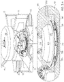
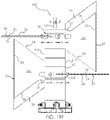
- a cam track assembly 250 includes an upper stationary section 251 and a lower moveable section 252 (in alternate configurations, the cam track assembly 250 comprises a single, integral unit as well as multi-track variations).
- the cam track assembly 250 is fixed to the hub carrier 130 so that it acts as a part of the hub carrier 130, immovable from it while the KFECS 100 is its working mode, and rotating with the hub carrier 130 when the hub carrier 130 is rotated by the hub orientation control system.
- the cam track assembly 250 includes a continuous track 255 disposed around its circumference that includes upper track portion or section 260 and a lower track portion or section 270 with an angled spline portion 261 forming a transition section connecting the upper and lower track portions on one side of the cam track assembly 250 (see FIG. 2B ) and an angled spline portion 262 forming a transition section connecting the upper and lower track portions on an opposite side of the cam track assembly 250 (see FIG. 2D ).
- a follower assembly 254 is operatively engaged with the continuous track 255 .
- One follower assembly 254 is operably linked to the energy conversion plate shaft 140 of each ECP 10 .
- the follower assembly 254 traverses the continuous track 255 resulting in corresponding orientations of the ECP 10 as the ECP 10 completes a revolution about the longitudinal axis of the hub carrier 130 .
- the corresponding ECP 10 when the follower assembly 254 is disposed within the upper track portion 260, the corresponding ECP 10 is disposed in its working orientation perpendicular to the direction of fluid flow, and when the follower assembly 254 is disposed within the lower track portion 270 , the corresponding ECP 10 is disposed in its slipstream orientation parallel to the direction of fluid flow.
- the follower assembly 254 traverses the spline portion 261 from the lower track portion 270 to the upper track portion 260 ( FIG. 2F )
- the corresponding ECP 10 transitions from its slipstream orientation parallel to the direction of fluid flow to its working orientation perpendicular to the direction of fluid flow.
- the corresponding ECP 10 transitions from its working orientation perpendicular to the direction of fluid flow, to its slipstream orientation parallel to the direction of fluid flow.
- Follower assembly 254 includes a connecting rod 145 connected to and extending radially from the shaft 140 of the ECP 10 .
- Follower head 253 is connected to the end of a shaft 256 mounted to the connecting rod 145 at a radial distance from the shaft 140 .
- Shaft 256 may be rotationally mounted, defining an axis of rotation that is generally parallel to an articulation axis defined by the shaft 140 .
- the ECP 10 is in its slipstream orientation when the follower assembly is in the upper track portion and is in its working orientation when the follower assembly is in the lower track assembly, depending on how the follower assembly is operatively attached to the shaft 140 of the ECP 10 .
- the follower assembly 254 may include a linkage fixedly attached to the shaft 140 with a follower head 253 at a free end of the linkage disposed within the track 255 of the cam track assembly 250 .
- the follower head 253 is spherical in shape and the track has circular transverse cross-sectional shape generally conforming to, but having a larger diameter than, the follower head 253 .
- the upper section 251 and the lower section 252 are magnetically charged with opposite poles facing each other, and together comprise a magnetic track.
- the upper and lower sections can be magnetically charged by any suitable means, such as machining the upper and lower sections from permanent magnetic materials, embedding magnetic materials within nonmagnetic sections 251 and 252, or by application of electromagnetism.
- the spherical follower head 253 is also magnetically charged and travels within the magnetic track whereby like poles of the follower head 253 are oriented nearest its like pole in the magnetic track, thereby resulting in the follower head 253 levitating within the magnetic track and forming a magnetic bearing.
- each hub 120 and 180 may be operably coupled to one or more counter-rotating hubs 120 and 180 thereby enabling the transfer of mechanical energy between them and/or through them to one or more operably coupled power take-off devices, such as clutch/gearbox/electrical generator or pump assemblies 620 .
- One hub 120 to hub 180 counter-rotating coupling method is achieved via a counter-rotating transmission 240 which enables the transfer of mechanical energy between them and/or through them to one or more operably coupled power take-off devices, such as clutch/gearbox/electrical generator or pump assemblies 620 .
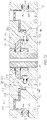
- transmission 240 comprises a ring gear 200 attached or otherwise operatively coupled to hub 120 and a ring gear 230 attached or otherwise operatively coupled to hub 180 (see Section 3 and FIG. 3A ).
- Transmission 240 further comprises radially oriented pinions 220 that are rotatably mounted to a pinion carrier 210 , which is fixed to the hub carrier 130 . This arrangement results in the center of the axis of each pinion 220 remaining at all times in the same angular position relative to the hub carrier 130 .
- each pinion 220 is fixed at an angular position with respect to the hub carrier 130 , rotational movement of either hub 120 and 180 about the longitudinal axis of the hub carrier 130 results in its operably linked respective ring gear 200 and ring gear 230 rotating about the longitudinal axis of the hub carrier 130. .
- Rotational movement of either ring gear 200 or ring gear 230 will cause the opposing ring gear to rotate in the opposite direction. Movement of either ring 200 or ring gear 230 will cause the operably coupled pinions 220 to rotate about their respective axes thereby causing an opposite rotation of the adjacent ring gear and operably coupled hub.
- the transmission 240 will operate irrespective of the orientation of the longitudinal axis the hub carrier 130 , including without limitation, horizontal and vertical. However, when used in a KFECS 100 with a hub carrier 130 that has a vertical axis orientation, all gear surfaces can be immersed in a reservoir suitable for holding liquid lubricant, while not requiring any seals about rotating shafts or between components located under the liquid lubricant level.
- a computer-controlled ECP 10 articulation override system (“AOS") provides a means to automatically override the primary articulation control of all ECPs 10 to protect the KFECS 100 from fluid flow that exceeds preset limits and/or to stop the KFECS 100 for maintenance or other purposes.
- AOS articulates all ECPs 10 to, and/or retains them in, a slipstream orientation (AOS Active Mode) until the AOS determines it is safe to return ECP 10 articulation control to the Primary Articulation Control System.
- AOS Standby Mode whereby the AOS continuously monitors sensors for any AOS active mode triggering event.
- AOS Active Mode Such triggering events include without limitation the computer's receipt of a signal indicating (i) the fluid flow speed exceeds the KFECS's 100 design specification, (ii) an error condition is detected by one or more sensors within the KFECS 100 where such error condition require the hub 120 and 180 rotations to cease, (iii) maintenance of, or relating to, the KFECS 100 is required or requested by the AOS or a maintenance crew, or (iv) any other specified condition is met. All AOS components, other than external kinetic fluid energy speed and direction sensors 810, may be enclosed within the counter-rotating hubs 120 and 180, hub carrier 130 or other areas of the KFECS 100 and do not come in contact with the fluid flow.
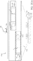
- An embodiment of the AOS includes moveable and lockable rings (see Section 10 and FIG. 15A ) including a primary ring 560, secondary ring 570 and tertiary override ring 580 contained within hub 120 and hub 180 which remain in their retracted positions during normal operations whereby they are not subjected to any wear.
- the shaft 140 of each ECP 10 includes a cam 590.
- the primary ring 560, secondary ring 570 and tertiary override ring 580 move in axial directions with respect to the hub carrier 130 and cause any cam 590 operably linked to an ECP 10 that is not in the AOS Slipstream Mode position to move into, and/or remain in, such position.
- the stationary section 251 and moveable section 252 of the cam track assembly 250 separate to permit each follower assembly 254 to travel to (or remain in) its slipstream position, irrespective of the angular position about the longitudinal axis of the hub carrier 130 the follower assembly 254 is moving through or at which it is stopped.
- the ECPs 10 remain in their slipstream orientations and, optionally, each hub 120 and hub 180 remains stopped until the AOS resumes its standby mode.
- an articulation control system is described below. All such embodiments are compatible with the AOS to achieve its functions of articulating the ECPs 10 to, and/or retaining them in, a slipstream orientation (AOS Active Mode) until the AOS determines it is safe return the ECP 10 articulation control to the Primary Articulation Control System.
- the AOS controls any embodiment of ECP, including, without limitation, nesting ECP 20 as described in Section 13.3. The detailed operations of the AOS are described in Section 10.
- kinetic fluid energy is converted into mechanical energy from any ECP plate 10 that is not parallel to the oncoming fluid flow by the resulting rotation of the corresponding hub 120.
- the mechanical energy is converted as a distributed load (pressure) across the ECP 10 and is transferred through its respective operably linked shaft 140, both of which act together as a lever thereby applying a torque to the counter-rotating hub 180, and causing the hub 180 to rotate.
- the mechanical energy is transferred out of the counter-rotating hub 180 through the transmission 240, and as described in more detail below in Section 7, into a operably coupled counter-rotating hub 120.
- the combined mechanical energy from both hubs 120 and 180 is transferred to any operably coupled device, such as a clutch/gearbox/electrical generator/pump assembly 620, for example, by means of bevel gear 600 and pinion gears 610, as described in more detail in Section 12.3.
- a clutch/gearbox/electrical generator/pump assembly 620 for example, by means of bevel gear 600 and pinion gears 610, as described in more detail in Section 12.3.
- the hub 120 and hub 180 and hub carrier 130 design may be scalable to include internal space to accommodate all of the bearings and primary articulation controls and related components necessary for the conversion of kinetic fluid energy to mechanical energy (collectively “Hub and Hub Carrier Components").
- the Hub and Hub Carrier Components may include (i) multiple hub carrier bearings 135 between hubs 120 and 180 and hub carrier 130 that permit the respective hub 120 and hub 180 to rotate around the longitudinal axis of the hub carrier 130, (see hub carrier longitudinal axis 131 on FIG 1A ) (ii) thrust bearings 190 for supporting the weight of the respective hub 120 or hub 180 when the hub carrier's 130 longitudinal axis is mounted vertically (the illustrated embodiment includes one thrust bearing 190 however, alternate embodiments may contain several), (iii) one or more ECP shaft bearings 175 supporting shaft 140 (see FIG.
- Computer-monitored sensors may include, without limitation, proximity, temperature and fluid level sensors for monitoring and/or detecting, (a) ECP shaft 140 articulation position, (b) ECP shaft 140 angular position about the longitudinal axis of the hub carrier 130, (c) counter-rotating operable coupling 240 fluid level, and (d) status and/or operating condition of the hub 120 and hub 180.
- Hub status and operating conditions may include but are not limited to (1) bearing conditions, (2) speed of revolutions about the longitudinal axis of the hub carrier 130, (3) KFECS 100 internal temperatures, (4) clearances between perimeter plate 215 and the hub 120 and hub 180, (5) clearances within the transmission 240, (6) transmission 240 rotations per minute, (7) bevel gear 600 and (8) operably coupled clutch/gearbox/electrical generator and/or pump assembly 620.
- An embodiment of hub 120 includes an attached hub end 121 with recesses that accommodate hub carrier 130 bearings, AOS components further described in Section 10 , and brake components further described in Section 12.2.
- An embodiment of hub 180 includes an attached hub end 181 with recesses that accommodate hub carrier 130 bearings and AOS components further described in Section 10.
- An embodiment of hub 120 and hub 180 may include components which support operable counter-rotating coupling assemblies, similar to those described in Section 7, on each end of hub 120 and hub 180 thus enabling additional hubs to be added to the KFECS 100 and thereby permitting an expanded range of KFECS 100 aspect ratios to serve a designer's choice.
- hub 120 and hub 180 have integral hub extensions 124 that house bearings 175 supporting shaft 140.
- Hub extension 124 may be received within a conforming recess 17 formed in the end of the ECP 10 or nesting ECP 20 as described in Section 13.3.
- each shaft 140 may include two stops 160 extending radially from the shaft 140 from angularly-spaced positions and which contact corresponding shoulders 155 formed internally to the hub 120 (or hub 180) at the limit of the shaft's 140 articulation from its working rotational position to its slipstream rotational position. Shoulders 155 and stops 160 also act as a failsafe method of preventing the shaft 140 from rotating past its designed maximum limits of rotation about the longitudinal axis of the shaft 140.
- FIGS. 7A, 7B 7. Counter-Rotating Transmission - FIGS. 7A, 7B
- hub 180 contains similar components found in hub 120 but rotates in the opposite direction due to the transmission 240, i.e., the ring gears 200 and 230 and the pinions 220.
- the pinions 220 are rotatably mounted to the pinion carrier 210, which is fixed to the hub carrier 130 such that the pinions 220 act as an extension of the hub carrier 130 and move with it when it is rotated about its longitudinal axis by the hub orientation control system.
- Ring gear 230 is attached or otherwise coupled to hub 180.
- the hub 180 has a conical pinion carrier relief 185 formed therein that accepts the pinion carrier 210 with sufficient clearance to rotate around the pinion carrier 210 without contacting it.
- the transmission well recess 235 housing the transmission 240 may be filled with a lubricating fluid, thereby permitting the transfer of mechanical energy between two counter-rotating hubs without the need for any fluid seals for rotating components or components located below the fluid level when the longitudinal axis of the hub carrier 130 is oriented vertically, and consequently, all ECP 10 control shafts 140 can be articulated without the need for lubricant seals related to the ring gear and pinion assembly.
- Proximity sensors 585 located on a perimeter plate 215 of the pinion carrier 210 can be used to determine KFECS 100 operations, including without limitation, the distance between hubs and potential wear of hub carrier bearings 135 .
- Exemplary proximity sensors 585 include digital inductive, 2 -wire amplified, digital CMOS laser, photo-electric, pattern matching and optical. Hub carrier bearing 135 wear can be detected when one or more proximity sensors 585 detect a distance between the perimeter plate 215 and its adjacent hub 120 or hub 180 that is out of a predetermined tolerance.
- the follower assembly 254 which is operably connected to the shaft 140 of each ECP 10 , or nesting ECP 20 described in Section 13.3 , is rotated about the shaft axis 140 , e.g., by 90 degrees, by the splines portions 261, 262 of the continuous track 255 of the cam track assembly 250 as the respective follower head 253 travels through the splines.
- the ECP 10 angle of incidence begins as parallel to the oncoming fluid flow (slipstream orientation, or 0° angle of attack) while at the 355° position.
- the follower assembly 254 rotates the associated ECP 10 from its slipstream orientation to its full articulation orientation of 90° perpendicular to the fluid flow ( 90° angle of attack).
- each ECP 10 independently articulates each ECP 10 such that its articulation is wholly independent of, unrelated to, and unconstrained by, any aspect of any other ECP 10 .
- the articulation of each ECP 10 may be controlled by any of the embodiments described in Section 9.
- the articulations of the ECPs 10 of the counter-rotating hubs 120 and 180 are synchronized whereby the ECPs of the two hubs cannot collide with each other.
- the synchronizations are accomplished and controlled by the cam track assembly 250, or other articulation control embodiment, within each hub 120 or hub 180 . This is demonstrated in FIGS.
- ECP 10 on the lower hub has been renumbered as ECP 8 and shown as transparent
- ECP 10 on the upper hub has been renumbered as ECP 9 and shown as transparent to avoid obscuring the detail of the cam track assembly behind it.
- ECP 8 of a lower hub moves clockwise with its follower control assembly 254 guided in the lower track 270
- ECP 9 of an upper hub disposed in a horizontal, slipstream orientation moves counterclockwise toward the ECP 8 with its follower control assembly 254 guided in the upper track 260 .
- Each ECP 8 and 9 has rotated about the respective cam track assembly 250 to the same angular position (0° in FIG. 8E ) as the respective follower assembly begins to traverse the spline sections 261 of the upper and lower track assemblies. As shown in FIG.
- the ECPs 8 and 9 synchronously articulate clockwise about their respective axes of rotation at angular positions that are offset with respect to each other. That is, as an example, the follower assembly of ECP 8 traverses spline section 261 from lower track section 270 to upper track section 260 between 0° and 5° angular position with respect to the lower cam track assembly 250 . Conversely, the follower assembly of ECP 9 traverses spline section 261 from upper track section 260 to lower track section 270 between 0° and 355° angular position with respect to the upper cam track assembly 250 .
- each ECP 8 and 9 has moved "past" the other in its rotation about the respective track assembly 250 while being articulated about its axis of rotation through the spline section 261.
- lower ECP 8 is at 5° angular position with respect to the lower cam track assembly 250 and moving clockwise away from ECP 9
- upper ECP 9 is at 355° angular position with respect to the upper cam track assembly 250 and moving counterclockwise away from the lower ECP 8 .
- the ECPs 8 and 9 do not contact each other during the articulation from the horizontal, slipstream orientation to the vertical, working orientation.
- ECP 8 of the lower hub, disposed in the vertical, working orientation is moving clockwise toward ECP 9 with its follower control assembly 254 guided in the upper track 260
- ECP 9 of the upper hub disposed in the vertical, working orientation is moving counterclockwise toward the ECP 8 with its follower control assembly 254 guided in the lower track section 270.
- Lower ECP 8 has rotated clockwise about the lower cam track assembly 250 to a position short of a full half rotation of 180° (e.g., 150°) as the ECP 8 enters the spline section 262 connecting upper track section 260 with lower track section 270.
- Upper ECP 9 has rotated counterclockwise about the upper cam track assembly 250 to a position short of a full half rotation of 180° (e.g., 210°) as the ECP 9 enters the spline section 262 connecting lower track section 270 with upper track section 260.
- 180° e.g., 210°
- the ECPs 8 and 9 synchronously articulate counterclockwise about their respective axes of rotation at angular positions that are offset with respect to each other.
- each ECP 8 and 9 has not yet "met" the other in its rotation about the respective cam track assembly 250 while being articulated about its axis of rotation through the spline section 262. As shown in FIG.
- the offsets of where the upper and lower ECP 10 or ECP 20 (see Section 13.3) articulations begin and end, relative to its adjacent ECP 10 on hub 120 and hub 180, are within a designer's choice for satisfying performance and installation requirements.
- the change in offset is accomplished, with respect to a cam track assembly 250, by altering where each such assembly is attached to the hub carrier 130 relative to the cam track assembly 250 in the adjacent hub 120 or hub 180.
- the change in offset is accomplished in embodiments using the magnetic array articulation or motorized articulation, described in Sections 9.3 and Section 9.6 respectively, by the computer.
- Increasing an articulation offset permits using ECPs 20 with aspect ratios that allow increased nesting capabilities as described in Section 13.3 and permits using ECPs 10 and ECPs 20 with differing materials properties.
- stiffer materials require less offset because the respective ECP 10 or nesting ECP 20 will have less flex while in its working orientation and consequently can have a reduced offset, thereby converting more energy without colliding with the adjacent counter-rotating ECP 10 or nesting ECP 20 due to flexing.
- the angle of the spline and angular extent over which it is applied are design parameters which can be set.
- the spline 262 of the cam track assembly 250 may be set at a relatively shallow angle, as there is no particular benefit to a rapid articulation of the ECP 10 and so as to minimize twisting moment applied to the follower assembly 254 and the ECP shaft 140.
- spline angle 261 may be set at a steeper angle to effect a rapid articulation of the ECP into its power generating orientation.
- ECPs 10 could likewise be transitioned to their working position prior to 0°, and in fact, it has been determined mathematically that ECPs 10 produce more overall power through an entire 360° rotation if the articulation from slipstream mode to working mode begins at approximately 355° and has completed its transition to working mode by 5°.
- the ECP 10 starts to encounter drag from 355° due to its working surface starting to transition while moving against the flow from 355° - 0° (half of its transition)
- the inventor has determined that the positive power from 0° - 5° more than offsets the negative power from 355°- 0°.
- each ECP rotates about its respective hub, its shaft 140 remains at a substantially fixed axial position with respect to the hub axis of rotation centered between the upper track section 260 and the lower track section 270 . While the follower head 253 of the follower assembly 254 of each ECP is traversing the upper track section 260 or the lower track section 270, the radial distance between the hub axis of rotation and the position on the connecting rod 145 at which the shaft 256 is inserted or otherwise attached or coupled to the connecting rod 145 remains unchanged.
- the radial distance between the hub axis of rotation and the connecting rod 145 will change. In one example, the radial distance will increase until it reaches the midpoint of the transition section of the upper and lower track, and then it moves back in toward the hub axis as it nears the end of the transition section.
- the shaft 256 and follower head 253 may be configured to be movable in an axial direction (relative to shaft 256 ) with respect to the connecting rod 145, thereby varying the distance between the follower head 253 and the connecting rod 145, while the radial distance between the track 255 and the hub axis of rotation remains constant through the transition areas 261, 262.
- the shaft 256 and follower head 253 may be fixed with respect to the connecting rod 145, while the radial distance between the continuous track 255 and the hub axis of rotation varies through the transition areas 261, 262.
- articulation control systems described in this disclosure may also include comparable provisions for accommodating variation in the radial positioning of a follower assembly with respect to the hub axis of rotation as the follower assembly traverses a transition section of a follower orientation control feature.
- These provisions may include alternate embodiments of connecting rod 145, similar to connecting rod 146 (See FIG. 12E and 15I ) that include bearings within an alternate embodiment of connecting rod 145.
- ECP 10 articulation control may be accomplished by numerous methodologies.
- the torsion moment that such articulation control can support can be increased by increasing the length of the follower assembly 254 or the follower assembly's 254 functional equivalent.
- FIGS. 9A and 9B 9.1 Interior Magnetic Cam Track Assembly - FIGS. 9A and 9B
- ECP 10 articulation control is achieved via a magnetic spherical split cam track assembly 250 comprised of a stationary magnetic track section 251, and moveable magnetic track section 252, each with opposite magnetic poles nearest its respective spherical track half, with a spherical magnetic follower head 253 within the track 255, for each operably coupled shaft 140.
- the spherical magnetic follower head 253 is arranged such that its magnetic poles are repelled by the magnetism of each track section 251 and 252. This arrangement of magnetic components results in the spherical magnetic follower head 253 levitating within the magnetic spherical cam track assembly 250 thereby creating a magnetic bearing.
- the spherical magnetic follower head 253 is operably coupled to, e.g., mounted on a shaft 256, which may be a sacrificial shaft as described below, of the follower assembly 254, which is operably linked to a shaft 140 of an ECP 10.
- the geometry of the continuous track 255 controls the position of each ECP 10 relative to the fluid flow throughout the ECP's 10 entire 360° rotation about the longitudinal axis of the hub carrier 130.
- the geometry of the track 255 may be configured to control the start, end, and duration of each ECP 10 articulation, with the minimum duration between the start and end point of each such articulation limited only by the diameter of the spherical magnetic follower head 253 relative to the angle of the steepest splines 261 and 262 through which the spherical magnetic follower head 253 travels.
- the radius of the follower cannot be larger than the radius of the spline.
- the spherical magnetic follower head 253 travels through the track 255 around the magnetic cam track assembly 250 , (i) while traveling through the upper track 260 it causes the operably coupled ECP 10 to remain in an orientation perpendicular to the fluid flow (working position), (II) while traveling through a spline it causes the operably coupled ECP 10 to articulate 90°, and (iii) while traveling through the lower track section 270 it causes the related ECP 10 to remain in an orientation parallel to the fluid flow (slipstream).
- each track section 251 and 252 has an opposing magnetic pole nearest the its respective track 255 half.
- FIG. 10 another embodiment of ECP 10 articulation control is achieved via an internal liquid-lubricant filled cam track assembly 300 comprised of an stationary section 301 and moveable section 302 .
- the track assembly 300 is split along the centerline of a track 303 having an upper track 325 and a lower track 326.
- the liquid-lubricant filled cam track assembly 300 includes membrane 322 that defines an interior chamber suitable for containing liquid lubricant.
- a spherical bearing travels in a circular track 303 and is operably linked to a shaft 317 rotationally supported in a bearing 315.
- the bearing 315 is operably coupled to an inner magnetic coupling 321 which glides over an interior surface of the membrane 322, but does not contact it, during normal operations.
- An outer magnetic coupling 323 glides over the exterior of the membrane 322, but does not contact it during normal operations, and is operably coupled to its associated inner magnetic coupling 321 via magnetic attraction of sufficient magnetic force, through the membrane 322 to permit the transfer of torque necessary to articulate the associated ECP 10. It should be appreciated that this arrangement permits the transfer of torque through the magnetic field in a seal-less configuration.
- the perimeter plate 215 may comprise computer monitored sensors, as further described in Sections 9.5 and 11, that would detect a leak in the membrane 322 thereby resulting in one or more computer-controlled operations, including without limitation, triggering the AOS.
- the outer magnetic coupling 323 is operably linked via a shaft 317, which may be a sacrificial shaft as described below, to a shaft 140 of the associated an ECP 10.
- Track 303 has a circular transverse cross-section to receive the spherical bearing 310.
- the geometry of the track 303 controls the position of each ECP 10 relative to the fluid flow throughout its entire 360° rotation about the longitudinal axis of the hub carrier 130.
- FIG. 11A - FIG. 11D and to FIG. 8 another embodiment of ECP 10 articulation control is achieved via a magnetic array assembly 370 which is installed in the same location as, and in lieu of, any type of cam track assembly, including a magnetic cam track assembly 250.
- the magnetic array assembly 370 is comprised of two opposing computer-controlled electromagnetic arrays 371 and 372.
- a magnetized follower 373 is operably linked to the shaft 140, of each ECP 10.
- Each magnetic array 371 and 372 has an opposing computer-controlled variable electromotive force, with the follower 373 also being magnetically charged, with its North pole side facing the North array 371 and its South Pole facing the South array 372.
- the computer can be located within the KFECS 100 or attached remotely to it by a wired or wireless connection.
- the computer using inputs from one or more fluid speed and direction sensors 810 (see FIG. 1A ) causes the electromagnetic force to be increased on segments of one array 371 and decreased on segments of the opposing array 372 sequentially in the direction of rotation as desired as the magnetized follower 373 passes through the arrays, thereby causing the magnetized follower 373 to change its position relative to the array assembly 370 , and consequently, articulate the shaft 140 and associated plate 10, relative to the fluid flow throughout its entire 360° rotation about the longitudinal axis of the hub carrier 130.
- This computer-controlled articulation embodiment permits the KFECS 100 to remain constantly optimally oriented toward the fluid flow by changing the beginning, duration and end-point of each ECP 10 articulation thereby eliminating the need for hub orientation control motors 710 and related components (See FIG. 1A Enlarged view).
- magnetic array assembly 370 during AOS slipstream mode, does not require any sacrificial parts due to mechanical failure, for example a failed split track operation as described in Section 10.4. Consequently, shaft 257 (see FIG. 11A ) is not sacrificial.
- cam track assembly 460 may be implemented as a magnetic cam track assembly, similar to magnetic cam track assembly 250 (see FIG. 9A ) or a liquid lubricant filled cam track assembly 300 (see FIG. 10 ).
- This embodiment is comprised of three continuous tracks assemblies that control the articulation of the ECP shafts 140 , an upper track assembly 463 , a center track assembly 473 , and a lower track assembly 483 - each with a lower track, and upper track, and two spline sections connecting the respective upper and lower tracks.
- upper track assembly 463 comprises a fixed track section 461 and a movable track section 462
- center track assembly 473 comprises a fixed track section 471 and a movable track section 472
- lower track assembly 483 comprises a fixed track section 481 and a movable track section 482
- a triple follower assembly 490 is comprised of a linkage 491, shafts 492, follower heads 253 , one or more bearings 493 (see also FIG. 15I ), connecting rod 494 and shaft 495 , which may be a sacrificial shaft, as described below.
- the combination of the three track assemblies 463 , 473 and 483 and a triple follower assembly 490 coupled to the tracks 463 , 473 , 483 triples the torsion moment that the triple cam track assembly 460 supports as compared to single-track assemblies by tripling the surface area of the follower heads 253 or spherical bearings 310 (see FIG. 10 ).
- the designer may increase or decrease the moment that a particular track assembly supports by reducing or increasing the number of tracks, e.g. a double or quadruple cam track assembly, while using the same fundamental design principles incorporated in the triple cam track assembly 460 and related triple follower assembly 490 .
- the triple cam track assembly 460 is fixedly linked to the hub carrier 130 .
- the ECP shaft 140 , the triple follower assembly 490 , and the center track assembly 473 are configured and arranged so that the axis of each ECP shaft 140 is equidistant from the upper track and lower track of the center track assembly 473 (i.e., the axis of each ECP shaft 140 bisects center track assembly 473 ).
- the triple follower assembly 490 includes three follower heads 253 (or three spherical bearings 310 if the triple cam track assembly is configured as a liquid-lubricant filled cam track assembly (see FIG.
- each follower head 253 being disposed within one of the upper track assembly 463 , the center track assembly 473 , and the lower track assembly 483 .
- the triple follower assembly 490 is configured so that the follower heads 253 are all located at the same circumferential position within their respective tracks 463 , 473 , 483 as the ECP shaft 140 rotates about the hub, so that the follower heads 253 simultaneously enter and exit the splines of the respective tracks 463 , 473 , 483 .
- the coplanar alignment is an essential element of the geometry necessary for proper operation of the triple follower assembly 490 and prevents it from binding within the respective tracks 463, 473 and 483.
- the triple cam track assembly 460 like the magnetic cam track assembly 250 and lubricant filled cam track assembly 300, uses the splined hub 280 when it moves from its closed position, shown in FIGS. 12A and 12B , to its open position shown in FIGS. 12C and 12D .
- the hub carrier 130 of the KFECS 100 operates as a superstructure component.
- the hub carrier 130 may include an integral chase 132 that can be used for routing any type of electrical cable, hose or pipe for transporting mixed fluids, gases, such as pneumatic or hydraulic lines (collectively “Transport System”) or similar components (collectively “Transport System”) through the entirety of the KFECS 100, and routing such Transport System through the counter-rotating hubs 120 and 180 without the need for rotatable couplings.
- the perimeter plate 215 is fixed to the pinion carrier 210 (connected to each other or a single, integral component) which is fixed to the hub carrier 130. Consequently, any Transport System that runs through the hub carrier chase 132 may branch off through the perimeter plate 215 to serve numerous systems, including without limitation, electronic sensors, motor, vacuum, and pressure lines. Additionally, rotatable electrical couplings, including without limitation brush slip rings may be configured between the perimeter plate 215 and the adjacent hubs 120 and 180 thereby permitting the transfer of high voltage routed from the hub chase 132 to each ECP shaft 140 that serves a respective ECP 10 or 20.
- a KFECS 100 embodiment with more than two hubs 120 and 180 may include an additional perimeter plate 215, and related transmission as described in Section 7, between each additional hub.
- Transport Systems may be routed over numerous physical routes between the hub carrier chase 132 and the circumference of the perimeter plate 215 . Several such physical routes are shown with a dashed line.
- the perimeter plate 215 and fixedly linked pinion carrier 210 have numerous features integral to the counter-rotation transmission described in Section 7 and the AOS described in Section 10 .
- Pinion shaft receiver bores 211 are formed at angularly spaced positions about an outer wall of the pinon carrier 210 and receive the shafts of the pinions 220 .
- Perimeter plate 215 includes an annular support flange 216 at its inner periphery at which the perimeter plate 215 connects to the pinion carrier 210 .
- Pinion openings 217 are formed in the annular support flange at angularly spaced positions corresponding to the positions of the pinion shaft receiver bores 211 and receive the pinions 220 .
- annular hub receiver ring 218 bordering the annular support flange 216 nests with hub 120 below the perimeter plate 215 and nests with hub 180 above the perimeter plate 215 .
- Annular support flange 216 is axially recessed with respect to the annular hub receiver ring 218 and the pinion carrier 210 , thereby forming an annular trough that nests within the transmission well recess 235 .
- the annular trough formed by flange 216 and the transmission recess 235 of the adjacent hub form a reservoir that can contain a liquid lubricant within which the pinions 220 positioned within the openings 217 are immersed.
- the reservoir does not require seals for retaining the liquid lubricant within the reservoir when the hub is operated in configuration in which the hub carrier 130 is oriented substantially vertically.
- An annular rib 221 projects axially above annular hub receiver rib 218 and the outer perimeter of the perimeter plate 215 and defines a recess beneath it which accepts a secondary ring 570 of an articulation override system as described in Section 10 .
- Tertiary ring lifter slots 219 formed in the annular rib 221 permit movement of a tertiary ring of the articulation override system as described in Section 10 .
- Proximity sensors 585 may be located on both sides of the perimeter plate in the locations shown, however, the locations and numbers of proximity sensors are not intended to be limiting an are shown as described as an embodiment.
- the words “below” and “above” as used herein are not intended to be limiting and are merely used to orient the reader to the drawing.
- an alternate embodiment of a perimeter plate 215-A includes all of the features and functionality embodied within perimeter plate 215 and further includes attachment points and/or supporting areas for (i) a second and/or additional counter-rotating transmission 245 (See FIGS. 3B and 7C ), and (ii) a thrust bearing 227 extending circumferentially about the perimeter plate 215-A near its outer perimeter.
- Perimeter plate 215-A includes outer pinion openings 222 formed in an annular support flange 228 at angularly spaced positions about the perimeter plate 215-A .
- a pinion shaft receiver bore 223 is aligned with each outer pinion opening 222 .
- Each shaft receiver bore 223 receives a shaft of an outer pinion 224 having a gear head that is disposed in an associated outer pinion opening 222 .
- Perimeter plate 215-A is configured to be used with alternate embodiments of hub 120 (120-A) and hub 180 ( 180-A), whereby the counter rotating hubs 120-A and 180-A are rotationally coupled by the outer pinions 224 , optionally in combination with pinions 220 (inner pinions) of transmission 240.
- transmission 245 comprises a ring gear 225 attached or otherwise operatively coupled to hub 120-A (to the top of hub 120-A as shown in FIGS. 3B and 7C ) and a ring gear 226 attached or otherwise operatively coupled to hub 180-A (to the bottom of hub 180-A as shown in FIGS. 3B and 7C ).
- the radially oriented outer pinions 224 rotatably mounted within the receiver bores 223 of the perimeter plate 215-A are disposed between the outer ring gears 225, 226. This arrangement results in the center of the axis of each outer pinion 224 remaining at all times in the same angular position relative to the hub carrier 130 .
- each outer pinion 224 is fixed at an angular position with respect to the hub carrier 130, rotational movement of either hub 120-A or 180-A about the longitudinal axis of the hub carrier 130 results in its operably linked respective outer ring gear 225 or outer ring gear 226 rotating about the longitudinal axis of the hub carrier 130 . Rotational movement of either outer ring gear 225 or outer ring gear 226 will cause the opposing ring gear to rotate in the opposite direction via the coupling of the outer pinions 224 .
- Two thrust bearings 227 may be provided and located against the perimeter plate 215- A, with one thrust bearing 227 positioned between the top of the perimeter plate 215-A and the bottom of top hub 180-A, and another thrust bearing 227 positioned between the bottom of the perimeter plate 215-A and the top of bottom hub 120-A (see FIG. 7C ).
- an alternate embodiment of brake housing 730, (730-A) includes a brake housing thrust bearing 731 disposed circumferentially within an annular groove or channel formed in the top of the brake housing 730-A between the brake housing 730-A and an alternate embodiment of the hub end 121-A .
- the brake housing thrust bearing 731 permits rotation of the hub end 121-A and the hubs 120-A and 180-A with respect to the brake housing 730-A about the hub carrier 130 .
- Brake housing thrust bearing 731 at the outer radial periphery of the of the brake housing 730-A and hub end 121-A also transfers lateral and vertical loads acting upon the hubs 120-A and 180-A through the hub end 121-A to the brake housing 730-A.
- the brake housing thrust bearing 730-A is located at the outer radial periphery of the of the brake housing 730-A and hub end 121-A , it is able to withstand a greater lateral moment than only the hub carrier bearings 135 positioned between the hub end 121-A and the hub carrier 130 .
- perimeter hub bearings 227 positioned on opposite sides of the perimeter plate 215-A between the hubs 180-A, 120-A and at the outer radial periphery of the of the perimeter plate 215-A and hubs 180-A, 120-A, transfers lateral and vertical loads acting upon the hubs 120-A and 180-A through the hubs and to the hub end 121-A . Because the perimeter hub bearings 227 are at the outer radial periphery of the of the perimeter plate 215-A and hubs 180-A, 120-A, they are able to withstand a greater lateral moment than only the hub carrier bearings 135 positioned between the hubs 120-A, 180-A and the hub carrier 130.
- the hubs 120-A, 180-A, hub end 121-A, and hub carrier 130, and all components operably or fixedly linked to the hub carrier 130, are able to withstand greater vertical and lateral loads than could be withstood without brake housing thrust bearing 731 disposed between the brake housing 730-A and the hub end 121-A.
- transmission 245 can transfer greater lateral torque than transmission 240 and would be subject to less stress than transmission 240.
- Transmission 240 and transmission 245 can be used alone or in combination. That is, transmission 240 can be provided between one pair of counter rotating hubs 120-A , 180-A and transmission 245 can be provided between the same pair of counter rotating hubs 120-A , 180-A.
- hubs 120-A , 180-A , perimeter plate 215-A , hub end 121-A , and/or brake housing 730-A could be substituted for one or more of hubs 120 , 180 , perimeter plate 215 , hub end 121, and brake housing 730 , as applicable, in any descriptions in this disclosure.
- ECP 10 articulation control is achieved via one or more computer-controlled motors 400 and operably coupled ring gear 408.
- the ring gear 408 is operably coupled (e.g. fixedly and coaxially attached to) an ECP shaft 140 of an ECP 10 and is part of a computer controlled articulation control assembly 400, comprising at least one motor 402, which rotates a pinion 404, which is operably coupled to and rotates the ring gear 408 that is fixedly attached to an ECP shaft 140.
- the perimeter plate 215 is operably connected to, and remains aligned with, the hub carrier 130 at all times, acts as an extension of it, and moves with it when it is rotated about its longitudinal axis by hub orientation control system. All power and computer control signals related to the operation of any articulation motor assembly 400 may be transmitted through the hub carrier chase 132 and routed from the hub carrier chase 132 through the perimeter plate 215 and thereafter transferred and/or transmitted into the hubs 120 and 180 by rotatable couplings between the perimeter plate 215 and the hubs 120 and 180.
- the computer not shown, can be located within KFECS 100 or attached remotely to it by a wired or wireless connection.
- the computer uses inputs from one or more fluid speed and direction sensors 810, causes the motorized pinions 404 to articulate the associated ECP shaft 140 and each operably linked ECP 10, to its optimal position relative to the fluid flow throughout its entire 360° rotation about the longitudinal axis of the hub carrier 130.
- This computer-controlled articulation embodiment permits the KFECS 100 to remain constantly optimally oriented toward the fluid flow by changing the beginning, duration and end-point of each ECP 10 articulation thereby eliminating the need for hub orientation control motors 710 and related components.
- the KFECS 100 in some embodiments includes a computer-controlled articulation override system ("AOS") configured to rotate all ECPs 10, or ECPs 20 as described in Section 13, to their slipstream orientation (active mode) irrespective of their orientation to the oncoming fluid flow or their angular position about the longitudinal axis of the hub carrier 130.
- the AOS may be include redundant actuator groups, such as, for example, pyrotechnic, pneumatic, hydraulic and electronic solenoid actuators, any one of which, when activated, cause all ECPs 10 to be rotated to their slipstream orientation all as more fully described in Section 10.3.
- Such redundant actuators may comprise piston actuators that can be actuated by multiple means, including without limitation, an electrical device, explosive device (pressure cartridge), a pneumatic device, a springloaded device, mechanical primer-initiated device (gas generator), a linear detonation transfer line (SMDC, FCDC, ETL, RDC), or a laser actuated ordnance device (laser-initiated squib or detonator).
- an electrical device including without limitation, an electrical device, explosive device (pressure cartridge), a pneumatic device, a springloaded device, mechanical primer-initiated device (gas generator), a linear detonation transfer line (SMDC, FCDC, ETL, RDC), or a laser actuated ordnance device (laser-initiated squib or detonator).
- One of the sections 251 , 252 of the magnetic cam track assembly 250 is designed to move with respect to the other stationary track section 251 when directed by the AOS to go into AOS active mode to thereby decouple the follower assembly 254 and ECP 10 from the magnetic cam track assembly 250 .
- moveable cam track section 252 which, in the illustrated embodiment, is the lower track section of the cam track assembly 250 of lower hub 120 and is the upper track section of the cam track assembly 250 of the upper hub 180 , engages with rocker arms 550 configured to engage a primary override ring 560 .
- the moveable cam track section 252 actuates the rocker arms 550 , which in turn engage and move the primary override ring 560 in an axial direction (upward in the illustrated example).
- the primary override ring 560 moves axially, it contacts actuator cams 590 of the ECP shafts 140 of the lower hub 120 , thereby moving or maintaining each ECP 10 of the lower hub 120 in a slipstream orientation.
- the primary override ring 560 is also coupled to a secondary override ring 570 , for example, by means of axially-oriented lifters 565 extending between the primary override ring 560 and the secondary override ring 570 .
- axial movement of the primary override ring 560 is transferred into a corresponding axial movement of the secondary override ring 570 .
- a tertiary override ring 580 includes integral lifters 581 which operably couple to the secondary override ring 570 .
- the axial movement of the secondary override ring 570 is transferred into a corresponding axial movement of the tertiary ring 580 .
- the tertiary override ring 580 moves axially, it contacts actuator cams 590 of the ECP shafts 140 of the upper hub 180 , thereby moving or maintaining each ECP of the upper hub 180 in a slipstream orientation.
- none of the operably coupled AOS components move or are subjected to any mechanical wear at any time other than when the AOS switches into active mode.
- all operably coupled parts that come in contact with an actuator cam 590 or any other movable AOS components are constructed of materials with inherent low friction properties designed to slide without lubricant, such as Delrin ® , or low friction coatings, such as Tungsten Disulfide.
- the AOS is designed to rotate all ECPs 10 to their slipstream orientation in less time than is required for a hub 120 or 180 to make one revolution about the longitudinal axis of the hub carrier 130.
- the AOS remains in a standby mode whereby linear actuators, such as motorized ball-screw assemblies 530 (which may be computer controlled, as described in further detail below), apply pressure to the moveable cam track section 252 in the direction of the stationary cam track section 251 causing both sections to act as a single contiguous track 255.
- linear actuators such as motorized ball-screw assemblies 530 (which may be computer controlled, as described in further detail below)
- motorized ball screw assemblies 534 apply pressure to the movable track sections 462, 472 and 482 causing all three sections, in combination with their associated fixed track section 461, 471, and 481, respectively, to act as contiguous tracks 463, 473 and 483, respectively.
- lifter style that may be used, lifters 565 or 581, in alternate embodiments of the (i) AOS, (ii) perimeter plate 215 or 215-A (see Section 9.5), and (iii) hubs 120 and 180 as adequate space exists in all components that may be operably coupled to either lifters 565 or 581.
- the AOS when activated is designed to rotate all energy conversion plates 10 to their slipstream orientations irrespective of their orientation to the oncoming fluid flow or their angular location about the longitudinal axis of the hub carrier 130.
- the AOS primary activation system is comprised of the electromechanical actuator system 505 which, when activated as shown, cause all ECPs 10 to be rotated to their slipstream position.
- the computer-controlled electromechanical actuator system 505 does so by means of one or more computer controlled motors 506 , which rotate operably coupled dual right-angle gearboxes 518 , which rotate operably coupled right angle gear boxes 520 , which rotate operably coupled linear actuators attached to the moveable track section 252 , such as ball-screw assemblies 530 , causing the cam track assembly 250 to separate at the centerline of the continuous track 255 thereby providing clearance for the follower head 253 of the follower assembly 254 to move to its slipstream orientation irrespective of its angular position (i.e., to decouple the follower head 253 and follower assembly 254 from the continuous track 255 ).
- one or more computer controlled motors 506 which rotate operably coupled dual right-angle gearboxes 518 , which rotate operably coupled right angle gear boxes 520 , which rotate operably coupled linear actuators attached to the moveable track section 252 , such as ball-screw assemblies 530 , causing the cam track assembly 250 to separate at the centerline
- the linear actuators e.g., ball screw assemblies 530
- the moveable cam track section 252 is operably coupled to the one or more rocker arms 550 and, as the moveable cam track section 252 separates from track section 251 , moving axially with respect to the hub carrier, the movable track simultaneously actuates the rocker arms, which causes the operably coupled primary override ring 560 to move toward and operably couple with the primary lifters 565 , which move toward, and operably couple with, the secondary override ring 570 , which operably couples with, and moves toward the tertiary override ring 580 .
- the primary override ring 560 engages each actuator cam 590 in the hub 120 that is not in the slipstream orientation.
- the tertiary override ring 580 moves toward its end of travel, all actuator cams 590 in the hub 180 that it engages rotate the associated energy conversion plate shaft 140 and ECP 10 to its slipstream orientation.
- the mechanical movement of the moveable magnetic cam track section 252 , and the parts to which it is operably coupled, are conceptually identical in function to the splitting movement of the liquid-lubricant filled cam track assembly 300 , and triple cam track assembly 460 , irrespective of whether or not the triple cam track assembly is used in a magnetic embodiment or liquid lubricant embodiment.
- each split track assembly irrespective of type, includes a male conical mating surface 274 on one of the track sections (fixed or movable) and a female conical mating surface 272 on the other track section (movable or fixed) that faces and mates with surface 274.
- the cam track sections will self-align, relying in part upon the mating male and female frusto-conical surfaces of the splined hub 280 for its continually aligned path of travel, thereby assuring a uniformly mated and aligned split track assembly, e.g., magnetic cam track assembly 250 lubricant filled cam track assembly 300, or triple cam track assembly 460 as the case may be.
- a uniformly mated and aligned split track assembly e.g., magnetic cam track assembly 250 lubricant filled cam track assembly 300, or triple cam track assembly 460 as the case may be.
- one or more backup systems comprised of redundant actuator groups may be activated whereby all ECPs 10 will be rotated to their slipstream orientations.
- Rotation of the ECPs will occur irrespective of the ECP's 10 angular position about the longitudinal axis of the hub carrier 130 and regardless of articulation control system embodiment, including without limitation (i) magnetic cam track assembly 250, (ii) lubricated cam track assembly 300, (iii) triple cam track assembly 460 or (iv) ring and pinion positions, with respect to articulation via motorized articulation control assembly 400.
- Each actuator group may be supported on an actuator plate 500, which may comprise a circular plate arranged coaxially with, oriented radially to, and rotationally fixed to the hub carrier 130 . Accordingly, the actuator plate 500 may act as an extension of the hub carrier and move with the hub carrier when the hub carrier is rotated about its longitudinal axis by hub orientation control system.
- Actuator groups may be comprised of multple actuator types, including without limitation, pneumatic 508 , pyrotechnic 510 , hydraulic and electronic solenoid actuators, each capable of extending an integral actuator element, such as a piston, when activated.
- each actuator of a backup actuator group such as one comprising pneumatic actuators 508 and/or pyrotechnic actuators 510 , will simultaneously extend its respective actuator piston toward the primary articulation control ring 560 , and function as a backup to, and replacement for, the rocker arms 550 that failed to operate or fully operate as a result of a failed split-track operation.
- the extent of axial movement of the primary articulation control ring 560 caused by the actuator group is equal or substantially equal to the movement of primary articulation control ring 560 caused by rocker arms 500 , and primary articulation control ring 560 thereafter actuates secondary articulation control ring 570 and the tertiary control ring 580 , as described above. Consequently, during any redundant AOS mode one or more sacrificial parts will break or become de-coupled as further described in Section 10.4.
- any redundant AOS mode is activated (e.g., due to failure of the sections of the cam track assembly to fully separate and thereby decouple the ECP shaft 140 articulation control system)
- sacrificial components of the articulation control system will systematically fail to decouple the articulation control system from the ECP shaft 140.
- the redundant backup actuator systems are designed to prevent catastrophic damage to the KFECS 100 from one or more ECPs 10 , or any other ECP embodiments, including but not limited to all ECPs 20 as described in Section 13 , being in an orientation that exceeds design specifications, for example, exceeding the fluid speed for which a particular KFECS 100 is rated.
- One or more redundant backup actuator systems may be triggered when the AOS detects a failed ball screw assembly 505 operation or motorized articulation control assembly 400 failure.
- the redundant backup actuator systems incorporate follower assemblies having sacrificial shafts 256 for an embodiment with a track follower assembly 254 , such as magnetic cam track assembly 250 (or sacrificial shaft 495 for triple cam track 460 (see FIG. 12D and FIG.
- a sacrificial shear pin 406 connects each pinion 404 to the shaft of its corresponding motor 402 (see FIG. 15J ).
- any sacrificial shaft 256 , sacrificial shaft 317 or sacrificial shaft 495 that is not in its slipstream orientation will be sacrificed and broken to decouple the associated follower assembly from the track and permit all ECPs 10 to be articulated into their slipstream orientations.
- the sacrificial parts allow all cams 590 to be moved into, or remain in, their slipstream positions irrespective of the failed cam track separation operation.
- the shear pin 406 in the event of a failed motorized articulation to a slipstream orientation, the shear pin 406 will be sacrificed and broken to decouple each ring gear 408 and associated ECP shaft 140 from the motor(s) 402 , thereby allowing all ECPs 10 to be moved to or remain in, their slipstream orientation irrespective of the orientation of the motorized ECP shaft 140 orientation.
- the KFECS 100 embodies redundant failsafe systems, which may be monitored and controlled by an onboard or remote computer and which may be protected by one or more uninterruptible power supplies.
- a computer may receive inputs from sensors that monitor conditions internal and external to the KFECS 100 .
- Sensor-monitored conditions include, but are not limited to, fluid speed and direction, internal clearances between mechanical components, temperatures internal and external to the KFECS 100, revolutions per minute of any rotating shaft, fluid levels, lubricant levels, brake states (brakes on or off), and clutch/gearbox/electrical generator/pump assembly service hours.
- the computer controls numerous KFECS 100 functions, irrespective if it is a land-based KFECS 100 or water-based KFECS 100, including without limitation, the KFECS's 100 orientation to the fluid flow, the ECP's working and slipstream orientations during AOS operations and motorized articulation control, braking operations of the KFECS 100, and equalizing the time that each clutch/gearbox/electrical generator/pump assembly is engaged and converting mechanical energy to electricity, a compressed gas, or pressurized fluid.
- KFECS 100 water-based installations include but are not limited the KFECS' 100 yaw, pitch, and depth relative to the water surface. Using these inputs, the computer controls numerous functions, as further described below.
- a hub orientation control system comprises one or more computer-controlled hub orientation control motors 710 engaged with the orientation gear 700 coaxially mounted to the hub carrier 130 and supported by a superstructure 900 located at or near the ground, or ground-based structure, as the case may be, for a vertical axis land-based KFECS 100.
- hub orientation control motors 710 may be mounted to or carried by a plate 902 within a hub orientation motor housing 750, or a functional equivalent, which is supported by the superstructure 900, or a functional equivalent, including without limitation a (i) turn table style base assembly 908 (see FIG. 22A and 22C ), (ii) superstructure 960 (see FIG. 23C and 23D ) and (iii) superstructure 972 (see FIG. 24A and 24B ).
- the computer receives input from any number of sensors and sources, including without limitation a fluid direction indicator 810 (see FIG. 1A ), and causes the hub orientation control motors 710 to turn associated pinions 720 , which turn the orientation gear 700 , or other gears in other embodiments described in Section 14 , thereby rotating the KFECS 100 to its optimal orientation relative to the oncoming fluid flow, or any other position, as directed by the computer.
- a fluid direction indicator 810 see FIG. 1A
- Suitable flow direction and speed indicator sensors are known in the art.
- one or more computer-controlled brake assemblies 760 are mounted within a clutch/gearbox/brake housing 730 supported by the superstructure 900 and, when actuated, are operably coupled with one or more brake discs 770 .
- the brake assemblies 760 may comprise calipers that, when actuated, create resistance between their respective pads and the brake disc 770 , which is connected or otherwise operably linked to the hub 120 , or hub 180 in some embodiments, thereby stopping the rotations of all hubs 120 and hub 180 about the longitudinal axis of the hub carrier 130 .
- mechanical energy is transferred from the hub 120 , to the operably linked bevel gear 600 (coupled, e.g., to hub end 121 ), to the operably coupled pinion gear 610 , to the operably linked clutch/gearbox/electrical generator/pump assembly 620 .
- Other embodiments of the KFECS 100 may transfer mechanical energy to the one or more respective operably linked clutch/gearbox/electrical generator/pump assembly 620 using additional components. For example, referring now to FIG. 22A and FIG.
- a land-based KFECS 100 with the longitudinal axis of the hub carrier 130 that is approximately parallel to the land, or land-based structure upon which it fixedly attached one or more ring gears 602 and hub extensions 122 (see Fig. 22A ) are used to transfer mechanical energy from the hub 120 and/or hub 180 and their respective extensions, for example hub end 121, to one or more operably coupled pinions 621 and operably linked clutch/gearbox/electrical generator/pump assemblies 620 .
- FIG. 22 C and FIG. 22D another embodiment for a land-based KFECS 100 with the longitudinal axis of the hub carrier 130 that is approximately parallel to the land, or land-based structure upon which it fixedly attached, provides for the transfer of mechanical energy from hubs 120 and 180 to clutch/gearbox/electrical generator/pump assemblies 620 through one or more operably coupled driveshaft and gear sets as described in Section 14.2.
- FIG. 23C shows a water-based KFECS 100 with a longitudinal axis of the hub carrier 130 (see also 131 on FIG. 1A ) that is transverse to (e.g., generally perpendicular to) the surface of the water in which the KFECS 100 is tethered to the bottom or otherwise submerged below the surface of the body of water, and which includes a gearbox/brake housing 740 .
- gearbox/brake housing 740 enables the clutch/gearbox/electrical generator/pump assembly 620 to be oriented with its longitudinal axis co-planer to the vertical axis of the hub carrier 130 (vertical position), whereby it can more easily located above the water surface, all as more fully described in Section 14.3.
- FIG. 24A shows a water-based KFECS 100 with the longitudinal axis of the hub carrier 130 that is approximately parallel to surface of the water in which the KFECS 100 is tethered to the bottom or otherwise submerged beneath the surface of the body of water.
- One or more hub extensions 122 supporting ring gears 606 that are rotationally coupled to the hubs 120 and 180 are used to transfer mechanical energy from hub 120 and/or hub 180 to one or more operably coupled clutch/gearbox/electrical generator/pump assemblies 620, all as more fully described in Section 14.4 .
- the ECP 10 and nesting ECP 20 include leading edges that are designed to reduce drag coefficient for all leading surfaces that are oriented toward oncoming fluid flow.
- the term "leading" means the forward most edge of an ECP 10 and nesting ECP 20 that is nearest to, or first to encounter, an oncoming fluid flow. All leading edges, irrespective of the embodiment, may be tapered or beveled.
- Each ECP 10 has a leading edge 14 , a trailing edge 18 , and opposed, planar surfaces 19-A and 19-B (see Figs.
- Each ECP 20 has a leading edge 24 , a trailing edge 29 , and opposed, planar surfaces 33 and 34 (see Figs. 19A , 19C-19F ), extending between the leading and trailing edges 24 , 29 , and which planer surface 33 defines the fluid impingement surface when the ECP 20 is in its working mode orientation.
- each ECP 10 leading horizontal (X coordinate) edge 14 , and the leading vertical (Y coordinate) edge 15 may be tapered or beveled.
- each ECP 20 leading horizontal (X coordinate) edge 24 , and the leading vertical (Y coordinate) edge 29 may be tapered or beveled.
- Each ECP 10 and nesting ECP 20 may also be comprised of one or more sections, each connected to its adjacent section(s).
- the non-nesting ECP 10 may include an inboard section 11 , an extension section 12 , and an outboard section 13 , each of which, may include on or more integral air chambers 16 , that when used in a water-based KFECS 100 may be used to obtain a neutral buoyancy for the ECP 10 , thereby reducing the radial load on the ECP 10 and operably coupled and fixedly linked components. All ECP sections, when assembled, act as a single ECP 10 or nesting ECP 20 as described in Section 13.3.
- the design of the ECP 10 and nesting ECP 20 including without limitation, its aspect ratio (width to height), number of sections used to comprise it, and surface finish, are within a designer's choice for satisfying performance and installation requirements.
- a hub 180 comprising multiple ECPs, when all ECPs 10 are simultaneously in a position parallel to the fluid flow (slipstream) as shown, do not contact nor overlap any adjacent ECP 10 .
- FIG. 19A - FIG. 19D shows one embodiment of a nesting ECP 20 .
- Each nesting ECP 20 includes a leading edge pocket 30 (section of reduced plate thickness) extending along the leading edge 24 and a trailing edge pocket 26 (section of reduced plate thickness) extending along the trailing edge 29 and disposed on the opposite side of the ECP from the leading edge pocket 30 .
- ECPs 20 are configured so that when all ECPs 20 of hub 180 are simultaneously in a position parallel to the fluid flow (slipstream), the leading edge pocket 30 of each nesting ECP 20 nests with the trailing edge pocket 26 of the following nesting ECP 20 (relative to the direction of hub rotation).
- Trailing edge pocket 26 includes edges 27 and 28 that are contoured to nest with the leading edges 31 and 32 of an adjacent nesting ECP 20 .
- This embodiment enables the surface area of the nesting ECP 20 to be increased over the surface area of non-nesting ECPs.
- the size of the nesting ECP 20 is limited only by the distance between the axis of articulation "A" of the nesting ECP 20 and the axis of articulation "A" of the adjacent nesting ECP 20 .
- the nesting ECP 20 has leading edges 24 , 25 , 31 and 32 , to reduce drag coefficient while the nesting ECP 20 is rotated through various orientations of its slipstream position.
- Each ECP 20 may be assembled of any number of operably linked subassemblies, for example the three ECP subassemblies 21 , 22 and 23 (see FIG. 19A -19B ) that, when operably linked, may comprise an entire ECP 20 .
- the ECP 20 assemblage may be similar in all respects to that of an ECP 10 (see FIG. 18C ).
- leading edge nesting pockets 30 and trailing edge nesting pockets 26 permit all ECPs 20 to simultaneously be in their slipstream position as seen in FIG. 19E .
- FIG. 19F shows only two counter-rotating ECPs 20 - one per hub 120 and 180 - although each hub may have one, two, three, four, five, or more ECPs 20 .
- an embodiment of the KFECS 100 that supports nesting ECPs 20 includes elongated hub extensions 215 coupled to hubs 120 and 180 , all of which provide working area (sufficient clearance) for ECPs 20 with a larger surface area.
- the surface of non-nesting ECP 10 may be textured, or dimpled (see FIG. 20A - 20B , or any combination thereof, to increase its drag coefficient on any of its surface area used to convert kinetic fluid energy to mechanical energy, and consequently increase the KFECS's 100 total amount of fluid energy converted to mechanical energy.
- Any surface area may also have a surface finish designed to minimize drag coefficient as the surface moves against the fluid flow.
- Such surfaces include, but are not limited to leading edges 14 , 15 , 24 , 25 , 31 and 32 , which may beveled or otherwise shaped to minimize fluid dynamic drag.
- the hub carrier 130 serves as the central structural component in all embodiments of the KFECS 100 . That is, in various embodiments, the hub carrier 130 may function as an alignment axis that coaxially aligns the hub(s) and other components, and all components that are radially oriented are radially oriented with respect to the hub carrier.
- the hub carrier 130 can be supported and/or stabilized at its ends and/or at one or more positions intermediate to the ends, for example at the perimeter plate 215 .
- the hub carrier 130 together with the overall design of the KFECS 100 , permits the KFECS 100 to be mounted with the longitudinal axis 131 of the hub carrier 130 (see FIG. 1A ) in any orientation, including but not limited to, horizontal, vertical and diagonal.
- all ECP types may be in their slipstream orientation between 130° and 210° (see FIG. 8J ). Consequently, superstructure components can be connected to the perimeter plate 215 at and near the 180° position without being in the path of an ECP 10 or nesting ECP 20 in its working position when the KFECS 100 is operably connected to a turn-table style base, thereby enabling the superstructure to be connected to the perimeter plate 215 at the point nearest the maximum moment exerted upon hub carrier 130 (the point furthest from the oncoming fluid flow). In other words, the system will be exposed to a load, perpendicular to the hub carrier, from the fluid pressure.
- the entirety of the lateral load would be on the hub carrier.
- an additional superstructure component including without limitation a structural tube, beam or cable, could be fixed between the base and the perimeter plate at or near the 180° without colliding with the plates, thereby reducing the moment on the hub carrier.
- the KFECS 100 is used to convert wind energy to mechanical energy
- one embodiment is as shown with the longitudinal axis of the hub carrier 130 oriented perpendicular to the land or land-based structure upon which it is located. In this orientation, the KFECS 100 may be entirely supported by the hub carrier 130 and operably coupled base 900 when the base 900 is operably linked to the ground or a ground-based structure such as a building.
- the KFECS 100 is used to convert wind energy to mechanical energy
- one embodiment is as shown with the longitudinal axis of the hub carrier 130 oriented parallel to the ground or a ground-based structure. In this orientation, the KFECS 100 may be entirely supported by a superstructure 905 supporting the hub carrier 130 and perimeter plate 215 and supported on a turntable-style base assembly 908 .
- One or more clutch/gearbox/electrical generator/pump assemblies 620 may be supported on a turntable mounting plate 910 and are operably coupled by a pinion 621 to a ring gear 602 , which is supported on hub extension spokes 122 , and which is (i) operably coupled to the hub carrier 130, and (ii) fixedly linked to respective hub 120 or hub 180 .
- the orientation of the turntable style base assembly 908 may be varied by one or more hub orientation control motors 710 which are operably linked to a turntable-style base assembly 908 and are also operably coupled to the turntable ring gear 912 by a operably coupled pinion 720 .
- the turntable-style base assembly 908 is also operably linked to the ground or ground-based structure. This configuration enables the computer-controlled hub orientation motors 710 to cause the KFECS 100 to be continuously optimally oriented relative to the oncoming fluid flow, or any other computer-controlled direction, based upon the inputs received by one or more fluid speed and direction sensors 810 or any other computer input.
- the clutch/gearbox/electrical generator/pump assembly(ies) 620 do not require rotatable coupling as the computer controlled hub orientation control motors 710 are configured so that KFECS 100 is never rotated about the center point of the turn-table style base assembly 908 by more than a 360° rotation in either a clockwise or counterclockwise movement. If necessary to accommodate KFECS 100 reorientation due to fluid flow direction change, the AOS may be temporarily activated to avoid an overspeed condition while the KFECS 100 is being reoriented to the changed fluid flow direction.
- the longitudinal axis of the hub carrier 130 (i.e., the axis of rotation of the hubs 120 , 180 ) is oriented parallel to the ground or a ground-based structure.
- the KFECS 100 may be entirely supported by a superstructure 905 supporting the hub carrier 130 and perimeter plate 215 and supported on a turntable-style base assembly 908 .
- One or more clutch/gearbox/electrical generator/pump assemblies 620 may be supported on a turntable mounting plate 910 .
- Each assembly 620 includes a bevel gear 607 .
- a bevel gear 607-A is operably linked to, and rotatable with, the hub 120 and/or hub 180 .
- a transmission comprising a drive shaft 609 , an upper bevel gear 608-A connected to one end of drive shaft 609 and coupled to bevel gear 607-A, and a lower bevel gear 608 connected to an opposite end of drive shaft 609 and coupled to bevel gear 607 transmits rotation of the hubs 120, 180 to rotation of the assembly 620 .
- a superstructure mount 905-A may be provided to stabilize the drive shaft 609 .
- the orientation of the turntable mounting plate 910 may be varied by one or more hub orientation control motors 710 .
- Hub orientation control motors 710 are mounted to the turntable-style base assembly 908 and are also operably coupled to a turntable ring gear 912 surrounding turntable mounting plate 910 by a operably coupled pinion 720 .
- the turntable-style base assembly 908 may be mounted or otherwise supported by the ground or ground-based structure. This configuration enables the hub orientation control motors 710 to cause the KFECS 100 to be continuously optimally oriented relative to the oncoming fluid flow, or any other desired direction.
- Hub orientation control motors 710 may be computer controlled in accordance with a control algorithm and computer-monitored sensor inputs, including, for example, one or more fluid speed and direction sensors 810 or any other sensor or computer input.
- the clutch/gearbox/electrical generator/pump assembly(ies) 620 do not require rotatable coupling to external electric or fluid transmission components as the hub orientation control motors 710 are configured so that KFECS 100 is never rotated about the center point of the turn-table style base assembly by more than a 360° rotation in either a clockwise or counterclockwise movement. If necessary to accommodate KFECS 100 reorientation due to fluid flow direction change, the AOS may be temporarily activated to avoid an overspeed condition while the KFECS 100 is being reoriented to the changed fluid flow direction.
- the KFECS 100 is used to convert kinetic water energy to mechanical energy
- one embodiment is as shown with the longitudinal axis of the hub carrier 130 oriented relatively perpendicular to the surface of the body of water in which it is located.
- the KFECS 100 can be entirely supported by a superstructure 960 which may comprise baffles 955 and 956 containing air or other buoyant material) and operably linked and protective cover 950 .
- Gearbox/winch assemblies 962 and pulleys 963 are operably linked to superstructure 960 .
- Each gearbox/winch assembly 962 may be computer controlled and is also operably linked to a respective cable 964 , which is operably coupled to pulley 967-A, which is operably linked to a respective ballast 966 and the cable 964 is operably linked to a hub carrier stabilizer plate 968 , which is operably coupled to the hub carrier 130 where the hub carrier 130 extends past hub carrier 180 (see FIG. 1A ).
- the gearbox/winch assemblies 962 control the tension of each respective operably linked cable 964 .
- the gearbox/winch assemblies 962 consequently can control (i) the X and Y orientation of the KFECS 100 relative to a plumb position and (ii) the depth of the KFECS 100 relative to the water surface by increasing or decreasing the amount cable 964 contained within any or all gearbox/winch assemblies 962 .
- the gearbox/winch assemblies 962 enable releasing sufficient cable 964 to permit the KFECS 100 to raise in the water to a point that the KFECS's 100 gearbox/brake assembly 740 is above water surface, or optionally, to permit raising and/or removing the KFECS 100 out of the water by conventional lifting equipment.
- the gearbox/winch assemblies, 962 , pullies 963 , cables 964 , pulleys, 967-A , ballasts 966 , and components fixedly and/or operably linked or operably coupled thereto comprise an example of a deep water mounting system, capable of being computer controlled, with a depth limited only by the (i) gearbox/winch assemblies' 962 capacity to store cables 964 , (ii) length and physical characteristics of cables 964 , and (iii) space between the cover 950 and the superstructure 960 (see Figs. 23A and 23C ).
- one or more clutch/gearbox/electrical generator/pump assemblies 620 are also (i) operably linked to the superstructure 960 and (ii) operably coupled, for example, via a pinion and shaft 611 , to a gear 604 which is operably coupled to the hub 120 (as is bevel gear 600 as described in Section 5 .
- the superstructure 960 is also operably linked to the fluid orientation motor housing 750-A , which is operably linked to plate 902 , which is operably linked to hub orientation control motors 710 , which are operably coupled to pinions 720 , which are operably coupled to the linked to the plate 902 , which is operable linked to and are also operably coupled to the orientation gear 700 , which is operably linked to the hub carrier 130 .
- This configuration enables the hub orientation control motors 710 to cause the KFECS 100 to be continuously optimally positioned relative to the oncoming fluid flow, or any other computer-controlled direction, based upon the inputs received by one or more fluid speed and direction sensors 810 or any other computer input.
- the brake disc 770 (see FIG. 23-D ) and braking system that may stop the rotations of the hubs 120 and 180 about the longitudinal axis of carrier 130 are further described in Section 12.2 .
- Electricity, high pressure fluid and/or high pressure gaseous mixture converted by, or compressed by, as the case may be, the clutch/gearbox/electrical generator/pump assembly(ies) 620 flows through the hub carrier 130 and operably linked umbilical cord 970 (see FIG. 23C ) to their respective destination, including but not limited to a land-based connection points such as an electrical grid, hydraulic pump(s) and/or compressed air tank(s) (not shown).
- the hub carrier 130 design, including the hub carrier chase 132 see FIG.
- 5A enables the connection of electric harness, fiber optic cable, electric transmission cable, hydraulic, pneumatic or other similar systems to connect from the clutch/gearbox/electrical generator/pump assembly(ies) 620 and from within the clutch/gearbox/brake housing to the umbilical cord 970 without the need for any rotary couplings.
- the KFECS 100 is used to convert kinetic water energy to mechanical energy
- one embodiment is as shown with the longitudinal axis of the hub carrier 130 oriented relatively parallel to the surface of the body of water in which it is located.
- the KFECS 100 includes a protective cover 950 , and can be entirely supported by the superstructure 972 (which may comprise baffles 955-A, 955-B and 957 containing air or other buoyant material).
- the superstructure 972 is operably linked to the hub carrier superstructure 980 , which is operably linked to the (i) hub carrier 130 and (ii) generator mounting plate 978 .
- the superstructure 972 is also operably linked to (i) gearbox/winch assemblies 962 , which may be computer controlled, and pulleys 963 .
- Each gearbox/winch assembly 962 is also operably coupled to each respective pulley 963 , by a respective cable 964 , which is operably linked to ballast mounting attachment 967 , such as a pulley as shown, which is operably linked to a respective ballast 966 .
- the computer controlled gearbox/winch assemblies 962 control the tension of each respective operably linked cable 964 .
- the computer controlled gearbox/winch assemblies 962 consequently can control (i) the X and Y orientation of the KFECS 100 relative to a plumb position and (ii) the depth of the KFECS 100 relative to the water surface by selectively increasing or decreasing the amount cable 964 contained within any or all gearbox/winch assemblies 962 .
- the computer controlled gearbox/winch assemblies 962 enable releasing sufficient cable 964 to permit the KFECS 100 to raise in the water to a point that the superstructure 972 of the KFECS 100 is at or above the water surface, or optionally, to permit raising and/or removing the KFECS 100 out of the water by conventional lifting equipment.
- the plurality of the KFECS 100 gearbox/winch assemblies, 962 , cables 964 , ballasts 966 and components fixedly and/or operably linked or operably coupled thereto, comprise another embodiment of a deep water mounting system with a depth limited only by the gearbox/winch assemblies' 962 capacity to store cables 964 , the length and physical characteristics of cables 964 , and the space between the cover 950 and the superstructure 972 .
- One or more hub orientation control motors 710 are operably linked to the superstructure 972 and are also linked to a pinion 720 , which is operably coupled to turntable ring gear 974 , which is operably linked to generator mounting plate 978 .
- the generator mounting plate 978 is located upon a low friction perimeter bearing 973-A (see FIG. 24B ), extending circumferentially about flange 973 which is formed within superstructure 972 .
- This configuration enables the computer-controlled hub orientation motors 710 to cause the KFECS 100 to be continuously optimally oriented relative to the oncoming fluid flow, or any other computer-controlled direction, based upon the inputs received by one or more fluid speed and direction sensors 810 (see FIG. 1A ) or any other computer input.
- the clutch/gearbox/electrical generator/pump assembly(ies) 620 flows through the hub carrier 130 and operably linked umbilical cord 970 to their respective destination, including but not limited to land-based connection points such as an electrical grid, hydraulic pump(s) and/or compressed air tank(s) (not shown).
- 5A enables the connection of electric harness, fiber optic cable, electric transmission cable, hydraulic, pneumatic or other similar systems to connect from the clutch/gearbox/electrical generator/pump assembly(ies) 620 and from within the clutch/gearbox/brake housing to the umbilical cord 970 without the need for any rotary couplings.
- the KFECS 100 may be configured with a cowling 1000 to improve the characteristics of fluid flow that contacts the ECPs 10 , or 20 when using nesting ECPs, including without limitation by acting as a concentrator, and to isolate aspects of the KFECS 100 from exposure to the elements in which it is located, including without limitation, water, debris or wildlife.
- the cowling 1000 may be fixedly linked to (i) the hub carrier 130 via a connection boss 1150 and (ii) either embodiment of the perimeter plate 215 or 215-A (see FIGs.
- the cowling 1000 may include a lower intake port 1010 and an upper intake port 1020 aligned with the respective ECPs 10 , or 20 (when using nesting ECPs), of the upper and lower hubs 120-A , 180-A (see FIG. 13E ) when the ECPS 10 , or 20 are primarily in their working mode behind the intake ports.
- cowling 1000 is closed on the side of each hub 120-A and 180-B opposite the side of the working ECPs 10 or 20 and largely blocks the oncoming fluid flow from contacting an ECP 10 or 20 while in its respective slipstream mode.
- the cowling may also include a lower hub exhaust port 1015 and an upper hub exhaust port 1025 opposite their respective intake ports 1010 and 1020.
- the intake ports 1010 and 1020, and exhaust ports 1015 and 1025 may also be shaped to increase the flow that reaches the working ECPs 10 or 20 .
- the cowling 1000 may further include a base 1005 that may include (i) ventilation louvers 1120 located on the side of the hub optimally oriented to the fluid flow to permit incoming ventilation to the clutch/gearbox/generator assemblies 620, (ii) exhaust louvers 1130 on an opposite side ( FIG. 25B ) to further ventilate the clutch/generator/gearbox assemblies 620, and (iii) sufficient area for multiple penetrations, for numerous purposes, including but not limited to access panels and doors.
- a base 1005 may include (i) ventilation louvers 1120 located on the side of the hub optimally oriented to the fluid flow to permit incoming ventilation to the clutch/gearbox/generator assemblies 620, (ii) exhaust louvers 1130 on an opposite side ( FIG. 25B ) to further ventilate the clutch/generator/gearbox assemblies 620, and (iii) sufficient area for multiple penetrations, for numerous purposes, including but not limited to access panels and doors.
- cowling 1000 may include a separator plate 1070 that may be fixedly linked via a boss 1100 to (i) either embodiment of the perimeter plate 215, or 215-A, and/or (II) the cowling 1000 so that separator plate 1070 (i.e., separator plate 1070 may be employed without the cowling 1000 ) always remains optimally oriented to the oncoming fluid flow and prevent any ECPs 10 or 20 from coming in contact with separator plate 1070.
- separator plate 1070 i.e., separator plate 1070 may be employed without the cowling 1000
- the separator plate 1070 may be located between any two counter-rotating hub assemblies, for example hubs 120 and 180 , and extends from intake port 1010 to exhaust port 1015 and from intake port 1020 to exhaust port 1025.
- the separator plate 1070 improves the characteristics of the oncoming fluid flow that contacts the counter-rotating ECPs 10 or 20 in part by preventing the fluid flow that contacts ECPs 10 or 20 attached to hub 120 from disturbing the flow that contacts ECPs 10 or 20 attached to hub 180 , and vice versa (e.g., separator plate 1070 prevents the turbulence from one hub interfering with the axially adjacent hub).
- the cowling 1000 may also include a top plate 1105 located near the top of the cowling 1110 and bottom plate 1050 that is located near the ECP 10 or 20 that rotates past it (above and below, respectively).
- the separator plate 1070, top plate 1105, bottom plate 1050, and cowling 1000 each have the additional benefit of increasing the dynamic pressure on the ECPs 10 or 20 while in their working mode positions (e.g., by concentrating flow impinging on the working ECPs 10 or 20 ) and lowering the dynamic pressure on the ECPs 10 or 20 while in their slipstream mode positions (by blocking flow from impinging on the ECPs 10 or 20 while in their slipstream orientations).
- the cowling 1000 may also include external collectors at the intake ports 1010 and 1020 areas where the fluid flow enters them it thereby further increasing the dynamic pressure on the ECPs 10 or 20 , and consequently increasing the total horsepower and related energy conversion output of the KFECS 100 .
- cowling 1000 provides sufficient area to support embodiments that could block the fluid flow from intake ports 1010 and 1020, and exhaust ports 1025 and 1015, thereby supporting another embodiment of overspeed protection or maintenance purposes whereby its desirable to control, restrict or block the fluid flow from contacting ECPs 10 or 20 .
- Separator plate 1070 may be disposed at different axial positions (relative to the hub axis of rotation) for adjacent hubs to accommodate the width of the respective ECPs 10 or 20 while in their working modes. For example, as shown in FIG. 25A , the top edge of left intake port 1010 (which corresponds to the bottom surface of separator plate 1070 extending from the intake port 1010 ) is above the bottom edge of right intake port 1020 (which corresponds to the top surface of separator plate 1070 extending from the intake port 1020 ). Thus, the separator plate 1070 on the right-hand side (1070-A) of the cowling 1000 ) in FIG.
- Separator plate 1070 may include a transition area 1090 between the right-hand and left-hand sides of the separator plate.
- the angle of the transition area may generally conform to the path of the upper edge of the lower hub ECP or the lower edge of the upper hub ECP, as applicable, as the respective ECP transitions from its working orientation perpendicular to the oncoming flow to its slipstream orientation parallel to the oncoming flow.
Landscapes
- Engineering & Computer Science (AREA)
- Combustion & Propulsion (AREA)
- General Engineering & Computer Science (AREA)
- Mechanical Engineering (AREA)
- Chemical & Material Sciences (AREA)
- Sustainable Energy (AREA)
- Life Sciences & Earth Sciences (AREA)
- Sustainable Development (AREA)
- Power Engineering (AREA)
- Transmission Devices (AREA)
- Other Liquid Machine Or Engine Such As Wave Power Use (AREA)
- Hydraulic Turbines (AREA)
- Wind Motors (AREA)
Claims (17)
- Système comprenant :au moins un moyeu (120) rotatif autour d'un axe de rotation de moyeu (131) ;une ou plusieurs plaques d'articulation (10, 20) s'étendant radialement depuis chaque moyeu et rotatives avec celui-ci, dans lequel chaque plaque d'articulation est configurée pour être articulable autour d'un axe d'articulation de plaque qui est orienté radialement par rapport à l'axe de rotation de moyeu, et dans lequel chaque plaque présente des surfaces opposées (19-A, 19-B, 33, 34), un bord avant (14, 24), et un bord arrière (18, 29) ; etun système de commande d'articulation configuré pour commander indépendamment l'orientation de chaque plaque par rapport à l'axe d'articulation de plaque associé, dans lequel chaque plaque est couplée de manière opérationnelle au système de commande d'articulation de sorte que le système de commande d'articulation change l'orientation de la plaque lorsque le moyeu tourne autour de l'axe de rotation de moyeu, dans lequel le système de commande d'articulation est configuré pour orienter chaque plaque dans une orientation de sillage, dans laquelle les surfaces opposées de la plaque sont parallèles au plan de rotation du moyeu pour une première portion de chaque rotation du moyeu et dans une orientation de travail dans laquelle les surfaces opposées ne sont pas parallèles au plan de rotation du moyeu pour une seconde portion de chaque rotation du moyeu, et dans lequel chaque plaque d'articulation comprend un arbre (140) monté de manière rotative sur le moyeu et définissant l'axe d'articulation de la plaque associée, et dans lequel le système de commande d'articulation comprend :un ensemble de voie fixe (250) présentant une voie continue (255) autour de son périmètre, dans lequel la voie continue restreint l'axe de rotation de moyeu ; etun ensemble suiveur (254) couplé à chaque arbre, dans lequel l'ensemble suiveur traverse la voie continue lorsque le moyeu et la plaque associés tournent autour de l'axe de rotation de moyeu pour varier l'orientation de la plaque par rapport à l'axe d'articulation de la plaque ;caractérisé en ce que chaque ensemble de voie fixe comprend un ensemble de voie divisée comportant un élément de voie stationnaire (251) et un élément de voie mobile (252) qui est mobile par rapport à l'élément de voie stationnaire dans une direction axiale par rapport à l'axe de rotation de moyeu, et dans lequel l'élément de voie stationnaire est séparable de l'élément de voie mobile le long de la voie continue, et, en ce que le système comprend en outre :
un système de dépassement d'articulation configuré pour dépasser le système de commande d'articulation et orienter chaque plaque dans son orientation de sillage dans toute position angulaire autour de l'axe de rotation de moyeu, dans lequel le système de dépassement d'articulation comprend :un ou plusieurs actionneurs linéaires (530) configurés pour séparer axialement l'élément de voie stationnaire de l'élément de voie mobile pour désengager l'ensemble suiveur de chaque plaque d'articulation de l'ensemble de voie fixe ;un anneau de dépassement principal (560) qui est coaxialement orienté par rapport à l'axe de rotation de moyeu ;des bras oscillants (550) couplant l'élément de voie mobile à l'anneau de dépassement principal de sorte que le mouvement axial de l'élément de voie mobile provoque un mouvement axial correspondant de l'anneau de dépassement principal ; etune came d'actionneur (590) attachée à l'arbre de chaque plaque d'articulation du moyeu et configurée pour être en contact par l'anneau de déplacement principal se déplaçant axialement et retenir chaque plaque d'articulation dans son orientation de sillage. - Système selon la revendication 1, comprenant deux moyeux (120, 180) ou plus, chaque moyeu étant axialement adjacent par rapport à l'axe de rotation de moyeu à au moins un autre moyeu, dans lequel chaque moyeu est rotatif autour du même axe de rotation de moyeu, et dans lequel chaque moyeu est configuré pour tourner dans une direction opposée au moyeu axialement adjacent.
- Système selon la revendication 2, comprenant en outre une plaque de séparateur (1070) disposée entre chaque moyeu et au moins un moyeu axialement adjacent, dans lequel la plaque de séparateur est fixée par rapport à l'axe de rotation de moyeu et est configurée de sorte à ne pas interférer avec la rotation des plaques d'articulation avec le moyeu autour de l'axe de rotation de moyeu ou l'articulation des plaques d'articulation autour de leurs axes de rotation respectifs, et dans lequel la plaque de séparateur est configurée pour empêcher le flux de fluide passant à travers chaque moyeu d'affecter le flux de fluide du moyeu adjacent.
- Système selon la revendication 2, comprenant en outre au moins un transmission contrarotative (240) entre chaque moyeu et un moyeu axialement adjacent pour coupler de manière rotative chaque moyeu au moyeu axialement adjacent, dans lequel la transmission contrarotative comprend :un engrenage annulaire (200, 230) sur chaque moyeu et le moyeu axialement adjacent, dans lequel chaque engrenage annulaire est agencé coaxialement par rapport à l'axe de rotation de moyeu ; etune pluralité d'engrenages à pignon (220) espacés angulairement autour de l'axe de rotation de moyeu, dans lequel chaque engrenage à pignon est rotatif autour d'un axe de pignon qui est orienté radialement par rapport à l'axe de rotation de moyeu, et dans lequel les engrenages à pignon sont disposés entre les engrenages annulaires sur chaque moyeu et le moyeu axialement adjacent, de sorte que la rotation de chaque moyeu autour de l'axe de rotation de moyeu dans une première direction provoque une rotation correspondante du moyeu axialement adjacent dans une seconde direction autour de l'axe de rotation de moyeu opposée à la première direction.
- Système selon la revendication 4, comprenant au moins deux transmissions contrarotatives (240, 245) entre chaque moyeu (120, 120-A) et un moyeu axialement adjacent (180, 180-A), dans lequel les engrenages annulaires (200, 230, 225, 226) de chacune des transmission contrarotatives présentent un diamètre différent.
- Système selon l'une quelconque des revendications 2 à 5, comprenant en outre une plaque de périmètre non rotative (215, 215-A) disposée entre des paires de moyeux tournant dans des directions opposées.
- Système selon l'une quelconque des revendications 2 à 5, comprenant en outre un support de moyeu (130) comprenantun tube qui est coaxialement agencé par rapport à l'axe de rotation de moyeu, dans lequel chaque moyeu est monté de manière rotative par rapport au support de moyeu de sorte à être rotatif autour du support de moyeu, et le support de moyeu est fixé contre la rotation avec les moyeux ;une plaque de périmètre (215-A) fixée au support de moyeu et disposée entre chaque moyeu (120-A) et le moyeu axialement adjacent (180-A) ; etdes paliers de butée (227) disposés entre la plaque de périmètre (215-A) et le moyeu (120-A) et entre la plaque de périmètre (215-A) et le moyeu axialement adjacent (120-A).
- Système selon la revendication 1, dans lequel un de l'élément de voie stationnaire (251) et l'élément de voie mobile (252) comporte une surface d'accouplement conique femelle (272) et l'autre de l'élément de voie stationnaire et l'élément de voie mobile comporte une surface d'accouplement conique mâle (274), de sorte que l'élément de voie stationnaire et l'élément de voie mobile soient en autoalignement.
- Système selon la revendication 1, dans lequel la voie continue comporte une première section (260), une seconde section (270), et des première et seconde sections de transition (261, 262) entre les première et seconde sections et dans lequel,lorsque l'ensemble suiveur traverse la première section (260) de la voie, la mise en prise de l'ensemble suiveur avec la première section de voie amène la plaque associée à adopter une première orientation par rapport à l'axe d'articulation de la plaque,lorsque l'ensemble suiveur traverse la seconde section (270) de la voie, la mise en prise de l'ensemble suiveur avec la seconde section de voie amène la plaque associée à adopter une seconde orientation par rapport à l'axe d'articulation de la plaque,lorsque l'ensemble suiveur traverse la première section de transition (261) de la voie, la mise en prise de l'ensemble suiveur avec la première section de transition amène la plaque associée à passer de la première orientation par rapport à l'axe d'articulation de la plaque à la seconde orientation par rapport à l'axe d'articulation de la plaque, etlorsque l'ensemble suiveur traverse la seconde section de transition (262) de la voie, la mise en prise de l'ensemble suiveur avec la seconde section de transition amène la plaque associée à passer de la seconde orientation par rapport à l'axe d'articulation de la plaque à la première orientation par rapport à l'axe d'articulation de la plaque.
- Système selon la revendication 1, dans lequel des côtés opposés de la voie continue présentent une polarité magnétique opposée et l'ensemble suiveur comporte une tête de suiveur (253) disposée dans la voie continue et magnétisée de sorte que des côtés opposés de la tête de suiveur présentent une polarité magnétique opposée à la polarité magnétique du côté de la voie continue faisant face à ce côté de la tête de suiveur.
- Système selon la revendication 10, dans lequel la voie continue présente une forme de section transversale circulaire et la tête de suiveur présente une forme sphérique.
- Système selon la revendication 1, comprenant une pluralité de plaques d'articulation (20) disposées dans des positions espacées angulairement autour de chaque moyeu et dans lequel des plaques d'articulation adjacentes qui sont dans leurs orientations de sillage se chevauchent les unes les autres, dans lequel chaque plaque d'articulation présente une poche de bord avant (30) d'épaisseur réduite sur une première surface (34) de la plaque et une poche de bord arrière (26) d'épaisseur réduite sur une seconde surface (33) de la plaque, et dans lequel la poche de bord avant d'une plaque d'articulation s'emboîte avec la poche de bord arrière d'une plaque d'articulation chevauchée adjacente lorsque les plaques sont dans leurs orientations de sillage.
- Système selon l'une quelconque des revendications 1 ou 12, comprenant en outre un système de commande d'orientation
de moyeu :un capteur (810) détectant une direction d'un flux de fluide transversale à l'axe de rotation de moyeu ; etun ou plusieurs actionneurs (710) configurés pour repositionner le moyeu autour de l'axe de rotation de moyeu de sorte que les plaques d'articulation soient dans leurs orientations de sillage pour la première portion de chaque rotation du moyeu dans une direction contre la direction de flux de fluide et de sorte que les plaques d'articulation soient dans leurs orientations de travail pour la seconde portion de chaque rotation du moyeu dans une direction avec la direction de flux de fluide. - Système selon la revendication 1, comprenant en outre un capot (1000) entourant l'au moins un moyeu, dans lequel une partie du capot associé à chaque moyeu est fermée sur un côté du capot correspondant à la première portion de la rotation de moyeu et comporte un orifice d'admission (1010, 1020) et un orifice d'échappement (1015, 1025) sur un côté du capot correspondant à la seconde portion de la rotation de moyeu.
- Système selon la revendication 14, comprenant en outre
une plaque de séparateur (1070) disposée dans le capot entre chaque moyeu et au moins un moyeu axialement adjacent, dans lequel la plaque de séparateur est fixée par rapport à l'axe de rotation de moyeu et est configurée de sorte à ne pas interférer avec la rotation des plaques d'articulation avec le moyeu autour de l'axe de rotation de moyeu ou l'articulation des plaques d'articulation autour de leurs axes de rotation respectifs. - Système selon la revendication 2, dans lequel le système de dépassement d'articulation comprend en outre :un anneau de dépassement secondaire (570) avec des éléments de levage (565) couplant l'anneau de dépassement principal (560) à l'anneau de dépassement secondaire ;un anneau de dépassement tertiaire (580) avec des éléments de levage (581) couplant l'anneau de dépassement secondaire à l'anneau de dépassement tertiaire de sorte que l'anneau de dépassement principal, l'anneau de dépassement secondaire et l'anneau de dépassement tertiaire se déplacent axialement à l'unisson ; etune came d'actionneur (590) attachée à l'arbre (140) de chaque plaque d'articulation (10, 20) de l'un axialement adjacent des moyeux (180) et configurée pour être en contact par l'anneau de dépassement tertiaire se déplaçant axialement et retenir chaque plaque d'articulation du moyeu axialement adjacent à son orientation de sillage.
- Système selon la revendication 1 ou 16, dans lequel le système de dépassement d'articulation comprend en outre un ou plusieurs actionneurs redondants configurés et commandés pour provoquer le mouvement axial de l'anneau de dépassement principal si les un ou plusieurs actionneurs linéaires échouent à séparer axialement l'élément de voie stationnaire de l'élément de voie mobile.
Priority Applications (1)
| Application Number | Priority Date | Filing Date | Title |
|---|---|---|---|
| EP22164695.3A EP4123163A1 (fr) | 2018-06-20 | 2019-06-20 | Système de conversion d'énergie de fluide cinétique |
Applications Claiming Priority (3)
| Application Number | Priority Date | Filing Date | Title |
|---|---|---|---|
| US201862687554P | 2018-06-20 | 2018-06-20 | |
| US16/446,266 US10767616B2 (en) | 2018-06-20 | 2019-06-19 | Kinetic fluid energy conversion system |
| PCT/US2019/038219 WO2019246385A1 (fr) | 2018-06-20 | 2019-06-20 | Système de conversion d'énergie de fluide cinétique |
Related Child Applications (1)
| Application Number | Title | Priority Date | Filing Date |
|---|---|---|---|
| EP22164695.3A Division EP4123163A1 (fr) | 2018-06-20 | 2019-06-20 | Système de conversion d'énergie de fluide cinétique |
Publications (2)
| Publication Number | Publication Date |
|---|---|
| EP3803107A1 EP3803107A1 (fr) | 2021-04-14 |
| EP3803107B1 true EP3803107B1 (fr) | 2022-03-30 |
Family
ID=68981544
Family Applications (2)
| Application Number | Title | Priority Date | Filing Date |
|---|---|---|---|
| EP22164695.3A Pending EP4123163A1 (fr) | 2018-06-20 | 2019-06-20 | Système de conversion d'énergie de fluide cinétique |
| EP19736889.7A Active EP3803107B1 (fr) | 2018-06-20 | 2019-06-20 | Système de conversion d'énergie de fluide cinétique |
Family Applications Before (1)
| Application Number | Title | Priority Date | Filing Date |
|---|---|---|---|
| EP22164695.3A Pending EP4123163A1 (fr) | 2018-06-20 | 2019-06-20 | Système de conversion d'énergie de fluide cinétique |
Country Status (10)
| Country | Link |
|---|---|
| US (2) | US10767616B2 (fr) |
| EP (2) | EP4123163A1 (fr) |
| JP (1) | JP7158784B2 (fr) |
| KR (1) | KR102436533B1 (fr) |
| CN (1) | CN112469895B (fr) |
| AU (1) | AU2019288477B2 (fr) |
| CA (1) | CA3103686C (fr) |
| MX (1) | MX2020014108A (fr) |
| NZ (1) | NZ771891A (fr) |
| WO (1) | WO2019246385A1 (fr) |
Families Citing this family (6)
| Publication number | Priority date | Publication date | Assignee | Title |
|---|---|---|---|---|
| US10767616B2 (en) | 2018-06-20 | 2020-09-08 | SJK Energy Solutions, LLC | Kinetic fluid energy conversion system |
| US11085417B2 (en) | 2019-12-19 | 2021-08-10 | SJK Energy Solutions, LLC | Kinetic fluid energy conversion system |
| DE102020000809A1 (de) | 2020-02-07 | 2021-08-12 | Klaus-Dieter Balke | Windkraftanlage mit vertikaler Rotorwelle und beweglichen Horizontalachsen |
| DE102020204945A1 (de) | 2020-04-20 | 2021-10-21 | Rolf Sigmann | Windkraftanlage und Verwendung der Windkraftanlage |
| CN118423228A (zh) | 2021-08-26 | 2024-08-02 | 黄始征 | 将流体能转换为机械能的基础机构 |
| CN113819004A (zh) * | 2021-11-09 | 2021-12-21 | 陈根 | 一种海上风力发电用可根据风力大小调整发电机转速的设备 |
Family Cites Families (55)
| Publication number | Priority date | Publication date | Assignee | Title |
|---|---|---|---|---|
| US744786A (en) * | 1901-06-22 | 1903-11-24 | Mortimer F Mcdonald | Feathering water-wheel. |
| US794706A (en) * | 1905-05-02 | 1905-07-18 | John M Fine | Wind-wheel. |
| US985131A (en) * | 1909-02-13 | 1911-02-28 | William P Bennett | Windmill. |
| US1527097A (en) | 1923-11-05 | 1925-02-17 | Watson Claude | Reversible windmill |
| FR614938A (fr) | 1926-04-02 | 1926-12-27 | Tour-turbine aéro-motrice | |
| US2069110A (en) | 1936-06-22 | 1937-01-26 | Naus Theodore | Traveling sign |
| US2397346A (en) | 1943-01-21 | 1946-03-26 | Gimenez Leopoldo Ramos | Rotary mill |
| US3920354A (en) * | 1974-08-30 | 1975-11-18 | Bert J Decker | Horizontal hinged-flap windmill |
| US4203707A (en) * | 1975-03-03 | 1980-05-20 | Stepp William J | Windmill with automatic feathering control and storm protection |
| US4186313A (en) * | 1978-03-01 | 1980-01-29 | Wurtz Frank R | Wind generator |
| US4382190A (en) * | 1981-01-19 | 1983-05-03 | Jacobson J Merritt | Wind motor having horizontally counter-rotating wind force collectors |
| US4756666A (en) * | 1984-07-19 | 1988-07-12 | Labrador Gaudencio A | United sail windmill |
| US6327994B1 (en) * | 1984-07-19 | 2001-12-11 | Gaudencio A. Labrador | Scavenger energy converter system its new applications and its control systems |
| US4648345A (en) * | 1985-09-10 | 1987-03-10 | Ametek, Inc. | Propeller system with electronically controlled cyclic and collective blade pitch |
| US5083902A (en) | 1986-12-18 | 1992-01-28 | Rhodes Winfred A | Reverting wind wheel |
| NL9001343A (nl) | 1990-06-13 | 1992-01-02 | Tadema Cornelis | Windmolen. |
| US5195871A (en) * | 1991-09-19 | 1993-03-23 | Hsech Pen Leu | Self-restored windmill |
| US6682302B2 (en) | 2001-03-20 | 2004-01-27 | James D. Noble | Turbine apparatus and method |
| US6537018B2 (en) | 2001-06-07 | 2003-03-25 | Foy Streetman | Rotational power transfer device |
| US6619921B1 (en) * | 2002-02-27 | 2003-09-16 | Hank Lindhorn | Driving vane assembly for a windmill |
| US7284949B2 (en) | 2003-02-15 | 2007-10-23 | Wab Energy Systems Limited | Vertical axis wind or water turbine |
| TW593884B (en) | 2003-10-06 | 2004-06-21 | Chuei-Nan Chiou | Power generation device with trajectory windmill blade |
| US20050082838A1 (en) | 2003-10-17 | 2005-04-21 | Daniel Collins | Coupled flux rotator |
| US7118341B2 (en) | 2004-03-04 | 2006-10-10 | Delbert Lee Hartman | Self adjusting sail vertical shaft windmill |
| US20080075594A1 (en) | 2006-09-15 | 2008-03-27 | Bailey James L | Self-regulating windmill with horizontally oriented blades |
| US7696635B2 (en) | 2007-03-07 | 2010-04-13 | Boone Daniel N | Gravity-flap, savonius-type wind turbine device |
| US8164210B2 (en) | 2007-03-07 | 2012-04-24 | Boone Daniel N | Vertical axis wind turbine with angled braces |
| AU2007351632B2 (en) * | 2007-04-12 | 2012-10-25 | Sway Turbine A/S | Turbine rotor and power plant |
| US20090035134A1 (en) * | 2007-07-31 | 2009-02-05 | Wen-Chung Kuo | Vertical axis wind turbine with wingletted cam-tiltable blades |
| US8177481B2 (en) | 2007-09-10 | 2012-05-15 | Ray-Hung Liang | Vertical axis wind turbine |
| ES1066620Y (es) | 2007-11-05 | 2008-05-16 | Indesmedia Eol S A | Rotor de levas para aerogeneradores de eje vertical |
| NZ568505A (en) | 2008-05-21 | 2010-06-25 | Anthony Orsborn | A wind turbine |
| US8414266B2 (en) * | 2008-09-26 | 2013-04-09 | Chi Hung Louis Lam | Traverse axis fluid turbine with controllable blades |
| GB2464132B8 (en) | 2008-10-06 | 2012-09-26 | Microgen Technologies Ltd | Multiple rotor vertical axis wind turbine. |
| US8004101B2 (en) * | 2008-10-11 | 2011-08-23 | Michael Scott Aaron | Vertical axis variable geometry wind energy collection system |
| US8696313B2 (en) | 2009-02-18 | 2014-04-15 | Peter G. R. Deeley | Opposed tilting blade, vertical axis wind turbine power generator |
| US8382435B2 (en) | 2009-02-18 | 2013-02-26 | Peter G. R. Deeley | Opposed tilting blade, vertical axis wind turbine power generator |
| WO2010141347A2 (fr) * | 2009-06-01 | 2010-12-09 | Synkinetics, Inc. | Entraînement de turbine hydraulique à polyrotor pourvu d'un convertisseur de vitesse |
| KR101030483B1 (ko) | 2010-02-17 | 2011-04-25 | 이인남 | 가변되는 풍차날개를 구비한 풍력발전기 |
| US20110223023A1 (en) | 2010-03-11 | 2011-09-15 | Melvin Don Carden | Mechanical rotor |
| US20110158787A1 (en) * | 2010-03-15 | 2011-06-30 | Thacker Ii Andrew Carlton | Wind turbine |
| BRPI1000815B1 (pt) | 2010-03-23 | 2021-11-30 | Flávio Francisco Dulcetti Filho | Turbina eólica vertical |
| KR20100075792A (ko) | 2010-05-27 | 2010-07-05 | 주수 김 | 3차원 능동 지능형 터빈 블레이드를 이용한 고성능 수직/수평축 구동이 가능한 풍력발전기 |
| KR101181729B1 (ko) | 2010-08-02 | 2012-09-19 | 이인남 | 발전효율 증대수단을 구비한 가변 풍차날개 풍력발전기 |
| US8672608B2 (en) | 2010-11-15 | 2014-03-18 | Chuy-Nan Chio | Tower type vertical axle windmill |
| US20120148403A1 (en) * | 2010-12-10 | 2012-06-14 | Leader International Corporation | Counter-rotating vertical axis wind turbine assembly |
| US20140140812A1 (en) | 2012-03-24 | 2014-05-22 | Paul M. Swamdass | Tilting blade system for vertical-axis wind and water turbines for minimal drag, high efficiency & maximum power output |
| KR102045598B1 (ko) | 2012-07-06 | 2019-11-15 | 빌헬무스 헬레나 헨드리쿠스 요스텐 | 풍력 터빈, 풍력 터빈의 용도 및 터빈에 사용하기 위한 베인 |
| JP5455092B1 (ja) | 2012-10-10 | 2014-03-26 | 泰昌 安 | 風力原動機 |
| KR101408275B1 (ko) | 2012-11-22 | 2014-06-17 | 코리아로팍스 주식회사 | 수직형 풍력발전용 틸트식 회전날개장치 |
| CA2798526A1 (fr) * | 2012-11-29 | 2014-05-29 | Wayne Olaf Martinson | Appareil pour fluide dote de pales directionnelles a pas reglables |
| US20150292482A1 (en) | 2014-04-15 | 2015-10-15 | Mukund Manohar Sheorey | Turbine with cam-driven variable orientation power sails |
| JP5883090B1 (ja) | 2014-08-06 | 2016-03-09 | 泰昌 安 | 垂直風力原動機回転抑制機構 |
| CN205977533U (zh) * | 2016-05-13 | 2017-02-22 | 周方 | 一种可变桨距角的叶片组件及转子及风力设备和发电设备 |
| US10767616B2 (en) | 2018-06-20 | 2020-09-08 | SJK Energy Solutions, LLC | Kinetic fluid energy conversion system |
-
2019
- 2019-06-19 US US16/446,266 patent/US10767616B2/en active Active
- 2019-06-20 NZ NZ771891A patent/NZ771891A/en unknown
- 2019-06-20 KR KR1020217000710A patent/KR102436533B1/ko active Active
- 2019-06-20 EP EP22164695.3A patent/EP4123163A1/fr active Pending
- 2019-06-20 CN CN201980049766.XA patent/CN112469895B/zh active Active
- 2019-06-20 MX MX2020014108A patent/MX2020014108A/es unknown
- 2019-06-20 CA CA3103686A patent/CA3103686C/fr active Active
- 2019-06-20 WO PCT/US2019/038219 patent/WO2019246385A1/fr not_active Ceased
- 2019-06-20 EP EP19736889.7A patent/EP3803107B1/fr active Active
- 2019-06-20 JP JP2021520276A patent/JP7158784B2/ja active Active
- 2019-06-20 AU AU2019288477A patent/AU2019288477B2/en active Active
- 2019-11-20 US US16/689,639 patent/US11401909B2/en active Active
Also Published As
| Publication number | Publication date |
|---|---|
| CA3103686C (fr) | 2023-09-05 |
| US10767616B2 (en) | 2020-09-08 |
| JP7158784B2 (ja) | 2022-10-24 |
| US20200102930A1 (en) | 2020-04-02 |
| AU2019288477A1 (en) | 2021-01-21 |
| EP4123163A1 (fr) | 2023-01-25 |
| JP2021527779A (ja) | 2021-10-14 |
| BR112020025975A2 (pt) | 2021-03-23 |
| KR20210021523A (ko) | 2021-02-26 |
| KR102436533B1 (ko) | 2022-08-25 |
| CA3103686A1 (fr) | 2019-12-26 |
| EP3803107A1 (fr) | 2021-04-14 |
| CN112469895A (zh) | 2021-03-09 |
| NZ771891A (en) | 2022-11-25 |
| AU2019288477B2 (en) | 2022-03-24 |
| US11401909B2 (en) | 2022-08-02 |
| US20190390644A1 (en) | 2019-12-26 |
| MX2020014108A (es) | 2021-03-09 |
| WO2019246385A1 (fr) | 2019-12-26 |
| CN112469895B (zh) | 2024-04-16 |
Similar Documents
| Publication | Publication Date | Title |
|---|---|---|
| EP3803107B1 (fr) | Système de conversion d'énergie de fluide cinétique | |
| EP2306002B1 (fr) | Des systèmes et des méthodes pour assembler un système de réglage de pas pour une éolienne | |
| RU2301911C2 (ru) | Электростанция, генератор и элемент пропеллера для получения энергии с использованием потока воды | |
| US20100143136A1 (en) | Systems and methods for assembling a pitch assembly for use in a wind turbine | |
| CN104763581A (zh) | 一种潮流能发电机组及其偏航方法 | |
| US12607166B2 (en) | Wind turbine generator with hydraulic pump | |
| WO2013155294A1 (fr) | Turbine à fluide carénée avec système d'orientation hybride actif et passif doté d'un mécanisme de limitation de couple | |
| US12104574B2 (en) | Kinetic fluid energy conversion system | |
| CN204553079U (zh) | 一种潮流能发电机组 | |
| KR101391451B1 (ko) | 두 개의 수직 구동축을 싱크로나이즈 시켜서 하나의 발전기를 구동하는 양방향 조류의 사용이 가능한 고성능 기어리스 조류 발전소 | |
| BR112020025975B1 (pt) | Sistema de conversão de energia cinética de fluido | |
| WO2012084016A9 (fr) | Couronne d'orientation coulissante dotée d'une rigidité rotative dépendant de la charge du rotor | |
| RU2044920C1 (ru) | Ветродвигатель | |
| WO2013117652A1 (fr) | Ensemble de palier pour une turbine éolienne à axe vertical | |
| KR20220169066A (ko) | 자전하며 공전하는 회전날개를 갖는 수평축회전력생성장치 | |
| EP4077916B1 (fr) | Une turbine éolienne avec un entraînement en position de lacet | |
| RU2462614C2 (ru) | Универсальная ветряная энергетическая установка | |
| KR20140011589A (ko) | 수직축 풍력발전장치 |
Legal Events
| Date | Code | Title | Description |
|---|---|---|---|
| STAA | Information on the status of an ep patent application or granted ep patent |
Free format text: STATUS: UNKNOWN |
|
| STAA | Information on the status of an ep patent application or granted ep patent |
Free format text: STATUS: THE INTERNATIONAL PUBLICATION HAS BEEN MADE |
|
| PUAI | Public reference made under article 153(3) epc to a published international application that has entered the european phase |
Free format text: ORIGINAL CODE: 0009012 |
|
| STAA | Information on the status of an ep patent application or granted ep patent |
Free format text: STATUS: REQUEST FOR EXAMINATION WAS MADE |
|
| STAA | Information on the status of an ep patent application or granted ep patent |
Free format text: STATUS: EXAMINATION IS IN PROGRESS |
|
| 17P | Request for examination filed |
Effective date: 20210111 |
|
| AK | Designated contracting states |
Kind code of ref document: A1 Designated state(s): AL AT BE BG CH CY CZ DE DK EE ES FI FR GB GR HR HU IE IS IT LI LT LU LV MC MK MT NL NO PL PT RO RS SE SI SK SM TR |
|
| AX | Request for extension of the european patent |
Extension state: BA ME |
|
| 17Q | First examination report despatched |
Effective date: 20210412 |
|
| REG | Reference to a national code |
Ref country code: DE Ref legal event code: R079 Ref document number: 602019013156 Country of ref document: DE Free format text: PREVIOUS MAIN CLASS: F03D0003060000 Ipc: F03B0017060000 |
|
| RIC1 | Information provided on ipc code assigned before grant |
Ipc: F03D 3/06 20060101ALI20210811BHEP Ipc: F03B 17/06 20060101AFI20210811BHEP |
|
| DAV | Request for validation of the european patent (deleted) | ||
| DAX | Request for extension of the european patent (deleted) | ||
| GRAP | Despatch of communication of intention to grant a patent |
Free format text: ORIGINAL CODE: EPIDOSNIGR1 |
|
| STAA | Information on the status of an ep patent application or granted ep patent |
Free format text: STATUS: GRANT OF PATENT IS INTENDED |
|
| INTG | Intention to grant announced |
Effective date: 20211005 |
|
| GRAS | Grant fee paid |
Free format text: ORIGINAL CODE: EPIDOSNIGR3 |
|
| GRAA | (expected) grant |
Free format text: ORIGINAL CODE: 0009210 |
|
| STAA | Information on the status of an ep patent application or granted ep patent |
Free format text: STATUS: THE PATENT HAS BEEN GRANTED |
|
| AK | Designated contracting states |
Kind code of ref document: B1 Designated state(s): AL AT BE BG CH CY CZ DE DK EE ES FI FR GB GR HR HU IE IS IT LI LT LU LV MC MK MT NL NO PL PT RO RS SE SI SK SM TR |
|
| REG | Reference to a national code |
Ref country code: GB Ref legal event code: FG4D |
|
| REG | Reference to a national code |
Ref country code: CH Ref legal event code: EP |
|
| REG | Reference to a national code |
Ref country code: AT Ref legal event code: REF Ref document number: 1479411 Country of ref document: AT Kind code of ref document: T Effective date: 20220415 |
|
| REG | Reference to a national code |
Ref country code: DE Ref legal event code: R096 Ref document number: 602019013156 Country of ref document: DE |
|
| REG | Reference to a national code |
Ref country code: IE Ref legal event code: FG4D |
|
| REG | Reference to a national code |
Ref country code: LT Ref legal event code: MG9D |
|
| PG25 | Lapsed in a contracting state [announced via postgrant information from national office to epo] |
Ref country code: SE Free format text: LAPSE BECAUSE OF FAILURE TO SUBMIT A TRANSLATION OF THE DESCRIPTION OR TO PAY THE FEE WITHIN THE PRESCRIBED TIME-LIMIT Effective date: 20220330 Ref country code: RS Free format text: LAPSE BECAUSE OF FAILURE TO SUBMIT A TRANSLATION OF THE DESCRIPTION OR TO PAY THE FEE WITHIN THE PRESCRIBED TIME-LIMIT Effective date: 20220330 Ref country code: NO Free format text: LAPSE BECAUSE OF FAILURE TO SUBMIT A TRANSLATION OF THE DESCRIPTION OR TO PAY THE FEE WITHIN THE PRESCRIBED TIME-LIMIT Effective date: 20220630 Ref country code: LT Free format text: LAPSE BECAUSE OF FAILURE TO SUBMIT A TRANSLATION OF THE DESCRIPTION OR TO PAY THE FEE WITHIN THE PRESCRIBED TIME-LIMIT Effective date: 20220330 Ref country code: HR Free format text: LAPSE BECAUSE OF FAILURE TO SUBMIT A TRANSLATION OF THE DESCRIPTION OR TO PAY THE FEE WITHIN THE PRESCRIBED TIME-LIMIT Effective date: 20220330 Ref country code: BG Free format text: LAPSE BECAUSE OF FAILURE TO SUBMIT A TRANSLATION OF THE DESCRIPTION OR TO PAY THE FEE WITHIN THE PRESCRIBED TIME-LIMIT Effective date: 20220630 |
|
| REG | Reference to a national code |
Ref country code: NL Ref legal event code: MP Effective date: 20220330 |
|
| REG | Reference to a national code |
Ref country code: AT Ref legal event code: MK05 Ref document number: 1479411 Country of ref document: AT Kind code of ref document: T Effective date: 20220330 |
|
| PG25 | Lapsed in a contracting state [announced via postgrant information from national office to epo] |
Ref country code: LV Free format text: LAPSE BECAUSE OF FAILURE TO SUBMIT A TRANSLATION OF THE DESCRIPTION OR TO PAY THE FEE WITHIN THE PRESCRIBED TIME-LIMIT Effective date: 20220330 Ref country code: GR Free format text: LAPSE BECAUSE OF FAILURE TO SUBMIT A TRANSLATION OF THE DESCRIPTION OR TO PAY THE FEE WITHIN THE PRESCRIBED TIME-LIMIT Effective date: 20220701 Ref country code: FI Free format text: LAPSE BECAUSE OF FAILURE TO SUBMIT A TRANSLATION OF THE DESCRIPTION OR TO PAY THE FEE WITHIN THE PRESCRIBED TIME-LIMIT Effective date: 20220330 |
|
| PG25 | Lapsed in a contracting state [announced via postgrant information from national office to epo] |
Ref country code: NL Free format text: LAPSE BECAUSE OF FAILURE TO SUBMIT A TRANSLATION OF THE DESCRIPTION OR TO PAY THE FEE WITHIN THE PRESCRIBED TIME-LIMIT Effective date: 20220330 |
|
| PG25 | Lapsed in a contracting state [announced via postgrant information from national office to epo] |
Ref country code: SM Free format text: LAPSE BECAUSE OF FAILURE TO SUBMIT A TRANSLATION OF THE DESCRIPTION OR TO PAY THE FEE WITHIN THE PRESCRIBED TIME-LIMIT Effective date: 20220330 Ref country code: SK Free format text: LAPSE BECAUSE OF FAILURE TO SUBMIT A TRANSLATION OF THE DESCRIPTION OR TO PAY THE FEE WITHIN THE PRESCRIBED TIME-LIMIT Effective date: 20220330 Ref country code: RO Free format text: LAPSE BECAUSE OF FAILURE TO SUBMIT A TRANSLATION OF THE DESCRIPTION OR TO PAY THE FEE WITHIN THE PRESCRIBED TIME-LIMIT Effective date: 20220330 Ref country code: PT Free format text: LAPSE BECAUSE OF FAILURE TO SUBMIT A TRANSLATION OF THE DESCRIPTION OR TO PAY THE FEE WITHIN THE PRESCRIBED TIME-LIMIT Effective date: 20220801 Ref country code: ES Free format text: LAPSE BECAUSE OF FAILURE TO SUBMIT A TRANSLATION OF THE DESCRIPTION OR TO PAY THE FEE WITHIN THE PRESCRIBED TIME-LIMIT Effective date: 20220330 Ref country code: EE Free format text: LAPSE BECAUSE OF FAILURE TO SUBMIT A TRANSLATION OF THE DESCRIPTION OR TO PAY THE FEE WITHIN THE PRESCRIBED TIME-LIMIT Effective date: 20220330 Ref country code: CZ Free format text: LAPSE BECAUSE OF FAILURE TO SUBMIT A TRANSLATION OF THE DESCRIPTION OR TO PAY THE FEE WITHIN THE PRESCRIBED TIME-LIMIT Effective date: 20220330 Ref country code: AT Free format text: LAPSE BECAUSE OF FAILURE TO SUBMIT A TRANSLATION OF THE DESCRIPTION OR TO PAY THE FEE WITHIN THE PRESCRIBED TIME-LIMIT Effective date: 20220330 |
|
| PG25 | Lapsed in a contracting state [announced via postgrant information from national office to epo] |
Ref country code: PL Free format text: LAPSE BECAUSE OF FAILURE TO SUBMIT A TRANSLATION OF THE DESCRIPTION OR TO PAY THE FEE WITHIN THE PRESCRIBED TIME-LIMIT Effective date: 20220330 Ref country code: IS Free format text: LAPSE BECAUSE OF FAILURE TO SUBMIT A TRANSLATION OF THE DESCRIPTION OR TO PAY THE FEE WITHIN THE PRESCRIBED TIME-LIMIT Effective date: 20220730 Ref country code: AL Free format text: LAPSE BECAUSE OF FAILURE TO SUBMIT A TRANSLATION OF THE DESCRIPTION OR TO PAY THE FEE WITHIN THE PRESCRIBED TIME-LIMIT Effective date: 20220330 |
|
| REG | Reference to a national code |
Ref country code: DE Ref legal event code: R097 Ref document number: 602019013156 Country of ref document: DE |
|
| PG25 | Lapsed in a contracting state [announced via postgrant information from national office to epo] |
Ref country code: MC Free format text: LAPSE BECAUSE OF FAILURE TO SUBMIT A TRANSLATION OF THE DESCRIPTION OR TO PAY THE FEE WITHIN THE PRESCRIBED TIME-LIMIT Effective date: 20220330 Ref country code: DK Free format text: LAPSE BECAUSE OF FAILURE TO SUBMIT A TRANSLATION OF THE DESCRIPTION OR TO PAY THE FEE WITHIN THE PRESCRIBED TIME-LIMIT Effective date: 20220330 |
|
| REG | Reference to a national code |
Ref country code: CH Ref legal event code: PL |
|
| PLBE | No opposition filed within time limit |
Free format text: ORIGINAL CODE: 0009261 |
|
| STAA | Information on the status of an ep patent application or granted ep patent |
Free format text: STATUS: NO OPPOSITION FILED WITHIN TIME LIMIT |
|
| REG | Reference to a national code |
Ref country code: BE Ref legal event code: MM Effective date: 20220630 |
|
| 26N | No opposition filed |
Effective date: 20230103 |
|
| PG25 | Lapsed in a contracting state [announced via postgrant information from national office to epo] |
Ref country code: LU Free format text: LAPSE BECAUSE OF NON-PAYMENT OF DUE FEES Effective date: 20220620 Ref country code: LI Free format text: LAPSE BECAUSE OF NON-PAYMENT OF DUE FEES Effective date: 20220630 Ref country code: IE Free format text: LAPSE BECAUSE OF NON-PAYMENT OF DUE FEES Effective date: 20220620 Ref country code: CH Free format text: LAPSE BECAUSE OF NON-PAYMENT OF DUE FEES Effective date: 20220630 |
|
| PG25 | Lapsed in a contracting state [announced via postgrant information from national office to epo] |
Ref country code: SI Free format text: LAPSE BECAUSE OF FAILURE TO SUBMIT A TRANSLATION OF THE DESCRIPTION OR TO PAY THE FEE WITHIN THE PRESCRIBED TIME-LIMIT Effective date: 20220330 Ref country code: BE Free format text: LAPSE BECAUSE OF NON-PAYMENT OF DUE FEES Effective date: 20220630 |
|
| PG25 | Lapsed in a contracting state [announced via postgrant information from national office to epo] |
Ref country code: IT Free format text: LAPSE BECAUSE OF FAILURE TO SUBMIT A TRANSLATION OF THE DESCRIPTION OR TO PAY THE FEE WITHIN THE PRESCRIBED TIME-LIMIT Effective date: 20220330 |
|
| PG25 | Lapsed in a contracting state [announced via postgrant information from national office to epo] |
Ref country code: MK Free format text: LAPSE BECAUSE OF FAILURE TO SUBMIT A TRANSLATION OF THE DESCRIPTION OR TO PAY THE FEE WITHIN THE PRESCRIBED TIME-LIMIT Effective date: 20220330 Ref country code: CY Free format text: LAPSE BECAUSE OF FAILURE TO SUBMIT A TRANSLATION OF THE DESCRIPTION OR TO PAY THE FEE WITHIN THE PRESCRIBED TIME-LIMIT Effective date: 20220330 |
|
| PG25 | Lapsed in a contracting state [announced via postgrant information from national office to epo] |
Ref country code: HU Free format text: LAPSE BECAUSE OF FAILURE TO SUBMIT A TRANSLATION OF THE DESCRIPTION OR TO PAY THE FEE WITHIN THE PRESCRIBED TIME-LIMIT; INVALID AB INITIO Effective date: 20190620 |
|
| PG25 | Lapsed in a contracting state [announced via postgrant information from national office to epo] |
Ref country code: MT Free format text: LAPSE BECAUSE OF FAILURE TO SUBMIT A TRANSLATION OF THE DESCRIPTION OR TO PAY THE FEE WITHIN THE PRESCRIBED TIME-LIMIT Effective date: 20220330 |
|
| PGFP | Annual fee paid to national office [announced via postgrant information from national office to epo] |
Ref country code: DE Payment date: 20250611 Year of fee payment: 7 |
|
| PGFP | Annual fee paid to national office [announced via postgrant information from national office to epo] |
Ref country code: GB Payment date: 20250605 Year of fee payment: 7 |
|
| PGFP | Annual fee paid to national office [announced via postgrant information from national office to epo] |
Ref country code: FR Payment date: 20250610 Year of fee payment: 7 |
|
| PG25 | Lapsed in a contracting state [announced via postgrant information from national office to epo] |
Ref country code: TR Free format text: LAPSE BECAUSE OF FAILURE TO SUBMIT A TRANSLATION OF THE DESCRIPTION OR TO PAY THE FEE WITHIN THE PRESCRIBED TIME-LIMIT Effective date: 20220330 |