EP3803159B1 - Verfahren zum zusammenbau eines untersetzungsgetriebes und anlage zur durchführung des verfahrens - Google Patents
Verfahren zum zusammenbau eines untersetzungsgetriebes und anlage zur durchführung des verfahrens Download PDFInfo
- Publication number
- EP3803159B1 EP3803159B1 EP19735614.0A EP19735614A EP3803159B1 EP 3803159 B1 EP3803159 B1 EP 3803159B1 EP 19735614 A EP19735614 A EP 19735614A EP 3803159 B1 EP3803159 B1 EP 3803159B1
- Authority
- EP
- European Patent Office
- Prior art keywords
- crown
- ring
- torque
- sun gear
- toothing
- Prior art date
- Legal status (The legal status is an assumption and is not a legal conclusion. Google has not performed a legal analysis and makes no representation as to the accuracy of the status listed.)
- Active
Links
Images


Classifications
-
- F—MECHANICAL ENGINEERING; LIGHTING; HEATING; WEAPONS; BLASTING
- F16—ENGINEERING ELEMENTS AND UNITS; GENERAL MEASURES FOR PRODUCING AND MAINTAINING EFFECTIVE FUNCTIONING OF MACHINES OR INSTALLATIONS; THERMAL INSULATION IN GENERAL
- F16H—GEARING
- F16H57/00—General details of gearing
- F16H57/02—Gearboxes; Mounting gearing therein
- F16H57/023—Mounting or installation of gears or shafts in the gearboxes, e.g. methods or means for assembly
-
- F—MECHANICAL ENGINEERING; LIGHTING; HEATING; WEAPONS; BLASTING
- F16—ENGINEERING ELEMENTS AND UNITS; GENERAL MEASURES FOR PRODUCING AND MAINTAINING EFFECTIVE FUNCTIONING OF MACHINES OR INSTALLATIONS; THERMAL INSULATION IN GENERAL
- F16H—GEARING
- F16H57/00—General details of gearing
- F16H57/08—General details of gearing of gearings with members having orbital motion
- F16H57/082—Planet carriers
-
- F—MECHANICAL ENGINEERING; LIGHTING; HEATING; WEAPONS; BLASTING
- F16—ENGINEERING ELEMENTS AND UNITS; GENERAL MEASURES FOR PRODUCING AND MAINTAINING EFFECTIVE FUNCTIONING OF MACHINES OR INSTALLATIONS; THERMAL INSULATION IN GENERAL
- F16H—GEARING
- F16H1/00—Toothed gearings for conveying rotary motion
- F16H1/28—Toothed gearings for conveying rotary motion with gears having orbital motion
-
- F—MECHANICAL ENGINEERING; LIGHTING; HEATING; WEAPONS; BLASTING
- F16—ENGINEERING ELEMENTS AND UNITS; GENERAL MEASURES FOR PRODUCING AND MAINTAINING EFFECTIVE FUNCTIONING OF MACHINES OR INSTALLATIONS; THERMAL INSULATION IN GENERAL
- F16H—GEARING
- F16H1/00—Toothed gearings for conveying rotary motion
- F16H1/28—Toothed gearings for conveying rotary motion with gears having orbital motion
- F16H1/2854—Toothed gearings for conveying rotary motion with gears having orbital motion involving conical gears
-
- F—MECHANICAL ENGINEERING; LIGHTING; HEATING; WEAPONS; BLASTING
- F16—ENGINEERING ELEMENTS AND UNITS; GENERAL MEASURES FOR PRODUCING AND MAINTAINING EFFECTIVE FUNCTIONING OF MACHINES OR INSTALLATIONS; THERMAL INSULATION IN GENERAL
- F16H—GEARING
- F16H57/00—General details of gearing
- F16H2057/0062—Tools specially adapted for assembly of transmissions
Definitions
- the present disclosure relates to a method for mounting an external planetary gear in a reduction gear as well as an installation for implementing the method.
- a power transmission reducer in a turbomachine comprises planet pinions engaged with an external sun gear and a central or internal sun gear.
- the planet pinions are carried by a planet carrier and mounted freely in rotation on axes.
- Such a reduction gear can be used in particular for transmitting power from a motor shaft, such as the shaft of a low-pressure compressor, to a fan wheel via a central pinion carried by the shaft.
- the outer sun gear comprises a first downstream ring gear and a second upstream ring gear mounted in engagement, respectively, with first downstream gearing of the planet gears and second upstream gearing of the planet gears.
- the use of an external sun gear formed of a first and a second crown is necessary when the teeth of the first crown, the teeth of the second crown and the first and second teeth of the satellites are inclined with respect to the longitudinal axis of the reduction gear, that is to say the axis of rotation of the turbomachine.
- the internal sun gear also comprises two teeth. The same necessity applies, even more obviously, when the teeth have a herringbone configuration.
- herringbone gearing has the advantage of reducing the noise level and increasing the number of contacts between the planet gears and the inner and outer planetary gears.
- the outer sun gear comprises a first ring gear and a second ring gear
- the first ring gear is axially engaged on the first satellite gears in a first direction
- the second gear is axially engaged on the second satellite gears in a second direction opposite to the first direction .
- the first and second crowns must be positioned and oriented precisely relative to each other, that is to say have their respective teeth concentric and be oriented angularly one relative to the other in a precise manner. In the event that they are incorrectly positioned and/or incorrectly oriented, this leads to inducing a higher load asymmetry in operation on one of the crowns compared to the other of the crowns which can therefore weaken it as well as the associated teeth of the satellites. This can also lead to premature wear of the crown and planet gear teeth, degrade performance, increase the noise produced and increase vibrations.
- each tooth of the first toothing of the internal or external sun gear or of the satellites comprises two flanks and a straight line extending along one of the flanks intercepts a straight line extending along a flank of the second toothing at a given axial position.
- the various aforementioned axial positions are all located in the same radial plane.
- the axial positions of the interceptions depend on the machining defects. To compensate for these machining defects, recourse is had to the solutions, described below, for centering the first and second crowns.
- the crowns are manufactured separately, assembled, then ground once assembled. They are then paired and considered as a set.
- the alignment of the first and second crowns is carried out in several ways.
- an annular centering of the first and second crowns is carried out around the axis of the reducer and a pin is used to achieve the angular orientation of the first and second crowns.
- the document DE4304657A1 describes a gear train intended for the automobile and comprising a sun wheel on the motor shaft, planetary pinions on a support and a ring gear connected to another support.
- This document firstly relates to a method for mounting a reducer comprising the steps of claim 1.
- Each of the first crown and of the second crown is suitably centered on the respective toothings of the satellites.
- the first crown is centered on the first toothings of the satellites and the second crown is centered on the second toothings of the satellites.
- the centering of the first crown with respect to the second crown is no longer a necessity to ensure proper operation of the reduction gear.
- the process makes it possible to ensure a better distribution of contacts between the toothings of the satellites and the toothings of the ring gears, that is to say between, on the one hand, the first toothings of the planet gears and the toothing of the first ring gear and, on the other hand, between the second toothings of the planet gears and the toothing of the second crown.
- the proposed technical solution makes it possible to ensure the positioning and orientation of the first and second crowns between them, which has the effect of having crowns that are easier to machine because they do not require assembled grinding, which is therefore more economical. .
- the first and second crowns are not paired, the first and second crowns are thus interchangeable with other first and second crowns, which induces less scrap, facilitates assembly and contributes to increasing the duration reducer life.
- this allows simplified repair, by allowing in the event of damage to the teeth of one of the crowns, to no longer have to change the assembly consisting of the two crowns, but by changing only the damaged crown, then proceeding again to the assembly via the method proposed in this document.
- the method may comprise, after step c), a step of securing the first crown and the second crown.
- step c a step of securing the first crown and the second crown.
- the securing step can be carried out by bolting a first annular flange of the first ring with a second annular flange of the second ring.
- the method may also comprise an intermediate step between steps a) and b) consisting in locking in rotation around the longitudinal axis X, the internal sun gear, the planet pinions and the planet carrier.
- This document also relates to an installation for implementing the mounting of an external planetary gear with two crowns in a reduction gear comprising the characteristics of claim 8.
- the installation makes it possible to position the first ring independently of the second ring in a plane radial to the longitudinal axis of the reducer, therefore allowing perfect positioning of each ring on a crown of the reducer and consequently the application of a torque for one and the other of the crowns independently.
- the first means for applying a torque can comprise at least one first traction member and at least one second traction member carried by the frame and configured to exert a traction force at two diametrically opposite points of the first ring and in opposite directions
- the second means for applying a torque comprising at least one third traction member and at least one fourth traction member carried by the frame and configured to exert a traction force at two diametrically opposite points of the second ring and in opposite directions.
- Each traction member can be connected to the ring with which it is associated by a connecting means such as a connecting rod articulated in rotation at one end on the ring in question and articulated in rotation at the opposite end on a movable part of said traction device.
- a connecting means such as a connecting rod articulated in rotation at one end on the ring in question and articulated in rotation at the opposite end on a movable part of said traction device.
- the traction members can be cylinders, for example.
- the first ring and the second ring may also comprise on their internal faces axial splines capable of cooperating with corresponding axial splines formed on radially external faces of annular flanges of the first and second crowns.
- the installation advantageously comprises means for locking in rotation about the longitudinal axis X of the reduction gear, of the internal sun gear and of the planet carrier.
- These blocking means make it possible to ensure an initial blocking of the aforementioned elements before the application of the torque on the first and second rings.
- These locking means can be of several types and partly of the spline/rib type and partly by tightening one or more nuts.
- the reducer that can be used with the installation can be such that it comprises an outer sun gear and planet pinions engaged with an inner sun gear and with the outer sun gear and each mounted free to rotate on a planet carrier, around their axis, by example on pivots, the outer sun gear comprising a first ring gear comprising a first toothing and a second ring gear comprising a second toothing each meshing with first and second toothing of the satellites.
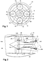
- the figure 1 schematically illustrates the structure of a reducer with epicyclic or planetary configuration.
- This type of reduction gear 10 conventionally comprises an internal sun gear 12 (also called central or sun gear) and an external sun gear 14, the two sun gears being coaxial.
- the internal sun gear 12 can be rotatable around its axis X, the external sun gear 14 possibly being fixed, or coupled in rotation to a propeller as in the case of a turboprop or to a fan wheel as in the case of a turbofan engine.
- the reduction gear 10 further comprises satellites, or satellite pinions 16 mounted so as to be able to rotate on pivots 18 of a planet carrier 20. Each satellite 16 meshes simultaneously with the internal sun gear 12 and with the external sun gear 14.
- -satellites 20 is fixed or pivoting around the axis X of the internal sun gear 12 and the external sun gear 14.
- the input can be formed by the internal sun gear 12, and the output formed by the planet carrier 20.
- the planet carrier 20 can be fixed or rotatably coupled to a propeller of a turboprop or to a fan wheel of a turbofan engine.
- the picture 2 schematically illustrates a turbomachine 22 comprising, from upstream to downstream, a fan 24, a low pressure compressor 28a and a high pressure compressor 28b, a combustion chamber 29, a high pressure turbine 26a and a low pressure turbine 26b.
- the rotor of the high pressure turbine drives the rotor of the high pressure compressor and the rotor of the low pressure turbine drives the rotor of the low pressure compressor which is connected to the fan.
- a reducer 10 is interposed between the fan rotor and the rotor of the low pressure compressor to reduce the speed of rotation of the fan 24, depending on the rotational speed of the low pressure turbine rotor.
- the internal central or planetary pinion 12 surrounds and is then integral in rotation with the shaft 32 of the low pressure compressor 28 as illustrated for example by the figures 1 and 2 .
- the reducer 10 can in particular be mounted in an annular enclosure formed radially inside a low pressure compressor 28a arranged downstream of the fan wheel 24 and upstream of a high pressure compressor 28b as visible on the picture 2 .
- the picture 3 illustrates in perspective the reducer 10 detailed above, the outer sun gear not being shown. We therefore distinguish the planet carrier 20 carrying the planet wheels 16, as well as the teeth of the planet wheels 16a and 16b.
- the outer sun gear 14 comprises a first crown 14a and a second crown 14b.
- the satellites 16 each comprise a first toothing 16a and a second toothing 16b which are spaced axially along the longitudinal axis X.
- the first toothings 16a of the satellites 16 mesh with a first toothing 34 of the first ring gear 14a of the outer sun gear 14 and the second toothings 16b of the planet wheels 16 mesh with a second toothing 36 of the second ring gear 14b.
- first toothing 34 of the first crown 14a and the second toothing 36 of the second crown 14a are inclined with respect to the longitudinal axis X of the reducer 10. More specifically, the first 34 and second 36 toothings of the crowns 14a, 14b are here inclined according to a herringbone configuration, which makes it possible to increase the surface in contact between the toothings 16a, 16b of the satellites 16 and the toothings 34, 36 of the crowns 14a, 14b. To obtain such an assembly, it is easily understood that the first crown 14a and the second crown 14b must be mounted along the longitudinal axis X and in opposite directions.
- first crown 14a comprises a radial annular flange 38 intended to be applied and fixed, by bolting for example, on a second radial annular flange 40 of the second crown 14b.
- the connection of these two flanges 38, 40 annular radial can also be used to fix one or more other flanges, for fixing together for example the crown holder 41 with said flanges 38, 40 annular radial.
- the assembly of the first crown 14a and of the second crown 14b is carried out for example by centering the second crown 14b on the first crown 14a.
- this assembly leads to overloading of one of the first 16a and second 16b toothings of the satellites 16, which is not desirable.
- the figures 5a, 5b , 6a and 6b represent an installation 42 according to this document, the installation comprising a frame 44 forming means for supporting the reducer and comprising a first support member 46, a second support member 48 and a third support member 50 carried by a base 52 of the frame 44.
- the first member 46 and the second member 48 make it possible to maintain the planet carrier in position.
- these members 46, 48, 50 comprise a tubular body 51 extending along the longitudinal axis X of the reducer.
- the first member 46 and the second member 48 each comprise an opening for receiving the tubular body 51 connected to the planet carrier.
- the third support member 50 comprises an arm 55 extending along the longitudinal axis X of the reducer 10 when the latter is supported by the frame 44.
- the first support member 46 comprises an opening whose internal periphery comprises means of locking in rotation such as axial splines for example, cooperating with splines 53 of the tubular body 51.
- the arm 55 comprises a device for fixing with the internal sun gear 12, for example via splines 54 cooperating with splines of the radially internal face of the internal sun gear 12.
- the internal sun gear 12, the satellites and the planet carrier are locked in rotation about the axis X on the arm 55.
- the splines of the radially internal face of the sun gear 12 internal are pre-existing and allow rotational coupling of the internal sun gear 12 with the shaft 32 of the compressor.
- a nut can be screwed onto the free end of arm 55 and tightened through the end of the planet carrier.
- the frame 44 further comprises a gantry 56 shown only on the figures 6a and 6b and carried by the base 52.
- This gantry 56 has a substantially rectangular shape formed by two first vertical uprights 58a, 58b and two second horizontal uprights 60a, 60b.
- the horizontal upright 60b could be confused with the base 52.
- the gantry 56 carries a first ring 62 and a second ring 64 spaced axially from each other and each having an axis substantially aligned with the longitudinal axis X of the reduction gear without however being purely coaxial therewith.
- the first ring 62 is connected to first means for applying a torque 66 to the first ring 62 carried by the gantry 56 via first connection means 68 allowing a degree of freedom of the first ring 62 in rotation around the longitudinal X axis.
- the second ring 64 is connected to the gantry 56 to second means for applying a torque 70 to the second ring 64 via second connecting means 72 allowing a degree of freedom of the second ring 64 in rotation around the longitudinal X axis.
- the first connecting means 68 and the second connecting means 72 are independent of each other, which makes it possible to independently connect the first ring 62 and the second ring 64 to the gantry 56.
- the first torque application means 66 comprise a first traction member 74 and a second traction member 76 carried by the gantry 56 of the frame 44.
- the first traction member 74 is carried by a horizontal upright 60a of the gantry 56 and the second traction member 76 is carried by the horizontal upright 60b opposite the gantry 56.
- the second means for applying a torque 70 comprise a third traction member 78 and a fourth member 80 of traction carried by the gantry 56 of the frame 44.
- the third member 78 of traction is carried by a vertical upright 58a of the gantry 56 and the fourth member 80 of traction is carried by the vertical upright 58b opposite of the gantry 56.
- the traction members 74, 76, 78, 80 are cylinders each comprising a cylinder body 74a, 76a, 78a, 80a and a rod 74b, 76b, 78b, 80b mounted in translation in the cylinder body 74a, 76a, 78a, 80a.
- a connecting rod 82, 84, 86, 88 connects one end of each cylinder rod 74a, 76a, 78a, 80a to the periphery of a ring 62, 64. More specifically, the first traction member 74 is connected by a first link 86 to the first ring 62 and the second traction member 76 is connected by a second link 82 to the first ring 62. The third traction member 78 is connected by a third link 80 to the second ring 64 and the fourth traction member 80 is connected by a fourth connecting rod 88 to the second ring 64.
- each connecting rod 82, 84, 86, 88 is articulated in rotation at one end on a ring 62, 64 and at its opposite end on the rod 74b, 76b, 78b, 80b of the cylinder. More particularly, it is observed that the first link 82 and the second link 86, which are connected to the first ring 62 are oriented substantially parallel and extend in opposite directions from a first direction 90 substantially perpendicular to the longitudinal axis X and from opposite ends of a diameter of the first ring 62.
- the third link 84 and the fourth link 88, which are connected to the second ring 64 are oriented substantially parallel and extend in opposite directions from a second direction 92 substantially perpendicular to the longitudinal axis X and from opposite ends of a diameter of the second ring 64. It is noted that the first direction 90 is perpendicular to the second direction 92, which in particular saves space for mounting the torque application means on the gantry.
- the first ring 62 comprises first means for coupling in rotation with the first crown 14a, these first coupling means cooperating with complementary means carried by the first crown.
- the second ring 64 comprises second means for coupling in rotation with the second crown 14b, these second coupling means cooperating with complementary means carried by the second crown 14b.
- the first coupling means of the first ring 62 and the second coupling means of the second ring 64 are grooves 94 which cooperate with grooves 96 of the radially outer surfaces of the first crown 14a and of the second crown 14b.
- the assembly formed by the internal sun gear 12, the planet pinions 16 and the planet carrier 20 is mounted on the frame 44 in the position indicated as shown and described in figures 5a and 5b .
- the first crown 14a is mounted around the satellites 16 so that the first toothing 34 of the first crown 14a comes into engagement with the first toothings 16a of the satellites 16.
- the second crown 14b is mounted around satellites 16 so that second toothing 36 of second crown 14b engages with second toothing 16b of satellites 16.
- first ring 62 is mounted in engagement with the periphery radially outer of the first flange 38 and the second ring 64 is mounted in engagement with the periphery radially external of the second flange 40.
- a first torque is applied simultaneously and independently to the first ring 62 centered on the axis of the first crown 14a and a second torque to the second crown 14b centered on the axis of the second crown 14b, the first pair and the second pair having identical values.
- the first torque and the second torque are applied in the same direction of rotation around the axes of the first and second crowns.
- the application of the torques independently to each of the first ring 62 and of the second ring 64 is made possible by the use of rod connection means as described above.
- the first 38 and second 40 flanges are clamped together, by bolting 96 into the orifices of the first and second flanges.
- the gripping of the first ring 62 with the flange 38 of the first ring 14a, and of the second ring 64 with the flange 40 of the second ring 14b can be achieved by systems other than radial grips. external, such as by tie rods passing through the screw holes of flanges 38 and 40.
- the torque applied to a value which corresponds to the torque undergone by the reduction gear during a given phase of use this torque being for example greater than 10 N. It is understood that the torque must be not bad.
Landscapes
- Engineering & Computer Science (AREA)
- General Engineering & Computer Science (AREA)
- Mechanical Engineering (AREA)
- Retarders (AREA)
Claims (14)
- Verfahren zur Montage eines Untersetzungsgetriebes (10) mit einer Längsachse X, enthaltend ein äußeres Sonnenrad (14) und Planetenräder (16), die mit einem inneren Sonnenrad (12) und mit dem äußeren Sonnenrad (14) in Eingriff stehen und jeweils frei drehbar auf einem Planetenträger (20) gelagert sind, wobei das äußere Sonnenrad (14) ein erstes Hohlrad (14a) mit einer ersten Verzahnung (34) und ein zweites Hohlrad (14b) mit einer zweiten Verzahnung (36) umfasst, die jeweils mit ersten (16a) und zweiten (16b) Verzahnungen der Planetenräder (16) in Eingriff stehen, wobei das Verfahren die folgenden Schritte umfasst:a) Bereitstellen einer Anordnung, die das innere Sonnenrad (12) und die Planetenräder (16), die mit dem inneren Sonnenrad (12) in Eingriff stehen und von dem Planetenträger (20) getragen werden, umfasst,b) Montieren des ersten Hohlrads (14a) und des zweiten Hohlrads (14b) um die Planetenräder (16) herum, so dass die Verzahnungen (34, 36) des ersten Hohlrads (14a) und des zweiten Hohlrads (14b) jeweils mit den ersten Verzahnungen (16a) der Planetenräder bzw. den zweiten Verzahnungen der Planetenräder (16b) in Eingriff gelangen, gekennzeichnet durch den nachstehenden Schritt:c) Aufbringen eines auf die Achse des ersten Hohlrads (14a) zentrierten ersten Drehmoments auf das erste Hohlrad (14a) und eines auf die Achse des zweiten Hohlrads (14b) zentrierten zweiten Drehmoments auf das zweite Hohlrad (14b), wobei das erste Drehmoment und das zweite Drehmoment identische Werte haben und in derselben Drehrichtung um die Achsen des ersten und des zweiten Hohlrads (14a, 14b) aufgebracht werden.
- Verfahren nach Anspruch 1, wobei es nach Schritt c) einen Schritt des festen Verbindens von dem ersten Hohlrad (14a) und dem zweiten Hohlrad (14b) umfasst.
- Verfahren nach Anspruch 2, wobei der Schritt des festen Verbindens durch Verschrauben eines ersten ringförmigen Flansches (38) des ersten Hohlrads (14a) mit einem zweiten ringförmigen Flansch (40) des zweiten Hohlrads (14b) erfolgt.
- Verfahren nach einem der Ansprüche 1 bis 3, wobei das aufgebrachte Drehmoment einen Wert hat, der dem Drehmoment entspricht, das das Untersetzungsgetriebe (10) in einer vorgegebenen Nutzungsphase erfährt, wobei dieses Drehmoment zumindest größer als 10 N ist.
- Verfahren nach einem der Ansprüche 1 bis 4, wobei die ersten (16a) und die zweiten (16b) Verzahnungen der Planetenräder (16), die erste Verzahnung (34) des ersten Hohlrads (14a) und die zweite Verzahnung (36) des zweiten Hohlrads (14b) in Bezug auf die Längsachse (X) des Untersetzungsgetriebes (10) geneigt verlaufen.
- Verfahren nach Anspruch 5, wobei die erste Verzahnung (34) des ersten Hohlrads (14a) und die zweite Verzahnung (36) des zweiten Hohlrads (14b) eine Fischgrät-Anordnung aufweisen, die mit einer Fischgrät-Anordnung zusammenwirkt, die aus den ersten (16a) und den zweiten (16b) Verzahnungen der Planetenräder (16) gebildet ist.
- Verfahren nach einem der Ansprüche 1 bis 6, wobei es zwischen den Schritten a) und b) einen Zwischenschritt umfasst, der darin besteht, das innere Sonnenrad, die Planetenräder und den Planetenträger gegen eine Drehung um die Längsachse X zu sichern.
- Anlage zum Durchführen des Verfahrens zur Montage eines äußeren Sonnenrads (14) mit doppeltem Hohlrad (14a, 14b) in ein Untersetzungsgetriebe (10) nach Anspruch 1, enthaltend:- ein Gestell (44) zum Tragen des Untersetzungsgetriebezuges (10) entlang seiner Längsachse,- erste Mittel (66) zum Aufbringen eines Drehmoments um die Achse eines ersten Rings (62), der geeignet ist, mit einem ersten Hohlrad (14a) des äußeren Sonnenrads (14) in Eingriff zu gelangen,- zweite Mittel (70) zum Aufbringen eines Drehmoments um die Achse eines zweiten Rings (64), der geeignet ist, mit einem zweiten Hohlrad (14b) des äußeren Sonnenrads (14) in Eingriff zu gelangen,- wobei der erste Ring (62) mit den ersten Mitteln (66) zum Aufbringen eines Drehmoments über erste Verbindungsmittel (68) verbunden ist, die einen Freiheitsgrad des ersten Rings (62) in einer Ebene senkrecht zur Längsachse zulassen, und wobei der zweite Ring (64) mit den zweiten Mitteln (70) zum Aufbringen eines Drehmoments über zweite Verbindungsmittel (72) verbunden ist, die einen Freiheitsgrad des ersten Rings (62) in einer Ebene senkrecht zur Längsachse zulassen, wobei die ersten Verbindungsmittel (68) von den zweiten Verbindungsmitteln (72) unabhängig sind.
- Anlage nach Anspruch 8, wobei:- die ersten Mittel (66) zum Aufbringen eines Drehmoments N Zugorgane (74, 76) umfassen, die von dem Gestell getragen werden und gleichmäßig um die Achse des ersten Rings (62) verteilt sind,- die zweiten Mittel (70) zum Aufbringen eines Drehmoments N Zugorgane (78, 80) umfassen, die von dem Gestell getragen werden und gleichmäßig um die Achse des ersten Rings (64) verteilt sind.
- Anlage nach Anspruch 8 oder 9, wobei die ersten Mittel (66) zum Aufbringen eines Drehmoments zumindest ein erstes Zugorgan (74) und zumindest ein zweites Zugorgan (76) umfassen, die von dem Gestell (44) getragen werden und dazu ausgelegt sind, eine Zugkraft an zwei diametral gegenüberliegenden Punkten des ersten Rings (62) und in entgegengesetzten Richtungen auszuüben, wobei die zweiten Mittel (70) zum Aufbringen eines Drehmoments zumindest ein drittes Zugorgan (78) und zumindest ein viertes Zugorgan (80) umfassen, die von dem Gestell (44) getragen werden und dazu ausgelegt sind, eine Zugkraft an zwei diametral gegenüberliegenden Punkten des zweiten Rings (64) und in entgegengesetzten Richtungen auszuüben.
- Anlage nach Anspruch 9, wobei jedes Zugorgan mit dem Ring, dem es zugeordnet ist, über eine Verbindungsstange verbunden ist, die an einem Ende drehbar an dem betreffenden Ring (62, 64) und am entgegengesetzten Ende drehbar an einem beweglichen Teil des Zugorgans angelenkt ist.
- Anlage nach Anspruch 9 oder 11, wobei die Zugorgane (74, 76, 78, 80) Kraftzylinder sind.
- Anlage nach einem der Ansprüche 8 bis 11, wobei der erste Ring (62) und der zweite Ring (64) auf ihren Innenseiten axiale Rillen aufweisen, die geeignet sind, mit entsprechenden axialen Rillen zusammenzuwirken, die auf radial äußeren Seiten von ringförmigen Flanschen des ersten und des zweiten Hohlrads ausgebildet sind.
- Anlage nach einem der Ansprüche 8 bis 13, wobei das Gestell Mittel zur Drehsicherung des Untersetzungsgetriebes, des inneren Sonnenrads und des Planetenträgers um die Längsachse X umfasst.
Applications Claiming Priority (2)
| Application Number | Priority Date | Filing Date | Title |
|---|---|---|---|
| FR1854873A FR3081959B1 (fr) | 2018-06-05 | 2018-06-05 | Procede d'assemblage d'un reducteur et installation de mise en oeuvre du procede |
| PCT/FR2019/051346 WO2019234357A1 (fr) | 2018-06-05 | 2019-06-05 | Procede d'assemblage d'un reducteur et installation de mise en œuvre du procede |
Publications (2)
| Publication Number | Publication Date |
|---|---|
| EP3803159A1 EP3803159A1 (de) | 2021-04-14 |
| EP3803159B1 true EP3803159B1 (de) | 2022-03-30 |
Family
ID=63722512
Family Applications (1)
| Application Number | Title | Priority Date | Filing Date |
|---|---|---|---|
| EP19735614.0A Active EP3803159B1 (de) | 2018-06-05 | 2019-06-05 | Verfahren zum zusammenbau eines untersetzungsgetriebes und anlage zur durchführung des verfahrens |
Country Status (5)
| Country | Link |
|---|---|
| US (1) | US11499623B2 (de) |
| EP (1) | EP3803159B1 (de) |
| CN (1) | CN112313433B (de) |
| FR (1) | FR3081959B1 (de) |
| WO (1) | WO2019234357A1 (de) |
Families Citing this family (2)
| Publication number | Priority date | Publication date | Assignee | Title |
|---|---|---|---|---|
| US12104541B1 (en) | 2023-05-09 | 2024-10-01 | Pratt & Whitney Canada Corp. | Method and system for assembling a reduction gearbox |
| FR3165706A1 (fr) * | 2024-08-20 | 2026-02-27 | Safran Transmission Systems | Couronne dentee de reducteur pour turbomachine d’aeronef, reducteur dote d’une telle couronne dentee et turbomachine d’aeronef equipe d’un tel reducteur |
Family Cites Families (12)
| Publication number | Priority date | Publication date | Assignee | Title |
|---|---|---|---|---|
| DE4304657A1 (de) * | 1992-05-18 | 1993-11-25 | Zahnradfabrik Friedrichshafen | Planetengetriebe in doppelt schrägverzahnter Bauweise |
| US6117036A (en) * | 1999-07-29 | 2000-09-12 | New Venture Gear, Inc. | Split helical planetary gear assembly |
| GB0326933D0 (en) * | 2003-11-19 | 2003-12-24 | Hansen Transmissions Int | Gear transmission unit with planet carrier |
| FR2938032A1 (fr) * | 2008-11-03 | 2010-05-07 | Somfy Sas | Actionneur pour ecran domotique et installation de fermeture ou de protection solaire comprenant un tel actionneur. |
| IT1397667B1 (it) * | 2009-12-22 | 2013-01-18 | Avio Spa | Rotismo. |
| US20150111685A1 (en) * | 2012-05-25 | 2015-04-23 | Schaeffler Technologies Gmbh & Co. Kg | Combined friction bearing in a planetary drive |
| FR3011901B1 (fr) * | 2013-10-10 | 2017-02-10 | Hispano-Suiza | Porte-satellites pour un reducteur de vitesse a train epicycloidal |
| FR3016189B1 (fr) * | 2014-01-07 | 2018-09-28 | Safran Aircraft Engines | Dispositif de reduction epicycloidal pour l'entrainement en rotation des ensembles de pales d'une turbomachine a reducteur |
| FR3035375B1 (fr) * | 2015-04-23 | 2018-07-27 | Safran Aircraft Engines | Reducteur a train d'engrenages epicycloidal pour une turbomachine. |
| WO2019123772A1 (ja) * | 2017-12-18 | 2019-06-27 | ソニー株式会社 | アクチュエータ |
| FR3092885B1 (fr) * | 2019-02-20 | 2021-09-24 | Safran Trans Systems | Solaire pour un reducteur mecanique de turbomachine d’aeronef |
| FR3111390B1 (fr) * | 2020-06-11 | 2022-05-13 | Safran Trans Systems | Reducteur mecanique de turbomachine d’aeronef |
-
2018
- 2018-06-05 FR FR1854873A patent/FR3081959B1/fr active Active
-
2019
- 2019-06-05 CN CN201980043207.8A patent/CN112313433B/zh active Active
- 2019-06-05 EP EP19735614.0A patent/EP3803159B1/de active Active
- 2019-06-05 WO PCT/FR2019/051346 patent/WO2019234357A1/fr not_active Ceased
- 2019-06-05 US US16/972,694 patent/US11499623B2/en active Active
Also Published As
| Publication number | Publication date |
|---|---|
| CN112313433B (zh) | 2023-12-29 |
| FR3081959A1 (fr) | 2019-12-06 |
| EP3803159A1 (de) | 2021-04-14 |
| US20210254702A1 (en) | 2021-08-19 |
| US11499623B2 (en) | 2022-11-15 |
| CN112313433A (zh) | 2021-02-02 |
| FR3081959B1 (fr) | 2020-07-17 |
| WO2019234357A1 (fr) | 2019-12-12 |
Similar Documents
| Publication | Publication Date | Title |
|---|---|---|
| EP3055589B1 (de) | Planetenträger für ein epizyklisches untersetzungsgetriebe | |
| CA2917228C (fr) | Integration d'un train d'engrenages dans un voile de pignon de boitier d'entrainement pour turbomachine | |
| EP3922886A1 (de) | Mechanisches reduktionsgetriebe für turbotriebwerk eines luftfahrzeugs | |
| EP3922831B1 (de) | Mechanisches reduktionsgetriebe für turbotriebwerk eines luftfahrzeugs | |
| EP3649378B1 (de) | Zahnkranz für ein epizyklisches- oder planetenuntersetzungsgetriebe einer turbomaschine | |
| EP4303468B1 (de) | Sonnenrad für ein reduktionsgetriebe eines turbotriebwerks eines luftfahrzeugs | |
| EP3763932B1 (de) | Mechanisches reduktionsgetriebe für turbotriebwerk eines luftfahrzeugs | |
| FR3042009A1 (fr) | Turbo moteur a soufflantes deportees avec un systeme differentiel | |
| EP3803159B1 (de) | Verfahren zum zusammenbau eines untersetzungsgetriebes und anlage zur durchführung des verfahrens | |
| EP3561267B1 (de) | Verfahren zum zusammenbau eines getriebes | |
| FR2975149A1 (fr) | Systeme pour fixer deux pieces tubulaires l'une dans l'autre portant un palier a roulement | |
| EP3997317B1 (de) | Anordnung zum halten eines getriebezugs in einer turbomaschine | |
| EP3561266B1 (de) | Verfahren zum zusammenbau eines epizykloidal oder planeten-getriebes | |
| EP4339099B1 (de) | Untersetzungsgetriebe für eine antriebsvorrichtung eines rades eines flugzeugfahrwerks | |
| EP4339097B1 (de) | Vorrichtung zum antrieb mindestens eines rades eines flugzeugfahrwerks | |
| EP3682138B1 (de) | Drehzapfen für ein gleitlager | |
| EP4339098B1 (de) | Antriebsvorrichtung für mindestens ein rad eines flugzeugfahrwerks | |
| WO2025109268A1 (fr) | Dispositif d'entrainement d'au moins une roue d'un train d'atterrissage d'aeronef | |
| EP3721118B1 (de) | Planetengetriebe | |
| WO2025168901A1 (fr) | Réducteur | |
| WO2025022052A1 (fr) | Reducteur mecanique pour une turbomachine | |
| WO2025109266A1 (fr) | Motoreducteur pour un aeronef | |
| WO2025109264A1 (fr) | Motoreducteur pour un aeronef | |
| WO2025133526A1 (fr) | Reducteur mecanique pour une turbomachine d'aeronef | |
| WO2026057941A1 (fr) | Dispositif de liaison entre des elements, notamment des elements rotatifs d'une turbomachine d'aeronef, reducteur et turbomachine equipes d'un tel dispositif |
Legal Events
| Date | Code | Title | Description |
|---|---|---|---|
| STAA | Information on the status of an ep patent application or granted ep patent |
Free format text: STATUS: UNKNOWN |
|
| STAA | Information on the status of an ep patent application or granted ep patent |
Free format text: STATUS: THE INTERNATIONAL PUBLICATION HAS BEEN MADE |
|
| PUAI | Public reference made under article 153(3) epc to a published international application that has entered the european phase |
Free format text: ORIGINAL CODE: 0009012 |
|
| STAA | Information on the status of an ep patent application or granted ep patent |
Free format text: STATUS: REQUEST FOR EXAMINATION WAS MADE |
|
| 17P | Request for examination filed |
Effective date: 20210104 |
|
| AK | Designated contracting states |
Kind code of ref document: A1 Designated state(s): AL AT BE BG CH CY CZ DE DK EE ES FI FR GB GR HR HU IE IS IT LI LT LU LV MC MK MT NL NO PL PT RO RS SE SI SK SM TR |
|
| AX | Request for extension of the european patent |
Extension state: BA ME |
|
| DAV | Request for validation of the european patent (deleted) | ||
| DAX | Request for extension of the european patent (deleted) | ||
| GRAP | Despatch of communication of intention to grant a patent |
Free format text: ORIGINAL CODE: EPIDOSNIGR1 |
|
| STAA | Information on the status of an ep patent application or granted ep patent |
Free format text: STATUS: GRANT OF PATENT IS INTENDED |
|
| INTG | Intention to grant announced |
Effective date: 20211021 |
|
| GRAS | Grant fee paid |
Free format text: ORIGINAL CODE: EPIDOSNIGR3 |
|
| GRAA | (expected) grant |
Free format text: ORIGINAL CODE: 0009210 |
|
| STAA | Information on the status of an ep patent application or granted ep patent |
Free format text: STATUS: THE PATENT HAS BEEN GRANTED |
|
| AK | Designated contracting states |
Kind code of ref document: B1 Designated state(s): AL AT BE BG CH CY CZ DE DK EE ES FI FR GB GR HR HU IE IS IT LI LT LU LV MC MK MT NL NO PL PT RO RS SE SI SK SM TR |
|
| REG | Reference to a national code |
Ref country code: GB Ref legal event code: FG4D Free format text: NOT ENGLISH |
|
| REG | Reference to a national code |
Ref country code: CH Ref legal event code: EP |
|
| REG | Reference to a national code |
Ref country code: AT Ref legal event code: REF Ref document number: 1479477 Country of ref document: AT Kind code of ref document: T Effective date: 20220415 |
|
| REG | Reference to a national code |
Ref country code: DE Ref legal event code: R096 Ref document number: 602019013154 Country of ref document: DE |
|
| REG | Reference to a national code |
Ref country code: IE Ref legal event code: FG4D Free format text: LANGUAGE OF EP DOCUMENT: FRENCH |
|
| REG | Reference to a national code |
Ref country code: LT Ref legal event code: MG9D |
|
| PG25 | Lapsed in a contracting state [announced via postgrant information from national office to epo] |
Ref country code: SE Free format text: LAPSE BECAUSE OF FAILURE TO SUBMIT A TRANSLATION OF THE DESCRIPTION OR TO PAY THE FEE WITHIN THE PRESCRIBED TIME-LIMIT Effective date: 20220330 Ref country code: RS Free format text: LAPSE BECAUSE OF FAILURE TO SUBMIT A TRANSLATION OF THE DESCRIPTION OR TO PAY THE FEE WITHIN THE PRESCRIBED TIME-LIMIT Effective date: 20220330 Ref country code: NO Free format text: LAPSE BECAUSE OF FAILURE TO SUBMIT A TRANSLATION OF THE DESCRIPTION OR TO PAY THE FEE WITHIN THE PRESCRIBED TIME-LIMIT Effective date: 20220630 Ref country code: LT Free format text: LAPSE BECAUSE OF FAILURE TO SUBMIT A TRANSLATION OF THE DESCRIPTION OR TO PAY THE FEE WITHIN THE PRESCRIBED TIME-LIMIT Effective date: 20220330 Ref country code: HR Free format text: LAPSE BECAUSE OF FAILURE TO SUBMIT A TRANSLATION OF THE DESCRIPTION OR TO PAY THE FEE WITHIN THE PRESCRIBED TIME-LIMIT Effective date: 20220330 Ref country code: BG Free format text: LAPSE BECAUSE OF FAILURE TO SUBMIT A TRANSLATION OF THE DESCRIPTION OR TO PAY THE FEE WITHIN THE PRESCRIBED TIME-LIMIT Effective date: 20220630 |
|
| REG | Reference to a national code |
Ref country code: NL Ref legal event code: MP Effective date: 20220330 |
|
| REG | Reference to a national code |
Ref country code: AT Ref legal event code: MK05 Ref document number: 1479477 Country of ref document: AT Kind code of ref document: T Effective date: 20220330 |
|
| PG25 | Lapsed in a contracting state [announced via postgrant information from national office to epo] |
Ref country code: LV Free format text: LAPSE BECAUSE OF FAILURE TO SUBMIT A TRANSLATION OF THE DESCRIPTION OR TO PAY THE FEE WITHIN THE PRESCRIBED TIME-LIMIT Effective date: 20220330 Ref country code: GR Free format text: LAPSE BECAUSE OF FAILURE TO SUBMIT A TRANSLATION OF THE DESCRIPTION OR TO PAY THE FEE WITHIN THE PRESCRIBED TIME-LIMIT Effective date: 20220701 Ref country code: FI Free format text: LAPSE BECAUSE OF FAILURE TO SUBMIT A TRANSLATION OF THE DESCRIPTION OR TO PAY THE FEE WITHIN THE PRESCRIBED TIME-LIMIT Effective date: 20220330 |
|
| PG25 | Lapsed in a contracting state [announced via postgrant information from national office to epo] |
Ref country code: NL Free format text: LAPSE BECAUSE OF FAILURE TO SUBMIT A TRANSLATION OF THE DESCRIPTION OR TO PAY THE FEE WITHIN THE PRESCRIBED TIME-LIMIT Effective date: 20220330 |
|
| PG25 | Lapsed in a contracting state [announced via postgrant information from national office to epo] |
Ref country code: SM Free format text: LAPSE BECAUSE OF FAILURE TO SUBMIT A TRANSLATION OF THE DESCRIPTION OR TO PAY THE FEE WITHIN THE PRESCRIBED TIME-LIMIT Effective date: 20220330 Ref country code: SK Free format text: LAPSE BECAUSE OF FAILURE TO SUBMIT A TRANSLATION OF THE DESCRIPTION OR TO PAY THE FEE WITHIN THE PRESCRIBED TIME-LIMIT Effective date: 20220330 Ref country code: RO Free format text: LAPSE BECAUSE OF FAILURE TO SUBMIT A TRANSLATION OF THE DESCRIPTION OR TO PAY THE FEE WITHIN THE PRESCRIBED TIME-LIMIT Effective date: 20220330 Ref country code: PT Free format text: LAPSE BECAUSE OF FAILURE TO SUBMIT A TRANSLATION OF THE DESCRIPTION OR TO PAY THE FEE WITHIN THE PRESCRIBED TIME-LIMIT Effective date: 20220801 Ref country code: ES Free format text: LAPSE BECAUSE OF FAILURE TO SUBMIT A TRANSLATION OF THE DESCRIPTION OR TO PAY THE FEE WITHIN THE PRESCRIBED TIME-LIMIT Effective date: 20220330 Ref country code: EE Free format text: LAPSE BECAUSE OF FAILURE TO SUBMIT A TRANSLATION OF THE DESCRIPTION OR TO PAY THE FEE WITHIN THE PRESCRIBED TIME-LIMIT Effective date: 20220330 Ref country code: CZ Free format text: LAPSE BECAUSE OF FAILURE TO SUBMIT A TRANSLATION OF THE DESCRIPTION OR TO PAY THE FEE WITHIN THE PRESCRIBED TIME-LIMIT Effective date: 20220330 Ref country code: AT Free format text: LAPSE BECAUSE OF FAILURE TO SUBMIT A TRANSLATION OF THE DESCRIPTION OR TO PAY THE FEE WITHIN THE PRESCRIBED TIME-LIMIT Effective date: 20220330 |
|
| PG25 | Lapsed in a contracting state [announced via postgrant information from national office to epo] |
Ref country code: PL Free format text: LAPSE BECAUSE OF FAILURE TO SUBMIT A TRANSLATION OF THE DESCRIPTION OR TO PAY THE FEE WITHIN THE PRESCRIBED TIME-LIMIT Effective date: 20220330 Ref country code: IS Free format text: LAPSE BECAUSE OF FAILURE TO SUBMIT A TRANSLATION OF THE DESCRIPTION OR TO PAY THE FEE WITHIN THE PRESCRIBED TIME-LIMIT Effective date: 20220730 Ref country code: AL Free format text: LAPSE BECAUSE OF FAILURE TO SUBMIT A TRANSLATION OF THE DESCRIPTION OR TO PAY THE FEE WITHIN THE PRESCRIBED TIME-LIMIT Effective date: 20220330 |
|
| REG | Reference to a national code |
Ref country code: DE Ref legal event code: R097 Ref document number: 602019013154 Country of ref document: DE |
|
| PG25 | Lapsed in a contracting state [announced via postgrant information from national office to epo] |
Ref country code: MC Free format text: LAPSE BECAUSE OF FAILURE TO SUBMIT A TRANSLATION OF THE DESCRIPTION OR TO PAY THE FEE WITHIN THE PRESCRIBED TIME-LIMIT Effective date: 20220330 Ref country code: DK Free format text: LAPSE BECAUSE OF FAILURE TO SUBMIT A TRANSLATION OF THE DESCRIPTION OR TO PAY THE FEE WITHIN THE PRESCRIBED TIME-LIMIT Effective date: 20220330 |
|
| REG | Reference to a national code |
Ref country code: CH Ref legal event code: PL |
|
| PLBE | No opposition filed within time limit |
Free format text: ORIGINAL CODE: 0009261 |
|
| STAA | Information on the status of an ep patent application or granted ep patent |
Free format text: STATUS: NO OPPOSITION FILED WITHIN TIME LIMIT |
|
| REG | Reference to a national code |
Ref country code: BE Ref legal event code: MM Effective date: 20220630 |
|
| 26N | No opposition filed |
Effective date: 20230103 |
|
| PG25 | Lapsed in a contracting state [announced via postgrant information from national office to epo] |
Ref country code: LU Free format text: LAPSE BECAUSE OF NON-PAYMENT OF DUE FEES Effective date: 20220605 Ref country code: LI Free format text: LAPSE BECAUSE OF NON-PAYMENT OF DUE FEES Effective date: 20220630 Ref country code: IE Free format text: LAPSE BECAUSE OF NON-PAYMENT OF DUE FEES Effective date: 20220605 Ref country code: CH Free format text: LAPSE BECAUSE OF NON-PAYMENT OF DUE FEES Effective date: 20220630 |
|
| PG25 | Lapsed in a contracting state [announced via postgrant information from national office to epo] |
Ref country code: SI Free format text: LAPSE BECAUSE OF FAILURE TO SUBMIT A TRANSLATION OF THE DESCRIPTION OR TO PAY THE FEE WITHIN THE PRESCRIBED TIME-LIMIT Effective date: 20220330 Ref country code: BE Free format text: LAPSE BECAUSE OF NON-PAYMENT OF DUE FEES Effective date: 20220630 |
|
| PG25 | Lapsed in a contracting state [announced via postgrant information from national office to epo] |
Ref country code: IT Free format text: LAPSE BECAUSE OF FAILURE TO SUBMIT A TRANSLATION OF THE DESCRIPTION OR TO PAY THE FEE WITHIN THE PRESCRIBED TIME-LIMIT Effective date: 20220330 |
|
| PG25 | Lapsed in a contracting state [announced via postgrant information from national office to epo] |
Ref country code: MK Free format text: LAPSE BECAUSE OF FAILURE TO SUBMIT A TRANSLATION OF THE DESCRIPTION OR TO PAY THE FEE WITHIN THE PRESCRIBED TIME-LIMIT Effective date: 20220330 Ref country code: CY Free format text: LAPSE BECAUSE OF FAILURE TO SUBMIT A TRANSLATION OF THE DESCRIPTION OR TO PAY THE FEE WITHIN THE PRESCRIBED TIME-LIMIT Effective date: 20220330 |
|
| PG25 | Lapsed in a contracting state [announced via postgrant information from national office to epo] |
Ref country code: HU Free format text: LAPSE BECAUSE OF FAILURE TO SUBMIT A TRANSLATION OF THE DESCRIPTION OR TO PAY THE FEE WITHIN THE PRESCRIBED TIME-LIMIT; INVALID AB INITIO Effective date: 20190605 |
|
| PG25 | Lapsed in a contracting state [announced via postgrant information from national office to epo] |
Ref country code: MT Free format text: LAPSE BECAUSE OF FAILURE TO SUBMIT A TRANSLATION OF THE DESCRIPTION OR TO PAY THE FEE WITHIN THE PRESCRIBED TIME-LIMIT Effective date: 20220330 |
|
| PGFP | Annual fee paid to national office [announced via postgrant information from national office to epo] |
Ref country code: DE Payment date: 20250618 Year of fee payment: 7 |
|
| PGFP | Annual fee paid to national office [announced via postgrant information from national office to epo] |
Ref country code: GB Payment date: 20250625 Year of fee payment: 7 |
|
| PGFP | Annual fee paid to national office [announced via postgrant information from national office to epo] |
Ref country code: FR Payment date: 20250623 Year of fee payment: 7 |
|
| PG25 | Lapsed in a contracting state [announced via postgrant information from national office to epo] |
Ref country code: TR Free format text: LAPSE BECAUSE OF FAILURE TO SUBMIT A TRANSLATION OF THE DESCRIPTION OR TO PAY THE FEE WITHIN THE PRESCRIBED TIME-LIMIT Effective date: 20220330 |