EP3803165B1 - Joint mécanique avec une face d'étanchéité dotée de canaux - Google Patents
Joint mécanique avec une face d'étanchéité dotée de canaux Download PDFInfo
- Publication number
- EP3803165B1 EP3803165B1 EP19815144.1A EP19815144A EP3803165B1 EP 3803165 B1 EP3803165 B1 EP 3803165B1 EP 19815144 A EP19815144 A EP 19815144A EP 3803165 B1 EP3803165 B1 EP 3803165B1
- Authority
- EP
- European Patent Office
- Prior art keywords
- channels
- seal
- ring
- sub
- circumferential channel
- Prior art date
- Legal status (The legal status is an assumption and is not a legal conclusion. Google has not performed a legal analysis and makes no representation as to the accuracy of the status listed.)
- Active
Links
Images




Classifications
-
- F—MECHANICAL ENGINEERING; LIGHTING; HEATING; WEAPONS; BLASTING
- F16—ENGINEERING ELEMENTS AND UNITS; GENERAL MEASURES FOR PRODUCING AND MAINTAINING EFFECTIVE FUNCTIONING OF MACHINES OR INSTALLATIONS; THERMAL INSULATION IN GENERAL
- F16J—PISTONS; CYLINDERS; SEALINGS
- F16J15/00—Sealings
- F16J15/16—Sealings between relatively-moving surfaces
- F16J15/34—Sealings between relatively-moving surfaces with slip-ring pressed against a more or less radial face on one member
- F16J15/3404—Sealings between relatively-moving surfaces with slip-ring pressed against a more or less radial face on one member and characterised by parts or details relating to lubrication, cooling or venting of the seal
- F16J15/3408—Sealings between relatively-moving surfaces with slip-ring pressed against a more or less radial face on one member and characterised by parts or details relating to lubrication, cooling or venting of the seal at least one ring having an uneven slipping surface
- F16J15/3412—Sealings between relatively-moving surfaces with slip-ring pressed against a more or less radial face on one member and characterised by parts or details relating to lubrication, cooling or venting of the seal at least one ring having an uneven slipping surface with cavities
-
- B—PERFORMING OPERATIONS; TRANSPORTING
- B23—MACHINE TOOLS; METAL-WORKING NOT OTHERWISE PROVIDED FOR
- B23K—SOLDERING OR UNSOLDERING; WELDING; CLADDING OR PLATING BY SOLDERING OR WELDING; CUTTING BY APPLYING HEAT LOCALLY, e.g. FLAME CUTTING; WORKING BY LASER BEAM
- B23K26/00—Working by laser beam, e.g. welding, cutting or boring
- B23K26/36—Removing material
- B23K26/362—Laser etching
- B23K26/364—Laser etching for making a groove or trench, e.g. for scribing a break initiation groove
-
- F—MECHANICAL ENGINEERING; LIGHTING; HEATING; WEAPONS; BLASTING
- F16—ENGINEERING ELEMENTS AND UNITS; GENERAL MEASURES FOR PRODUCING AND MAINTAINING EFFECTIVE FUNCTIONING OF MACHINES OR INSTALLATIONS; THERMAL INSULATION IN GENERAL
- F16C—SHAFTS; FLEXIBLE SHAFTS; ELEMENTS OR CRANKSHAFT MECHANISMS; ROTARY BODIES OTHER THAN GEARING ELEMENTS; BEARINGS
- F16C33/00—Parts of bearings; Special methods for making bearings or parts thereof
- F16C33/72—Sealings
- F16C33/74—Sealings of sliding-contact bearings
- F16C33/741—Sealings of sliding-contact bearings by means of a fluid
-
- F—MECHANICAL ENGINEERING; LIGHTING; HEATING; WEAPONS; BLASTING
- F16—ENGINEERING ELEMENTS AND UNITS; GENERAL MEASURES FOR PRODUCING AND MAINTAINING EFFECTIVE FUNCTIONING OF MACHINES OR INSTALLATIONS; THERMAL INSULATION IN GENERAL
- F16J—PISTONS; CYLINDERS; SEALINGS
- F16J15/00—Sealings
- F16J15/16—Sealings between relatively-moving surfaces
- F16J15/34—Sealings between relatively-moving surfaces with slip-ring pressed against a more or less radial face on one member
- F16J15/3404—Sealings between relatively-moving surfaces with slip-ring pressed against a more or less radial face on one member and characterised by parts or details relating to lubrication, cooling or venting of the seal
- F16J15/3408—Sealings between relatively-moving surfaces with slip-ring pressed against a more or less radial face on one member and characterised by parts or details relating to lubrication, cooling or venting of the seal at least one ring having an uneven slipping surface
- F16J15/3412—Sealings between relatively-moving surfaces with slip-ring pressed against a more or less radial face on one member and characterised by parts or details relating to lubrication, cooling or venting of the seal at least one ring having an uneven slipping surface with cavities
- F16J15/3416—Sealings between relatively-moving surfaces with slip-ring pressed against a more or less radial face on one member and characterised by parts or details relating to lubrication, cooling or venting of the seal at least one ring having an uneven slipping surface with cavities with at least one continuous groove
Definitions
- the present disclosure relates generally to rotary mechanical seals for fluid. More particularly, this disclosure relates to seals that include seal faces configured to promote penetration of fluid between the seal faces.
- Seals are used in a wide variety of applications including, for example, liquid pumps, mixers, agitators, and the like to provide fluid tight seals. Such seals are used to seal between rotating shafts and a housing in, for example, the chemical, pharmaceutical, gas and oil, power generation, mining and minerals, food and beverage, pulp and paper processing, wastewater and water management, and refrigeration industries.
- An example seal is an end face seal. End face seals include a seal interface that is lubricated by the fluid to be sealed or a separate barrier fluid introduced into the seal. When a seal interface is lubricated by the fluid to be sealed (e.g., process fluid), the fluid to be sealed may be driven into the seal interface via a hydrostatic effect and/or a hydrodynamic effect.
- the hydrodynamic effect promotes introducing process fluid into a seal interface with forces that are produced when a rotating portion of a seal interface is rotating, whereas the hydrostatic effect promotes introducing process fluid into a seal interface with just the forces resulting from a pressure differential across the seal interface.
- US 5,498,007 describes a mechanical seal assembly having a deep groove pattern formed in the face of the rotating seal ring.
- the groove pattern has two sets of angled grooves, which are angled in opposite rotational directions to provide pumping of barrier gas into the grooves.
- EP154338 describes a sliding element for seals in order to reduce the friction coefficient on the sliding face during rotational motion.
- the sliding element comprises a first dam section, which is configured in an annular form on the sliding face.
- the element further has dimple sections which have a narrow groove that points towards the sealed fluid. These dimple sections are arranged in an annular array. There is then another dimple section which has a narrow groove point in an opposite direction compared with the first dimple sections, which is also arranged in an annular array.
- US2015/0123350 describes a dynamic sealing assembly where a liquid film is present between the sealing faces.
- the sealing face of one of a pair of parts has extremely shallow grooves and then deep fluid-introduction grooves for introducing a higher-pressure fluid are provided on the upstream side of the extremely shallow grooves.
- EP 3,252,354 describes a negative pressure mechanism that generates negative pressure by relative rotational sliding of a stationary-side seal ring and a rotating-side seal ring, which contains a fluid between the sealing faces to reduce friction.
- the negative pressure generation mechanism includes a dimple formed in the seal face.
- US2004/0256809 describes a hydrodynamic sealing assembly.
- the face of the face seal provides a sealing zone for maintaining a lubricant layer of about 2 micrometers between the face seal and the sleeve.
- a face of the seal contains annular and radial oil passages which distributes oil to the surface of the seal face.
- US 3,804,424 describes a rotary mechanical seal, which reduces distortions in the sealing washer caused by thermal expansion of the washer or by a change in pressure profile across the sealing face of the washer. This is achieved by providing shallow spiral grooves formed in one of the opposing faces of the seal, which are directed to produce a pressure across the face.
- the present disclosure relates generally to rotary mechanical seals for fluid, and more particularly, devices, systems, and methods for reducing friction between seal faces forming a seal interface.
- the a hydrostatic seal assembly includes: a first ring having a first side bounded by a first edge and a second edge; and second ring having a second side facing the first side.
- a circumferential channel extends along the first side between, and spaced from, the first edge and the second edge
- a plurality of sub-channels extend from the circumferential channel along the first side of the first ring and the circumferential channel and the plurality of sub-channels are configured to take up less than ten percent of a surface area of the first side, and the first ring and the second ring form a seal between the first side and the second side.
- the plurality of sub-channels include a plurality of first sub-channels extending from the circumferential channel to the first edge along the first side of the first ring.
- the circumferential channel and the plurality of first sub-channels promote introducing fluid between the first side of the first ring and the second side of the second ring causing hydrostatic lift between the first side of the first ring and the second side of the second ring.
- the plurality of sub-channels include a plurality of second sub-channels extending along the first side from the circumferential channel toward the second edge.
- the plurality of sub-channels extending from the circumferential channel are located on the first side of the first ring such that first sub-channels of the plurality of first sub-channels and second sub-channels of the plurality of second sub-channels extend from the circumferential channel in an alternating order along a length of the circumferential channel.
- a second sub-channel of the plurality of second sub-channels extends from the circumferential channel to a terminal end spaced from the second edge.
- a ratio of a circumferential distance between each first sub-channel of the plurality of first sub-channels to a radial span of each first sub-channel is about 8.
- the first edge of the first ring is configured to be on a pressurized side of the seal.
- the seal is configured to provide a seal against pressures on the pressurized side of the seal within a range of about 41.4 bar (600 psi) to about 68.9 bar (1000 psi).
- a ratio of a circumferential distance between each sub-channel of the plurality of sub-channels to a radial span of each sub-channel is about 4.
- the circumferential channel is co-axial with one or both of the first edge and the second edge.
- the first side of the first ring has a width extending from the first edge to the second edge and the circumferential channel is spaced from the first edge by a distance of one-third of the width of the first side of the first ring.
- the circumferential channel a depth of about 0.051 mm (0.002 inches).
- the circumferential channel has a width between about 0.0025 mm (0.001 inches) and 0.152 mm (0.006 inches).
- one or both of the first side of the first ring and the second side of the second ring are formed from one or more materials selected from a group consisting of carbon, silicon carbide, and tungsten carbide.
- the circumferential channel includes a first circumferential channel portion and a second circumferential channel portion fluidly separated from the first circumferential channel portion.
- a liquid seal system configured to provide a seal between a housing defining a bore with pressurized fluid therein and a rotatable shaft extending through the bore.
- the seal system includes: a first annular ring having a first seal face; and a second annular ring having a second seal face facing the first seal face.
- An annular channel extends along the first seal face and a plurality of radial channels extend from the annular channel along the first seal face. The plurality of radial channels being fluidly connected via the annular channel.
- the first seal face and the second seal face interact via fluid received in the annular channel to form a hydrostatic seal.
- a first set of the plurality of radial channels extend from the annular channel to a first edge of the first seal face.
- a second set of the plurality of radial channels extend from the annular channel to a terminal end spaced from a second edge of the first seal face.
- the first edge of the first seal face is an inner edge of the first annular ring and the second edge of the first seal face is an outer edge of the first annular ring.
- the first edge of the first seal face is an outer edge of the first annular ring and the second edge of the first seal face is an inner edge of the first annular ring.
- the first edge of the first seal face is on a higher pressure side of the hydrostatic seal than the second edge of the first seal face.
- each radial channel of the first set of the plurality of radial channels extends a radial channel distance from the annular channel and each radial channel of the second set of the plurality of radial channels extends the radial channel distance from the annular channel.
- the first annular ring is formed from a plurality of components.
- the first seal face and the second seal face are formed from silicon carbide.
- the annular channel and the plurality of radial channels promote introducing fluid between the first seal face and the second seal face to cause hydrostatic lift between the first seal face and the second seal face.
- the annular channel and the plurality of radial channels form a continuous passageway for pressurized fluid from within the bore of the housing.
- the method includes: forming a circumferential channel in a surface of an annular ring; and forming a plurality of first radial channels in the surface of the annular ring, the plurality of first radial channels extending from the circumferential channel to a first edge of the surface.
- the circumferential channel fluidly connects the plurality of first radial channels in the surface of the annular ring and the circumferential channel and the plurality of first radial channels are configured to take up less than ten percent of a surface area of the surface of the annular ring.
- the method can further include forming a plurality of second radial channels in the surface of the annular ring, the plurality of second radial channels extending from the circumferential channel toward a second edge of the surface.
- the circumferential channel can fluidly connect the plurality of first radial channels in the surface of the annular ring and the plurality of second radial channels in the surface of the annular ring.
- the formed circumferential channel, the plurality of first radial channels, and the plurality of second radial channels take up less than five percent of a surface area of the surface of the annular ring.
- the formed circumferential channel, the plurality of first radial channels, and the plurality of second radial channels are formed via laser engraving.
- the circumferential channel and the plurality of first radial channels have a depth of about 0.051 mm (0.002 inches).
- the circumferential channel and the plurality of first radial channels have a width within a range of about 0.025 mm (0.001 inches) to about 0.152 mm (0.006 inches).
- diameter is generally employed in its sense as being a line passing from side to side of an object unless the content clearly dictates otherwise. In some cases, the diameter of an object may pass through a center of the object and/or may be a longest line passing from side to side of the object.
- references in the specification to "an embodiment”, “some embodiments”, “other embodiments”, etc. indicate that the embodiment described may include one or more particular features, structures, and/or characteristics. However, such recitations do not necessarily mean that all embodiments include the particular features, structures, and/or characteristics. Additionally, when particular features, structures, and/or characteristics are described in connection with one embodiment, it should be understood that such features, structures, and/or characteristics may also be used in connection with other embodiments whether or not explicitly described unless clearly stated to the contrary.
- Mechanical seals may take on a variety of configurations.
- rotary mechanical end face seals may be utilized to facilitate a fluid tight seal between a housing and a rotating shaft.
- Such end face seals may include an axially-stationary annular ring (e.g., a mating ring) associated with the housing or the rotating shaft and an axially-adjustable annular ring (e.g., a primary ring) associated with the other of the housing or the rotating shaft.
- the axially-stationary ring and the axially-adjustable ring may include seal faces in a relatively rotating sealing relation to one another along a seal interface.
- Figure 1 depicts an illustrative seal arrangement in a seal assembly 10 (e.g., a rotary end face seal assembly) with process pressure or high pressure at an outer edge of the seal faces and ambient or low pressure (e.g., lower pressure than the process pressure or high pressure) at the inner edge of the seal faces. It is contemplated, however, that the processor pressure or high pressure may be at an inner edge of the seal faces and ambient or low pressure may be at an outer edge of the seal faces.
- the seal arrangement depicted in Figure 1 may be configured to seal fluid, such as a liquid and/or a gas.
- seal assembly 10 and configurations discussed herein may be primarily discussed with respect to sealing a process fluid that is a liquid (e.g., such that the seal assembly 10 is a liquid seal assembly or system), it is contemplated the seal assembly 10 and configurations may be utilized to seal a process fluid that is a gas (e.g., such that the seal assembly 10 is a gas seal assembly or system).
- the seal assembly 10 depicted in Figure 1 may seal fluid within a chamber 12 defined by a housing 14 and an attached gland plate 15.
- a shaft 16 may extend through the housing 14.
- the shaft 16 may be configured to rotate relative to the housing 14 and a seal may be provided to inhibit or mitigate leakage of fluid from the chamber where the shaft 16 and the housing 14 meet.
- the seal assembly 10 may include, among other components, a seal ring configuration including a primary ring 28 (e.g., a first ring or first annular ring) and a mating ring 18 (e.g., a second ring or second annular ring).
- a primary ring 28 e.g., a first ring or first annular ring
- a mating ring 18 e.g., a second ring or second annular ring.
- the mating ring 18 may be configured to rotate with the shaft 16 and the primary ring 28 may be axially adjustable and rotationally fixed relative to the mating ring 18.
- the mating ring 18 and the primary ring 28 may be configured in different relative configurations including, but not limited to, the primary ring 28 rotating with the shaft 16 and the mating ring 18 remaining rotationally fixed relative to the primary ring 28.
- the mating ring 18 may be rotationally fixed relative to a sleeve 20 by one or more pins 22.
- the sleeve 20 may be mounted on the shaft 16 and may rotate with the shaft 16 causing the mating ring 18 to also rotate with the shaft 16.
- An o-ring 26 may seal the mating ring 18 to the sleeve 20 to prevent leakage of a process fluid through the mating ring 18-sleeve 20 connection.
- the mating ring 18 may include a mating ring seal face 24 (e.g., an annular seal face or seal face taking on one or more other suitable configurations) defined by a first edge or outer edge and a second edge or inner edge. Further, mating ring 18 may be configured from a single component or two or more separable components connectable to form an annular ring.
- the primary ring 28 may be retained within a gland adaptor assembly 30, as depicted in Figure 1 .
- the primary ring 28 may include a primary ring seal face 32 (e.g., an annular seal face or seal face taking on one or more other suitable configurations) defined by a first edge or an outer edge and a second edge or an inner edge.
- the primary ring seal face 32 may be configured to interact with the mating ring seal face 24 to form a seal interface 35 of the seal assembly 10.
- the primary ring 28 may be configured from a single component or two or more separable components connectable to form an annular ring.
- the primary ring 28 may be axially biased by a biasing mechanism 34 (e.g., a spring or other suitable biasing mechanism).
- the biasing mechanism 34 may bias the primary ring 28 toward the mating ring 18, urging the primary ring seal face 32 into face-to-face sealing relation with the mating ring seal face to form the seal interface 35.
- a disk 33 may be situated axially between the biasing mechanism 34 and the primary ring 28.
- the seal assembly 10, the housing 14, and the gland plate 15, and/or other suitable components may define a pressure zone P 2 (e.g., a pressure zone or process zone) in the chamber 12 upstream of the seal interface 35.
- a low pressure zone P 1 may exist downstream of the seal interface 35.
- the sealing configuration depicted in Figure 1 may be referred to as an outside diameter (O.D.) pressurized seal assembly 10, where the pressurized process fluid is adjacent an outer diameter of the seal interface 35.
- O.D. outside diameter
- the seal interface 35 along the primary ring seal face 32 and the mating ring seal face 24 may inhibit process fluid from escaping the high pressure zone P 2 to the low pressure zone P 1 . Because, in the configuration depicted in Figure 1 , the mating ring seal face 24 is wider in a radial direction than the primary ring seal face 32, the seal interface 35 may be coextensive with the radial extent of the primary ring seal face 32. In alternative configurations, the seal interface 35 may be defined by the mating ring seal face 24 operating against a primary ring seal face 32 of greater radial width than a radial width of the mating ring seal face 24.
- the seal interface may be lubricated via fluid (e.g., a process fluid of liquid and/or gas) under pressure within the housing, where the fluid is introduced to the seal interface via a hydrodynamic effect and/or a hydrostatic effect.
- fluid e.g., a process fluid of liquid and/or gas
- one or more seal faces of the seal interface may include surface texturing that promotes introduction of process fluid into the seal interface while a rotating portion of the seal interface is rotating.
- Such surface texturing may include applying hydro-pad relieved areas or depressions on one or both of the seal faces forming the seal interface.
- seal faces including hydro-pad relieved areas or depressions is disclosed in U.S. Patent No.
- micro-dimple surface texturing examples include micro-dimple surface texturing.
- Typical micro-dimples had a diameter of about 0.102 mm (0.004 inches) and a dimple depth of about 0.051 mm (0.0002 inches), which results in a dimple size to depth ratio on the order of about twenty (20).
- a dimple area density on a seal face of a seal assembly of about twenty percent has been utilized.
- Example materials utilized for the seal faces forming the seal interface include, but are not limited to, carbon (C), silicon carbide (SiC), tungsten carbide (WC), and the like.
- Hard materials utilized for the seal faces forming the seal interface may include SiC, WC, and the like.
- Running hard material against hard material at a seal interface may cause wear and tear on the seal faces and limit a life of a seal assembly.
- the seal assembly may be configured such that one of the seal faces formed from the hard material may include a matte finish and the other seal face may have a plain polish finish to facilitate introducing process fluid into a seal interface due to hydrostatic effects, such a matte finish may decrease some hydrodynamic load support capability of the plain polish finish due to a larger gap between the matte finish face and the plain polish finish face
- hydro-pad face patterning or texturing may be utilized to assist in promoting the introduction of process fluid into the seal interface during rotation of the seal assembly, the applicant has appreciated that such a configuration may increase leakage without adequately encouraging lubrication at the seal interface in static pressure situations (e.g., upon startup, etc.).
- channels e.g., micro-channel surface texturing patterns
- Figures 2-7 depict configurations of the primary ring seal face 32 configured to promote the introduction of process fluid between the primary ring seal face 32 and the mating ring seal face 24. Although the seal face configurations depicted in Figures 2-7 are discussed herein with respect to the primary ring 28, such configurations may be utilized additionally or alternatively on the mating ring seal face 24.
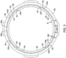
- Figures 2 and 3 depict plan views of the primary ring 28 showing the primary ring seal face 32 defined by a first edge 36 (e.g., a radially outer edge or periphery) and a second edge 38 (e.g., a radially inner edge or periphery) of the primary ring 28.
- first edge 36 e.g., a radially outer edge or periphery
- second edge 38 e.g., a radially inner edge or periphery
- the primary ring seal face 32 defines one or more channels that are configured to promote introducing process fluid between seal faces of a seal interface via a hydrostatic effect.
- the first edge 36 may be configured to be exposed to the process fluid and associated pressures.
- the seal face configurations discussed herein may be configured to be utilized in seal assemblies 10 that are used to maintain a fluid under pressure.
- the seal face configuration may be configured to facilitate lubrication within a seal interface when the fluid under pressure is held within a range from about 6.9 bar (100 pounds per square inch (psi)) or less to about 137.9 bar (2000 psi or more), or other suitable range.
- the seal face configuration may be configured to facilitate lubrication within a seal interface when the fluid under pressure is held within a range from about 41.4 bar (600 psi) to about 68.9 bar (1000 psi).
- the channels depicted in the primary ring seal face 32 of Figure 2 may include one or more circumferential channels 40 (e.g., when there are two or more circumferential channels 40, the circumferential channels 40 may be co-axial and/or take on one or more other suitable configurations) and a plurality of sub-channels 42 (e.g., radial channels or other channels radially extending from the circumferential channel 40).
- the plurality of sub-channels 42 may extend from the circumferential channel 40 such that the circumferential channel 40 and at least some of the plurality of sub-channels 42 may be fluidly connected and/or may form a continuous passageway.
- Such a configuration of channels may facilitate directing fluid into the seal interface of the seal assembly 10, distributing the fluid along the circumference of the seal interface, and increase a fluid opening force between the seal faces (e.g., the primary ring seal face 32 and the mating ring seal face 24) to reduce mechanical loads on the seal faces and improve seal performance.
- the channels are configured to take up a desired percentage of a surface area of the primary ring seal face 32 such that a leakage of process fluid may be mitigated.
- the channels are configured to take up less than ten (10) percent.
- the channels may be configured to take up less than about five (5) percent, and/or other suitable amount of a surface area of the primary ring seal face 32.
- the channels may be configured to take up about three (3) percent of a surface area of the primary ring seal face 32.
- the circumferential channel 40 may have an annular configuration (e.g., an annular channel having a single, continuous circumferential channel segment or portion forming a ring on or in the primary ring seal face, as depicted in Figure 2 ) or the circumferential channel 40 may be formed from a plurality of circumferential channel segments or portions spaced from one another (e.g., as depicted in Figure 3 ).
- the circumferential channel 40 may include two (2) circumferential channel segments (e.g., circumferential channel segments or portions 40a, 40b depicted in Figure 3 ), three (3) circumferential channel segments or portions, four (4) circumferential channel segments or portions, or other suitable number of circumferential channel segments or portions.
- each of the plurality of circumferential channel segments or portions may be located a same distance from a central axis of the primary ring 28.
- the circumferential channel 40 may take on a suitable configuration for distributing fluid along the primary ring seal face 32.
- Example configurations may include, but are not limited to a circular configuration, an oval configuration, a star configuration, and/or other suitable configurations, as desired.
- the circumferential channel 40 may be generally circular and may be co-axial with one or both of the first edge 36 and the second edge 38 of the primary ring 28.
- the circumferential channel 40 may be positioned at any location between the first edge 36 and the second edge 38 of the primary ring. In some cases, the circumferential channel 40 may be spaced from the first edge 36 and the second edge 38.
- the primary ring seal face 32 may have seal face width S between the first edge 36 and the second edge 38, and the circumferential channel 40 (e.g., a center of the circumferential channel 40) may be located within a range of one-fourth to one-half of a distance of the seal face width S, or other suitable range, from the first edge 36 or otherwise an edge configured to be adjacent process fluid.
- the circumferential channel 40 may be located at one-third of a distance of the seal face width S from the first edge 36, as depicted in Figures 2 and 3 .
- the plurality of sub-channels 42 may include a plurality of first sub-channels 42a and a plurality of second sub-channels 42b. Alternatively, the plurality of sub-channels 42 may consist solely of a plurality of first sub-channels 42a.
- the plurality of first sub-channels 42a may extend from the circumferential channel 40 to the first edge 36 defining the primary ring seal face 32. Such a configuration may facilitate promoting process fluid into the seal interface 35 as the plurality of first sub-channels in communication with the circumferential channel provide an avenue for pressurized process fluid to enter seal interface 35, circulate around the seal interface 35 via the circumferential channel 40 and hydrostatic effect, and cause hydrostatic lift between the primary ring seal face 32 and the mating ring seal face 24 when in use in a manner similar to the configuration depicted in Figure 1 .
- Such a configuration may form a hydrostatic seal between the primary ring seal face 32 and the mating ring seal face 24 at hydrostatic conditions, where a hydrostatic seal is known as a non-contacting mechanical seal that separates two different pressure zones used to establish a balanced pressure zone between two adjacent seal faces.
- the plurality of second sub-channels 42b may extend from the circumferential channel 40 toward the second edge 38 defining the primary ring seal face 32. Such a configuration may facilitate process fluid promoting hydrostatic lift between the primary ring seal face 32 and the mating ring seal face 24 by providing an avenue for the process fluid to penetrate deeper into the seal interface 35 than a location of the circumferential channel 40. In some cases, one or more of the plurality of second sub-channels 42b may have a terminal end 44 prior to reaching the second edge 38 such that process fluid may be used to lubricate the seal interface 35 while mitigating leakage of process fluid through the seal interface 35.
- the plurality of second sub-channels 42b may extend a distance from the circumferential channel 40 toward the second edge 38.
- the distance each of the second sub-channels 42b extend may be similar or the same for all of the second sub-channels 42b or one or more of the second sub-channels 42b may extend a distance from the circumferential channel 40 toward the second edge 38 that is different than a distance at least one other of the second sub-channels 42b may extend.
- the second sub-channels 42b may extend a distance within a range of one-fourth to one-half of a distance of the seal face width S or other suitable range.
- one or more of the plurality of second sub-channels 42b may extend a distance of one-third of a distance of the seal face width S, as depicted in Figures 2 and 3 .
- the plurality of first sub-channels 42a and the plurality of second sub-channels 42b may be configured in a suitable manner with respect to one another.
- the first sub-channels 42a of the plurality of the first sub-channels 42a may extend from the circumferential channel 40 at a same location as one of the plurality of second sub-channels 42b
- the first sub-channels 42a of the plurality of the first sub-channels 42 and the second sub-channels 42b may extend from the circumferential channel 40 in an alternating or staggered order along a length of the circumferential channel 40 (e.g., as depicted in Figures 2 and 3 )
- the plurality of first sub-channels 42a may be configured on the primary ring seal face 32 in one or more other suitable manners with respect to how the plurality of second sub-channels 42b are configured on the primary ring seal face 32.
- the sub-channels 42 may be spaced a suitable distance from each other along the circumferential channel 40. In some cases, the sub-channels 42 may be spaced a consistent distance from one another along the length of the circumferential channel, but this is not required. In one example, an angular separation between a same type of sub-channels 42 (e.g., between two first sub-channels 42a or between two second sub-channels 42b) may be within a range from about ten (10) degrees to about thirty (30) degrees or other suitable range.
- a distance between sub-channels 42 may be based on a ratio of a circumferential distance CD between the same type of sub-channels 42 to a radial span RS of a sub-channel 42 (e.g., a distance from a center of the circumferential channel 40 to a terminal end of the first sub-channel 42a or the second sub-channel 42b).
- the ratio of a circumferential distance CD between the same type of sub-channels 42 to a radial span RS of a sub-channel 42 may be within a range from about four (4) to about twenty (20) or other suitable range.
- the sub-channels 42 of a same type of sub-channel may be spaced along a length of the circumferential channel 40 such that the ratio of circumferential distance CD between the same type of sub-channels 42 to a radial span RS of the same type of sub-channel 42 may be about or may be eight (8) or less to facilitate promoting hydrostatic lift at the seal interface 35 while mitigating leakage of process fluid through the seal interface 35.
- a ratio of the circumferential distance between any two adjacent sub-channels 42 to a radial span of a sub-channel may be or may be about four (4) to facilitate promoting hydrostatic lift at the seal interface 35 while mitigating leakage of process fluid through the seal interface 35.
- Other ratio values may be utilized, as desired, to determine a number of sub-channels to utilize and/or a spacing between adjacent sub-channels 42.
- Figure 4 is a magnification of a portion of the illustrative primary ring 28 in Figure 2 that is within circle-4.
- the first sub-channels 42a have a width W 1
- the second sub-channels 42b have a width W 2
- the circumferential channel 40 has a width W 3 .
- the widths W 1 , W 2 , W 3 may be the same, however, it is contemplated that one or more channels may have a width that may be different than a width of at least one other channel.
- the widths W 1 , W 2 , W 3 may be configured to facilitate a flow of process fluid through the channels.
- the widths W 1 , W 2 , W 3 may be within a suitable rage of widths, such as within a range extending from about 0.025 mm (0.001 inches) to about 0.152 mm (0.006 inches) or other suitable range. In one example, the widths W 1 , W 2 , W 3 may be about 0.127 mm (0.005 inches).
- Figures 5-7 depict cross-sections of the primary ring 28 taken along lines 5-5, 6-6, and 7-7, respectively, of Figure 4 .
- the circumferential channel 40 is depicted in the primary ring seal face 32 as having a depth D 3 .
- the first sub-channel 42a is depicted as extending from the circumferential channel 40 to the first edge 36 of the primary ring 28, where the first sub-channel 42a is depicted in the primary ring seal face 32 as having a depth D 1 .
- the second sub-channel 42b is depicted as extending from the circumferential channel 40 to its terminal end 44, where the second sub-channel 42b is depicted in the primary ring seal face 32 as having a depth D 2 .
- the depths D 1 , D 2 , D 3 of the channels may be equal to one another or, alternatively, one or more of the depths D 1 , D 2 , D 3 may be different from another one of the depths D 1 , D 2 , D 3 .
- the depths D 1 , D 2 , D 3 may be configured to facilitate hydrostatic lift at the seal interface 35 by promoting the introduction of process fluid into the channels (e.g., the circumferential channel 40 and/or the sub-channels 42).
- the depths may be within a range of 0.025 mm (0.001 inches) and 0.127 mm (0.005 inches) or other suitable range.
- the depths D 1 , D 2 , D 3 may be equal to about 0.051 mm (0.002 inches), which is an order of magnitude deeper than depths of about 0.051 mm (0.0002 inches) used for dimple surface texturing. Channels of such depth may facilitate serving as a reservoir for fluid (e.g., in the event of a loss of pressurized fluid) and/or for collecting wear debris from the seal faces (e.g., the primary ring seal face 32 and/or the mating ring seal face 24), if there is any, which may facilitate prolonging a life of the seal assembly 10.
- fluid e.g., in the event of a loss of pressurized fluid
- wear debris e.g., the primary ring seal face 32 and/or the mating ring seal face 24
- the above described channels of the primary ring 28 may be formed in the primary ring 28 (or the mating ring 18) in a suitable manner capable of forming channels in hard materials (e.g., silicon carbide, tungsten carbide, etc.).
- a laser e.g., via laser engraving or ablating and/or other laser engraving or ablating techniques
- suitable machining application may be utilized to form the circumferential channel 40 and/or the sub-channels 42 (e.g., the first sub-channels 42a and/or the second sub-channels 42b) in a surface of the primary ring seal face 32 of the primary ring 28 and/or a surface of the seal face 24 of the mating ring 18, such that the formed circumferential channel 40 and the formed sub-channels 42 are fluidly connected (e.g., in some cases, the fluidly connected formed circumferential channel 40 and formed sub-channels 42 may form a continuous passageway to facilitate pressurized process fluid traveling around the seal interface 35).
- a four (4) inch outer diameter seal assembly with a seventy (70) percent balance ratio and utilizing SiC as the material for the primary ring seal face and the mating ring seal face may include a circumferential channel and a plurality of sub-channels on the primary ring seal face.
- the circumferential channel and the sub-channels had a depth of about 0.051 mm (0.002 inches) and a width of about 0.127 mm (0.005 inches).
- the circumferential channel may be annular and located about one-third a width of the primary ring seal face from an outer diameter of the primary ring seal face, first sub-channels of the plurality of sub-channels may extend from the circumferential channel to the outer diameter circumference of the seal face, and second sub-channels of the plurality of sub-channels may extend from the circumferential channel toward an inner diameter circumference of the seal face about one-third the width of the primary ring seal face.
- the first sub-channels and the second sub-channels may be staggered equal distances away from one another.
- the sub-channels of a same type of sub-channel may be spaced along a length of the circumferential channel such that the ratio of circumferential distance between the same type of sub-channels to a radial span of the same type of sub-channel is about eight (8).
- Such a configured seal face assembly was tested for 100 hours in a pump holding water at 27 °C (80 degrees Fahrenheit), the water having a maximum fluid pressure of 68.9 bar (1000 psi), and the pump having a shaft rotation of 3600 rotations per minute. Post-test examination of the seal assembly revealed little wear, while leakage remained low (i.e., a leakage rate of 0-6 grams/hour) and/or within tolerances.
Landscapes
- Engineering & Computer Science (AREA)
- General Engineering & Computer Science (AREA)
- Mechanical Engineering (AREA)
- Physics & Mathematics (AREA)
- Optics & Photonics (AREA)
- Plasma & Fusion (AREA)
- Mechanical Sealing (AREA)
- Sealing Devices (AREA)
Claims (15)
- Ensemble de joint hydrostatique (10) pour assurer l'étanchéité d'un liquide comprenant :une première bague (28) ayant un premier côté (32) limité par un premier bord (36) et un deuxième bord (38) ; etune deuxième bague (18) ayant un deuxième côté (24) faisant face au premier côté ;dans lequel un canal circonférentiel (40) s'étend le long du premier côté (32) entre, et espacé du premier bord (36) et du deuxième bord (38) ;dans lequel une pluralité de sous-canaux (42) s'étendent à partir du canal circonférentiel (40) le long du premier côté (32) de la première bague (28) ;dans lequel la première bague (28) et la deuxième bague (18) forment un joint hydrostatique entre le premier côté (32) et le deuxième côté (24),caractérisé en ce que le canal circonférentiel (40) et la pluralité de sous-canaux (42) sont configurés pour occuper moins de dix pour cent d'une superficie du premier côté (32).
- Ensemble joint (10) de la revendication 1, dans lequel la pluralité de sous-canaux (42) incluent une pluralité de premiers sous-canaux (42a) s'étendant à partir du canal circonférentiel (40) jusqu'au premier bord (36) le long du premier côté (32) de la première bague (28), et
dans lequel le canal circonférentiel (40) et la pluralité de premiers sous-canaux (42a) favorisent l'introduction de fluide entre le premier côté (32) de la première bague (28) et le deuxième côté (24) de la deuxième bague (18) provoquant ainsi un levage hydrostatique entre le premier côté (32) de la première bague (28) et le deuxième côté (24) de la deuxième bague (18). - Ensemble joint (10) de la revendication 2, dans lequel la pluralité de sous-canaux (42) incluent une pluralité de deuxièmes sous-canaux (42b) s'étendant le long du premier côté (32) à partir du canal circonférentiel (40) vers le deuxième bord (38), et
dans lequel la pluralité de sous-canaux (42) s'étendant à partir du canal circonférentiel (40) sont localisés sur le premier côté (32) de la première bague (28) de telle sorte que des premiers sous-canaux de la pluralité de premiers sous-canaux (42a) et des deuxièmes sous-canaux de la pluralité de deuxièmes sous-canaux (42b) s'étendent à partir du canal circonférentiel (40) suivant un ordre alternant le long d'une longueur du canal circonférentiel. - Ensemble joint (10) de la revendication 2, dans lequel un deuxième sous-canal de la pluralité de deuxièmes sous-canaux (42b) s'étend à partir du canal circonférentiel (40) jusqu'à une extrémité terminale (44) laquelle est espacée du deuxième bord (38).
- Ensemble joint (10) de la revendication 2, dans lequel un rapport d'une distance circonférentielle entre chaque premier sous-canal de la pluralité de premiers sous-canaux (42a) à une portée radiale de chaque premier sous-canal est d'environ 8 et, facultativement, est d'environ 4.
- Ensemble joint (10) de la revendication 2, dans lequel le premier bord (36) de la première bague (28) est configuré pour se trouver sur un côté pressurisé du joint et le joint est configuré pour offrir une étanchéité contre des pressions sur le côté pressurisé du joint au sein d'une plage d'environ 41,4 bar (600 psi) à environ 68,9 bar (1000 psi).
- Ensemble joint (10) de la revendication 1, dans lequel le canal circonférentiel (40) est coaxial avec un bord, ou les deux, parmi le premier bord (36) et le deuxième bord (38) et inclut une première portion de canal circonférentiel (40a) et une deuxième portion de canal circonférentiel (40b) séparée fluidiquement de la première portion de canal circonférentiel.
- Ensemble joint (10) de la revendication 1, dans lequel le premier côté (32) de la première bague (28) a une largeur s'étendant à partir du premier bord (36) jusqu'au deuxième bord (38) et le canal circonférentiel (40) est espacé du premier bord (36) d'une distance d'un tiers de la largeur du premier côté (32) de la première bague (28).
- Ensemble joint (10) de la revendication 1, dans lequel le canal circonférentiel (40) a une profondeur d'environ 0,051 mm (0,002 pouce).
- Ensemble joint (10) de la revendication 1, dans lequel le canal circonférentiel (40) a une largeur entre environ 0,025 mm (0,001 pouce) et 0,152 mm (0,006 pouce).
- Ensemble joint (10) de la revendication 1, dans lequel un côté, ou les deux, parmi le premier côté (32) de la première bague (28) et le deuxième côté (24) de la deuxième bague (18) sont formés à partir d'un ou de plusieurs matériaux sélectionnés à partir d'un groupe consistant en carbone, carbure de silicium, et carbure de tungstène.
- Procédé de formation d'une bague annulaire pour un ensemble de joint hydrostatique (10), le procédé comprenant :le fait de former un canal circonférentiel (40) dans une surface d'une bague annulaire (28) ; etle fait de former une pluralité de premiers canaux radiaux (42a) dans la surface de la bague annulaire (28), la pluralité de premiers canaux radiaux (42a) s'étendant à partir du canal circonférentiel (40) jusqu'à un premier bord de la surface ;dans lequel le canal circonférentiel (40) raccorde fluidiquement la pluralité de premiers canaux radiaux (42a) dans la surface de la bague annulaire (28) ; etdans lequel le canal circonférentiel (40) et la pluralité de premiers canaux radiaux (42a) sont configurés pour occuper moins de dix pour cent d'une superficie de la surface de la bague annulaire (28).
- Procédé de la revendication 12, comprenant en outre :le fait de former une pluralité de deuxièmes canaux radiaux (42b) dans la surface de la bague annulaire, la pluralité de deuxièmes canaux radiaux (42b) s'étendant à partir du canal circonférentiel vers un deuxième bord (38) de la surface ;dans lequel le canal circonférentiel (40) raccorde fluidiquement la pluralité de premiers canaux radiaux (42a) dans la surface de la bague annulaire et la pluralité de deuxièmes canaux radiaux (42b) dans la surface de la bague annulaire (28).
- Procédé de la revendication 12, dans lequel le canal circonférentiel formé (40), la pluralité de premiers canaux radiaux (42a), et la pluralité de deuxièmes canaux radiaux (42b) occupent moins de cinq pour cent d'une superficie de la surface de la bague annulaire (28).
- Procédé de la revendication 12, dans lequel le canal circonférentiel formé (40), la pluralité de premiers canaux radiaux (42a), et la pluralité de deuxièmes canaux radiaux (42b) sont formés par l'intermédiaire d'une gravure laser.
Applications Claiming Priority (2)
| Application Number | Priority Date | Filing Date | Title |
|---|---|---|---|
| US201862682496P | 2018-06-08 | 2018-06-08 | |
| PCT/US2019/035305 WO2019236524A1 (fr) | 2018-06-08 | 2019-06-04 | Joint mécanique avec une face d'étanchéité dotée de canaux |
Publications (3)
| Publication Number | Publication Date |
|---|---|
| EP3803165A1 EP3803165A1 (fr) | 2021-04-14 |
| EP3803165A4 EP3803165A4 (fr) | 2022-03-09 |
| EP3803165B1 true EP3803165B1 (fr) | 2025-01-29 |
Family
ID=68770594
Family Applications (1)
| Application Number | Title | Priority Date | Filing Date |
|---|---|---|---|
| EP19815144.1A Active EP3803165B1 (fr) | 2018-06-08 | 2019-06-04 | Joint mécanique avec une face d'étanchéité dotée de canaux |
Country Status (4)
| Country | Link |
|---|---|
| US (2) | US20210254721A1 (fr) |
| EP (1) | EP3803165B1 (fr) |
| CN (1) | CN112703341B (fr) |
| WO (1) | WO2019236524A1 (fr) |
Families Citing this family (1)
| Publication number | Priority date | Publication date | Assignee | Title |
|---|---|---|---|---|
| US11434828B2 (en) | 2020-11-25 | 2022-09-06 | Raytheon Technologies Corporation | Face seal arrangement for reduced force and pressure |
Family Cites Families (30)
| Publication number | Priority date | Publication date | Assignee | Title |
|---|---|---|---|---|
| US1876520A (en) * | 1931-04-22 | 1932-09-06 | Shaft packing | |
| US2536292A (en) * | 1948-06-03 | 1951-01-02 | Kollsman Paul | Rotary fluid pressure seal |
| US3804424A (en) * | 1972-04-24 | 1974-04-16 | Crane Packing Co | Gap seal with thermal and pressure distortion compensation |
| US4407512A (en) | 1976-01-02 | 1983-10-04 | John Crane-Houdaille, Inc. | High pressure rotary mechanical seal |
| JPS60190035A (ja) | 1984-03-09 | 1985-09-27 | Nec Corp | 衛星通信送信電力制御方式 |
| DE3447102A1 (de) * | 1984-12-22 | 1986-07-10 | MAN Gutehoffnungshütte GmbH, 4200 Oberhausen | Hydrostatische wellendichtung bzw. hydrodynamische wellendichtung |
| US4887395A (en) * | 1987-02-17 | 1989-12-19 | University Of New Mexico | Wavy-tilt-dam seal ring and apparatus for shaping seal rings |
| US5174584A (en) * | 1991-07-15 | 1992-12-29 | General Electric Company | Fluid bearing face seal for gas turbine engines |
| US5722665A (en) * | 1992-02-26 | 1998-03-03 | Durametallic Corporation | Spiral groove face seal |
| US5201531A (en) * | 1992-04-02 | 1993-04-13 | John Crane Inc. | Face seal with double spiral grooves |
| CA2170746C (fr) * | 1993-09-01 | 2005-01-25 | Josef Sedy | Joint a portee plane, avec rainures a angle et annulaires |
| US5498007A (en) * | 1994-02-01 | 1996-03-12 | Durametallic Corporation | Double gas barrier seal |
| US5941532A (en) * | 1996-06-20 | 1999-08-24 | Rexnord Corporation | Aerospace housing and shaft assembly with noncontacting seal |
| US6152452A (en) * | 1997-10-17 | 2000-11-28 | Wang; Yuming | Face seal with spiral grooves |
| US6142478A (en) * | 1998-02-06 | 2000-11-07 | John Crane Inc. | Gas lubricated slow speed seal |
| US6132094A (en) * | 1998-12-21 | 2000-10-17 | Fmc Corporation | Multiple groove thrust bearing |
| US6341782B1 (en) * | 2000-03-03 | 2002-01-29 | Surface Technologies Ltd | Lubricated seals having micropores |
| US7044470B2 (en) * | 2000-07-12 | 2006-05-16 | Perkinelmer, Inc. | Rotary face seal assembly |
| WO2004092621A1 (fr) | 2003-04-09 | 2004-10-28 | Dimitrios Dardalis | Appareil et procede pour faire tourner un joint mecanique hydrodynamique d'un moteur chemise |
| JP4719414B2 (ja) * | 2003-12-22 | 2011-07-06 | イーグル工業株式会社 | 摺動部品 |
| US7494130B2 (en) * | 2006-02-13 | 2009-02-24 | Freudenberg-Nok General Partnership | Bi-directional pattern for dynamic seals |
| CN103635728B (zh) * | 2011-07-01 | 2017-07-07 | 伊顿公司 | 勺形流体动力密封装置 |
| CN104334939B (zh) * | 2012-08-04 | 2017-05-31 | 伊格尔工业股份有限公司 | 滑动部件 |
| US9587745B2 (en) * | 2013-04-24 | 2017-03-07 | Eagle Industry Co., Ltd. | Sliding component |
| US9695940B2 (en) * | 2013-12-18 | 2017-07-04 | Kaydon Ring & Seal, Inc. | Bidirectional lift-off circumferential shaft seal segment and a shaft seal including a plurality of the segments |
| US9695944B2 (en) * | 2013-12-23 | 2017-07-04 | Flowserve Management Company | Electrical corrosion resistant mechanical seal |
| EP3112078B1 (fr) * | 2014-02-24 | 2020-04-15 | Eagle Industry Co., Ltd. | Élément glissant et procédé de traitement d'élément glissant |
| EP3204666B1 (fr) | 2014-10-06 | 2019-04-10 | John Crane Inc. | Garniture mécanique d'étanchéité à profilé de surface en forme de tampon hydraulique |
| CN107208804A (zh) * | 2015-01-31 | 2017-09-26 | 伊格尔工业股份有限公司 | 滑动部件 |
| CN109923340B (zh) * | 2016-11-16 | 2020-09-11 | 伊格尔工业股份有限公司 | 滑动组件 |
-
2019
- 2019-06-04 EP EP19815144.1A patent/EP3803165B1/fr active Active
- 2019-06-04 CN CN201980053630.6A patent/CN112703341B/zh active Active
- 2019-06-04 WO PCT/US2019/035305 patent/WO2019236524A1/fr not_active Ceased
- 2019-06-04 US US16/972,692 patent/US20210254721A1/en not_active Abandoned
-
2023
- 2023-11-29 US US18/523,413 patent/US20240093784A1/en active Pending
Also Published As
| Publication number | Publication date |
|---|---|
| WO2019236524A1 (fr) | 2019-12-12 |
| CN112703341B (zh) | 2024-01-23 |
| CN112703341A (zh) | 2021-04-23 |
| US20210254721A1 (en) | 2021-08-19 |
| US20240093784A1 (en) | 2024-03-21 |
| EP3803165A1 (fr) | 2021-04-14 |
| EP3803165A4 (fr) | 2022-03-09 |
Similar Documents
| Publication | Publication Date | Title |
|---|---|---|
| EP1600673B1 (fr) | Garniture mécanique d'étanchéité pourvue d'un dispositif de pompage hydrodynamique | |
| EP2853787B1 (fr) | Composant coulissant | |
| EP3258145B1 (fr) | Élément de glissement | |
| US9574666B2 (en) | Mechanical face seal with a reverse trapezoidal face pattern | |
| US5509664A (en) | Segmented hydrodynamic seals for sealing a rotatable shaft | |
| EP2616698B1 (fr) | Système d'étanchéité intercalaire servant à réduire au minimum la torsion induite par pression | |
| EP2350503B1 (fr) | Système de joint circonférentiel hydrodynamique pour grandes translations | |
| US5174584A (en) | Fluid bearing face seal for gas turbine engines | |
| AU685502B2 (en) | Face seal with angled and annular grooves | |
| EP2940353B1 (fr) | Élément coulissant | |
| EP3627011B1 (fr) | Composant coulissant | |
| EP3653914B1 (fr) | Pièces coulissantes | |
| US20020093141A1 (en) | Bi-direction rotatable face seal with spiral grooves | |
| EP3508763A1 (fr) | Élément coulissant | |
| EP2681471B1 (fr) | Joint segmenté à élément de régulation de charge axiale | |
| US20080157479A1 (en) | Low and reverse pressure application hydrodynamic pressurizing seals | |
| WO2005106295A1 (fr) | Ensemble joint etanche aux gaz | |
| EP2948682B1 (fr) | Joint de sortie de boîte de vitesses | |
| US20240093784A1 (en) | Mechanical seal with a seal face having channels | |
| CA2147739A1 (fr) | Joint mecanique a double rangee de rainures |
Legal Events
| Date | Code | Title | Description |
|---|---|---|---|
| STAA | Information on the status of an ep patent application or granted ep patent |
Free format text: STATUS: THE INTERNATIONAL PUBLICATION HAS BEEN MADE |
|
| PUAI | Public reference made under article 153(3) epc to a published international application that has entered the european phase |
Free format text: ORIGINAL CODE: 0009012 |
|
| STAA | Information on the status of an ep patent application or granted ep patent |
Free format text: STATUS: REQUEST FOR EXAMINATION WAS MADE |
|
| 17P | Request for examination filed |
Effective date: 20210108 |
|
| AK | Designated contracting states |
Kind code of ref document: A1 Designated state(s): AL AT BE BG CH CY CZ DE DK EE ES FI FR GB GR HR HU IE IS IT LI LT LU LV MC MK MT NL NO PL PT RO RS SE SI SK SM TR |
|
| AX | Request for extension of the european patent |
Extension state: BA ME |
|
| DAV | Request for validation of the european patent (deleted) | ||
| DAX | Request for extension of the european patent (deleted) | ||
| A4 | Supplementary search report drawn up and despatched |
Effective date: 20220209 |
|
| RIC1 | Information provided on ipc code assigned before grant |
Ipc: F16J 15/54 20060101ALI20220203BHEP Ipc: F16J 15/40 20060101ALI20220203BHEP Ipc: F16J 15/16 20060101ALI20220203BHEP Ipc: F16C 33/74 20060101ALI20220203BHEP Ipc: B23K 26/364 20140101ALI20220203BHEP Ipc: F16J 15/34 20060101AFI20220203BHEP |
|
| STAA | Information on the status of an ep patent application or granted ep patent |
Free format text: STATUS: EXAMINATION IS IN PROGRESS |
|
| 17Q | First examination report despatched |
Effective date: 20221117 |
|
| P01 | Opt-out of the competence of the unified patent court (upc) registered |
Effective date: 20230522 |
|
| TPAC | Observations filed by third parties |
Free format text: ORIGINAL CODE: EPIDOSNTIPA |
|
| GRAP | Despatch of communication of intention to grant a patent |
Free format text: ORIGINAL CODE: EPIDOSNIGR1 |
|
| STAA | Information on the status of an ep patent application or granted ep patent |
Free format text: STATUS: GRANT OF PATENT IS INTENDED |
|
| INTG | Intention to grant announced |
Effective date: 20241002 |
|
| GRAS | Grant fee paid |
Free format text: ORIGINAL CODE: EPIDOSNIGR3 |
|
| GRAA | (expected) grant |
Free format text: ORIGINAL CODE: 0009210 |
|
| STAA | Information on the status of an ep patent application or granted ep patent |
Free format text: STATUS: THE PATENT HAS BEEN GRANTED |
|
| AK | Designated contracting states |
Kind code of ref document: B1 Designated state(s): AL AT BE BG CH CY CZ DE DK EE ES FI FR GB GR HR HU IE IS IT LI LT LU LV MC MK MT NL NO PL PT RO RS SE SI SK SM TR |
|
| REG | Reference to a national code |
Ref country code: GB Ref legal event code: FG4D |
|
| REG | Reference to a national code |
Ref country code: CH Ref legal event code: EP |
|
| REG | Reference to a national code |
Ref country code: DE Ref legal event code: R096 Ref document number: 602019065445 Country of ref document: DE |
|
| REG | Reference to a national code |
Ref country code: IE Ref legal event code: FG4D |
|
| REG | Reference to a national code |
Ref country code: NL Ref legal event code: MP Effective date: 20250129 |
|
| PG25 | Lapsed in a contracting state [announced via postgrant information from national office to epo] |
Ref country code: NL Free format text: LAPSE BECAUSE OF FAILURE TO SUBMIT A TRANSLATION OF THE DESCRIPTION OR TO PAY THE FEE WITHIN THE PRESCRIBED TIME-LIMIT Effective date: 20250129 |
|
| PG25 | Lapsed in a contracting state [announced via postgrant information from national office to epo] |
Ref country code: RS Free format text: LAPSE BECAUSE OF FAILURE TO SUBMIT A TRANSLATION OF THE DESCRIPTION OR TO PAY THE FEE WITHIN THE PRESCRIBED TIME-LIMIT Effective date: 20250429 |
|
| PG25 | Lapsed in a contracting state [announced via postgrant information from national office to epo] |
Ref country code: FI Free format text: LAPSE BECAUSE OF FAILURE TO SUBMIT A TRANSLATION OF THE DESCRIPTION OR TO PAY THE FEE WITHIN THE PRESCRIBED TIME-LIMIT Effective date: 20250129 |
|
| PG25 | Lapsed in a contracting state [announced via postgrant information from national office to epo] |
Ref country code: PL Free format text: LAPSE BECAUSE OF FAILURE TO SUBMIT A TRANSLATION OF THE DESCRIPTION OR TO PAY THE FEE WITHIN THE PRESCRIBED TIME-LIMIT Effective date: 20250129 |
|
| PGFP | Annual fee paid to national office [announced via postgrant information from national office to epo] |
Ref country code: DE Payment date: 20250507 Year of fee payment: 7 |
|
| PG25 | Lapsed in a contracting state [announced via postgrant information from national office to epo] |
Ref country code: ES Free format text: LAPSE BECAUSE OF FAILURE TO SUBMIT A TRANSLATION OF THE DESCRIPTION OR TO PAY THE FEE WITHIN THE PRESCRIBED TIME-LIMIT Effective date: 20250129 |
|
| PGFP | Annual fee paid to national office [announced via postgrant information from national office to epo] |
Ref country code: GB Payment date: 20250508 Year of fee payment: 7 |
|
| REG | Reference to a national code |
Ref country code: LT Ref legal event code: MG9D |
|
| PG25 | Lapsed in a contracting state [announced via postgrant information from national office to epo] |
Ref country code: IS Free format text: LAPSE BECAUSE OF FAILURE TO SUBMIT A TRANSLATION OF THE DESCRIPTION OR TO PAY THE FEE WITHIN THE PRESCRIBED TIME-LIMIT Effective date: 20250529 Ref country code: NO Free format text: LAPSE BECAUSE OF FAILURE TO SUBMIT A TRANSLATION OF THE DESCRIPTION OR TO PAY THE FEE WITHIN THE PRESCRIBED TIME-LIMIT Effective date: 20250429 |
|
| PGFP | Annual fee paid to national office [announced via postgrant information from national office to epo] |
Ref country code: IT Payment date: 20250522 Year of fee payment: 7 |
|
| REG | Reference to a national code |
Ref country code: AT Ref legal event code: MK05 Ref document number: 1763726 Country of ref document: AT Kind code of ref document: T Effective date: 20250129 |
|
| PG25 | Lapsed in a contracting state [announced via postgrant information from national office to epo] |
Ref country code: HR Free format text: LAPSE BECAUSE OF FAILURE TO SUBMIT A TRANSLATION OF THE DESCRIPTION OR TO PAY THE FEE WITHIN THE PRESCRIBED TIME-LIMIT Effective date: 20250129 |
|
| PG25 | Lapsed in a contracting state [announced via postgrant information from national office to epo] |
Ref country code: LV Free format text: LAPSE BECAUSE OF FAILURE TO SUBMIT A TRANSLATION OF THE DESCRIPTION OR TO PAY THE FEE WITHIN THE PRESCRIBED TIME-LIMIT Effective date: 20250129 Ref country code: PT Free format text: LAPSE BECAUSE OF FAILURE TO SUBMIT A TRANSLATION OF THE DESCRIPTION OR TO PAY THE FEE WITHIN THE PRESCRIBED TIME-LIMIT Effective date: 20250529 |
|
| PGFP | Annual fee paid to national office [announced via postgrant information from national office to epo] |
Ref country code: FR Payment date: 20250508 Year of fee payment: 7 |
|
| PG25 | Lapsed in a contracting state [announced via postgrant information from national office to epo] |
Ref country code: GR Free format text: LAPSE BECAUSE OF FAILURE TO SUBMIT A TRANSLATION OF THE DESCRIPTION OR TO PAY THE FEE WITHIN THE PRESCRIBED TIME-LIMIT Effective date: 20250430 Ref country code: BG Free format text: LAPSE BECAUSE OF FAILURE TO SUBMIT A TRANSLATION OF THE DESCRIPTION OR TO PAY THE FEE WITHIN THE PRESCRIBED TIME-LIMIT Effective date: 20250129 |
|
| PG25 | Lapsed in a contracting state [announced via postgrant information from national office to epo] |
Ref country code: AT Free format text: LAPSE BECAUSE OF FAILURE TO SUBMIT A TRANSLATION OF THE DESCRIPTION OR TO PAY THE FEE WITHIN THE PRESCRIBED TIME-LIMIT Effective date: 20250129 |
|
| PG25 | Lapsed in a contracting state [announced via postgrant information from national office to epo] |
Ref country code: SE Free format text: LAPSE BECAUSE OF FAILURE TO SUBMIT A TRANSLATION OF THE DESCRIPTION OR TO PAY THE FEE WITHIN THE PRESCRIBED TIME-LIMIT Effective date: 20250129 |
|
| PG25 | Lapsed in a contracting state [announced via postgrant information from national office to epo] |
Ref country code: SM Free format text: LAPSE BECAUSE OF FAILURE TO SUBMIT A TRANSLATION OF THE DESCRIPTION OR TO PAY THE FEE WITHIN THE PRESCRIBED TIME-LIMIT Effective date: 20250129 |
|
| PG25 | Lapsed in a contracting state [announced via postgrant information from national office to epo] |
Ref country code: DK Free format text: LAPSE BECAUSE OF FAILURE TO SUBMIT A TRANSLATION OF THE DESCRIPTION OR TO PAY THE FEE WITHIN THE PRESCRIBED TIME-LIMIT Effective date: 20250129 |
|
| PG25 | Lapsed in a contracting state [announced via postgrant information from national office to epo] |
Ref country code: CZ Free format text: LAPSE BECAUSE OF FAILURE TO SUBMIT A TRANSLATION OF THE DESCRIPTION OR TO PAY THE FEE WITHIN THE PRESCRIBED TIME-LIMIT Effective date: 20250129 Ref country code: EE Free format text: LAPSE BECAUSE OF FAILURE TO SUBMIT A TRANSLATION OF THE DESCRIPTION OR TO PAY THE FEE WITHIN THE PRESCRIBED TIME-LIMIT Effective date: 20250129 |
|
| PG25 | Lapsed in a contracting state [announced via postgrant information from national office to epo] |
Ref country code: RO Free format text: LAPSE BECAUSE OF FAILURE TO SUBMIT A TRANSLATION OF THE DESCRIPTION OR TO PAY THE FEE WITHIN THE PRESCRIBED TIME-LIMIT Effective date: 20250129 |
|
| PG25 | Lapsed in a contracting state [announced via postgrant information from national office to epo] |
Ref country code: SK Free format text: LAPSE BECAUSE OF FAILURE TO SUBMIT A TRANSLATION OF THE DESCRIPTION OR TO PAY THE FEE WITHIN THE PRESCRIBED TIME-LIMIT Effective date: 20250129 |
|
| REG | Reference to a national code |
Ref country code: DE Ref legal event code: R097 Ref document number: 602019065445 Country of ref document: DE |
|
| PLBE | No opposition filed within time limit |
Free format text: ORIGINAL CODE: 0009261 |
|
| STAA | Information on the status of an ep patent application or granted ep patent |
Free format text: STATUS: NO OPPOSITION FILED WITHIN TIME LIMIT |
|
| REG | Reference to a national code |
Ref country code: CH Ref legal event code: L10 Free format text: ST27 STATUS EVENT CODE: U-0-0-L10-L00 (AS PROVIDED BY THE NATIONAL OFFICE) Effective date: 20251210 |
|
| 26N | No opposition filed |
Effective date: 20251030 |
|
| REG | Reference to a national code |
Ref country code: CH Ref legal event code: H13 Free format text: ST27 STATUS EVENT CODE: U-0-0-H10-H13 (AS PROVIDED BY THE NATIONAL OFFICE) Effective date: 20260127 |
|
| PG25 | Lapsed in a contracting state [announced via postgrant information from national office to epo] |
Ref country code: MC Free format text: LAPSE BECAUSE OF FAILURE TO SUBMIT A TRANSLATION OF THE DESCRIPTION OR TO PAY THE FEE WITHIN THE PRESCRIBED TIME-LIMIT Effective date: 20250129 |
|
| PG25 | Lapsed in a contracting state [announced via postgrant information from national office to epo] |
Ref country code: LU Free format text: LAPSE BECAUSE OF NON-PAYMENT OF DUE FEES Effective date: 20250604 |
|
| REG | Reference to a national code |
Ref country code: BE Ref legal event code: MM Effective date: 20250630 |
|
| PG25 | Lapsed in a contracting state [announced via postgrant information from national office to epo] |
Ref country code: IE Free format text: LAPSE BECAUSE OF NON-PAYMENT OF DUE FEES Effective date: 20250604 |
|
| PG25 | Lapsed in a contracting state [announced via postgrant information from national office to epo] |
Ref country code: BE Free format text: LAPSE BECAUSE OF NON-PAYMENT OF DUE FEES Effective date: 20250630 |
|
| PG25 | Lapsed in a contracting state [announced via postgrant information from national office to epo] |
Ref country code: CH Free format text: LAPSE BECAUSE OF NON-PAYMENT OF DUE FEES Effective date: 20250630 |