EP3803175B1 - Composant tubulaire d'un matériau métallique - Google Patents
Composant tubulaire d'un matériau métallique Download PDFInfo
- Publication number
- EP3803175B1 EP3803175B1 EP19725359.4A EP19725359A EP3803175B1 EP 3803175 B1 EP3803175 B1 EP 3803175B1 EP 19725359 A EP19725359 A EP 19725359A EP 3803175 B1 EP3803175 B1 EP 3803175B1
- Authority
- EP
- European Patent Office
- Prior art keywords
- pipe
- annular space
- jacket
- pipe component
- connecting element
- Prior art date
- Legal status (The legal status is an assumption and is not a legal conclusion. Google has not performed a legal analysis and makes no representation as to the accuracy of the status listed.)
- Active
Links
Images

Classifications
-
- F—MECHANICAL ENGINEERING; LIGHTING; HEATING; WEAPONS; BLASTING
- F16—ENGINEERING ELEMENTS AND UNITS; GENERAL MEASURES FOR PRODUCING AND MAINTAINING EFFECTIVE FUNCTIONING OF MACHINES OR INSTALLATIONS; THERMAL INSULATION IN GENERAL
- F16L—PIPES; JOINTS OR FITTINGS FOR PIPES; SUPPORTS FOR PIPES, CABLES OR PROTECTIVE TUBING; MEANS FOR THERMAL INSULATION IN GENERAL
- F16L53/00—Heating of pipes or pipe systems; Cooling of pipes or pipe systems
- F16L53/70—Cooling of pipes or pipe systems
-
- B—PERFORMING OPERATIONS; TRANSPORTING
- B33—ADDITIVE MANUFACTURING TECHNOLOGY
- B33Y—ADDITIVE MANUFACTURING, i.e. MANUFACTURING OF THREE-DIMENSIONAL [3D] OBJECTS BY ADDITIVE DEPOSITION, ADDITIVE AGGLOMERATION OR ADDITIVE LAYERING, e.g. BY 3D PRINTING, STEREOLITHOGRAPHY OR SELECTIVE LASER SINTERING
- B33Y80/00—Products made by additive manufacturing
-
- F—MECHANICAL ENGINEERING; LIGHTING; HEATING; WEAPONS; BLASTING
- F16—ENGINEERING ELEMENTS AND UNITS; GENERAL MEASURES FOR PRODUCING AND MAINTAINING EFFECTIVE FUNCTIONING OF MACHINES OR INSTALLATIONS; THERMAL INSULATION IN GENERAL
- F16L—PIPES; JOINTS OR FITTINGS FOR PIPES; SUPPORTS FOR PIPES, CABLES OR PROTECTIVE TUBING; MEANS FOR THERMAL INSULATION IN GENERAL
- F16L53/00—Heating of pipes or pipe systems; Cooling of pipes or pipe systems
- F16L53/30—Heating of pipes or pipe systems
- F16L53/32—Heating of pipes or pipe systems using hot fluids
-
- F—MECHANICAL ENGINEERING; LIGHTING; HEATING; WEAPONS; BLASTING
- F16—ENGINEERING ELEMENTS AND UNITS; GENERAL MEASURES FOR PRODUCING AND MAINTAINING EFFECTIVE FUNCTIONING OF MACHINES OR INSTALLATIONS; THERMAL INSULATION IN GENERAL
- F16L—PIPES; JOINTS OR FITTINGS FOR PIPES; SUPPORTS FOR PIPES, CABLES OR PROTECTIVE TUBING; MEANS FOR THERMAL INSULATION IN GENERAL
- F16L9/00—Rigid pipes
- F16L9/18—Double-walled pipes; Multi-channel pipes or pipe assemblies
-
- F—MECHANICAL ENGINEERING; LIGHTING; HEATING; WEAPONS; BLASTING
- F28—HEAT EXCHANGE IN GENERAL
- F28D—HEAT-EXCHANGE APPARATUS, NOT PROVIDED FOR IN ANOTHER SUBCLASS, IN WHICH THE HEAT-EXCHANGE MEDIA DO NOT COME INTO DIRECT CONTACT
- F28D7/00—Heat-exchange apparatus having stationary tubular conduit assemblies for both heat-exchange media, the media being in contact with different sides of a conduit wall
- F28D7/10—Heat-exchange apparatus having stationary tubular conduit assemblies for both heat-exchange media, the media being in contact with different sides of a conduit wall the conduits being arranged one within the other, e.g. concentrically
- F28D7/106—Heat-exchange apparatus having stationary tubular conduit assemblies for both heat-exchange media, the media being in contact with different sides of a conduit wall the conduits being arranged one within the other, e.g. concentrically consisting of two coaxial conduits or modules of two coaxial conduits
-
- B—PERFORMING OPERATIONS; TRANSPORTING
- B01—PHYSICAL OR CHEMICAL PROCESSES OR APPARATUS IN GENERAL
- B01J—CHEMICAL OR PHYSICAL PROCESSES, e.g. CATALYSIS OR COLLOID CHEMISTRY; THEIR RELEVANT APPARATUS
- B01J2208/00—Processes carried out in the presence of solid particles; Reactors therefor
- B01J2208/00008—Controlling the process
- B01J2208/00017—Controlling the temperature
- B01J2208/00106—Controlling the temperature by indirect heat exchange
- B01J2208/00168—Controlling the temperature by indirect heat exchange with heat exchange elements outside the bed of solid particles
- B01J2208/00212—Plates; Jackets; Cylinders
-
- B—PERFORMING OPERATIONS; TRANSPORTING
- B01—PHYSICAL OR CHEMICAL PROCESSES OR APPARATUS IN GENERAL
- B01J—CHEMICAL OR PHYSICAL PROCESSES, e.g. CATALYSIS OR COLLOID CHEMISTRY; THEIR RELEVANT APPARATUS
- B01J2219/00—Chemical, physical or physico-chemical processes in general; Their relevant apparatus
- B01J2219/00049—Controlling or regulating processes
- B01J2219/00051—Controlling the temperature
- B01J2219/00074—Controlling the temperature by indirect heating or cooling employing heat exchange fluids
- B01J2219/00076—Controlling the temperature by indirect heating or cooling employing heat exchange fluids with heat exchange elements inside the reactor
- B01J2219/00085—Plates; Jackets; Cylinders
-
- B—PERFORMING OPERATIONS; TRANSPORTING
- B01—PHYSICAL OR CHEMICAL PROCESSES OR APPARATUS IN GENERAL
- B01J—CHEMICAL OR PHYSICAL PROCESSES, e.g. CATALYSIS OR COLLOID CHEMISTRY; THEIR RELEVANT APPARATUS
- B01J2219/00—Chemical, physical or physico-chemical processes in general; Their relevant apparatus
- B01J2219/00049—Controlling or regulating processes
- B01J2219/00051—Controlling the temperature
- B01J2219/00074—Controlling the temperature by indirect heating or cooling employing heat exchange fluids
- B01J2219/00087—Controlling the temperature by indirect heating or cooling employing heat exchange fluids with heat exchange elements outside the reactor
- B01J2219/00094—Jackets
-
- F—MECHANICAL ENGINEERING; LIGHTING; HEATING; WEAPONS; BLASTING
- F28—HEAT EXCHANGE IN GENERAL
- F28D—HEAT-EXCHANGE APPARATUS, NOT PROVIDED FOR IN ANOTHER SUBCLASS, IN WHICH THE HEAT-EXCHANGE MEDIA DO NOT COME INTO DIRECT CONTACT
- F28D21/00—Heat-exchange apparatus not covered by any of the groups F28D1/00 - F28D20/00
- F28D2021/0019—Other heat exchangers for particular applications; Heat exchange systems not otherwise provided for
- F28D2021/0022—Other heat exchangers for particular applications; Heat exchange systems not otherwise provided for for chemical reactors
-
- F—MECHANICAL ENGINEERING; LIGHTING; HEATING; WEAPONS; BLASTING
- F28—HEAT EXCHANGE IN GENERAL
- F28F—DETAILS OF HEAT-EXCHANGE AND HEAT-TRANSFER APPARATUS, OF GENERAL APPLICATION
- F28F9/00—Casings; Header boxes; Auxiliary supports for elements; Auxiliary members within casings
- F28F9/22—Arrangements for directing heat-exchange media into successive compartments, e.g. arrangements of guide plates
- F28F2009/222—Particular guide plates, baffles or deflectors, e.g. having particular orientation relative to an elongated casing or conduit
- F28F2009/226—Transversal partitions
-
- F—MECHANICAL ENGINEERING; LIGHTING; HEATING; WEAPONS; BLASTING
- F28—HEAT EXCHANGE IN GENERAL
- F28F—DETAILS OF HEAT-EXCHANGE AND HEAT-TRANSFER APPARATUS, OF GENERAL APPLICATION
- F28F2225/00—Reinforcing means
- F28F2225/04—Reinforcing means for conduits
Definitions
- the invention concerns a pipe component made of a metallic material for use in a high-pressure process, which has an inner pipe and a jacket surrounding the inner pipe, and whose annular space between the inner pipe and the jacket can be flowed through by a heat transfer fluid.
- the pipe component has a connecting element at least at one pipe end for connecting the pipe component to another component.
- Pipe components with an inner pipe and a jacket surrounding the inner pipe are known from the prior art and are also referred to as “double-walled pipes” or “double jacket pipes”. They are often used in process engineering to heat or cool a process fluid flowing through the inner pipe to a defined temperature using a heat transfer fluid flowing through the annular space.
- a defined temperature control of the process fluid is particularly necessary if the process fluid in the inner pipe undergoes a chemical transformation, as is the case, for example, in tubular reactors. Often such chemical transformations also take place under increased pressure, so that the pipe component is also designed with regard to mechanical strength.
- Document EP 3 290 766 A1 discloses such a double-walled pipe with additional guiding structures in the annular space which force the heat transfer fluid to flow through the annular space in a defined manner.
- the device is manufactured using an additive manufacturing process.
- the pipes due to the pressing surface and the press-on ring, the pipes have an axial distance between the pipe end and the jacket surface. Although this part of the pipe can be passively insulated, it cannot be actively heated or cooled by a heat transfer fluid flowing in the annular space.
- the pipe component should be producible in a simple and - in terms of its geometry - flexible manner.
- a pipe component made of a metallic material comprises an inner pipe, a jacket surrounding the inner pipe, an annular space bounded by the outer surface of the inner pipe and the inner surface of the jacket, and a connecting element at least at one pipe end for connecting the pipe component to another component.
- the jacket has at least one inlet and at least one outlet for a heat transfer fluid.
- the annular space extends axially up to the connecting element and is bounded and sealed by the connecting element.
- the connection between connecting element, inner pipe and jacket is made in an additive manufacturing process.
- the transition surface of the inlet to the annular space and/or the transition surface of the outlet to the annular space is curved with a radius of 0.5 to 20 mm.
- the transition surface of the inlet to the annular space and/or the transition surface of the outlet to the annular space is chamfered with an inclination of the chamfer surface of from 20° to 80°.
- the invention also encompasses designs where one transition surface is curved and another transition surface is chamfered.
- a combination of curvature and chamfer is also covered by the invention, for example a chamfer the edges of which are curved.
- the invention also includes a pipe component made of a metallic material for use in a high-pressure process comprising an inner pipe, a jacket surrounding the inner pipe, an annular space bounded by the outer surface of the inner pipe and the inner surface of the jacket, and a connecting element at least at one pipe end for connecting the pipe component to another component.
- the jacket has at least one inlet and at least one outlet for a heat transfer fluid.
- the annular space extends axially up to the connecting element and is bounded and sealed by the connecting element.
- the connection between connecting element, inner pipe and jacket is made in an additive manufacturing process.
- the transition surface of the inlet to the annular space and/or the transition surface of the outlet to the annular space is curved with a radius of 0.5 to 20 mm.
- the transition surface of the inlet to the annular space and/or the transition surface of the outlet to the annular space is chamfered with an inclination of the chamfer surface of from 20° to 80°.
- the invention also encompasses designs where one transition surface is curved and another transition surface is chamfered.
- a combination of curvature and chamfer is also covered by the invention, for example a chamfer the edges of which are curved.
- the term "high-pressure process” denotes a process in which the pressure of the process fluid flowing in the inner pipe is more than 100 bar, preferably from 325 bar to 4000 bar.
- the process fluid can be gaseous, liquid or multi-phase.
- the curved transition surface and/or the chamfered transition surface allow an improved flow of the heat transfer fluid in comparison to inlets and outlets, as they are known in the prior art, in particular a reduced flow resistance at the inlet and/or the outlet. This also reduces the likelihood of adhesion or fouling at the inlet and/or the outlet.
- a further advantage is that the stress structure in the pipe component is improved. This results in lower mechanical stress peaks, which reduces the risk of component breakage or failure.
- the transition surface of the inlet to the annular space and/or the transition surface of the outlet to the annular space is curved with a radius of 0.5 to 10 mm, preferably with a radius of 0.5 to 6 mm.
- the transition surface of the inlet to the annular space and/or the transition surface of the outlet to the annular space is curved with a radius of 2 to 20 mm, preferably with a radius of 2 to 10 mm, more preferably with a radius of 2 to 6 mm.
- the term "pipe component” denotes a component through which a process fluid can flow at least in one pipe section, for example a pipe, a pipe branching, e.g. in the form of a T-piece, a manifold, a tube plate of a reactor or heat exchanger, a valve or a lens connection.
- the pipe section through which the process fluid flows can be straight or curved or can have a more complex geometry.
- the pipe component is a pipe or elbow pipe.
- a radius of curvature of 10° to 180° is preferred.
- the connecting element limits the annular space in the axial direction. It is designed in such a way that the pipe component can be connected to another component by means of the connecting element.
- the connection between the connecting element and the other component can be made in different ways, for example by a form-locking connection, force-locking connection and/or material locking.
- the connecting element is a flange or an element for connection by means of a weld seam.
- the connecting element preferably has openings for a screw connection.
- the inlet and the outlet for the heat transfer fluid can be located anywhere in the jacket. There may also be several inlets and/or several outlets. In some applications it is necessary to keep an available space immediately behind the connecting element, for example to be able to make a screw connection between the flange and another component in the case of a flange as connecting element.
- the inlet and/or the outlet for the heat transfer fluid is axially spaced from the connecting element.
- the inlet for the heat transfer fluid is axially spaced from the connecting element, and in the annular space there is a deflecting element which directs the heat transfer fluid entering the annular space in a defined direction within the annular space.
- additive manufacturing of the pipe component according to the invention allows a directed flow of the heat transfer fluid, so that an individual temperature control of the process fluid can be achieved depending on the respective requirements.
- the deflecting element is designed in such a way that at least part of the heat transfer fluid entering the annular space is directed towards the connecting element.
- fluid channels are provided in the connection element which are in contact with the annular space so that the heat transfer fluid also flows at least partially through the connection element.
- connecting element at both pipe ends which seals the annular space.
- the respective connection between connecting element, inner pipe and jacket is made in an additive manufacturing process.
- the inner pipe and the jacket are connected via the connecting element.
- a further connection between the inner pipe and the jacket is not mandatory.
- the inner pipe and the jacket can also be connected to each other via further elements.
- joining elements are present in the annular space which connect the inner pipe and the jacket and are designed in such a way that they stabilize the inner pipe and the jacket against radial pressure loads. This embodiment is particularly suitable for applications where there is a high pressure in the inner pipe and/or in the annular space. This embodiment is also suitable for applications where the mechanical structure of the pipe component is to be supported, for example in the case of long pipes where a uniform annular space over the length of the pipe is to be guaranteed.
- joining elements are present, these are preferably arranged concentrically to the center of the pipe. This has the advantage that stresses in the pipe component are best absorbed by the joining elements.
- mixing elements are present in the annular space which influence the flow of the heat transfer fluid.
- the mixing elements are preferably designed in such a way that they run at an angle of 10° to 90°, preferably at an angle of 40° to 50°, particularly preferably at an angle of 45° from the outer surface of the inner pipe to the inner surface of the jacket.
- the mixing elements can, for example, have the shape of a cylinder, an ellipsoid or bionic shapes.
- several mixing elements are evenly distributed over the circumference.
- several groups of mixing elements are arranged one behind the other in the axial direction.
- the mixing elements of the respective groups are preferably arranged in opposite directions, so that the direction of flow of the heat transfer fluid changes after each group as it flows through the groups of mixing elements. This allows intensive mixing of the heat transfer fluid, which improves the heat transfer between the heat transfer fluid and the process fluid.
- Joining elements and mixing elements can be provided as separate elements. However, they can also be designed as integrated elements, so that a joining element also performs a mixing function, for example.
- Dimensions and geometries can be constant or can vary in axial direction over the axial stretch-out of the pipe component.
- the wall thicknesses of the inner pipe and of the jacket are constant over the axial stretch-out of the pipe component, so that a constant cross-sectional area of the annular space over the axial stretch-out results.
- the wall thickness of the inner pipe varies in the axial direction.
- an individual, locally different temperature control of the process fluid flowing through the inner pipe can then be achieved by the heat transfer fluid flowing in the annular space.
- the diameter of the jacket varies in the axial direction, so that the annular space has areas with different cross-sectional areas.
- the pipe component according to the invention has more than one annular space.
- the pipe component comprises an inner pipe, an outer pipe and a jacket, the outer surface of the inner pipe and the inner surface of the outer pipe defining a first annular space and the outer surface of the outer pipe and the inner surface of the jacket defining a second annular space.
- the inner pipe, outer pipe and jacket are preferably arranged concentrically. Both the jacket and the outer pipe each have at least one inlet and at least one outlet for a fluid flowing through the respective annular space.
- the wall of the inner pipe is provided with openings through which a fluid flowing in the first annular space can penetrate into the inner pipe.
- the openings can be large-pored, small-pored and/or microporous, for example to make the wall of the inner pipe a membrane.
- the openings can have a uniform or a stochastic size distribution. They can be uniformly or stochastically distributed. This design is particularly suitable for targeted dosing of the fluid flowing in the first annular space into the process fluid flowing in the inner pipe, for example for mixing processes or chemical reaction processes in the process fluid.
- the wall of the outer pipe preferably has no openings other than inlet(s) and outlet(s), so that the fluid flowing in the second annular space, for example a heat transfer fluid, cannot penetrate into the first annular space.
- the wall of the inner pipe and the wall of the outer pipe are sealed so that no fluid can pass from one annular space to another annular space or into the inner pipe.
- This design is suitable, for example, as a heat exchanger in which not only the process fluid in the inner pipe is tempered, but also another fluid is in heat exchange with the heat transfer medium.
- the pipe component comprises an inner pipe and a jacket, the outer surface of the inner pipe and the inner surface of the jacket defining a space which is divided in the axial direction by separating elements into several annular spaces lying one behind the other in the axial direction.
- Each of the annular spaces is preferably connected to at least one inlet and at least one outlet so that different fluids can flow through them.
- the annular spaces can be of identical design or differ in terms of design elements and geometries.
- This second variant is suitable, for example, for the implementation of temperature control of the process fluid flowing in the inner pipe in different temperature zones.
- first variant and the second variant can also be combined so that several annular spaces are available in axial and/or radial direction.
- the inner diameter of the inner pipe is from 1.6 mm to 400 mm, particularly preferred from 3 mm to 200 mm.
- the wall thickness of the inner pipe is preferably from 0.5 mm to 80 mm, especially from 1 mm to 15 mm.
- the pipe component is made of a metallic material, wherein at least the connection between connecting element, inner pipe and jacket is made in an additive manufacturing process.
- Additive manufacturing processes also referred to as generative manufacturing processes or 3D printing, are known from the prior art.
- the material is added layer by layer to produce a component.
- metal powder as a material, for example, metal powder particles are applied iteratively and melted by energy input, so that the component is built up layer by layer.
- Common processes include selective laser melting (SLM), selective laser sintering (SLS), binder jetting, direct energy deposition, laser metal deposition (LMD) and electron beam melting (EBM).
- the pipe component can be manufactured in different ways.
- the pipe component is completely manufactured in an additive manufacturing process.
- the pipe component is preferably manufactured coaxially to the pipe axis. The layered construction thus begins with the connecting element to which the inner pipe, the jacket and, if necessary, other elements are fused layer by layer.
- the connecting element is prefabricated and the inner pipe, the jacket and any other elements are fused onto the connecting element in layers.
- the pipe component is preferably manufactured coaxially to the pipe axis.
- the inner pipe is prefabricated and the connecting element, the jacket and any other elements are fused to the inner pipe in layers.
- the pipe component is preferably manufactured coaxially to the pipe axis.
- Additively manufactured components are known to have anisotropy due to the manufacturing technology. It has been found that this anisotropy can be advantageously used to optimize the mechanical properties of the pipe component.
- the finished pipe component In a coaxial structure, where the pipe axis is perpendicular to the metal powder layer, the finished pipe component has maximum strength values with regard to a pressure load in the inner pipe.
- any material that can withstand the loads of the respective pressure range can be used.
- the respective component can be manufactured using known manufacturing processes, for example by conventional methods or additive manufacturing.
- Metal powder is preferably used for the additive manufacturing of the connection between connecting element, inner pipe and jacket of the pipe component. The same applies to the additive manufacturing of parts of the pipe component or the entire pipe component.
- the pipe component according to the invention may be subjected to posttreatment, in particular homogenization or stress relief annealing. Stress relief annealing relieves residual stresses in the finished pipe component and minimizes subsequent distortion of the pipe component during operation.
- Another subject of the invention is the use of a component according to the invention in a high-pressure process.
- components manufactured according to the invention in a process for the production of polyolefins.
- the components are particularly preferred in a process for the production of polyethylene, in particular low-density polyethylene.
- the pipe component according to the invention has several advantages. Firstly, the usual press-on ring is omitted, which on the one hand ensures temperature control over the entire length of the component, and on the other hand also enables a shorter component length with the same process behavior. From a safety point of view and with regard to the pressure load, the pipe component achieves at least the same properties as conventional components due to the additive manufacturing of the connection between connecting element, inner pipe and jacket. Furthermore, additive manufacturing makes it possible to provide different geometries and elements such as mixing elements in the pipe component, which enable individual temperature control of the process fluid flowing in the inner pipe, which is not possible in a conventional component due to design restrictions.
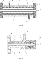
- Fig. 1 schematically shows a longitudinal section through a section of a jacketed pipe according to the prior art.
- An inner pipe 1 is surrounded by a jacket 2, so that there is an annular space 3 between the inner pipe 1 and the jacket 2.
- the jacket has an inlet 4 for a heat transfer fluid.
- the heat transfer fluid leaves the annular space 3 via an outlet, which is not shown in Fig. 1 .
- a press-on ring 8 was pressed onto the outer surface of the inner pipe.
- the jacket 2 was welded to the press-on ring 8.
- a flange was then attached to the inner pipe as a connecting element 6, for example by means of a thread or by pressing.
- the right-hand side of the pipe, which is not shown in Fig. 1 is manufactured in the same way.
- the space between the two connecting elements 6 is provided with insulation 7 made of an insulating material, e.g. glass wool or mineral wool.
- Fig. 2 schematically shows a longitudinal section through a first embodiment of a pipe component according to the invention.
- the pipe component comprises an inner pipe 1, a jacket 2 surrounding the inner pipe, an annular space 3 bounded by the outer surface of the inner pipe 1 and the inner surface of the jacket 2, as well as a connecting element 6 at each of the two pipe ends for connecting the pipe component to another component.
- the jacket 2 has an inlet 4 and an outlet 5 for a heat transfer fluid.
- the annular space 3 extends axially up to both connecting elements 6 and is bounded and sealed by these connecting elements.
- the connections between the two connecting elements 6, the inner pipe 1 and the jacket 2 were each made in an additive manufacturing process.
- FIG. 1 A comparison of Figs. 1 and 2 shows that, in contrast to the prior art, active temperature control of a process fluid flowing through the inner pipe 1 over the entire length of the pipe between the two connecting elements 6 is possible without interruption for the pipe component according to the invention.
- Fig. 3 shows a longitudinal section through a second embodiment according to the invention which prototypically demonstrates the possibilities of an individual adaptation of the pipe component to the respective requirements.
- the pipe component comprises an inner pipe 1 which is surrounded by a jacket 2 which has an inlet 4 for a heat transfer fluid.
- the pipe component On the left-hand side, the pipe component is bounded by a flange as connecting element 6, on the right-hand side, the connecting element is not shown.
- the flange has several openings for a screw connection, of which only one hole 12 can be seen in the sectional drawing.
- the inner diameter of the jacket 2 between the connecting element 6 and the inlet 4 is smaller than the inner diameter of the jacket 2 on the right-hand side after the inlet 4.
- the annular space 3 which is limited by the outer surface of the inner pipe 1 and the inner surface of the jacket 2, has different cross-sections.
- the annular space 3 extends into the connecting element 6, which also makes it possible to temper the connecting element, which is not possible with state-of-the-art pipe components.
- the outer surface of the inner pipe 1 varies in a wavelike manner in the axial direction. With a constant inner diameter of the inner pipe, the wall thickness of the inner pipe 1 varies in the axial direction accordingly.
- the inlet 4 for the heat transfer fluid is axially spaced from the connecting element 6.
- a deflecting element 9 is provided in the annular space 3, which directs part of the heat transfer fluid entering the annular space in the direction of the connecting element 6.
- the transition surface of inlet 4 into annulus 3 is curved.
- connecting elements 10 are provided which connect the inner pipe 1 and the jacket 2 and stabilize them against radial compressive loads. Furthermore, mixing elements 11 are located in this part of the annular space, which influence the flow of the heat transfer fluid and thus improve the heat transfer between the heat transfer fluid and the process fluid.
- the pipe component shown in Fig. 3 was completely manufactured in an additive manufacturing process.
Landscapes
- Engineering & Computer Science (AREA)
- General Engineering & Computer Science (AREA)
- Mechanical Engineering (AREA)
- Physics & Mathematics (AREA)
- Thermal Sciences (AREA)
- Chemical & Material Sciences (AREA)
- Manufacturing & Machinery (AREA)
- Materials Engineering (AREA)
- Rigid Pipes And Flexible Pipes (AREA)
Claims (13)
- Composant tuyau fait d'un matériau métallique, comprenant :un tuyau intérieur (1) ;une chemise (2) entourant le tuyau intérieur (1) ;un espace annulaire (3) limité par la surface extérieure du tuyau intérieur (1) et la surface intérieure de la chemise (2), la chemise (2) ayant au moins une entrée (4) et au moins une sortie (5) pour un fluide de transfert de chaleur ; etun élément de raccordement (6) au moins à une extrémité de tuyau pour raccorder le composant tuyau à un autre composant ;dans lequel l'espace annulaire (3) s'étend axialement jusqu'à l'élément de raccordement (6) et est limité et étanchéifié par l'élément de raccordement (6) ; etdans lequel le raccord entre l'élément de raccordement (6), le tuyau intérieur (1) et la chemise (2) est réalisé dans un procédé de fabrication additive ;caractérisé en ce que la surface de transition de l'entrée (4) à l'espace annulaire (3) et/ou la surface de transition de la sortie (5) à l'espace annulaire (3) est incurvée avec un rayon de 0,5 à 20 mm ou est chanfreinée avec une inclinaison de la surface de chanfrein de 20° à 80°.
- Composant tuyau selon la revendication 1, dans lequel la surface de transition est incurvée avec un rayon de 0,5 à 10 mm, de préférence avec un rayon de 0,5 à 6 mm.
- Composant tuyau selon la revendication 1, dans lequel la surface de transition est incurvée avec un rayon de 2 à 20 mm, de préférence avec un rayon de 2 à 10 mm, mieux encore avec un rayon de 2 à 6 mm.
- Composant tuyau selon l'une quelconque des revendications 1 à 3, dans lequel l'élément de raccordement (6) est une bride ou un élément pour le raccordement au moyen d'un joint de soudure.
- Composant tuyau selon l'une quelconque des revendications 1 à 4, dans lequel l'entrée (4) pour le fluide de transfert de chaleur est axialement espacée de l'élément de raccordement (6), et un élément déflecteur (9) est présent dans l'espace annulaire (3) qui dirige le fluide de transfert de chaleur entrant dans l'espace annulaire dans une direction définie à l'intérieur de l'espace annulaire.
- Composant tuyau selon la revendication 5, dans lequel l'élément déflecteur (9) conduit au moins une partie du fluide de transfert de chaleur entrant dans l'espace annulaire (3) vers l'élément de raccordement (6).
- Composant tuyau selon l'une quelconque des revendications 1 à 6, dans lequel un élément de raccordement respectif (6) est présent aux deux extrémités de tuyau, qui limite et étanchéifie l'espace annulaire (3), et dans lequel le raccord respectif entre l'élément de raccordement (6), le tuyau intérieur (1) et la chemise (2) est réalisé dans un procédé de fabrication additive.
- Composant tuyau selon l'une quelconque des revendications 1 à 7, dans lequel des éléments de jonction (10) sont présents dans l'espace annulaire (3), qui raccordent le tuyau intérieur (1) et la chemise (2) et sont conçus de manière telle qu'ils stabilisent le tuyau intérieur et la chemise contre des charges de pression radiales.
- Composant tuyau selon l'une quelconque des revendications 1 à 8, dans lequel des éléments mélangeurs (11) sont présents dans l'espace annulaire qui influencent l'écoulement du fluide de transfert de chaleur.
- Composant tuyau selon l'une quelconque des revendications 1 à 9, dans lequel l'épaisseur de paroi du tuyau intérieur (1) varie dans la direction axiale.
- Composant tuyau selon l'une quelconque des revendications 1 à 10, dans lequel le composant tuyau est complètement fabriqué dans un procédé de fabrication additive.
- Utilisation d'un composant tuyau selon l'une quelconque des revendications 1 à 11 dans un procédé à haute pression dans lequel la pression du fluide de procédé s'écoulant à travers le tuyau intérieur est supérieure à 100 bar, de préférence de 325 bar à 4000 bar.
- Utilisation d'un composant tuyau selon la revendication 12 dans un procédé pour la production de polyéthylène, de préférence de polyéthylène basse densité.
Applications Claiming Priority (2)
| Application Number | Priority Date | Filing Date | Title |
|---|---|---|---|
| EP18174889 | 2018-05-29 | ||
| PCT/EP2019/063114 WO2019228865A1 (fr) | 2018-05-29 | 2019-05-21 | Élément de tuyau fait d'un matériau métallique |
Publications (2)
| Publication Number | Publication Date |
|---|---|
| EP3803175A1 EP3803175A1 (fr) | 2021-04-14 |
| EP3803175B1 true EP3803175B1 (fr) | 2022-07-13 |
Family
ID=62486492
Family Applications (1)
| Application Number | Title | Priority Date | Filing Date |
|---|---|---|---|
| EP19725359.4A Active EP3803175B1 (fr) | 2018-05-29 | 2019-05-21 | Composant tubulaire d'un matériau métallique |
Country Status (3)
| Country | Link |
|---|---|
| EP (1) | EP3803175B1 (fr) |
| ES (1) | ES2928461T3 (fr) |
| WO (1) | WO2019228865A1 (fr) |
Families Citing this family (4)
| Publication number | Priority date | Publication date | Assignee | Title |
|---|---|---|---|---|
| CN112342527B (zh) * | 2020-09-11 | 2023-01-17 | 安徽贝意克设备技术有限公司 | 一种双向液态源蒸发cvd系统 |
| CN112797248B (zh) * | 2021-01-21 | 2023-02-28 | 郑州中原思蓝德高科股份有限公司 | 一种冷却输送装置 |
| CN113030165B (zh) * | 2021-03-09 | 2022-05-06 | 西安交通大学 | 一种高温气体等温壁面冷却实验矩形实验段 |
| FR3164267A1 (fr) * | 2024-07-04 | 2026-01-09 | Thales | Ensemble de double conduit avec gestion de fuite, procédés et produit-programme d'ordinateur associés |
Family Cites Families (3)
| Publication number | Priority date | Publication date | Assignee | Title |
|---|---|---|---|---|
| US5205969A (en) * | 1988-05-25 | 1993-04-27 | Signicast Corporation | Process for distributing a semi-solid wax to an injection press |
| EP2636691A1 (fr) * | 2012-03-07 | 2013-09-11 | Borealis AG | Procédé et installation pour la fabrication de polyéthylène-diène-copolymères |
| EP3290766B1 (fr) | 2016-09-01 | 2021-03-03 | Microtecnica S.r.l. | Système de contrôle environnemental d'un aéronef avec tuyau à double paroi et méthode |
-
2019
- 2019-05-21 EP EP19725359.4A patent/EP3803175B1/fr active Active
- 2019-05-21 WO PCT/EP2019/063114 patent/WO2019228865A1/fr not_active Ceased
- 2019-05-21 ES ES19725359T patent/ES2928461T3/es active Active
Also Published As
| Publication number | Publication date |
|---|---|
| WO2019228865A1 (fr) | 2019-12-05 |
| ES2928461T3 (es) | 2022-11-18 |
| EP3803175A1 (fr) | 2021-04-14 |
Similar Documents
| Publication | Publication Date | Title |
|---|---|---|
| EP3803175B1 (fr) | Composant tubulaire d'un matériau métallique | |
| KR102293634B1 (ko) | 유체 가열기, 유체 제어 장치, 및 유체 가열기의 제조 방법 | |
| EP0000497B1 (fr) | Conduit avec isolation interne en céramique pour le transport de fluides chauds | |
| US20170197196A1 (en) | Exchanger and/or reactor-exchanger manufactured in an additive process | |
| CN101783191B (zh) | 核电站用超级管道及其制造方法 | |
| EP2278248B1 (fr) | Echangeur thermique destiné au refroidissement de gaz de craquage | |
| KR20150107675A (ko) | 고온 용례용 파이프 연결부들을 용접하는 프로세스 | |
| JP2018501111A (ja) | 流体導管要素及び流体導管要素を製造するための方法 | |
| EP2837809B1 (fr) | Tête de cylindre d'un moteur à combustion interne et procédé de fabrication d'une tête de cylindre d'un moteur à combustion interne | |
| US20240424565A1 (en) | Method for producing a component, and correspondingly produced component | |
| EP0527268A1 (fr) | Méthode de fabrication d'un tuyau composé | |
| EP1537921B1 (fr) | Méthode de fabrication d'un tube multicouche pour le guidage des fluides de transfer de chaleur et tube multicouche | |
| EP3665413B1 (fr) | Procédé de gainage de la partie intérieure d'une partie constitutive d'un récipient sous pression et dispositif de fusion d'un revêtement sur celui-ci | |
| CN111001960A (zh) | 扬克缸缸段预加工件以及用于制造扬克缸的方法 | |
| JP6528098B2 (ja) | ロケット用再生冷却燃焼室の製造方法及びロケット用再生冷却燃焼室 | |
| US12455022B2 (en) | Connection element | |
| US6799418B2 (en) | Rocket engine member and method for manufacturing a rocket engine member | |
| US20180200690A1 (en) | Heat exchanger and/or heat exchanger-reactor including channels having thin walls between one another | |
| US20240175644A1 (en) | Method for producing pipes having topographic inner structures | |
| CN114929375B (zh) | 用于热壁脱氢反应器的热学套 | |
| CN106123669B (zh) | 构成能集成到热交换器的复合材料制热交换器模块的块件 | |
| KR20220100072A (ko) | 다양한 비틀림 각도를 가진 열교환기 구성요소 | |
| US20190376685A1 (en) | Desuperheater and spray nozzles therefor | |
| US12583052B2 (en) | Method for connecting ferritic with austenitic steel pipes | |
| JPH11309587A (ja) | 金属管の突合せ接合方法および装置 |
Legal Events
| Date | Code | Title | Description |
|---|---|---|---|
| STAA | Information on the status of an ep patent application or granted ep patent |
Free format text: STATUS: UNKNOWN |
|
| STAA | Information on the status of an ep patent application or granted ep patent |
Free format text: STATUS: THE INTERNATIONAL PUBLICATION HAS BEEN MADE |
|
| PUAI | Public reference made under article 153(3) epc to a published international application that has entered the european phase |
Free format text: ORIGINAL CODE: 0009012 |
|
| STAA | Information on the status of an ep patent application or granted ep patent |
Free format text: STATUS: REQUEST FOR EXAMINATION WAS MADE |
|
| 17P | Request for examination filed |
Effective date: 20210111 |
|
| AK | Designated contracting states |
Kind code of ref document: A1 Designated state(s): AL AT BE BG CH CY CZ DE DK EE ES FI FR GB GR HR HU IE IS IT LI LT LU LV MC MK MT NL NO PL PT RO RS SE SI SK SM TR |
|
| AX | Request for extension of the european patent |
Extension state: BA ME |
|
| DAV | Request for validation of the european patent (deleted) | ||
| DAX | Request for extension of the european patent (deleted) | ||
| GRAP | Despatch of communication of intention to grant a patent |
Free format text: ORIGINAL CODE: EPIDOSNIGR1 |
|
| STAA | Information on the status of an ep patent application or granted ep patent |
Free format text: STATUS: GRANT OF PATENT IS INTENDED |
|
| RIC1 | Information provided on ipc code assigned before grant |
Ipc: F28F 9/22 20060101ALI20220114BHEP Ipc: F28D 21/00 20060101ALI20220114BHEP Ipc: F28D 7/10 20060101ALI20220114BHEP Ipc: B33Y 80/00 20150101ALI20220114BHEP Ipc: F16L 53/32 20180101ALI20220114BHEP Ipc: F16L 53/70 20180101ALI20220114BHEP Ipc: F16L 9/18 20060101AFI20220114BHEP |
|
| INTG | Intention to grant announced |
Effective date: 20220204 |
|
| GRAS | Grant fee paid |
Free format text: ORIGINAL CODE: EPIDOSNIGR3 |
|
| GRAA | (expected) grant |
Free format text: ORIGINAL CODE: 0009210 |
|
| STAA | Information on the status of an ep patent application or granted ep patent |
Free format text: STATUS: THE PATENT HAS BEEN GRANTED |
|
| AK | Designated contracting states |
Kind code of ref document: B1 Designated state(s): AL AT BE BG CH CY CZ DE DK EE ES FI FR GB GR HR HU IE IS IT LI LT LU LV MC MK MT NL NO PL PT RO RS SE SI SK SM TR |
|
| REG | Reference to a national code |
Ref country code: CH Ref legal event code: EP |
|
| REG | Reference to a national code |
Ref country code: DE Ref legal event code: R096 Ref document number: 602019016992 Country of ref document: DE |
|
| REG | Reference to a national code |
Ref country code: AT Ref legal event code: REF Ref document number: 1504453 Country of ref document: AT Kind code of ref document: T Effective date: 20220815 |
|
| REG | Reference to a national code |
Ref country code: IE Ref legal event code: FG4D |
|
| REG | Reference to a national code |
Ref country code: NL Ref legal event code: FP |
|
| REG | Reference to a national code |
Ref country code: LT Ref legal event code: MG9D |
|
| REG | Reference to a national code |
Ref country code: ES Ref legal event code: FG2A Ref document number: 2928461 Country of ref document: ES Kind code of ref document: T3 Effective date: 20221118 |
|
| PG25 | Lapsed in a contracting state [announced via postgrant information from national office to epo] |
Ref country code: SE Free format text: LAPSE BECAUSE OF FAILURE TO SUBMIT A TRANSLATION OF THE DESCRIPTION OR TO PAY THE FEE WITHIN THE PRESCRIBED TIME-LIMIT Effective date: 20220713 Ref country code: RS Free format text: LAPSE BECAUSE OF FAILURE TO SUBMIT A TRANSLATION OF THE DESCRIPTION OR TO PAY THE FEE WITHIN THE PRESCRIBED TIME-LIMIT Effective date: 20220713 Ref country code: PT Free format text: LAPSE BECAUSE OF FAILURE TO SUBMIT A TRANSLATION OF THE DESCRIPTION OR TO PAY THE FEE WITHIN THE PRESCRIBED TIME-LIMIT Effective date: 20221114 Ref country code: NO Free format text: LAPSE BECAUSE OF FAILURE TO SUBMIT A TRANSLATION OF THE DESCRIPTION OR TO PAY THE FEE WITHIN THE PRESCRIBED TIME-LIMIT Effective date: 20221013 Ref country code: LV Free format text: LAPSE BECAUSE OF FAILURE TO SUBMIT A TRANSLATION OF THE DESCRIPTION OR TO PAY THE FEE WITHIN THE PRESCRIBED TIME-LIMIT Effective date: 20220713 Ref country code: LT Free format text: LAPSE BECAUSE OF FAILURE TO SUBMIT A TRANSLATION OF THE DESCRIPTION OR TO PAY THE FEE WITHIN THE PRESCRIBED TIME-LIMIT Effective date: 20220713 Ref country code: FI Free format text: LAPSE BECAUSE OF FAILURE TO SUBMIT A TRANSLATION OF THE DESCRIPTION OR TO PAY THE FEE WITHIN THE PRESCRIBED TIME-LIMIT Effective date: 20220713 |
|
| PG25 | Lapsed in a contracting state [announced via postgrant information from national office to epo] |
Ref country code: PL Free format text: LAPSE BECAUSE OF FAILURE TO SUBMIT A TRANSLATION OF THE DESCRIPTION OR TO PAY THE FEE WITHIN THE PRESCRIBED TIME-LIMIT Effective date: 20220713 Ref country code: IS Free format text: LAPSE BECAUSE OF FAILURE TO SUBMIT A TRANSLATION OF THE DESCRIPTION OR TO PAY THE FEE WITHIN THE PRESCRIBED TIME-LIMIT Effective date: 20221113 Ref country code: HR Free format text: LAPSE BECAUSE OF FAILURE TO SUBMIT A TRANSLATION OF THE DESCRIPTION OR TO PAY THE FEE WITHIN THE PRESCRIBED TIME-LIMIT Effective date: 20220713 Ref country code: GR Free format text: LAPSE BECAUSE OF FAILURE TO SUBMIT A TRANSLATION OF THE DESCRIPTION OR TO PAY THE FEE WITHIN THE PRESCRIBED TIME-LIMIT Effective date: 20221014 |
|
| REG | Reference to a national code |
Ref country code: DE Ref legal event code: R097 Ref document number: 602019016992 Country of ref document: DE |
|
| PG25 | Lapsed in a contracting state [announced via postgrant information from national office to epo] |
Ref country code: SM Free format text: LAPSE BECAUSE OF FAILURE TO SUBMIT A TRANSLATION OF THE DESCRIPTION OR TO PAY THE FEE WITHIN THE PRESCRIBED TIME-LIMIT Effective date: 20220713 Ref country code: RO Free format text: LAPSE BECAUSE OF FAILURE TO SUBMIT A TRANSLATION OF THE DESCRIPTION OR TO PAY THE FEE WITHIN THE PRESCRIBED TIME-LIMIT Effective date: 20220713 Ref country code: DK Free format text: LAPSE BECAUSE OF FAILURE TO SUBMIT A TRANSLATION OF THE DESCRIPTION OR TO PAY THE FEE WITHIN THE PRESCRIBED TIME-LIMIT Effective date: 20220713 Ref country code: CZ Free format text: LAPSE BECAUSE OF FAILURE TO SUBMIT A TRANSLATION OF THE DESCRIPTION OR TO PAY THE FEE WITHIN THE PRESCRIBED TIME-LIMIT Effective date: 20220713 |
|
| PLBE | No opposition filed within time limit |
Free format text: ORIGINAL CODE: 0009261 |
|
| STAA | Information on the status of an ep patent application or granted ep patent |
Free format text: STATUS: NO OPPOSITION FILED WITHIN TIME LIMIT |
|
| PG25 | Lapsed in a contracting state [announced via postgrant information from national office to epo] |
Ref country code: SK Free format text: LAPSE BECAUSE OF FAILURE TO SUBMIT A TRANSLATION OF THE DESCRIPTION OR TO PAY THE FEE WITHIN THE PRESCRIBED TIME-LIMIT Effective date: 20220713 Ref country code: EE Free format text: LAPSE BECAUSE OF FAILURE TO SUBMIT A TRANSLATION OF THE DESCRIPTION OR TO PAY THE FEE WITHIN THE PRESCRIBED TIME-LIMIT Effective date: 20220713 |
|
| 26N | No opposition filed |
Effective date: 20230414 |
|
| PG25 | Lapsed in a contracting state [announced via postgrant information from national office to epo] |
Ref country code: AL Free format text: LAPSE BECAUSE OF FAILURE TO SUBMIT A TRANSLATION OF THE DESCRIPTION OR TO PAY THE FEE WITHIN THE PRESCRIBED TIME-LIMIT Effective date: 20220713 |
|
| REG | Reference to a national code |
Ref country code: AT Ref legal event code: UEP Ref document number: 1504453 Country of ref document: AT Kind code of ref document: T Effective date: 20220713 |
|
| PG25 | Lapsed in a contracting state [announced via postgrant information from national office to epo] |
Ref country code: SI Free format text: LAPSE BECAUSE OF FAILURE TO SUBMIT A TRANSLATION OF THE DESCRIPTION OR TO PAY THE FEE WITHIN THE PRESCRIBED TIME-LIMIT Effective date: 20220713 |
|
| REG | Reference to a national code |
Ref country code: CH Ref legal event code: PL |
|
| PG25 | Lapsed in a contracting state [announced via postgrant information from national office to epo] |
Ref country code: MC Free format text: LAPSE BECAUSE OF FAILURE TO SUBMIT A TRANSLATION OF THE DESCRIPTION OR TO PAY THE FEE WITHIN THE PRESCRIBED TIME-LIMIT Effective date: 20220713 |
|
| PG25 | Lapsed in a contracting state [announced via postgrant information from national office to epo] |
Ref country code: MC Free format text: LAPSE BECAUSE OF FAILURE TO SUBMIT A TRANSLATION OF THE DESCRIPTION OR TO PAY THE FEE WITHIN THE PRESCRIBED TIME-LIMIT Effective date: 20220713 Ref country code: LU Free format text: LAPSE BECAUSE OF NON-PAYMENT OF DUE FEES Effective date: 20230521 Ref country code: LI Free format text: LAPSE BECAUSE OF NON-PAYMENT OF DUE FEES Effective date: 20230531 Ref country code: CH Free format text: LAPSE BECAUSE OF NON-PAYMENT OF DUE FEES Effective date: 20230531 |
|
| REG | Reference to a national code |
Ref country code: IE Ref legal event code: MM4A |
|
| PG25 | Lapsed in a contracting state [announced via postgrant information from national office to epo] |
Ref country code: IE Free format text: LAPSE BECAUSE OF NON-PAYMENT OF DUE FEES Effective date: 20230521 |
|
| PG25 | Lapsed in a contracting state [announced via postgrant information from national office to epo] |
Ref country code: IE Free format text: LAPSE BECAUSE OF NON-PAYMENT OF DUE FEES Effective date: 20230521 |
|
| PG25 | Lapsed in a contracting state [announced via postgrant information from national office to epo] |
Ref country code: BG Free format text: LAPSE BECAUSE OF FAILURE TO SUBMIT A TRANSLATION OF THE DESCRIPTION OR TO PAY THE FEE WITHIN THE PRESCRIBED TIME-LIMIT Effective date: 20220713 |
|
| PG25 | Lapsed in a contracting state [announced via postgrant information from national office to epo] |
Ref country code: BG Free format text: LAPSE BECAUSE OF FAILURE TO SUBMIT A TRANSLATION OF THE DESCRIPTION OR TO PAY THE FEE WITHIN THE PRESCRIBED TIME-LIMIT Effective date: 20220713 |
|
| PGFP | Annual fee paid to national office [announced via postgrant information from national office to epo] |
Ref country code: NL Payment date: 20250526 Year of fee payment: 7 |
|
| PGFP | Annual fee paid to national office [announced via postgrant information from national office to epo] |
Ref country code: DE Payment date: 20250528 Year of fee payment: 7 |
|
| PGFP | Annual fee paid to national office [announced via postgrant information from national office to epo] |
Ref country code: ES Payment date: 20250612 Year of fee payment: 7 |
|
| PGFP | Annual fee paid to national office [announced via postgrant information from national office to epo] |
Ref country code: BE Payment date: 20250526 Year of fee payment: 7 Ref country code: IT Payment date: 20250522 Year of fee payment: 7 |
|
| PGFP | Annual fee paid to national office [announced via postgrant information from national office to epo] |
Ref country code: FR Payment date: 20250526 Year of fee payment: 7 |
|
| PGFP | Annual fee paid to national office [announced via postgrant information from national office to epo] |
Ref country code: AT Payment date: 20250520 Year of fee payment: 7 |
|
| PG25 | Lapsed in a contracting state [announced via postgrant information from national office to epo] |
Ref country code: CY Free format text: LAPSE BECAUSE OF FAILURE TO SUBMIT A TRANSLATION OF THE DESCRIPTION OR TO PAY THE FEE WITHIN THE PRESCRIBED TIME-LIMIT; INVALID AB INITIO Effective date: 20190521 |
|
| PG25 | Lapsed in a contracting state [announced via postgrant information from national office to epo] |
Ref country code: HU Free format text: LAPSE BECAUSE OF FAILURE TO SUBMIT A TRANSLATION OF THE DESCRIPTION OR TO PAY THE FEE WITHIN THE PRESCRIBED TIME-LIMIT; INVALID AB INITIO Effective date: 20190521 |
|
| PG25 | Lapsed in a contracting state [announced via postgrant information from national office to epo] |
Ref country code: TR Free format text: LAPSE BECAUSE OF FAILURE TO SUBMIT A TRANSLATION OF THE DESCRIPTION OR TO PAY THE FEE WITHIN THE PRESCRIBED TIME-LIMIT Effective date: 20220713 |
|
| PGFP | Annual fee paid to national office [announced via postgrant information from national office to epo] |
Ref country code: GB Payment date: 20260304 Year of fee payment: 8 |