EP3803302B9 - Bande de détection de température - Google Patents
Bande de détection de température Download PDFInfo
- Publication number
- EP3803302B9 EP3803302B9 EP19737900.1A EP19737900A EP3803302B9 EP 3803302 B9 EP3803302 B9 EP 3803302B9 EP 19737900 A EP19737900 A EP 19737900A EP 3803302 B9 EP3803302 B9 EP 3803302B9
- Authority
- EP
- European Patent Office
- Prior art keywords
- tape
- electric
- temperature sensing
- support layer
- temperature
- Prior art date
- Legal status (The legal status is an assumption and is not a legal conclusion. Google has not performed a legal analysis and makes no representation as to the accuracy of the status listed.)
- Active
Links
Images


Classifications
-
- G—PHYSICS
- G01—MEASURING; TESTING
- G01K—MEASURING TEMPERATURE; MEASURING QUANTITY OF HEAT; THERMALLY-SENSITIVE ELEMENTS NOT OTHERWISE PROVIDED FOR
- G01K3/00—Thermometers giving results other than momentary value of temperature
- G01K3/005—Circuits arrangements for indicating a predetermined temperature
Definitions
- the present invention relates to a temperature sensing tape, a system for determining the presence and/or the position of a thermal variation indicative of an overheating localized on a surface and to the operating method thereof.
- the present invention further relates to a system for determining the presence and/or the position of a thermal variation indicative of an overcooling/freezing localized on a surface and to the operating method thereof.
- the present invention concerns determination of the presence and the position of surface thermal variations caused by conditions of surface overheating or overcooling/freezing preferably in a building, for example the roof or other parts of the building itself; to which the following discussion will explicitly refer without loss of generality.
- the need to be able to locate surfaces of a building is also known, for example of a roof or of a floor, pipes, in which a condition of freezing/formation of ice occurs.
- the application CA 2 203 447 concerns a control system to display, by means of a panel, overtemperature conditions in the wings of an aircraft.
- the system comprises overheating detection devices permanently installed in the wings.
- Each overheating detector device comprises a loop-shaped supply line for connection to the panel terminals and a series of resistors arranged in series in a loop on the supply line.
- the object of the present invention is to provide an inexpensive and robust system which is easy and simple to install and which is able to satisfy the above needs.
- the present invention also relates to a system produced according to the attached claims, which determines through at least a temperature sensing tape, the presence and the position of a pre-set thermal variation on a surface in which said variation is indicative of an overheating or an overcooling/freezing of the surface.
- the present invention further relates to a method that determines, through at least one temperature sensing tape, the presence and the position of a pre-set thermal variation on a surface caused by overheating or overcooling/freezing, as defined in the attached claims.
- the number 1 designates overall a system for determining the presence and/or the position of a temperature variation indicative preferably of an overheating in an area/surface of a building.
- the system 1 is configured to determine the presence and the position of the temperature variation preferably indicative of the overheating in areas/surfaces of a building which are part of the roof 2 of the building.
- the roof 2 can be preferably provided with an insulation system 3 and at least a covering M in flat/curved tiles arranged above the insulation system 3 so as to cover it.
- the present invention is not limited to determination of the presence and position of an overheating of a surface, but according to a possible embodiment variation can be applied to determine the position of a surface in which a condition of overcooling/freezing occurs.
- the present invention should not be considered limited to detecting the state of localized overheating or overcooling/freezing of the roof and/or of a specific area of the roof, for example corresponding to the insulation system, but may be used, on the basis of the following description, to detect the presence and the position of an overheating or overcooling/freezing on any other area/surface of the building or component parts thereof.
- the system 1 comprises one or more high-flexibility thin temperature sensing tapes 4, each of which has an elongated shape, preferably rectangular, extends along a longitudinal axis A and is designed to be arranged with its lower largest surface resting on the surface of the roof 2, for example on an upper surface portion of the floor 3.
- the temperature sensing tapes 4 are preferably easy to cut transversal to the longitudinal axis A along their entire width, and may be arranged on the roof 2, preferably side-by-side and parallel to one another, at pre-set distances from one another.
- the temperature sensing tapes 4 are preferably arranged resting on the surface so as to be installed and easily separated/removed from the same.
- Figure 1 shows an X-Y Cartesian reference system arranged roughly coplanar with the surface of the roof 2 to be monitored in which the X axis (abscissa) is parallel to the axes A of the temperature sensing tapes 4, and the Y axis (ordinate) is orthogonal to the same.
- each temperature sensing tape 4 can comprise: at least one support layer 5 made of flexible material, easy to cut transversally, and electrically insulating, and an electric measurement circuit.
- the support layer 5 is structured to support the electric measurement circuit.
- the electric measurement circuit comprises at least two electric wires 6.
- the support layer 5 is made by means of a high flexibility (high pliability) thin plastic film.
- the high flexibility of the support layer 5 allows, on the one hand, the temperature sensing tape 4 to be rolled up, thus conveniently obtaining a roll that is designed adapted to be transported manually, especially on a roof, and simplifies manual application of the temperature sensing tape 4 on the surface to be monitored ( Figure 2 ).
- the support layer 5 can be made of any high-flexibility material such as, for example, rubber, plastic, paper, fabric or similar materials.
- a particularly suitable film for producing the temperature sensing tape 4 may be based on polyimide.
- the film could be made of a composite material, preferably FR4 or similar.
- a particularly suitable support layer 5 may be obtained by means of a thin KAPTON ® -based film.
- the width of the temperature sensing tape 4 may expediently range from approximately 10 mm to approximately 25 mm.
- the thickness of the support layer 5 may range from 50 micron to 350 micron. It is understood, however, that the support layer 5 is structured/sized so as to guarantee a relatively high robustness, necessary for the specific building application in question.
- the wires 6 are made of electrically conductive material, for example copper or aluminium or similar, they are side-by-side and spaced from one another at a pre-set distance, and extend along the temperature sensing tape 4 parallel to said longitudinal axis A.
- the wires 6 can be filiform and about rectilinear. It is understood, however, that the wires 6 could be plate-like (flat cables) and/or have any similar shape suited to the purpose of the present invention.
- the electric measurement circuit of the temperature sensing tape 4 further comprises a plurality of resistors 7, which are arranged along at least one of the wires 6, connected in series to one another, at pre-set distances from one another (measured along the X axis) and have respective pre-set resistances.
- the reciprocal distance between the electric resistors 7 along the axis A depends on the resolution of the desired temperature monitoring and/or on the length of the temperature sensing tape 4.
- the distance between one resistor 7 and the other resistor 7 along the temperature sensing tape 4 may be between approximately 20 cm and approximately 70 cm, preferably approximately 50 cm.
- the electric measurement circuit of the temperature sensing tape 4 further comprises a plurality of thermally actuated electric devices 50, each of which is connected between the two wires 6 at a resistor 7 and is designed, in use, to be actuated based on the temperature to vary the electric resistance of the temperature sensing tape 4 based on the position of the actuated electric device 50.
- the thermally actuated electric devices 50 can comprise thermally actuated switch modules configured to switch from an open state to a closed state when the temperature present on the tape at the switch modules reaches a pre-set temperature threshold.
- the pre-set temperature threshold can be associated with a critical high temperature, which is indicative of a condition of overheating.
- the pre-set temperature threshold may correspond to a critical low temperature (for example lower than 0°C) indicative of the condition of overcooling/freezing.
- the thermally actuated electric devices 50 may be configured so as to switch to closing when the temperature at the electric device 50 reaches the low temperature.
- measurement of the resistance of the tape is carried out as described below and thus allows determination of the position of the closed thermocontact along the tape 4 and therefore indication of the condition of overcooling /freezing which can be indicative, for example, of the presence of ice on the tape and therefore on the surface below.
- the electric devices 50 may comprise thermocontacts or thermo-switches or other similar temperature-dependent switches, and each have a terminal connected to the second wire and the other terminal connected to the terminal downstream of a relative resistor 7. It is understood that the electric devices 50 may comprise any temperature-dependent switch provided with an electric, electronic, electromechanical or similar circuit/device.
- thermocontact When the temperature threshold is reached at the thermocontact, the latter closes.
- the thermocontact thus connects the two electric wires 6 at a resistor 7 determining a resistance variation of the tape which in this case corresponds to the sum of the resistances of the resistors positioned upstream of the closed thermocontact.
- the measurement of the resistance thus allows determination of the position of the closed thermocontact along the tape and indication of the overheating.
- thermocontact corresponds to the low temperature
- measurement of the resistance allows determination of the position of the closed thermocontact along the tape and consequently determination of the coordinate of the overcooling/freezing relative to the X axis.
- the wires 6, and/or the resistors 7 and/or the electric devices 50 can be embedded/enclosed in the support layer 5.
- the support layer 5 can be made of waterproof material.
- the electrically actuated electric devices 50 can comprise thermoresistors.
- the thermoresistors can be PTC (Positive Temperature Coefficient) resistors or NTC (Negative Temperature Coefficient) resistors.
- the temperature variation of the tape 4 at the thermoresistor determines a corresponding resistance variation of the tape associated with the position of the thermoresistor.
- the position of the thermoresistor that has undergone the resistance variation is indicative of the axial position (X) of the thermal variation along the tape 4.
- thermoresistor can be configured so as to considerably reduce its resistance when the temperature reaches the pre-set threshold. In this condition the thermoresistor goes to a state in which it operates similarly to a switch that connects the two electric wires determining a resistance variation of the tape.
- the resistance of the tape corresponds roughly to the sum of the resistances of the resistors positioned upstream of the operative thermoresistor, and the system is therefore able to determine, based on the resistance, the position of the latter and therefore the position of the thermal variation caused by the overheating.
- the temperature sensing tape 4 can comprise an adhesive layer 9 adapted to permanently fix the temperature sensing tape 4 on the floor 3 of the roof 2 to be monitored.
- the Applicant has found, for example, that it could be expedient to use a band-shaped removable film 9a which covers the adhesive layer 9 and which in use is separated from the temperature sensing tape 4 to allow fixing of the temperature sensing tape 4 on the roof 2.
- the manufacture and/or fixing of the wires 6 and the resistors 7 on the support layer 5 can be carried out by means of any assembly process such as, for example, by deposition, photolithography, plasma, printing with electrostatic adhesives, and using conductive inks or pastes, graphite, etc.
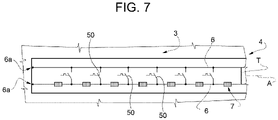
- the temperature sensing tape 4 has at an axial end two terminals 6a connected to the two corresponding two wires 6.
- the terminal 6a consists of an end of a wire 6 present at an end of the sensing tape 4.
- the terminal 6a can be expediently obtained by cutting the tape 4 at preferential cutting points.
- the surface of the tape 4 can be expediently provided with notches 4K, for example moulded at pre-set distances from one another and relative to the electric components 7, indicative of the preferential cutting points. In this way, an indication is given to the installer on the point at which to cut the tape 4 to obtain the terminals 6a, preventing damage to the resistors 7 and the electric components 50.
- the terminal 6a can comprise a pad P made of electric conductive material, for example copper or similar, shaped to facilitate the electric connection with electric terminals/connectors or similar.
- the pads P can be arranged on/in the layer 5 of the tape 4 along the wires 6 at the notches 4K. In use, execution of the cut of the tape 4 roughly transversally to the longitudinal axis A at the notches 4K allows the pads P to be obtained on the cut longitudinal end of the tape 4 thus forming the terminals 6a.
- the system 1 can comprise a plurality of temperature sensing tapes 4.
- the temperature sensing tapes 4 can be arranged on the surface of the roof 2, substantially side-by-side, parallel to one another, each with its own end, containing the two terminals 6a in a pre-set position relative to the Y axis.
- the system 1 further comprises a plurality of electronic modules 8 which are electrically connected to the respective temperature sensing tapes 4.
- the electric connection between the electronic module 8 and the relative temperature sensing tape 4 can be provided for example by means of electric connectors/terminals (not illustrated).
- the cut end of the tape 4 can be expediently inserted into the electric connectors/terminals of the electronic module 8.
- Closing of the terminal screws provides the electric contact of the electric measurement module 8 with the pads P defining the terminals 6a.
- each electric measurement module 8 can be configured so as to determine the electric resistance between the two terminals 6a.
- the system 1 can further comprise an electronic device 10 which is electrically connected to the electronic modules 8 to receive the resistances measured/determined by the same.
- the electronic modules 8 can be connected through respective terminals to a common data/signal exchange bus/line connected in turn to a data/signal processing module 11 of the electronic device 10.
- the electronic modules 8 can furthermore be connected, preferably through respective terminals, to a common electric power supply bus/line connected in turn to an electric power supply device 12 of the electronic device 10.
- the electronic modules 8 can be connected along the electric line and along the data line in cascade one after the other.
- the two common power supply and data/signal exchange electric lines can be formed of sections of connection lines between the adjacent electronic modules 8 as shown in the example of Figure 1 .
- the data/signal processing module 11 of the electronic device 10 can be configured so as to receive for each temperature sensing tape 4 the relative resistance and determine the presence and/or the position of the overheating along the temperature sensing tape 4 based on the determined resistance.
- the resistance variation is generated by the closing of an electric device 50 in response to the overheating of the tape 4 at the area surrounding the electric device 50.
- the pre-set position of the temperature sensing tape 4 on the roof 2 along the Y axis allows information to be obtained on the position of the overheated area relative to the second Y axis.
- the electronic device 10 can further comprise an electronic communication stage 13 configured to communicate data from and to systems 15 and/or remote communication devices 16.
- the communication between the electronic device 10 and the systems 15 and/or remote communication devices 16 can be obtained by means of a communication device 18 arranged for example in a central electronic control unit 19.
- the central electronic control unit 19 can be a domestic electric control unit provided with a processing unit 21 which centrally supervises the system 1 and preferably, but not necessarily, other domotic/detection systems (not illustrated) present in the building.
- the local communication device 18 can comprise a communication module able to establish communication between one or more communication networks.
- the communication module can comprise a gateway which carries out a short-range communication to communicate with the electronic communication stage 13 by means of, for example, a domestic communication network.
- the gateway can furthermore carry out a long-range communication and operate for example according to LoRa technology to communicate with an internet/telephone network thus transmitting data to the systems 15 and/or to the remote communication devices 16.
- the electronic communication stage 13 it can comprise, for example, a wireless data transmission module (Wi-Fi, Wireless, Bluetooth). It is understood, however, that the electronic communication stage 13 could comprise a wired data/signal transmission module.
- the systems 15 can comprise cloud computing systems or similar.
- the remote communication devices 16 can comprise mobile user communication devices, for example smartphones or similar.
- the central electronic control unit 19 can be configured so as to determine the presence and position of the overheating in an area based on the resistance, and provide the same in the form of information/data and/or generate alarm signals indicative of the overheating/danger.
- the tape 4 can be arranged at the floor 3 of the roof 2 close to the flue (not illustrated) and the central electronic control unit 19 can be configured to detect the presence and position of the overheating and provide the systems 15 and/or the devices 16 with alarm messages/signals indicative of a condition of danger of overheating/fire of the roof/flue.
- the tape 4 may be arranged on a surface of a floor to detect the thermal variation associated with the overcooling/freezing of the same.
- the tape 4 may be arranged on a surface adjacent to a skylight, to detect the thermal variation associated with overheating of the same.
- the tape 4 can be arranged on the roof 2 close to the upper surface of solar/photovoltaic panels (not illustrated), and the central electronic control unit 19 can be configured to determine a condition of localized overheating of said panels to provide the systems 15 and/or the devices 16 with alarm messages/signals indicative of a condition of request for maintenance of/intervention on said panels.
- the system 1 comprises a plurality of temperature sensing tapes 4 arranged on the surface to be monitored.
- the temperature sensing tapes 4 are arranged on a surface which, in the example illustrated in Figure 1 , corresponds for example to the floor 3 ( Figure 1 ).
- the central electronic control unit 19 can be configured to detect localized overheating to provide the systems 15 and/or the devices 16 with alarm data/messages/signals indicative of a condition of request for maintenance of the floor 3/roof 2 and the relative critical positions subject to overheating.
- the system is able to signal the exact position of the area/areas of the roof along the axis (Y) in which the intervention is requested since it corresponds/they correspond to the area/areas covered by the tape/tapes 4.
- the data/messages/signals and/or data indicative of the presence and position of the overheating (overcooling) can be expediently displayed to a user through the mobile communication device 16.
- a graphic thermal map can be generated indicative of the distribution of the overheated (or overcooled) areas, detected through the temperature sensing tapes 4, with display of the same.
- the operation of the system 1 entails measurement of the resistances of the electric measurement circuits of one or more temperature sensing tapes 4 arranged on the surface to be monitored, determination of the presence and position of the overheating area of the surface monitored along the X axis and the Y axis based on the resistance measured, and generation of the signals/data/messages indicative of the presence and position coordinates (X,Y) of the overheating detected on the surface towards the system 15 and/or the devices 16.
- the electronic device 10 associated with each tape 4 can transmit via the electronic communication stage 13 of the central electronic control unit 19 the signals/data/messages containing the presence and the position of the overheating on the surface to the cloud systems and/or to at least one communication device 16.
- the system 1 can provide for measurement of the resistances of the electric measurement circuits of one or more temperature sensing tapes 4 arranged on the surface to be monitored, determination of the presence and position of the overcooling/freezing area of the surface monitored along the X axis and the Y axis based on the resistance measured, and generation of the signals/data/messages indicative of the presence and position coordinates (X,Y) of the overcooling/freezing detected on the surface towards the system 15 and/or the devices 16.
- the electronic device 10 associated with each tape 4 can transmit via the electronic communication stage 13 of the central electronic control unit 19 the signals/data/messages containing the presence and the position of the overcooling/freezing on the surface to the cloud systems and/or to at least a communication device 16.
- the temperature sensing tape can be easily adapted lengthwise to the dimensions of the surface. For this purpose, it can be cut by the installer without causing malfunctioning of the system.
- an overheating detection device described in the application CA 2 203 447 is not suitable for mounting on a roof, or on a skirting board or on a panel, since it cannot be adapted each time to the dimensions of the same.
- a transverse cut would in fact determine interruption of the U connection lines of the switches.
- the longitudinal dimension of the tape described above (length) can be easily varied/adapted each time through a simple transverse cut, according to requirements, in particular based on the dimensions of the object on which it is installed, with all the resulting advantages.
- the data relative to the overheated (or frozen) areas detected by the system can be used for statistical purposes, for evaluation of the insulation quality.
- the system can also be used by other domotic systems present in the building such as, for example, roof cooling systems with the use of water and/or radiation data for solar/photovoltaic panels, since it is able to provide an alarm linked to the fact that the panel surface is dirty and does not reach the scheduled thermal power with the same radiation.
- FIG. 6 The embodiment illustrated in Figure 6 is relative to a system 40, which is similar to the system 1 shown in Figure 1 and the component parts of which will be designated, where possible, by the same reference numbers as those that designates corresponding parts of the system 1.
- the system 40 differs from the system 1 shown in Figure 1 due to the fact that, in addition to comprising the flexible sensing tapes 4, it comprises a main flexible tape 41, which internally contains the electronic modules 8 and preferably the processing device 10 and the relative electric connections (described above for the system 1).
- the main tape 41 preferably has the same structure and material as the sensing tapes 4.
- the main tape 41 comprises a layer identical to the layer 5 described above, and can preferably comprise the adhesive layer 9 and the relative film 9a.
- the electronic modules 8 are enclosed/embedded in said support layer 5 of the main tape 41 so as to be covered by the same.
- the main tape 41 can be arranged in a direction parallel to the Y axis, at the ends of the temperature sensing tapes 4 so as to be roughly orthogonal to the same.
- the system 40 can further be provided with lateral connection sections 42 which extend cantilever from the same side of the main tape 41, orthogonal to the same, at the electric module 8 and internally contain, connection wires and/or connection terminals of the electronic module 8.
- the system 40 can further comprise junction terminals 43 adapted to electrically connect the connection wires or connection terminals of the lateral sections 42 to the electric terminals of the wires 6 of the temperature sensing tapes 4.
- the processing device 10 can be embedded in a lower end of the main tape 41 and have an adjacent lateral section 42 for connection between the latter and a sensing tape 4.
Landscapes
- Physics & Mathematics (AREA)
- General Physics & Mathematics (AREA)
- Fire-Detection Mechanisms (AREA)
- Organic Insulating Materials (AREA)
- Cable Accessories (AREA)
Claims (20)
- Bande de détection de température (4) qui est structurée pour être disposée en appui sur une surface d'un bâtiment,ladite bande de détection de température comprenantune couche de support mince (5) ayant une forme allongée qui s'étend le long d'un axe longitudinal (A) et est en matériau souple électriquement isolant,ladite couche de support (5) est constituée d'un film plastique mince à haute flexibilité qui peut être coupé transversalement audit axe longitudinal (A) afin de faire varier sa dimension longitudinale,deux fils électriques (6), qui sont disposés sur/dans ladite couche de support (5), s'étendent de manière rectiligne et parallèle audit axe longitudinal (A) et présentent, environ dans la zone d'au moins une première extrémité de la bande (4), bornes de connexion électrique respectives (6a),une pluralité de composants de résistance électrique (7) qui sont agencés en série le long dudit fil électrique (6) à des distances préétablies les uns des autres,une pluralité de dispositifs électriques actionnés thermiquement (50), dont chacun est connecté entre un fil (6) et un autre fil (6) à un composant de résistance électrique respectif (7), et est conçu pour être actionné en fonction de la température de la partie de la couche (5) du ruban qui loge le dispositif électrique (50) pour provoquer une variation de résistance électrique entre lesdites bornes de connexion électrique (6a) qui est indicative de la position du dispositif électrique (50) le long de ladite bande (4).
- Bande selon la revendication 1, pourvue d'une couche adhésive (9) couplée à ladite couche support (5) pour fixer la bande (4) sur ladite surface à surveiller.
- Bande selon l'une quelconque des revendications précédentes, comportant en surface des encoches (4K) indicatives des points de coupe préférentiels.
- Bande selon la revendication 3, dans laquelle ladite borne (6a) comprend un plot (P) en matériau conducteur électrique; ledit plot (P) est agencé sur/dans la couche (5) de la bande (4) le long desdits fils (6) au niveau desdites encoches (4K).
- Bande selon l'une quelconque des revendications précédentes, dans laquelle lesdits appareils électriques (50) comprennent des modules interrupteurs actionnés thermiquement conçus pour passer d'un état ouvert à un état fermé lorsque la température de l'appareil électrique (50) atteint un seuil de température prédéfini, connectant ainsi électriquement lesdits fils (6) entre eux.
- Bande selon la revendication 5, dans laquelle ledit seuil de température prédéfini est associé à une température élevée indiquant une condition de surchauffe.
- Bande selon la revendication 6, dans laquelle ledit seuil de température prédéfini est associé à une basse température indiquant une condition de surrefroidissement/gel.
- Bande selon l'une quelconque des revendications précédentes, dans laquelle lesdits fils électriques (6), lesdites résistances (7) et lesdits dispositifs électriques (50) sont enfermés/noyés à l'intérieur de ladite couche de support (5).
- Bande selon l'une quelconque des revendications précédentes, dans laquelle ladite couche support (5) est à base de polyimide ou FR4.
- Bande selon l'une quelconque des revendications précédentes, ayant une largeur allant d'environ 10 mm à environ 25 mm.
- Bande selon l'une quelconque des revendications précédentes, dans laquelle ladite couche support (5) a une épaisseur allant de 50 microns à 350 microns.
- Bande selon l'une quelconque des revendications précédentes, dans laquelle lesdits dispositifs électriques (50) comprennent des thermistances.
- Système (1)(40) de détection de la présence et de la position d'une variation thermique sur une surface d'un bâtiment,
ledit système comprenant:une bande de détection de température (4) réalisée selon l'une quelconque des revendications précédentes, la bande de détection de température (4) étant agencée en appui sur ladite surface;un module électronique (8) qui est connecté électriquement aux bornes de connexion (6a) de ladite bande de détection de température (4) et est configuré de manière à déterminer la résistance électrique entre les bornes de connexion (6a);un dispositif électronique (10) qui est connecté électriquement au moins audit module électronique (8) pour recevoir ladite résistance électrique déterminée, et est configuré pour déterminer la présence et la position d'une variation thermique sur ladite surface, sur la base de la résistance électrique déterminée. - Système selon la revendication 13, comprenant une pluralité desdites bandes de détection (4) qui s'étendent parallèlement à l'axe longitudinal (A) côte à côte; et une mince bande principale (41) faite d'un matériau flexible, qui est disposée en appui sur ladite surface de manière à être approximativement orthogonale auxdites bandes de détection (4) et comprend intérieurement lesdits modules électroniques (8), dont chacun est électriquement connecté à une bande de détection respective (4).
- Système selon la revendication 14, dans lequel ladite bande principale (41) comprend intérieurement ledit dispositif de traitement (10).
- Système selon la revendication 13 ou 14, dans lequel ladite bande principale (41) comprend une fine couche de support (5) ayant une forme allongée faite d'un matériau flexible et électriquement isolant, lesdits modules électroniques (8) étant enfermés/intégrés dans ladite couche de support (5) de ladite bande principale (41) de manière à être recouverts par celle-ci.
- Système selon les revendications 13 ou 14, dans lequel ladite bande principale (41) s'étend aux extrémités desdites bandes de détection de température (4) de manière à être approximativement orthogonale à celles-ci et a des sections latérales (42) qui s'étendent en porte-à-faux depuis le même côté de la bande principale (41), orthogonale à celle-ci, chacune à un module électrique relatif (8) et contient intérieurement des fils de connexion électrique.
- Procédé de détection de la présence et de la position d'une variation thermique sur une surface, caractérisé en ce qu'il comprend les étapes suivantes: disposer sur ladite surface au moins une première bande sensible à la température (4) réalisée selon l'une quelconque des revendications de 1 à 12; déterminer la résistance électrique de la bande sensible à la température (4) au moyen d'au moins un module électronique (8) connecté électriquement auxdites bornes de connexion (6a) de ladite bande sensible à la température (4); déterminer au moyen de un dispositif électronique (10) la présence et la position de la variation thermique le long de la bande (4) en fonction de la résistance électrique déterminée.
- Procédé selon la revendication 18 comprenant les étapes de:positionner une pluralité de bandes de détection de température (4) sur ladite surface, parallèles les unes aux autres selon des coordonnées respectives (Yi) prédéfinies par rapport à un premier axe de référence (Y) orthogonal audit axe longitudinal (A);positionnement d'une bande principale flexible (41) sur ladite surface parallèle audit premier axe de référence (Y), de sorte que la bande principale (41) s'étend approximativement orthogonalement auxdites premières bandes de détection de température (4), ladite bande principale (41) contenant à l'intérieur lesdits modules électroniques (8) enfermés/intégrés dans celle-ci;connecter électriquement les bornes de connexion (6a) de chaque première bande de détection de température (4) aux bornes de modules électroniques relatifs (8) présents dans la seconde bande (41);déterminer la présence et la position de ladite variation thermique sur ladite surface basées sur les résistances électriques mesurées par les modules électroniques (8) sur les bandes de détection de température (4) et basées sur les coordonnées des bandes de détection de température par rapport audit premier axe de référence (Y).
- Procédé selon la revendication 18 ou 19 dans lequel ladite surface correspond selon les besoins:à une surface d'un sol,à une surface d'un puits de lumière.
Applications Claiming Priority (2)
| Application Number | Priority Date | Filing Date | Title |
|---|---|---|---|
| IT102018000006157A IT201800006157A1 (it) | 2018-06-08 | 2018-06-08 | Nastro sensore di temperatura |
| PCT/IB2019/054769 WO2019234704A1 (fr) | 2018-06-08 | 2019-06-07 | Bande de détection de température |
Publications (3)
| Publication Number | Publication Date |
|---|---|
| EP3803302A1 EP3803302A1 (fr) | 2021-04-14 |
| EP3803302B1 EP3803302B1 (fr) | 2022-08-03 |
| EP3803302B9 true EP3803302B9 (fr) | 2022-10-12 |
Family
ID=63491884
Family Applications (1)
| Application Number | Title | Priority Date | Filing Date |
|---|---|---|---|
| EP19737900.1A Active EP3803302B9 (fr) | 2018-06-08 | 2019-06-07 | Bande de détection de température |
Country Status (3)
| Country | Link |
|---|---|
| EP (1) | EP3803302B9 (fr) |
| IT (1) | IT201800006157A1 (fr) |
| WO (1) | WO2019234704A1 (fr) |
Families Citing this family (1)
| Publication number | Priority date | Publication date | Assignee | Title |
|---|---|---|---|---|
| FI130604B (en) * | 2022-02-10 | 2023-12-11 | Valmet Technologies Oy | The measurement system of the pulp-making device |
Family Cites Families (1)
| Publication number | Priority date | Publication date | Assignee | Title |
|---|---|---|---|---|
| GB9609046D0 (en) * | 1996-05-01 | 1996-07-03 | Smiths Industries Plc | Aircraft temperature monitoring |
-
2018
- 2018-06-08 IT IT102018000006157A patent/IT201800006157A1/it unknown
-
2019
- 2019-06-07 WO PCT/IB2019/054769 patent/WO2019234704A1/fr not_active Ceased
- 2019-06-07 EP EP19737900.1A patent/EP3803302B9/fr active Active
Also Published As
| Publication number | Publication date |
|---|---|
| WO2019234704A1 (fr) | 2019-12-12 |
| EP3803302A1 (fr) | 2021-04-14 |
| IT201800006157A1 (it) | 2019-12-08 |
| EP3803302B1 (fr) | 2022-08-03 |
Similar Documents
| Publication | Publication Date | Title |
|---|---|---|
| RU2576515C2 (ru) | Интеллектуальный нагревательный кабель, имеющий интеллектуальную функцию, и способ изготовления данного кабеля | |
| US9884685B2 (en) | External case heater for an angle of attack sensor | |
| RU2532417C2 (ru) | Контроль температуры для шинной распределительной системы | |
| CN110857888B (zh) | 用于配电系统的热监测系统的温度传感器 | |
| US8170817B2 (en) | Method and device for determining the electrical loadability of overhead lines by means of temperature measurement | |
| CN110967382A (zh) | 一种保温层下金属腐蚀与涂层完整性监测系统 | |
| JP2008233031A (ja) | 漏水検知システム | |
| US20010025839A1 (en) | Heating apparatus for preventing ice dams on a roof | |
| EP3803302B1 (fr) | Bande de détection de température | |
| EP3803310B1 (fr) | Bande de détection permettant de déterminer la présence et la position d'un liquide sur une surface | |
| KR102356233B1 (ko) | 부스덕트 접속부 및 이를 포함하는 부스덕트 다점온도감시시스템 | |
| US6215102B1 (en) | Heating apparatus for preventing ice dams on a roof | |
| US20050116725A1 (en) | Fluid detection cable | |
| CN107396463B (zh) | 一种电发热组件、防覆盖发热模块及地暖系统 | |
| KR20160041725A (ko) | 부스덕트 다점온도감시시스템의 온도센서 인식방법 | |
| US4755062A (en) | Process and measuring probe for the determination of ice or snow formation | |
| EP3734633B1 (fr) | Constructions de relais électromécanique | |
| CN201117046Y (zh) | 复合型模拟量线型感温火灾探测器 | |
| CN223109967U (zh) | 一种野外无人气象站太阳能板自动除雪装置 | |
| JP6792987B2 (ja) | 熱センサおよびその熱センサを用いた熱検知システム | |
| CN222337719U (zh) | 一种线型全长测温火灾探测器 | |
| CN111610244A (zh) | 一种户外覆冰检测传感器 | |
| CN114295241A (zh) | 温感模块 | |
| UA160397U (uk) | Система обігріву | |
| CN111721801A (zh) | 一种基于热传导梯度的导热传感器 |
Legal Events
| Date | Code | Title | Description |
|---|---|---|---|
| STAA | Information on the status of an ep patent application or granted ep patent |
Free format text: STATUS: UNKNOWN |
|
| STAA | Information on the status of an ep patent application or granted ep patent |
Free format text: STATUS: THE INTERNATIONAL PUBLICATION HAS BEEN MADE |
|
| PUAI | Public reference made under article 153(3) epc to a published international application that has entered the european phase |
Free format text: ORIGINAL CODE: 0009012 |
|
| STAA | Information on the status of an ep patent application or granted ep patent |
Free format text: STATUS: REQUEST FOR EXAMINATION WAS MADE |
|
| 17P | Request for examination filed |
Effective date: 20201215 |
|
| AK | Designated contracting states |
Kind code of ref document: A1 Designated state(s): AL AT BE BG CH CY CZ DE DK EE ES FI FR GB GR HR HU IE IS IT LI LT LU LV MC MK MT NL NO PL PT RO RS SE SI SK SM TR |
|
| AX | Request for extension of the european patent |
Extension state: BA ME |
|
| DAV | Request for validation of the european patent (deleted) | ||
| DAX | Request for extension of the european patent (deleted) | ||
| GRAP | Despatch of communication of intention to grant a patent |
Free format text: ORIGINAL CODE: EPIDOSNIGR1 |
|
| STAA | Information on the status of an ep patent application or granted ep patent |
Free format text: STATUS: GRANT OF PATENT IS INTENDED |
|
| INTG | Intention to grant announced |
Effective date: 20220223 |
|
| GRAS | Grant fee paid |
Free format text: ORIGINAL CODE: EPIDOSNIGR3 |
|
| GRAA | (expected) grant |
Free format text: ORIGINAL CODE: 0009210 |
|
| STAA | Information on the status of an ep patent application or granted ep patent |
Free format text: STATUS: THE PATENT HAS BEEN GRANTED |
|
| AK | Designated contracting states |
Kind code of ref document: B1 Designated state(s): AL AT BE BG CH CY CZ DE DK EE ES FI FR GB GR HR HU IE IS IT LI LT LU LV MC MK MT NL NO PL PT RO RS SE SI SK SM TR |
|
| REG | Reference to a national code |
Ref country code: AT Ref legal event code: REF Ref document number: 1509096 Country of ref document: AT Kind code of ref document: T Effective date: 20220815 Ref country code: CH Ref legal event code: EP |
|
| REG | Reference to a national code |
Ref country code: DE Ref legal event code: R096 Ref document number: 602019017837 Country of ref document: DE |
|
| REG | Reference to a national code |
Ref country code: IE Ref legal event code: FG4D |
|
| REG | Reference to a national code |
Ref country code: CH Ref legal event code: PK Free format text: BERICHTIGUNG B9 |
|
| REG | Reference to a national code |
Ref country code: LT Ref legal event code: MG9D |
|
| REG | Reference to a national code |
Ref country code: NL Ref legal event code: MP Effective date: 20220803 |
|
| PG25 | Lapsed in a contracting state [announced via postgrant information from national office to epo] |
Ref country code: SE Free format text: LAPSE BECAUSE OF FAILURE TO SUBMIT A TRANSLATION OF THE DESCRIPTION OR TO PAY THE FEE WITHIN THE PRESCRIBED TIME-LIMIT Effective date: 20220803 Ref country code: RS Free format text: LAPSE BECAUSE OF FAILURE TO SUBMIT A TRANSLATION OF THE DESCRIPTION OR TO PAY THE FEE WITHIN THE PRESCRIBED TIME-LIMIT Effective date: 20220803 Ref country code: PT Free format text: LAPSE BECAUSE OF FAILURE TO SUBMIT A TRANSLATION OF THE DESCRIPTION OR TO PAY THE FEE WITHIN THE PRESCRIBED TIME-LIMIT Effective date: 20221205 Ref country code: NO Free format text: LAPSE BECAUSE OF FAILURE TO SUBMIT A TRANSLATION OF THE DESCRIPTION OR TO PAY THE FEE WITHIN THE PRESCRIBED TIME-LIMIT Effective date: 20221103 Ref country code: NL Free format text: LAPSE BECAUSE OF FAILURE TO SUBMIT A TRANSLATION OF THE DESCRIPTION OR TO PAY THE FEE WITHIN THE PRESCRIBED TIME-LIMIT Effective date: 20220803 Ref country code: LV Free format text: LAPSE BECAUSE OF FAILURE TO SUBMIT A TRANSLATION OF THE DESCRIPTION OR TO PAY THE FEE WITHIN THE PRESCRIBED TIME-LIMIT Effective date: 20220803 Ref country code: LT Free format text: LAPSE BECAUSE OF FAILURE TO SUBMIT A TRANSLATION OF THE DESCRIPTION OR TO PAY THE FEE WITHIN THE PRESCRIBED TIME-LIMIT Effective date: 20220803 Ref country code: FI Free format text: LAPSE BECAUSE OF FAILURE TO SUBMIT A TRANSLATION OF THE DESCRIPTION OR TO PAY THE FEE WITHIN THE PRESCRIBED TIME-LIMIT Effective date: 20220803 Ref country code: ES Free format text: LAPSE BECAUSE OF FAILURE TO SUBMIT A TRANSLATION OF THE DESCRIPTION OR TO PAY THE FEE WITHIN THE PRESCRIBED TIME-LIMIT Effective date: 20220803 |
|
| REG | Reference to a national code |
Ref country code: AT Ref legal event code: MK05 Ref document number: 1509096 Country of ref document: AT Kind code of ref document: T Effective date: 20220803 |
|
| PG25 | Lapsed in a contracting state [announced via postgrant information from national office to epo] |
Ref country code: PL Free format text: LAPSE BECAUSE OF FAILURE TO SUBMIT A TRANSLATION OF THE DESCRIPTION OR TO PAY THE FEE WITHIN THE PRESCRIBED TIME-LIMIT Effective date: 20220803 Ref country code: IS Free format text: LAPSE BECAUSE OF FAILURE TO SUBMIT A TRANSLATION OF THE DESCRIPTION OR TO PAY THE FEE WITHIN THE PRESCRIBED TIME-LIMIT Effective date: 20221203 Ref country code: HR Free format text: LAPSE BECAUSE OF FAILURE TO SUBMIT A TRANSLATION OF THE DESCRIPTION OR TO PAY THE FEE WITHIN THE PRESCRIBED TIME-LIMIT Effective date: 20220803 Ref country code: GR Free format text: LAPSE BECAUSE OF FAILURE TO SUBMIT A TRANSLATION OF THE DESCRIPTION OR TO PAY THE FEE WITHIN THE PRESCRIBED TIME-LIMIT Effective date: 20221104 |
|
| PG25 | Lapsed in a contracting state [announced via postgrant information from national office to epo] |
Ref country code: SM Free format text: LAPSE BECAUSE OF FAILURE TO SUBMIT A TRANSLATION OF THE DESCRIPTION OR TO PAY THE FEE WITHIN THE PRESCRIBED TIME-LIMIT Effective date: 20220803 Ref country code: RO Free format text: LAPSE BECAUSE OF FAILURE TO SUBMIT A TRANSLATION OF THE DESCRIPTION OR TO PAY THE FEE WITHIN THE PRESCRIBED TIME-LIMIT Effective date: 20220803 Ref country code: DK Free format text: LAPSE BECAUSE OF FAILURE TO SUBMIT A TRANSLATION OF THE DESCRIPTION OR TO PAY THE FEE WITHIN THE PRESCRIBED TIME-LIMIT Effective date: 20220803 Ref country code: CZ Free format text: LAPSE BECAUSE OF FAILURE TO SUBMIT A TRANSLATION OF THE DESCRIPTION OR TO PAY THE FEE WITHIN THE PRESCRIBED TIME-LIMIT Effective date: 20220803 Ref country code: AT Free format text: LAPSE BECAUSE OF FAILURE TO SUBMIT A TRANSLATION OF THE DESCRIPTION OR TO PAY THE FEE WITHIN THE PRESCRIBED TIME-LIMIT Effective date: 20220803 |
|
| REG | Reference to a national code |
Ref country code: DE Ref legal event code: R097 Ref document number: 602019017837 Country of ref document: DE |
|
| PG25 | Lapsed in a contracting state [announced via postgrant information from national office to epo] |
Ref country code: SK Free format text: LAPSE BECAUSE OF FAILURE TO SUBMIT A TRANSLATION OF THE DESCRIPTION OR TO PAY THE FEE WITHIN THE PRESCRIBED TIME-LIMIT Effective date: 20220803 Ref country code: EE Free format text: LAPSE BECAUSE OF FAILURE TO SUBMIT A TRANSLATION OF THE DESCRIPTION OR TO PAY THE FEE WITHIN THE PRESCRIBED TIME-LIMIT Effective date: 20220803 |
|
| PLBE | No opposition filed within time limit |
Free format text: ORIGINAL CODE: 0009261 |
|
| STAA | Information on the status of an ep patent application or granted ep patent |
Free format text: STATUS: NO OPPOSITION FILED WITHIN TIME LIMIT |
|
| PG25 | Lapsed in a contracting state [announced via postgrant information from national office to epo] |
Ref country code: AL Free format text: LAPSE BECAUSE OF FAILURE TO SUBMIT A TRANSLATION OF THE DESCRIPTION OR TO PAY THE FEE WITHIN THE PRESCRIBED TIME-LIMIT Effective date: 20220803 |
|
| 26N | No opposition filed |
Effective date: 20230504 |
|
| P01 | Opt-out of the competence of the unified patent court (upc) registered |
Effective date: 20230529 |
|
| PGFP | Annual fee paid to national office [announced via postgrant information from national office to epo] |
Ref country code: FR Payment date: 20230622 Year of fee payment: 5 Ref country code: DE Payment date: 20230627 Year of fee payment: 5 |
|
| PG25 | Lapsed in a contracting state [announced via postgrant information from national office to epo] |
Ref country code: SI Free format text: LAPSE BECAUSE OF FAILURE TO SUBMIT A TRANSLATION OF THE DESCRIPTION OR TO PAY THE FEE WITHIN THE PRESCRIBED TIME-LIMIT Effective date: 20220803 |
|
| PGFP | Annual fee paid to national office [announced via postgrant information from national office to epo] |
Ref country code: GB Payment date: 20230620 Year of fee payment: 5 |
|
| PG25 | Lapsed in a contracting state [announced via postgrant information from national office to epo] |
Ref country code: MC Free format text: LAPSE BECAUSE OF FAILURE TO SUBMIT A TRANSLATION OF THE DESCRIPTION OR TO PAY THE FEE WITHIN THE PRESCRIBED TIME-LIMIT Effective date: 20220803 |
|
| PG25 | Lapsed in a contracting state [announced via postgrant information from national office to epo] |
Ref country code: MC Free format text: LAPSE BECAUSE OF FAILURE TO SUBMIT A TRANSLATION OF THE DESCRIPTION OR TO PAY THE FEE WITHIN THE PRESCRIBED TIME-LIMIT Effective date: 20220803 |
|
| REG | Reference to a national code |
Ref country code: CH Ref legal event code: PL |
|
| REG | Reference to a national code |
Ref country code: BE Ref legal event code: MM Effective date: 20230630 |
|
| PG25 | Lapsed in a contracting state [announced via postgrant information from national office to epo] |
Ref country code: LU Free format text: LAPSE BECAUSE OF NON-PAYMENT OF DUE FEES Effective date: 20230607 |
|
| REG | Reference to a national code |
Ref country code: IE Ref legal event code: MM4A |
|
| PG25 | Lapsed in a contracting state [announced via postgrant information from national office to epo] |
Ref country code: LU Free format text: LAPSE BECAUSE OF NON-PAYMENT OF DUE FEES Effective date: 20230607 |
|
| PG25 | Lapsed in a contracting state [announced via postgrant information from national office to epo] |
Ref country code: IE Free format text: LAPSE BECAUSE OF NON-PAYMENT OF DUE FEES Effective date: 20230607 |
|
| PG25 | Lapsed in a contracting state [announced via postgrant information from national office to epo] |
Ref country code: IE Free format text: LAPSE BECAUSE OF NON-PAYMENT OF DUE FEES Effective date: 20230607 Ref country code: CH Free format text: LAPSE BECAUSE OF NON-PAYMENT OF DUE FEES Effective date: 20230630 |
|
| PG25 | Lapsed in a contracting state [announced via postgrant information from national office to epo] |
Ref country code: BE Free format text: LAPSE BECAUSE OF NON-PAYMENT OF DUE FEES Effective date: 20230630 |
|
| PGFP | Annual fee paid to national office [announced via postgrant information from national office to epo] |
Ref country code: IT Payment date: 20240619 Year of fee payment: 6 |
|
| PG25 | Lapsed in a contracting state [announced via postgrant information from national office to epo] |
Ref country code: BG Free format text: LAPSE BECAUSE OF FAILURE TO SUBMIT A TRANSLATION OF THE DESCRIPTION OR TO PAY THE FEE WITHIN THE PRESCRIBED TIME-LIMIT Effective date: 20220803 |
|
| PG25 | Lapsed in a contracting state [announced via postgrant information from national office to epo] |
Ref country code: BG Free format text: LAPSE BECAUSE OF FAILURE TO SUBMIT A TRANSLATION OF THE DESCRIPTION OR TO PAY THE FEE WITHIN THE PRESCRIBED TIME-LIMIT Effective date: 20220803 |
|
| REG | Reference to a national code |
Ref country code: DE Ref legal event code: R119 Ref document number: 602019017837 Country of ref document: DE |
|
| GBPC | Gb: european patent ceased through non-payment of renewal fee |
Effective date: 20240607 |
|
| PG25 | Lapsed in a contracting state [announced via postgrant information from national office to epo] |
Ref country code: DE Free format text: LAPSE BECAUSE OF NON-PAYMENT OF DUE FEES Effective date: 20250101 |
|
| PG25 | Lapsed in a contracting state [announced via postgrant information from national office to epo] |
Ref country code: FR Free format text: LAPSE BECAUSE OF NON-PAYMENT OF DUE FEES Effective date: 20240630 |
|
| PG25 | Lapsed in a contracting state [announced via postgrant information from national office to epo] |
Ref country code: GB Free format text: LAPSE BECAUSE OF NON-PAYMENT OF DUE FEES Effective date: 20240607 |
|
| PG25 | Lapsed in a contracting state [announced via postgrant information from national office to epo] |
Ref country code: CY Free format text: LAPSE BECAUSE OF FAILURE TO SUBMIT A TRANSLATION OF THE DESCRIPTION OR TO PAY THE FEE WITHIN THE PRESCRIBED TIME-LIMIT; INVALID AB INITIO Effective date: 20190607 |
|
| PG25 | Lapsed in a contracting state [announced via postgrant information from national office to epo] |
Ref country code: HU Free format text: LAPSE BECAUSE OF FAILURE TO SUBMIT A TRANSLATION OF THE DESCRIPTION OR TO PAY THE FEE WITHIN THE PRESCRIBED TIME-LIMIT; INVALID AB INITIO Effective date: 20190607 |
|
| PG25 | Lapsed in a contracting state [announced via postgrant information from national office to epo] |
Ref country code: TR Free format text: LAPSE BECAUSE OF FAILURE TO SUBMIT A TRANSLATION OF THE DESCRIPTION OR TO PAY THE FEE WITHIN THE PRESCRIBED TIME-LIMIT Effective date: 20220803 |
|
| PG25 | Lapsed in a contracting state [announced via postgrant information from national office to epo] |
Ref country code: IT Free format text: LAPSE BECAUSE OF NON-PAYMENT OF DUE FEES Effective date: 20250607 |