EP3803345B1 - Système d'imagerie par résonance plasmonique de surface et procédé de mesure d'interactions moléculaires - Google Patents
Système d'imagerie par résonance plasmonique de surface et procédé de mesure d'interactions moléculaires Download PDFInfo
- Publication number
- EP3803345B1 EP3803345B1 EP19812405.9A EP19812405A EP3803345B1 EP 3803345 B1 EP3803345 B1 EP 3803345B1 EP 19812405 A EP19812405 A EP 19812405A EP 3803345 B1 EP3803345 B1 EP 3803345B1
- Authority
- EP
- European Patent Office
- Prior art keywords
- spr
- bright field
- camera
- light beam
- lens
- Prior art date
- Legal status (The legal status is an assumption and is not a legal conclusion. Google has not performed a legal analysis and makes no representation as to the accuracy of the status listed.)
- Active
Links
Images





Classifications
-
- G—PHYSICS
- G02—OPTICS
- G02B—OPTICAL ELEMENTS, SYSTEMS OR APPARATUS
- G02B5/00—Optical elements other than lenses
- G02B5/008—Surface plasmon devices
-
- G—PHYSICS
- G01—MEASURING; TESTING
- G01N—INVESTIGATING OR ANALYSING MATERIALS BY DETERMINING THEIR CHEMICAL OR PHYSICAL PROPERTIES
- G01N21/00—Investigating or analysing materials by the use of optical means, i.e. using sub-millimetre waves, infrared, visible or ultraviolet light
- G01N21/17—Systems in which incident light is modified in accordance with the properties of the material investigated
- G01N21/55—Specular reflectivity
- G01N21/552—Attenuated total reflection
- G01N21/553—Attenuated total reflection and using surface plasmons
-
- G—PHYSICS
- G02—OPTICS
- G02B—OPTICAL ELEMENTS, SYSTEMS OR APPARATUS
- G02B21/00—Microscopes
- G02B21/06—Means for illuminating specimens
- G02B21/08—Condensers
- G02B21/10—Condensers affording dark-field illumination
-
- G—PHYSICS
- G02—OPTICS
- G02B—OPTICAL ELEMENTS, SYSTEMS OR APPARATUS
- G02B21/00—Microscopes
- G02B21/16—Microscopes adapted for ultraviolet illumination ; Fluorescence microscopes
-
- B—PERFORMING OPERATIONS; TRANSPORTING
- B01—PHYSICAL OR CHEMICAL PROCESSES OR APPARATUS IN GENERAL
- B01L—CHEMICAL OR PHYSICAL LABORATORY APPARATUS FOR GENERAL USE
- B01L3/00—Containers or dishes for laboratory use, e.g. laboratory glassware; Droppers
- B01L3/50—Containers for the purpose of retaining a material to be analysed, e.g. test tubes
- B01L3/502—Containers for the purpose of retaining a material to be analysed, e.g. test tubes with fluid transport, e.g. in multi-compartment structures
- B01L3/5027—Containers for the purpose of retaining a material to be analysed, e.g. test tubes with fluid transport, e.g. in multi-compartment structures by integrated microfluidic structures, i.e. dimensions of channels and chambers are such that surface tension forces are important, e.g. lab-on-a-chip
- B01L3/502715—Containers for the purpose of retaining a material to be analysed, e.g. test tubes with fluid transport, e.g. in multi-compartment structures by integrated microfluidic structures, i.e. dimensions of channels and chambers are such that surface tension forces are important, e.g. lab-on-a-chip characterised by interfacing components, e.g. fluidic, electrical, optical or mechanical interfaces
-
- C—CHEMISTRY; METALLURGY
- C12—BIOCHEMISTRY; BEER; SPIRITS; WINE; VINEGAR; MICROBIOLOGY; ENZYMOLOGY; MUTATION OR GENETIC ENGINEERING
- C12Q—MEASURING OR TESTING PROCESSES INVOLVING ENZYMES, NUCLEIC ACIDS OR MICROORGANISMS; COMPOSITIONS OR TEST PAPERS THEREFOR; PROCESSES OF PREPARING SUCH COMPOSITIONS; CONDITION-RESPONSIVE CONTROL IN MICROBIOLOGICAL OR ENZYMOLOGICAL PROCESSES
- C12Q2565/00—Nucleic acid analysis characterised by mode or means of detection
- C12Q2565/60—Detection means characterised by use of a special device
- C12Q2565/628—Detection means characterised by use of a special device being a surface plasmon resonance spectrometer
-
- G—PHYSICS
- G01—MEASURING; TESTING
- G01N—INVESTIGATING OR ANALYSING MATERIALS BY DETERMINING THEIR CHEMICAL OR PHYSICAL PROPERTIES
- G01N21/00—Investigating or analysing materials by the use of optical means, i.e. using sub-millimetre waves, infrared, visible or ultraviolet light
- G01N21/17—Systems in which incident light is modified in accordance with the properties of the material investigated
- G01N21/59—Transmissivity
- G01N2021/5903—Transmissivity using surface plasmon resonance [SPR], e.g. extraordinary optical transmission [EOT]
-
- G—PHYSICS
- G01—MEASURING; TESTING
- G01N—INVESTIGATING OR ANALYSING MATERIALS BY DETERMINING THEIR CHEMICAL OR PHYSICAL PROPERTIES
- G01N21/00—Investigating or analysing materials by the use of optical means, i.e. using sub-millimetre waves, infrared, visible or ultraviolet light
- G01N21/62—Systems in which the material investigated is excited whereby it emits light or causes a change in wavelength of the incident light
- G01N21/63—Systems in which the material investigated is excited whereby it emits light or causes a change in wavelength of the incident light optically excited
- G01N21/64—Fluorescence; Phosphorescence
- G01N21/645—Specially adapted constructive features of fluorimeters
- G01N2021/6463—Optics
- G01N2021/6478—Special lenses
-
- G—PHYSICS
- G01—MEASURING; TESTING
- G01N—INVESTIGATING OR ANALYSING MATERIALS BY DETERMINING THEIR CHEMICAL OR PHYSICAL PROPERTIES
- G01N21/00—Investigating or analysing materials by the use of optical means, i.e. using sub-millimetre waves, infrared, visible or ultraviolet light
- G01N21/01—Arrangements or apparatus for facilitating the optical investigation
- G01N21/03—Cuvette constructions
- G01N21/0332—Cuvette constructions with temperature control
-
- G—PHYSICS
- G01—MEASURING; TESTING
- G01N—INVESTIGATING OR ANALYSING MATERIALS BY DETERMINING THEIR CHEMICAL OR PHYSICAL PROPERTIES
- G01N21/00—Investigating or analysing materials by the use of optical means, i.e. using sub-millimetre waves, infrared, visible or ultraviolet light
- G01N21/62—Systems in which the material investigated is excited whereby it emits light or causes a change in wavelength of the incident light
- G01N21/63—Systems in which the material investigated is excited whereby it emits light or causes a change in wavelength of the incident light optically excited
- G01N21/64—Fluorescence; Phosphorescence
- G01N21/645—Specially adapted constructive features of fluorimeters
- G01N21/6456—Spatial resolved fluorescence measurements; Imaging
-
- G—PHYSICS
- G01—MEASURING; TESTING
- G01N—INVESTIGATING OR ANALYSING MATERIALS BY DETERMINING THEIR CHEMICAL OR PHYSICAL PROPERTIES
- G01N21/00—Investigating or analysing materials by the use of optical means, i.e. using sub-millimetre waves, infrared, visible or ultraviolet light
- G01N21/62—Systems in which the material investigated is excited whereby it emits light or causes a change in wavelength of the incident light
- G01N21/63—Systems in which the material investigated is excited whereby it emits light or causes a change in wavelength of the incident light optically excited
- G01N21/64—Fluorescence; Phosphorescence
- G01N21/645—Specially adapted constructive features of fluorimeters
- G01N21/648—Specially adapted constructive features of fluorimeters using evanescent coupling or surface plasmon coupling for the excitation of fluorescence
-
- G—PHYSICS
- G01—MEASURING; TESTING
- G01N—INVESTIGATING OR ANALYSING MATERIALS BY DETERMINING THEIR CHEMICAL OR PHYSICAL PROPERTIES
- G01N2201/00—Features of devices classified in G01N21/00
- G01N2201/06—Illumination; Optics
- G01N2201/063—Illuminating optical parts
- G01N2201/0638—Refractive parts
Definitions
- This disclosure relates generally to surface plasmon resonance (SPR) imaging systems, and methods to use such systems, for measuring molecular interactions.
- SPR surface plasmon resonance
- SPR Surface plasmon resonance
- US2012/057146A1 describes a multi-channel surface plasmon resonance sensor using beam profile ellipsometry; and, more particularly, to a high sensitive measuring technology, which is coupled with a vertical illumination type focused-beam ellipsometer using a multi-incident angle measurement method, and a surface plasmon resonance (SPR) sensing part deposited with a metal thin film.
- SPR surface plasmon resonance
- the multi-channel surface plasmon resonance sensor includes a vertical illumination type focused-beam ellipsometer, in which light is polarized; a surface plasmon resonance (SPR) sensing part which is provided at the objective lens part of the focused-beam ellipsometer so as to generate SPR according to an angle change of the polarized light; and a flow unit which supplies a buffer solution containing a bio material binding to or dissociation from the metal thin film generating surface plasmon, wherein the SPR and the ellipsometric phase change by change in an angle and a wavelength are simultaneously detected.
- SPR surface plasmon resonance
- CN203133094U describes a full-automatic surface plasmon resonance (SPR) biological analyzer which comprises an SPR sensor, an integrated micro-flow chuck in fit with the SPR sensor, a full-automatic sampling system used for providing a sampling source for the SPR sensor, a constant temperature control cabinet used for carrying out constant temperature control on the SPR sensor and the integrated micro-flow chuck, a system communication controller serving as a communication center, and an upper computer which is used for receiving signals of the SPR sensor and controlling the work of the full-automatic sampling system and the constant temperature control cabinet.
- SPR surface plasmon resonance
- US5351127A describes a measuring instrument utilizing surface plasmon resonance.
- US2008/130004A1 describes a surface plasmon resonance imaging sensor capable of performing absolute calibration comprising: a transparent substrate; a first prism and a second prism formed at one surface of the substrate and symmetrically positioned with reference to the center axis of the substrate; an optical system for providing light to the first and second prisms; and a light receiving part for detecting the light reflected from the substrate, wherein a surface plasmon resonance (SPR) angle change of an object to be measured by the first prism is measured, and a refractive index change on each pixel of the object is obtained as a two-dimensional difference image by the second prism.
- SPR surface plasmon resonance
- Couple should be broadly understood and refer to connecting two or more elements mechanically and/or otherwise. Two or more electrical elements may be electrically coupled together, but not be mechanically or otherwise coupled together. Coupling may be for any length of time, e.g., permanent or semi-permanent or only for an instant. "Electrical coupling” and the like should be broadly understood and include electrical coupling of all types. The absence of the word “removably,” “removable,” and the like near the word “coupled,” and the like does not mean that the coupling, etc. in question is or is not removable.
- two or more elements are “integral” if they are comprised of the same piece of material. As defined herein, two or more elements are “non-integral” if each is comprised of a different piece of material.
- “approximately” can, in some embodiments, mean within plus or minus ten percent of the stated value. In other embodiments, “approximately” can mean within plus or minus five percent of the stated value. In further embodiments, “approximately” can mean within plus or minus three percent of the stated value. In yet other embodiments, “approximately” can mean within plus or minus one percent of the stated value.
- real-time can, in some embodiments, be defined with respect to operations carried out as soon as practically possible upon occurrence of a triggering event.
- a triggering event can include receipt of data necessary to execute a task or to otherwise process information.
- the term “real time” encompasses operations that occur in “near" real time or somewhat delayed from a triggering event.
- “real time” can mean real time less a time delay for processing (e.g., determining) and/or transmitting data.
- the particular time delay can vary depending on the type and/or amount of the data, the processing speeds of the hardware, the transmission capability of the communication hardware, the transmission distance, etc. However, in many embodiments, the time delay can be less than approximately one second, five seconds, ten seconds, thirty seconds, one minute, five minutes, ten minutes, or fifteen minutes.
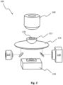
- FIGs. 1-5 illustrate various views of an SPR imaging system 100, according to an embodiment.
- the SPR imaging system 100 can comprise: (a) an optical assembly 110; (b) an SPR light source 120; (c) an SPR camera 130; (d) a bright field light source 140; and/or (e) a bright field camera 150.
- the SPR imaging system 100 can comprise a high optical resolution, such as an optical resolution not larger than 3 micrometers ( ⁇ m), 2 ⁇ m, etc.
- the SPR imaging system 100 also can comprise a wide SPR angle, such as an SPR angle ranging from 40 to 82 degrees.
- the SPR imaging system 100 can further comprise a large optical field of view, such as an optical field of view as great as 0.1 millimeters-squared (mm 2 ), 1 mm 2 , or 3 mm 2 .
- the SPR imaging system 100 is configured to simultaneously capture or process an SPR image and a bright field image in real time.
- the optical assembly 110 of the SPR imaging system 100 can comprise: (a) a hemispherical prism 112 that comprises a planar top surface 113 configured to support a surface-plasmon-resonance (SPR) sensor 170; (b) a high numerical aperture (NA) lens 114; and/or (c) a housing 116 configured to mount the hemispherical prism 112 and the high NA lens 114, such that the high NA lens 114 is located distal from the planar top surface 113 of the hemispherical prism 112.
- the top surface of the hemispherical prism is not planar or is not entirely planar.
- the hemispherical prism 112 configured to support the SPR sensor 170, no sensor supporting stage is needed, and the SPR imaging system 100 thus can have fewer heat leaking surfaces and fewer sources of mechanical vibration noise.
- the hemispherical prism 112 can comprise a high refractive index, such as a refractive index no less than 1.5.
- the high NA lens 114 can comprise a radius at least 1.5 times greater than a radius of the hemispherical prism 112. In some embodiments, the high NA lens 114 can comprise a high NA value, such as no less than 1.5.
- the hemispherical prism 112 and the high NA lens 114 can be configured to be firmly coupled to the housing 116 in order to eliminate any relative movement between the hemispherical prism 112 and the high NA lens 114 that can cause mechanical vibration noises.
- the housing 116 can enclose at least a portion of each of the hemispherical prism 112 and the high NA lens 114 for better temperature control.
- the housing 116 can enclose the area between the hemispherical prism 112 and the high NA lens 114.
- the housing 116 can leave the planar top surface 113 of the hemispherical prism 112 and the bottom surface of the high NA lens exposed, as in the exemplary embodiment shown in FIGs. 1 and 3 .
- the SPR light source 120 of the SPR imaging system 100 can be configured to emit a low-coherent monochromatic light beam 121 for SPR imaging toward the high NA lens 114.
- an incident angle of the low-coherent monochromatic light beam 121 from the SPR light source 120 towards the high NA lens 114 can be adjustable, such as by one or more additional optical components or by adjusting the location or angle of the SPR light source 120.
- the SPR camera 130 can be configured to capture an SPR image formed after the low-coherent monochromatic light beam 121 is incident upon and reflected by a metal-coated sample contacting surface 171 of the SPR sensor 170.
- the SPR imaging system 100 comprises the bright field light source 140 and the bright field camera 150 for bright field imaging.
- the bright field light source 140 can be configured to emit a bright field light beam 141 to illuminate the metal-coated sample contacting surface 171 of the SPR sensor 170
- the bright field camera 150 can be configured to capture a bright field image of the SPR sensor 170.
- the bright field light source 140 can additionally comprise a condenser.
- the condenser can be configured to render a light beam, that is emitted from the bright field light source 140 and originally divergent, into a parallel and/or convergent bright field light beam to illuminate the SPR sensor 170.
- the SPR imaging system 100 can be configured so that the bright field camera 150 can capture the bright field image of the SPR sensor 170 simultaneously with the SPR camera capturing the SPR image.
- the high NA lens 114 can be configured to refract the low-coherent monochromatic light beam 121 from the SPR light source 120 toward the hemispherical prism 112.
- the high NA lens 114 can condition the low-coherent monochromatic light beam 121.
- the conditioning provided by the high NA lens 114 can bend the refracting beam 30-60 degrees from incident beam path, for both beams towards and away from the sensor.
- the hemispherical prism 112 can be configured to collimate the low-coherent monochromatic light beam 121, as refracted by the high NA lens 114, toward the SPR sensor 170 that is coupled to the planar top surface 113 of the hemispherical prism 112.
- the SPR camera 130 and/or the bright field camera 150 can be communicably coupled to a computing device 180 ( FIG. 1 ), such as a computer or a server, that is configured to: receive and record the SPR image from the SPR camera; receive and record the bright field image from the bright field camera; calibrate the SPR image from the SPR camera; calibrate the bright field image from the bright field camera; and map the SPR image onto the bright field image for binding analysis.
- the computing device 180 FIG. 1
- 1 can be further configured to automatically perform one or more data processing procedures, including: (a) normalizing the SPR sensitivity of the sensor surface per pixel and removing the sensor inhomogeneity by one or more calibration techniques, such as an SPR profile scan, injection of a known index standard, a thermal response, or another known method to determine localized SPR sensor sensitivity; (b) removing sensor drift by leveling the baseline with reference, linear, and non-linear subtractions; (c) identifying anomalous data of binding behaviors and eliminating artifacts in the data by using Artificial Intelligence (“AI") to categorize binding behaviors and exclude the data which do not match between isotherm analysis and kinetic analysis; and/or (d) identifying one or more sets of data showing model behaviors as the model data and analyzing the model data to derive a measured result with a certain confidence level.
- AI Artificial Intelligence
- the SPR imaging system 100 can comprise additional optical components, such as one or more lenses, one or more mirrors, a phase-shift ring 161 ( FIG. 4 ), and/or a color filter 162 ( FIG. 5 ), and so forth, for adjusting the colors or directions of the light beams and/or the colors or contrast of the bright field image or the SPR image for SPR imaging, bright field imaging, phase-contrast imaging, and/or fluorescence imaging.
- additional optical components such as one or more lenses, one or more mirrors, a phase-shift ring 161 ( FIG. 4 ), and/or a color filter 162 ( FIG. 5 ), and so forth, for adjusting the colors or directions of the light beams and/or the colors or contrast of the bright field image or the SPR image for SPR imaging, bright field imaging, phase-contrast imaging, and/or fluorescence imaging.
- the phase-shift ring 161 can be configured for phase-contrast imaging with the bright field light source 140 and the bright field camera 150 to increase the contrast of the bright field image, and the phase-shift ring 161 can be located in any suitable place, such as between the hemispherical prism 112 and the high NA lens 116 or between the optical assembly 110 and the bright field camera 150.
- the bright field light source 140 and the bright field camera 150 can be further configured for fluorescence imaging with one of: (a) the bright field light beam 141 emitted by the bright field light source 140 comprising a colored light; or (b) the bright field light beam 141 emitted by the bright field light source 140 comprising a white light and the color filter 162 located at one of: between the bright field light source 140 and the SPR sensor 170 or in front of bright field camera 150, and configured to change one or more colors of bright field light beam 141.
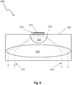
- FIG. 6 illustrates an optical assembly 200, according to an embodiment.
- the optical assembly 200 can comprise a hemispherical prism 212, a high NA lens 214, and/or a housing 216.
- the hemispherical prism 212 can comprise a planar top surface 213 configured to support an SPR sensor 270 with a metal-coated sample contacting surface 271.
- the top surface of the hemispherical prism is not planar or is not entirely planar.
- the housing 216 can be configured to mount the hemispherical prism 212 and the high NA lens 214, such that the high NA lens 214 is located distal from the planar top surface 213 of the hemispherical prism 212.
- an SPR imaging system adopting the optical assembly 200 can comprise: a high optical resolution, such as an optical resolution not larger than 3 ⁇ m, 1 ⁇ m, etc.; a wide SPR angle, such as an SPR angle ranging from 40 to 82 degrees; and/or a large optical field of view, such as an optical field of view as great as 0.1 mm 2 , 1 mm 2 , or 3 mm 2 .
- the optical assembly 200 is used for simultaneous SPR and bright field imaging.
- the hemispherical prism 212 can comprise a high refractive index, such as a refractive index no less than 1.5.
- the high NA lens 214 can comprise a radius at least 1.5 times greater than a radius of the hemispherical prism 212.
- the high NA lens 214 can comprise a high NA value, such as no less than 1.5.
- the hemispherical prism 212 and the high NA lens 214 can be configured to be firmly coupled to the housing 216 in order to eliminate any relative movement between the hemispherical prism 212 and the high NA lens 214 that can cause mechanical vibration noise.
- the housing 216 can enclose at least a portion of each of the hemispherical prism 212 and the high NA lens 114 for better temperature control, such as enclosing the area between the hemispherical prism 212 and the high NA lens 214.
- FIGs. 7-9 illustrate various views of an SPR imaging system 300, according to another embodiment.
- the SPR imaging system 300 can comprise: (a) an optical assembly 310; (b) an SPR light source 320; (c) an SPR camera 330; (d) a bright field light source 340; (e) a bright field camera 350; (f) a thermoelectric device 318; (g) a microfluidic device 372; and/or (h) a sensor translation mount 373 ( FIGs. 8-9 ).
- the optical assembly 310 can comprise a hemispherical prism 312, a high NA lens 314, a thermoelectric device 318, and/or a housing 316.
- the hemispherical prism 312, the high NA lens 314, and the housing 316 can be similar to the aforementioned hemispherical prism (112 ( FIGs. 1-5 ) or 212 ( FIG. 6 )), the high NA lens (114 ( FIGs. 1-5 ) or 214 ( FIG. 6 )), and/or the housing (116 ( FIGs. 1-5 ) or 216 ( FIG. 6 )), respectively.
- the thermoelectric device 318 can be configured to control the temperature of the SPR sensor 370, such as maintaining the temperature fluctuation of the SPR sensor 370 within 0.016 degrees Celsius (°C), in order to avoid noises such as baseline shift in the SPR response signal or change in SPR angle.
- the thermoelectric device 318 can be located within the optical assembly 310, such as near the top surface of the hemispherical prism 312, and/or partially or entirely surrounding the hemispherical prism 312, in order to maintain the temperature of the hemispherical prism 312 and, in turn, maintain the temperature of the SPR sensor 370.
- the microfluidic device 372 can be mountable on the SPR sensor 370 and configured to deliver a buffer solution with one or more ligand samples 363 onto the metal-coated sample contacting surface of the SPR sensor 370.
- the microfluidic device 372 also can comprise: a pump with buffer exchange and degas capability configured to control a flow of the buffer solution; and/or an auto-sampler configured to place one or more ligand samples onto the metal-coated sample contacting surface of the SPR sensor 370.
- the SPR imaging system 300 can comprise the sensor translation mount 373 to monitor more cell population on a single SPR sensor 370.
- the sensor translation mount 373 can be mountable on a planar top surface 313 of the hemispherical prism 312 and configured to hold the SPR sensor 370 and translate or move the SPR sensor 370, by an x adjust arm 3731 ( FIGs. 8-9 ) and a y adjust arm 3732 ( FIG.
- the top surface of the hemispherical prism 312 is not planar or is not entirely planar.
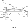
- FIGs. 10-11 show an SPR imaging system 400, according to an embodiment.
- the SPR imaging system 400 can comprise a motorized frame 423 configured to change an incident angle ⁇ of a low-coherent monochromatic light beam 421 relative to an optical assembly 410.
- a typical intensity-angle profile curve comprises a dip at the SPR angle, and an angle spread between the two steep slope regions near the dip is where a small angle shift can cause significant change in an intensity of SPR light shown in an SPR image; thus, measuring at the angle spread provides the highest sensitivity for SPR measurement.
- the SPR imaging system 400 can be configured to automatically scan and/or adjust the angle ⁇ of an incident low-coherent monochromatic light beam 421 to provide a wide range of angle adjustment, e.g., 40 - 82 degrees.
- the angle adjustment allows the detector to optimize the sensitivity in SPR measurement.
- the motorized frame 423 configured can be configured to move the SPR light source 420 vertically or in one linear direction only to adjust the light path and then the incident angle ⁇ of the low-coherent monochromatic light beam 421.
- the SPR imaging system 400 can further comprise a light intensity detector 425 ( FIG. 11 ) configured to monitor and record the intensity of the low-coherent monochromatic light beam 421 for intensity normalization and noise reduction.
- the SPR imaging system 400 also can comprise a beam splitter 424 ( FIG. 11 ), such as a 50% beam splitter, located in the light path of incident low-coherent monochromatic light beam 421 to split the incident low-coherent monochromatic light beam 421 into two portions.
- the SPR imaging system 400 can be configured to automatically detect and/or maintain the intensity of the low-coherent monochromatic light beam 421.
- a system can comprise an optical assembly, an SPR light source, and/or an SPR camera.
- the optical assembly in this and other embodiments can comprise a hemispherical prism that comprises a top surface configured to support a surface-plasmon-resonance (SPR) sensor; a high numerical aperture (NA) lens; and a housing configured to mount the hemispherical prism and the high NA lens such that the high NA lens is located distal from the top surface of the hemispherical prism.
- the SPR light source in this and other embodiments can be configured to emit a low-coherent monochromatic light beam for SPR imaging toward the high NA lens.
- the SPR camera in this and other embodiments can be configured to capture an SPR image formed after the low-coherent monochromatic light beam is incident upon and reflected by a metal-coated sample contacting surface of the SPR sensor.
- the high NA lens can be configured to refract the low-coherent monochromatic light beam from the SPR light source toward the hemispherical prism; and the hemispherical prism can be configured to collimate the low-coherent monochromatic light beam, as refracted by the high NA lens, toward the SPR sensor.
- a method for surface-plasmon-resonance (SPR) imaging can comprise: (a) coupling an SPR sensor to an optical assembly; (b) placing one or more ligand samples on a metal-coated sample contacting surface of the SPR sensor; (c) emitting a low-coherent monochromatic light beam from an SPR light source toward the high NA lens; and/or (d) capturing an SPR image by an SPR camera.
- SPR surface-plasmon-resonance
- the optical assembly can comprise a hemispherical prism comprising a top surface configured to support the SPR sensor; a high numerical aperture (NA) lens; and/or a housing configured to mount the hemispherical prism and the high NA lens such that the high NA lens is located distal from the top surface of the hemispherical prism.
- the high NA lens can be configured to refract the low-coherent monochromatic light beam from the SPR light source toward the hemispherical prism.
- the hemispherical prism in these and other embodiments can be configured to collimate the low-coherent monochromatic light beam, as refracted by the high NA lens, toward the SPR sensor.
- the SPR image can be formed after the low-coherent monochromatic light beam is incident upon and reflected by the metal-coated sample contacting surface of the SPR sensor.
- an optical assembly for surface plasmon resonance (SPR) imaging can comprise: (a) a hemispherical prism comprising a high refractive index no less than 1.5 and a planar top surface configured to support an SPR sensor; (b) a high numerical aperture (NA) lens comprising a radius at least 1.5 times greater than a radius of the hemispherical prism; (c) a housing configured to mount the hemispherical prism and the high NA lens such that the lens is located distal from the planar top surface of the hemispherical prism; (d) a high optical resolution, not larger than 3 ⁇ m; (e) a wide SPR angle, ranging from 40 to 82 degrees; and (f) a large optical field of view, not less than 0.1 mm 2 .
- SPR surface plasmon resonance
- the high NA lens can be configured to refract a light toward the hemispherical prism; and/or the hemispherical prism can be configured to collimate the light, as refracted by the high NA lens, toward the SPR sensor.
Landscapes
- Physics & Mathematics (AREA)
- General Physics & Mathematics (AREA)
- Chemical & Material Sciences (AREA)
- Analytical Chemistry (AREA)
- Optics & Photonics (AREA)
- Health & Medical Sciences (AREA)
- Life Sciences & Earth Sciences (AREA)
- Biochemistry (AREA)
- General Health & Medical Sciences (AREA)
- Immunology (AREA)
- Pathology (AREA)
- Investigating Or Analysing Materials By Optical Means (AREA)
Claims (15)
- Système (100) comprenant :
un ensemble optique (110) comprenant :un prisme hémisphérique (112) comprenant une surface supérieure (113) configurée pour supporter un capteur de résonance plasmonique de surface (SPR) (170) ; etune lentille à grande ouverture numérique (NA) (114) située de manière distale de la surface supérieure (113) du prisme hémisphérique (112) ;une source lumineuse SPR (120) configurée pour émettre un faisceau lumineux (121) pour l'imagerie SPR ; etune caméra SPR (130) configurée pour capturer une image SPR ; etune source lumineuse à champ clair (140) et une caméra à champ clair (150) pour l'imagerie à champ clair ;dans lequel :la lentille à grande NA (114) est configurée pour réfracter le faisceau lumineux (121) vers le prisme hémisphérique (112) ;le prisme hémisphérique (112) est configuré pour collimater le faisceau lumineux (121), tel que réfracté par la lentille à grande NA (114), vers le capteur SPR (170) ; etla lentille à grande NA (114) est en outre configurée pour recevoir et réfracter le faisceau lumineux (121) vers la caméra SPR (130), après que le faisceau lumineux (121) est réfléchi par une surface du capteur SPR (170) ;la source lumineuse à champ clair (140) est configurée pour émettre un faisceau lumineux à champ clair (141) pour éclairer la surface du capteur SPR (170) ; etla caméra à champ clair (150) est configurée pour capturer une image à champ clair du capteur SPR (170) simultanément avec la caméra SPR (130) capturant l'image SPR. - Système (100) selon la revendication 1, dans lequel l'ensemble optique (110) comprend en outre un dispositif thermoélectrique (318) configuré pour contrôler une température du capteur SPR (170) couplé au prisme hémisphérique (112).
- Système (100) selon la revendication 1, dans lequel un angle d'incidence du faisceau lumineux (121) provenant de la source lumineuse SPR (120) vers la lentille à grande NA (114) est réglable.
- Système (100) selon la revendication 1 comprenant en outre :
un détecteur d'intensité lumineuse (425) configuré pour surveiller et enregistrer une intensité du faisceau lumineux (121) pour la normalisation de l'intensité et la réduction du bruit. - Système (100) selon l'une quelconque des revendications 1 à 4 comprenant en outre un anneau de déphasage (161) situé entre le prisme hémisphérique (112) et la lentille à grande NA (114) et configuré pour une imagerie à contraste de phase avec la source lumineuse à champ clair (140) et la caméra à champ clair (150) .
- Système (100) selon l'une quelconque des revendications 1 à 5, dans lequel la source lumineuse à champ clair (140) et la caméra à champ clair (150) sont en outre configurées pour une imagerie par fluorescence avec l'un parmi :le faisceau lumineux à champ clair (141) émis par la source lumineuse à champ clair (140) comprenant une lumière colorée ; oule faisceau lumineux à champ clair (141) émis par la source lumineuse à champ clair (140) comprenant une lumière blanche et un filtre couleur (162) situé à l'un parmi : entre la source lumineuse à champ clair (140) et le capteur SPR (170) ou devant la caméra à champ clair (150), le filtre couleur (162) étant configuré pour changer une ou plusieurs couleurs du faisceau lumineux à champ clair (141).
- Système (100) selon l'une quelconque des revendications 1 à 6, dans lequel :la caméra SPR (130) et la caméra à champ clair (150) sont couplées de manière communicative à un système informatique (180) ; etle système informatique (180) est configuré pour :recevoir et enregistrer l'image SPR transmise depuis la caméra SPR (130) ;recevoir et enregistrer l'image à champ clair transmise depuis la caméra à champ clair (150) ;étalonner l'image SPR reçue depuis la caméra SPR (130) ;étalonner l'image à champ clair reçue depuis la caméra à champ clair (150) ; etmapper l'image SPR sur l'image à champ clair pour une analyse de liaison.
- Procédé d'imagerie par résonance plasmonique de surface (SPR) comprenant :
le couplage d'un capteur SPR (170) à un ensemble optique (110), l'ensemble optique (110) comprenant :un prisme hémisphérique (112) comprenant une surface supérieure configurée pour supporter le capteur SPR (170) ; etune lentille à grande ouverture numérique (NA) (114) ;le placement d'un ou plusieurs échantillons de ligand sur une surface du capteur SPR (170) ;l'émission d'un faisceau lumineux (121) à partir d'une source lumineuse SPR (120) ;la capture d'une image SPR par une caméra SPR (130) ;l'émission d'un faisceau lumineux à champ clair (141) à partir d'une source lumineuse à champ clair (140) pour éclairer la surface du capteur SPR (170) ; etla capture d'une image à champ clair du capteur SPR (170) par une caméra à champ clair (150) simultanément avec la capture de l'image SPR par la caméra SPR (130) ;dans lequel :la lentille à grande NA (114) est configurée pour réfracter le faisceau lumineux (121) à partir de la source lumineuse SPR (120) vers le prisme hémisphérique (112) ;le prisme hémisphérique (112) est configuré pour collimater le faisceau lumineux (121), tel que réfracté par la lentille à grande NA (114), vers le capteur SPR (170) ;l'image SPR est formée après que le faisceau lumineux (121) est incident sur et réfléchi par la surface du capteur SPR (170) ; etla lentille à grande NA (114) est en outre configurée pour recevoir et réfracter le faisceau lumineux (121) vers la caméra SPR (130), après que le faisceau lumineux (121) est réfléchi par la surface du capteur SPR (170). - Procédé selon la revendication 8, dans lequel l'ensemble optique (110) comprend en outre un dispositif thermoélectrique (318) configuré pour contrôler une température du capteur SPR (170) couplé au prisme hémisphérique (112).
- Procédé selon l'une quelconque des revendications 8 ou 9, comprenant en outre le réglage d'un angle incident du faisceau lumineux (121) depuis la source lumineuse SPR (120) vers la lentille à grande NA (114) pour permettre le balayage d'un profil d'angle SPR et pour optimiser une sensibilité de détection.
- Procédé selon l'une quelconque des revendications 8 à 10, dans lequel un ou plusieurs parmi :(a) l'ensemble optique (110) est configuré de sorte que le capteur SPR (170) comprenne en outre un ou plusieurs parmi :une résolution optique élevée, non supérieure à 3 µm ;un grand angle SPR, allant de 40 à 82 degrés ; ouun grand champ de vision optique, aussi grand que 3 mm2 ; ou(b) le procédé comprend en outre la fourniture d'un détecteur d'intensité lumineuse (425) pour la normalisation de l'intensité et la réduction du bruit, le détecteur d'intensité lumineuse (425) étant configuré pour surveiller et enregistrer une intensité du faisceau lumineux (121).
- Procédé selon l'une quelconque des revendications 8 à 11, comprenant en outre :
le placement d'un anneau de déphasage (161) entre le prisme hémisphérique (112) et la lentille à grande NA (114) et configuré pour une imagerie à contraste de phase avec la source lumineuse à champ clair (140) et la caméra à champ clair (150). - Procédé selon l'une quelconque des revendications 8 à 12, dans lequel la source lumineuse à champ clair (140) et la caméra à champ clair (150) sont en outre configurées pour une imagerie par fluorescence avec l'un parmi :le changement d'une couleur du faisceau lumineux à champ clair (141) émis par la source lumineuse à champ clair (140) ; oule placement d'un filtre de couleur (162) à l'un parmi : entre la source lumineuse à champ clair (140) et le capteur SPR (170) ou devant la caméra à champ clair (150), le filtre couleur (162) étant configuré pour changer une ou plusieurs couleurs du faisceau lumineux à champ clair (141).
- Procédé selon l'une quelconque des revendications 8 à 13, comprenant en outre :la transmission de l'image SPR de la caméra SPR (130) à un système informatique (180) ; etla transmission de l'image à champ clair de la caméra à champ clair (150) au système informatique (180), dans lequel :
le système informatique (180) est configuré pour :recevoir et enregistrer l'image SPR transmise depuis la caméra SPR (130) ;recevoir et enregistrer l'image à champ clair transmise par la caméra à champ clair (150) ;étalonner l'image SPR reçue depuis la caméra SPR (130) ;étalonner l'image à champ clair reçue depuis la caméra à champ clair (150) ; etmapper l'image SPR sur l'image à champ clair pour une analyse de liaison. - Système (100) selon l'une quelconque des revendications 1 à 7, dans lequel un ou plusieurs parmi :le prisme hémisphérique (112) comprend en outre un indice de réfraction élevé non inférieur à 1,5 ;la lentille à grande ouverture numérique (NA) (114) comprend un rayon au moins 1,5 fois supérieur à un rayon du prisme hémisphérique (112) ;le système (100) comprend en outre une résolution optique élevée, non supérieure à 3 µm ;le système (100) comprend en outre un grand angle SPR, allant de 40 à 82 degrés ;le système (100) comprend en outre un grand champ de vision optique, aussi grand que 3 mm2.
Applications Claiming Priority (2)
| Application Number | Priority Date | Filing Date | Title |
|---|---|---|---|
| US201862676983P | 2018-05-27 | 2018-05-27 | |
| PCT/US2019/034087 WO2019231869A1 (fr) | 2018-05-27 | 2019-05-27 | Système d'imagerie par résonance plasmonique de surface et procédé de mesure d'interactions moléculaires |
Publications (3)
| Publication Number | Publication Date |
|---|---|
| EP3803345A1 EP3803345A1 (fr) | 2021-04-14 |
| EP3803345A4 EP3803345A4 (fr) | 2022-06-08 |
| EP3803345B1 true EP3803345B1 (fr) | 2025-04-09 |
Family
ID=68698972
Family Applications (1)
| Application Number | Title | Priority Date | Filing Date |
|---|---|---|---|
| EP19812405.9A Active EP3803345B1 (fr) | 2018-05-27 | 2019-05-27 | Système d'imagerie par résonance plasmonique de surface et procédé de mesure d'interactions moléculaires |
Country Status (4)
| Country | Link |
|---|---|
| US (1) | US11327014B2 (fr) |
| EP (1) | EP3803345B1 (fr) |
| JP (1) | JP7357050B2 (fr) |
| WO (1) | WO2019231869A1 (fr) |
Families Citing this family (1)
| Publication number | Priority date | Publication date | Assignee | Title |
|---|---|---|---|---|
| WO2023079677A1 (fr) * | 2021-11-05 | 2023-05-11 | 日本電信電話株式会社 | Procédé et système d'évaluation de diffusion moléculaire |
Family Cites Families (53)
| Publication number | Priority date | Publication date | Assignee | Title |
|---|---|---|---|---|
| US4297032A (en) | 1980-02-14 | 1981-10-27 | The United States Of America As Represented By The Secretary Of The Navy | Dark field surface inspection illumination technique |
| CA1321488C (fr) * | 1987-08-22 | 1993-08-24 | Martin Francis Finlan | Detecteurs biologiques |
| US5351127A (en) * | 1992-06-17 | 1994-09-27 | Hewlett-Packard Company | Surface plasmon resonance measuring instruments |
| GB9623820D0 (en) | 1996-11-16 | 1997-01-08 | Secr Defence | Surface plasma resonance sensor |
| US6849397B2 (en) | 1999-05-04 | 2005-02-01 | Wisconsin Alumni Research Foundation | Label-free detection of nucleic acids via surface plasmon resonance |
| US6579726B1 (en) | 1999-07-30 | 2003-06-17 | Surromed, Inc. | Instruments, methods and reagents for surface plasmon resonance |
| JP2003514224A (ja) | 1999-11-12 | 2003-04-15 | サーロメッド・インコーポレーテッド | 表面プラズモン共鳴を使用するバイオセンシング |
| GB9928849D0 (en) | 1999-12-07 | 2000-02-02 | Secr Defence Brit | Surface plasmon resonance |
| JP3579321B2 (ja) | 2000-03-10 | 2004-10-20 | 財団法人神奈川科学技術アカデミー | 2次元イメージング表面プラズモン共鳴測定装置および測定方法 |
| US7670556B2 (en) | 2001-07-10 | 2010-03-02 | Wisconsin Alumni Research Foundation | Surface plasmon resonance imaging of micro-arrays |
| GB0119062D0 (en) * | 2001-08-06 | 2001-09-26 | Cambridge Consultants | Interferometer |
| AU2003286739A1 (en) | 2002-10-28 | 2004-05-25 | University Of Washington | Wavelength tunable surface plasmon resonance sensor |
| ES2661168T3 (es) | 2003-07-12 | 2018-03-27 | Accelerate Diagnostics, Inc. | Biodetección sensible y rápida |
| US20090213382A1 (en) | 2003-08-01 | 2009-08-27 | Ge Healthcare Bio-Sciences Ab | Optical resonance analysis unit |
| JP4593573B2 (ja) | 2004-01-08 | 2010-12-08 | オスモペン, リミテッド ライアビリティ カンパニー | 表面プラズモン共鳴型ナノリットル浸透圧計 |
| US7745143B2 (en) | 2004-11-19 | 2010-06-29 | Plexera, Llc | Plasmon resonance biosensor and method |
| JP2006208294A (ja) | 2005-01-31 | 2006-08-10 | Canon Inc | プラズモン共鳴および蛍光の同時イメージング装置及びイメージング方法 |
| US20070081163A1 (en) * | 2005-06-03 | 2007-04-12 | Minhua Liang | Method and apparatus for scanned beam microarray assay |
| WO2007004708A1 (fr) | 2005-06-30 | 2007-01-11 | National University Corporation NARA Institute of Science and Technology | Microscope |
| US20140185051A1 (en) | 2005-11-21 | 2014-07-03 | Plexera, Llc | Surface plasmon resonance spectrometer with an actuator driven angle scanning mechanism |
| US20090262356A1 (en) | 2008-03-27 | 2009-10-22 | Plexera, Llc | User interface and method for using an spr system |
| US7751052B2 (en) | 2006-12-04 | 2010-07-06 | Electronics And Telecommunications Research Institute | Surface plasmon resonance sensor capable of performing absolute calibration |
| US8289519B2 (en) | 2007-03-21 | 2012-10-16 | Stanford University | Surface plasmon resonance (SRP) microscopy systems, method of fabrication thereof, and methods of use thereof |
| JP2009036759A (ja) | 2007-07-10 | 2009-02-19 | Canon Inc | 検知装置及び観測対象の光学的特性の変化を検知する方法 |
| FR2924723B1 (fr) | 2007-12-11 | 2010-12-17 | Centre Nat Rech Scient | Support solide revetu d'au moins un film de metal et d'au moins une couche d'oxyde transparent et conducteur pour la detection par spr et/ou par une methode electrochimique |
| EP2232241B1 (fr) | 2007-12-20 | 2019-02-06 | JOHANSEN, Knut | Procede pour appareil de resonance plasmonique de surface |
| EP2237022B1 (fr) | 2008-01-16 | 2020-05-06 | Nippon Telegraph and Telephone Corporation | Dispositif et methode de mesure d'un debit |
| WO2009091039A1 (fr) | 2008-01-16 | 2009-07-23 | Nippon Telegraph And Telephone Corporation | Dispositif de mesure à résonance plasmonique de surface, cellule d'échantillon, et procédé de mesure |
| JP2009264744A (ja) * | 2008-04-21 | 2009-11-12 | Olympus Corp | 表面プラズモン共鳴測定装置 |
| JP2012501432A (ja) * | 2008-08-31 | 2012-01-19 | 富士レビオ株式会社 | 光学的キャビティモードの分析のための装置及び方法 |
| EP2335050A4 (fr) * | 2008-09-30 | 2014-01-15 | Univ Montreal | Instrument de résonance plasmonique de surface haute résolution utilisant un prisme de dove |
| KR101029473B1 (ko) | 2008-11-28 | 2011-04-18 | 한국표준과학연구원 | 초점타원계측 표면 플라즈몬 공명 측정장치 |
| KR101012056B1 (ko) | 2008-11-28 | 2011-02-01 | 한국표준과학연구원 | 다채널 타원계측 표면 플라즈몬 공명 측정장치 |
| CN102356315A (zh) | 2009-03-20 | 2012-02-15 | 安塔纳公司 | 含有在其表面固定的细胞的质量敏感性传感器及利用所述传感器检测配体结合的方法 |
| KR101043444B1 (ko) * | 2009-03-31 | 2011-06-22 | 케이맥(주) | 표면 플라즈몬 공명측정장치용 옵틱 인터페이스 |
| US9207117B2 (en) | 2010-07-28 | 2015-12-08 | University Of Delaware | Apparatus and method for performing surface plasmon resonance (SPR) spectroscopy with an infrared (IR) spectrometer |
| JP2012037268A (ja) * | 2010-08-04 | 2012-02-23 | Kobe Steel Ltd | 表面角度計測方法及び表面角度計測装置 |
| NL2005902C2 (en) * | 2010-11-25 | 2012-05-29 | Ibis Technologies B V | Method and apparatus for surface plasmon resonance angle scanning. |
| CN103620387B (zh) * | 2011-06-16 | 2017-02-15 | 3M创新有限公司 | 表面等离子体共振传感器元件和包括其的传感器 |
| FR2982027B1 (fr) | 2011-10-26 | 2014-01-03 | Thibaut Mercey | Puce microstructuree pour analyse par resonance des plasmons de surface, dispositif d'analyse comprenant ladite puce microstructuree et utilisation dudit dispositif |
| JP2016118389A (ja) * | 2013-02-28 | 2016-06-30 | 株式会社日立ハイテクノロジーズ | 相互作用解析装置 |
| CN203133094U (zh) | 2013-03-21 | 2013-08-14 | 浙江大学 | 一种全自动spr生物分析仪 |
| FR3004537A1 (fr) * | 2013-04-10 | 2014-10-17 | Centre Nat Rech Scient | Procede de mesure d'un milieu d'interet par resonance de plasmon de surface et systeme associe |
| US10408757B2 (en) | 2014-01-03 | 2019-09-10 | Arizona Board Of Regents On Behalf Of Arizona State University | Plasmonic imaging and detection of single DNA molecules |
| US20150168300A1 (en) | 2014-01-28 | 2015-06-18 | National Institute Of Standards And Technology | Article and process for modifying light |
| DE102015111426B3 (de) * | 2015-07-14 | 2016-10-20 | Fraunhofer-Gesellschaft zur Förderung der angewandten Forschung e.V. | Verfahren zur Phasenkontrastmikroskopie sowie Phasenkontrastmikroskop |
| US9745621B2 (en) * | 2015-08-17 | 2017-08-29 | Wisys Technology Foundation, Inc. | Temperature gradient surface plasmon resonance instrument |
| WO2017048871A1 (fr) | 2015-09-14 | 2017-03-23 | Essenlix Corp. | Dispositif et système pour analyser un échantillon, en particulier du sang et procédés pour les utiliser |
| EP3709001B1 (fr) | 2015-11-10 | 2024-03-06 | LacriSciences LLC | Systèmes et procédés de détermination de l'osmolarité d'échantillons |
| WO2017108733A1 (fr) | 2015-12-23 | 2017-06-29 | Koninklijke Philips N.V. | Détection optique de particules dans un fluide |
| US20170336612A1 (en) | 2016-05-19 | 2017-11-23 | Jonathan J. Foley, IV | Inhomogeneous Surface Wave Microscope |
| CN106918854B (zh) * | 2017-05-05 | 2019-05-24 | 北京航空航天大学 | 一种高数值孔径的油浸表面等离子体超透镜 |
| US10809194B2 (en) | 2018-05-27 | 2020-10-20 | Biosensing Instrument Inc. | Surface plasmon resonance imaging system and method for measuring molecular interactions |
-
2019
- 2019-05-27 JP JP2021517552A patent/JP7357050B2/ja active Active
- 2019-05-27 EP EP19812405.9A patent/EP3803345B1/fr active Active
- 2019-05-27 WO PCT/US2019/034087 patent/WO2019231869A1/fr not_active Ceased
-
2020
- 2020-10-19 US US17/074,274 patent/US11327014B2/en active Active
Also Published As
| Publication number | Publication date |
|---|---|
| JP7357050B2 (ja) | 2023-10-05 |
| US11327014B2 (en) | 2022-05-10 |
| US20210033534A1 (en) | 2021-02-04 |
| JP2021526225A (ja) | 2021-09-30 |
| WO2019231869A1 (fr) | 2019-12-05 |
| EP3803345A1 (fr) | 2021-04-14 |
| EP3803345A4 (fr) | 2022-06-08 |
Similar Documents
| Publication | Publication Date | Title |
|---|---|---|
| US9989749B2 (en) | Microscopy system with auto-focus adjustment by low-coherence interferometry | |
| CN100478733C (zh) | 光谱系统和用于确定所关心容积位置的方法 | |
| US20050236554A1 (en) | Optical interrogation system and method for 2-D sensor arrays | |
| WO2004079406A2 (fr) | Inspection de substrats transparents pour la detection de defauts | |
| KR20100033487A (ko) | 광학 특성 센서 | |
| US9671602B2 (en) | Measurement method for height profiles of surfaces using a differential interference contrast image | |
| WO2008142689A1 (fr) | Analyse par résonance optique à l'aide d'une source d'éclairage sous plusieurs angles | |
| JP5868327B2 (ja) | 光検出装置及び方法 | |
| EP3803345B1 (fr) | Système d'imagerie par résonance plasmonique de surface et procédé de mesure d'interactions moléculaires | |
| US7812955B2 (en) | Sample analysis apparatus and analysis method | |
| US10809194B2 (en) | Surface plasmon resonance imaging system and method for measuring molecular interactions | |
| US7315372B1 (en) | Instrument using near-field intensity correlation measurements for characterizing scattering of light by suspensions | |
| EP1715290A1 (fr) | Procédé et appareil de mesure confocale dans une machine à papier | |
| US20040109162A1 (en) | Measuring apparatus | |
| EP3662264A1 (fr) | Procédé et appareil pour l'analyse bactérienne | |
| JPH01145504A (ja) | 光学測定装置 | |
| CN117006969B (zh) | 光学测量系统 | |
| JP2002168780A (ja) | 屈折率変化測定装置 | |
| US20040046962A1 (en) | Apparatus for multiplexing two surface plasma resonance channels onto a single linear scanned array | |
| JP2003042926A (ja) | 生体分子吸着層の測定方法及び装置 | |
| JP2005265693A (ja) | 測定装置 | |
| US7868279B2 (en) | Focus detecting apparatus for focusing on surface of transparent substance | |
| CN112630194A (zh) | 一种基于扫描振镜的角度调制型spr传感器及spr检测设备 | |
| JP2003227792A (ja) | 全反射減衰を利用したセンサー | |
| US20020034731A1 (en) | Method and apparatus for measuring characteristics by analyzing a sample of human or animal body substances |
Legal Events
| Date | Code | Title | Description |
|---|---|---|---|
| STAA | Information on the status of an ep patent application or granted ep patent |
Free format text: STATUS: THE INTERNATIONAL PUBLICATION HAS BEEN MADE |
|
| PUAI | Public reference made under article 153(3) epc to a published international application that has entered the european phase |
Free format text: ORIGINAL CODE: 0009012 |
|
| STAA | Information on the status of an ep patent application or granted ep patent |
Free format text: STATUS: REQUEST FOR EXAMINATION WAS MADE |
|
| 17P | Request for examination filed |
Effective date: 20201224 |
|
| AK | Designated contracting states |
Kind code of ref document: A1 Designated state(s): AL AT BE BG CH CY CZ DE DK EE ES FI FR GB GR HR HU IE IS IT LI LT LU LV MC MK MT NL NO PL PT RO RS SE SI SK SM TR |
|
| AX | Request for extension of the european patent |
Extension state: BA ME |
|
| DAV | Request for validation of the european patent (deleted) | ||
| DAX | Request for extension of the european patent (deleted) | ||
| A4 | Supplementary search report drawn up and despatched |
Effective date: 20220509 |
|
| RIC1 | Information provided on ipc code assigned before grant |
Ipc: G02B 5/04 20060101ALI20220502BHEP Ipc: G01N 21/552 20140101AFI20220502BHEP |
|
| GRAP | Despatch of communication of intention to grant a patent |
Free format text: ORIGINAL CODE: EPIDOSNIGR1 |
|
| STAA | Information on the status of an ep patent application or granted ep patent |
Free format text: STATUS: GRANT OF PATENT IS INTENDED |
|
| INTG | Intention to grant announced |
Effective date: 20241104 |
|
| GRAS | Grant fee paid |
Free format text: ORIGINAL CODE: EPIDOSNIGR3 |
|
| GRAA | (expected) grant |
Free format text: ORIGINAL CODE: 0009210 |
|
| STAA | Information on the status of an ep patent application or granted ep patent |
Free format text: STATUS: THE PATENT HAS BEEN GRANTED |
|
| AK | Designated contracting states |
Kind code of ref document: B1 Designated state(s): AL AT BE BG CH CY CZ DE DK EE ES FI FR GB GR HR HU IE IS IT LI LT LU LV MC MK MT NL NO PL PT RO RS SE SI SK SM TR |
|
| REG | Reference to a national code |
Ref country code: GB Ref legal event code: FG4D |
|
| REG | Reference to a national code |
Ref country code: CH Ref legal event code: EP |
|
| REG | Reference to a national code |
Ref country code: DE Ref legal event code: R096 Ref document number: 602019068481 Country of ref document: DE |
|
| REG | Reference to a national code |
Ref country code: IE Ref legal event code: FG4D |
|
| PGFP | Annual fee paid to national office [announced via postgrant information from national office to epo] |
Ref country code: DE Payment date: 20250626 Year of fee payment: 7 |
|
| PGFP | Annual fee paid to national office [announced via postgrant information from national office to epo] |
Ref country code: FR Payment date: 20250606 Year of fee payment: 7 |
|
| PGFP | Annual fee paid to national office [announced via postgrant information from national office to epo] |
Ref country code: CH Payment date: 20250619 Year of fee payment: 7 |
|
| REG | Reference to a national code |
Ref country code: NL Ref legal event code: MP Effective date: 20250409 |
|
| PG25 | Lapsed in a contracting state [announced via postgrant information from national office to epo] |
Ref country code: NL Free format text: LAPSE BECAUSE OF FAILURE TO SUBMIT A TRANSLATION OF THE DESCRIPTION OR TO PAY THE FEE WITHIN THE PRESCRIBED TIME-LIMIT Effective date: 20250409 |
|
| REG | Reference to a national code |
Ref country code: AT Ref legal event code: MK05 Ref document number: 1783926 Country of ref document: AT Kind code of ref document: T Effective date: 20250409 |
|
| PG25 | Lapsed in a contracting state [announced via postgrant information from national office to epo] |
Ref country code: FI Free format text: LAPSE BECAUSE OF FAILURE TO SUBMIT A TRANSLATION OF THE DESCRIPTION OR TO PAY THE FEE WITHIN THE PRESCRIBED TIME-LIMIT Effective date: 20250409 Ref country code: ES Free format text: LAPSE BECAUSE OF FAILURE TO SUBMIT A TRANSLATION OF THE DESCRIPTION OR TO PAY THE FEE WITHIN THE PRESCRIBED TIME-LIMIT Effective date: 20250409 Ref country code: PT Free format text: LAPSE BECAUSE OF FAILURE TO SUBMIT A TRANSLATION OF THE DESCRIPTION OR TO PAY THE FEE WITHIN THE PRESCRIBED TIME-LIMIT Effective date: 20250811 |
|
| REG | Reference to a national code |
Ref country code: LT Ref legal event code: MG9D |
|
| PG25 | Lapsed in a contracting state [announced via postgrant information from national office to epo] |
Ref country code: NO Free format text: LAPSE BECAUSE OF FAILURE TO SUBMIT A TRANSLATION OF THE DESCRIPTION OR TO PAY THE FEE WITHIN THE PRESCRIBED TIME-LIMIT Effective date: 20250709 Ref country code: GR Free format text: LAPSE BECAUSE OF FAILURE TO SUBMIT A TRANSLATION OF THE DESCRIPTION OR TO PAY THE FEE WITHIN THE PRESCRIBED TIME-LIMIT Effective date: 20250710 |
|
| PG25 | Lapsed in a contracting state [announced via postgrant information from national office to epo] |
Ref country code: PL Free format text: LAPSE BECAUSE OF FAILURE TO SUBMIT A TRANSLATION OF THE DESCRIPTION OR TO PAY THE FEE WITHIN THE PRESCRIBED TIME-LIMIT Effective date: 20250409 |
|
| PG25 | Lapsed in a contracting state [announced via postgrant information from national office to epo] |
Ref country code: BG Free format text: LAPSE BECAUSE OF FAILURE TO SUBMIT A TRANSLATION OF THE DESCRIPTION OR TO PAY THE FEE WITHIN THE PRESCRIBED TIME-LIMIT Effective date: 20250409 |
|
| PG25 | Lapsed in a contracting state [announced via postgrant information from national office to epo] |
Ref country code: HR Free format text: LAPSE BECAUSE OF FAILURE TO SUBMIT A TRANSLATION OF THE DESCRIPTION OR TO PAY THE FEE WITHIN THE PRESCRIBED TIME-LIMIT Effective date: 20250409 |
|
| PG25 | Lapsed in a contracting state [announced via postgrant information from national office to epo] |
Ref country code: AT Free format text: LAPSE BECAUSE OF FAILURE TO SUBMIT A TRANSLATION OF THE DESCRIPTION OR TO PAY THE FEE WITHIN THE PRESCRIBED TIME-LIMIT Effective date: 20250409 |
|
| PG25 | Lapsed in a contracting state [announced via postgrant information from national office to epo] |
Ref country code: RS Free format text: LAPSE BECAUSE OF FAILURE TO SUBMIT A TRANSLATION OF THE DESCRIPTION OR TO PAY THE FEE WITHIN THE PRESCRIBED TIME-LIMIT Effective date: 20250709 |
|
| PG25 | Lapsed in a contracting state [announced via postgrant information from national office to epo] |
Ref country code: IS Free format text: LAPSE BECAUSE OF FAILURE TO SUBMIT A TRANSLATION OF THE DESCRIPTION OR TO PAY THE FEE WITHIN THE PRESCRIBED TIME-LIMIT Effective date: 20250809 |
|
| PG25 | Lapsed in a contracting state [announced via postgrant information from national office to epo] |
Ref country code: LV Free format text: LAPSE BECAUSE OF FAILURE TO SUBMIT A TRANSLATION OF THE DESCRIPTION OR TO PAY THE FEE WITHIN THE PRESCRIBED TIME-LIMIT Effective date: 20250409 |
|
| REG | Reference to a national code |
Ref country code: DE Ref legal event code: R097 Ref document number: 602019068481 Country of ref document: DE |
|
| PG25 | Lapsed in a contracting state [announced via postgrant information from national office to epo] |
Ref country code: SM Free format text: LAPSE BECAUSE OF FAILURE TO SUBMIT A TRANSLATION OF THE DESCRIPTION OR TO PAY THE FEE WITHIN THE PRESCRIBED TIME-LIMIT Effective date: 20250409 Ref country code: DK Free format text: LAPSE BECAUSE OF FAILURE TO SUBMIT A TRANSLATION OF THE DESCRIPTION OR TO PAY THE FEE WITHIN THE PRESCRIBED TIME-LIMIT Effective date: 20250409 |
|
| PG25 | Lapsed in a contracting state [announced via postgrant information from national office to epo] |
Ref country code: LU Free format text: LAPSE BECAUSE OF NON-PAYMENT OF DUE FEES Effective date: 20250527 |
|
| PG25 | Lapsed in a contracting state [announced via postgrant information from national office to epo] |
Ref country code: CZ Free format text: LAPSE BECAUSE OF FAILURE TO SUBMIT A TRANSLATION OF THE DESCRIPTION OR TO PAY THE FEE WITHIN THE PRESCRIBED TIME-LIMIT Effective date: 20250409 |
|
| PG25 | Lapsed in a contracting state [announced via postgrant information from national office to epo] |
Ref country code: EE Free format text: LAPSE BECAUSE OF FAILURE TO SUBMIT A TRANSLATION OF THE DESCRIPTION OR TO PAY THE FEE WITHIN THE PRESCRIBED TIME-LIMIT Effective date: 20250409 |
|
| PG25 | Lapsed in a contracting state [announced via postgrant information from national office to epo] |
Ref country code: SK Free format text: LAPSE BECAUSE OF FAILURE TO SUBMIT A TRANSLATION OF THE DESCRIPTION OR TO PAY THE FEE WITHIN THE PRESCRIBED TIME-LIMIT Effective date: 20250409 Ref country code: RO Free format text: LAPSE BECAUSE OF FAILURE TO SUBMIT A TRANSLATION OF THE DESCRIPTION OR TO PAY THE FEE WITHIN THE PRESCRIBED TIME-LIMIT Effective date: 20250409 |
|
| PG25 | Lapsed in a contracting state [announced via postgrant information from national office to epo] |
Ref country code: IT Free format text: LAPSE BECAUSE OF FAILURE TO SUBMIT A TRANSLATION OF THE DESCRIPTION OR TO PAY THE FEE WITHIN THE PRESCRIBED TIME-LIMIT Effective date: 20250409 |
|
| REG | Reference to a national code |
Ref country code: BE Ref legal event code: MM Effective date: 20250531 |
|
| PG25 | Lapsed in a contracting state [announced via postgrant information from national office to epo] |
Ref country code: MC Free format text: LAPSE BECAUSE OF FAILURE TO SUBMIT A TRANSLATION OF THE DESCRIPTION OR TO PAY THE FEE WITHIN THE PRESCRIBED TIME-LIMIT Effective date: 20250409 |
|
| PLBE | No opposition filed within time limit |
Free format text: ORIGINAL CODE: 0009261 |
|
| STAA | Information on the status of an ep patent application or granted ep patent |
Free format text: STATUS: NO OPPOSITION FILED WITHIN TIME LIMIT |
|
| REG | Reference to a national code |
Ref country code: CH Ref legal event code: L10 Free format text: ST27 STATUS EVENT CODE: U-0-0-L10-L00 (AS PROVIDED BY THE NATIONAL OFFICE) Effective date: 20260218 |
|
| 26N | No opposition filed |
Effective date: 20260112 |
|
| PGFP | Annual fee paid to national office [announced via postgrant information from national office to epo] |
Ref country code: GB Payment date: 20260303 Year of fee payment: 8 |
|
| PG25 | Lapsed in a contracting state [announced via postgrant information from national office to epo] |
Ref country code: IE Free format text: LAPSE BECAUSE OF NON-PAYMENT OF DUE FEES Effective date: 20250527 |
|
| PG25 | Lapsed in a contracting state [announced via postgrant information from national office to epo] |
Ref country code: BE Free format text: LAPSE BECAUSE OF NON-PAYMENT OF DUE FEES Effective date: 20250531 |