EP3804033B1 - Antenne à faisceau orientable présentant une polarisation variable pouvant être commandée - Google Patents
Antenne à faisceau orientable présentant une polarisation variable pouvant être commandée Download PDFInfo
- Publication number
- EP3804033B1 EP3804033B1 EP19814496.6A EP19814496A EP3804033B1 EP 3804033 B1 EP3804033 B1 EP 3804033B1 EP 19814496 A EP19814496 A EP 19814496A EP 3804033 B1 EP3804033 B1 EP 3804033B1
- Authority
- EP
- European Patent Office
- Prior art keywords
- scatterers
- polarization
- array
- antenna
- state
- Prior art date
- Legal status (The legal status is an assumption and is not a legal conclusion. Google has not performed a legal analysis and makes no representation as to the accuracy of the status listed.)
- Active
Links
Images



Classifications
-
- H—ELECTRICITY
- H01—ELECTRIC ELEMENTS
- H01Q—ANTENNAS, i.e. RADIO AERIALS
- H01Q3/00—Arrangements for changing or varying the orientation or the shape of the directional pattern of the waves radiated from an antenna or antenna system
- H01Q3/26—Arrangements for changing or varying the orientation or the shape of the directional pattern of the waves radiated from an antenna or antenna system varying the relative phase or relative amplitude of energisation between two or more active radiating elements; varying the distribution of energy across a radiating aperture
- H01Q3/30—Arrangements for changing or varying the orientation or the shape of the directional pattern of the waves radiated from an antenna or antenna system varying the relative phase or relative amplitude of energisation between two or more active radiating elements; varying the distribution of energy across a radiating aperture varying the relative phase between the radiating elements of an array
- H01Q3/34—Arrangements for changing or varying the orientation or the shape of the directional pattern of the waves radiated from an antenna or antenna system varying the relative phase or relative amplitude of energisation between two or more active radiating elements; varying the distribution of energy across a radiating aperture varying the relative phase between the radiating elements of an array by electrical means
- H01Q3/36—Arrangements for changing or varying the orientation or the shape of the directional pattern of the waves radiated from an antenna or antenna system varying the relative phase or relative amplitude of energisation between two or more active radiating elements; varying the distribution of energy across a radiating aperture varying the relative phase between the radiating elements of an array by electrical means with variable phase-shifters
-
- H—ELECTRICITY
- H01—ELECTRIC ELEMENTS
- H01Q—ANTENNAS, i.e. RADIO AERIALS
- H01Q3/00—Arrangements for changing or varying the orientation or the shape of the directional pattern of the waves radiated from an antenna or antenna system
- H01Q3/24—Arrangements for changing or varying the orientation or the shape of the directional pattern of the waves radiated from an antenna or antenna system varying the orientation by switching energy from one active radiating element to another, e.g. for beam switching
- H01Q3/247—Arrangements for changing or varying the orientation or the shape of the directional pattern of the waves radiated from an antenna or antenna system varying the orientation by switching energy from one active radiating element to another, e.g. for beam switching by switching different parts of a primary active element
-
- H—ELECTRICITY
- H01—ELECTRIC ELEMENTS
- H01Q—ANTENNAS, i.e. RADIO AERIALS
- H01Q21/00—Antenna arrays or systems
- H01Q21/0006—Particular feeding systems
-
- H—ELECTRICITY
- H01—ELECTRIC ELEMENTS
- H01Q—ANTENNAS, i.e. RADIO AERIALS
- H01Q21/00—Antenna arrays or systems
- H01Q21/24—Combinations of antenna units polarised in different directions for transmitting or receiving circularly and elliptically polarised waves or waves linearly polarised in any direction
- H01Q21/245—Combinations of antenna units polarised in different directions for transmitting or receiving circularly and elliptically polarised waves or waves linearly polarised in any direction provided with means for varying the polarisation
-
- H—ELECTRICITY
- H01—ELECTRIC ELEMENTS
- H01Q—ANTENNAS, i.e. RADIO AERIALS
- H01Q3/00—Arrangements for changing or varying the orientation or the shape of the directional pattern of the waves radiated from an antenna or antenna system
- H01Q3/01—Arrangements for changing or varying the orientation or the shape of the directional pattern of the waves radiated from an antenna or antenna system varying the shape of the antenna or antenna system
-
- H—ELECTRICITY
- H01—ELECTRIC ELEMENTS
- H01Q—ANTENNAS, i.e. RADIO AERIALS
- H01Q3/00—Arrangements for changing or varying the orientation or the shape of the directional pattern of the waves radiated from an antenna or antenna system
- H01Q3/26—Arrangements for changing or varying the orientation or the shape of the directional pattern of the waves radiated from an antenna or antenna system varying the relative phase or relative amplitude of energisation between two or more active radiating elements; varying the distribution of energy across a radiating aperture
- H01Q3/2605—Array of radiating elements provided with a feedback control over the element weights, e.g. adaptive arrays
- H01Q3/2611—Means for null steering; Adaptive interference nulling
- H01Q3/2629—Combination of a main antenna unit with an auxiliary antenna unit
- H01Q3/2635—Combination of a main antenna unit with an auxiliary antenna unit the auxiliary unit being composed of a plurality of antennas
-
- H—ELECTRICITY
- H04—ELECTRIC COMMUNICATION TECHNIQUE
- H04B—TRANSMISSION
- H04B7/00—Radio transmission systems, i.e. using radiation field
- H04B7/02—Diversity systems; Multi-antenna system, i.e. transmission or reception using multiple antennas
- H04B7/04—Diversity systems; Multi-antenna system, i.e. transmission or reception using multiple antennas using two or more spaced independent antennas
- H04B7/06—Diversity systems; Multi-antenna system, i.e. transmission or reception using multiple antennas using two or more spaced independent antennas at the transmitting station
- H04B7/0613—Diversity systems; Multi-antenna system, i.e. transmission or reception using multiple antennas using two or more spaced independent antennas at the transmitting station using simultaneous transmission
- H04B7/0615—Diversity systems; Multi-antenna system, i.e. transmission or reception using multiple antennas using two or more spaced independent antennas at the transmitting station using simultaneous transmission of weighted versions of same signal
- H04B7/0617—Diversity systems; Multi-antenna system, i.e. transmission or reception using multiple antennas using two or more spaced independent antennas at the transmitting station using simultaneous transmission of weighted versions of same signal for beam forming
-
- H—ELECTRICITY
- H04—ELECTRIC COMMUNICATION TECHNIQUE
- H04B—TRANSMISSION
- H04B7/00—Radio transmission systems, i.e. using radiation field
- H04B7/02—Diversity systems; Multi-antenna system, i.e. transmission or reception using multiple antennas
- H04B7/10—Polarisation diversity; Directional diversity
-
- H—ELECTRICITY
- H01—ELECTRIC ELEMENTS
- H01Q—ANTENNAS, i.e. RADIO AERIALS
- H01Q13/00—Waveguide horns or mouths; Slot antennas; Leaky-waveguide antennas; Equivalent structures causing radiation along the transmission path of a guided wave
- H01Q13/20—Non-resonant leaky-waveguide or transmission-line antennas; Equivalent structures causing radiation along the transmission path of a guided wave
- H01Q13/28—Non-resonant leaky-waveguide or transmission-line antennas; Equivalent structures causing radiation along the transmission path of a guided wave comprising elements constituting electric discontinuities and spaced in direction of wave propagation, e.g. dielectric elements or conductive elements forming artificial dielectric
-
- H—ELECTRICITY
- H01—ELECTRIC ELEMENTS
- H01Q—ANTENNAS, i.e. RADIO AERIALS
- H01Q15/00—Devices for reflection, refraction, diffraction or polarisation of waves radiated from an antenna, e.g. quasi-optical devices
- H01Q15/24—Polarising devices; Polarisation filters
-
- H—ELECTRICITY
- H01—ELECTRIC ELEMENTS
- H01Q—ANTENNAS, i.e. RADIO AERIALS
- H01Q15/00—Devices for reflection, refraction, diffraction or polarisation of waves radiated from an antenna, e.g. quasi-optical devices
- H01Q15/24—Polarising devices; Polarisation filters
- H01Q15/242—Polarisation converters
- H01Q15/244—Polarisation converters converting a linear polarised wave into a circular polarised wave
-
- H—ELECTRICITY
- H01—ELECTRIC ELEMENTS
- H01Q—ANTENNAS, i.e. RADIO AERIALS
- H01Q21/00—Antenna arrays or systems
- H01Q21/24—Combinations of antenna units polarised in different directions for transmitting or receiving circularly and elliptically polarised waves or waves linearly polarised in any direction
-
- H—ELECTRICITY
- H01—ELECTRIC ELEMENTS
- H01Q—ANTENNAS, i.e. RADIO AERIALS
- H01Q25/00—Antennas or antenna systems providing at least two radiating patterns
-
- H—ELECTRICITY
- H01—ELECTRIC ELEMENTS
- H01Q—ANTENNAS, i.e. RADIO AERIALS
- H01Q3/00—Arrangements for changing or varying the orientation or the shape of the directional pattern of the waves radiated from an antenna or antenna system
- H01Q3/24—Arrangements for changing or varying the orientation or the shape of the directional pattern of the waves radiated from an antenna or antenna system varying the orientation by switching energy from one active radiating element to another, e.g. for beam switching
Definitions
- the present disclosure relates to directional or steerable beam antennas, of the type employed in such applications as radar and communications. More specifically, it relates to leaky-waveguide antennas, of the type including a dielectric feed line (i.e., a potentially leaky waveguide) loaded with scatterers (antenna elements), where coupling between the scatterers and the feed line can be altered by switches, whereby the antenna's beam shape and direction are determined by the pattern of the switches that are respectively turned on and off.
- Steerable beam antennas are capable of sending electromagnetic signals in, and receiving electromagnetic signals from, desired directions.
- Such antennas are used, for example, in various types of radar, such as surveillance radar and collision avoidance radar.
- the receiving or transmitting beam is generated by a set of scatterers coupled to the feed line or waveguide. Interacting with the feed line, the scatterers create leaky waves propagating outside of the feed line. If the scatterers are properly phased, they create a coherent beam propagating in a specific direction.
- the leakage strength and phase caused by each scatterer depend on the geometry and location of the scatterer relative to the feed line or waveguide. The coupling strength can be controlled by changing the geometry of the scattering elements.
- the shape and direction of the scattered beam can be controlled by varying the scatterer geometry or topology.
- the geometry (topology) of the scatterers can be electronically altered by using microwave (or other suitable) switches connecting parts of the scatterers.
- microwave (or other suitable) switches connecting parts of the scatterers.
- the shape and direction of the antenna beam can be controlled electronically by changing the state of the switches. Different ON/OFF switch patterns result in different beam shapes and/or directions.
- switches integrated into the structure of the antenna elements or scatterers may be used for this purpose, such as semiconductor switches (e.g., PIN diodes, bipolar and MOSFET transistors, varactors, photo-diodes and photo-transistors, semiconductor-plasma switches, phase-change switches), MEMS switches, piezoelectric switches, ferro-electric switches, gas-plasma switches, electromagnetic relays, thermal switches, etc.
- semiconductor switches e.g., PIN diodes, bipolar and MOSFET transistors, varactors, photo-diodes and photo-transistors, semiconductor-plasma switches, phase-change switches
- MEMS switches piezoelectric switches
- ferro-electric switches ferro-electric switches
- gas-plasma switches electromagnetic relays
- thermal switches etc.
- semiconductor plasma switches have been used in antennas described in US Patent 7,151,499 .
- a specific example of an antenna in which the geometry of the scattering elements is controllably varied by semiconductor plasma switches is disclosed and claimed in US Patent 7,777,286
- US Patent 9,698,478 discloses an electronically-controlled steerable beam antenna system, of the general type described above, comprising a feed line or transmission line defining an axis x; and first and second arrays of electronically-controlled switchable scatters distributed along the axis x, each of the scatterers in the first and second arrays being switchable between a "high" scattering state and a "low” scattering state to scatter an electromagnetic wave propagating through the feed line so as to form a steerable antenna beam.
- the high state/low state scatterer pattern of the first array is advantageously quasi-periodic.
- the output beam position is controlled by varying the period.
- the scatterers of the first array are configured to scatter an electromagnetic wave propagating through the feed line.
- the high-state scatterers in the second array follow the similar quasi-periodic pattern, with the same period P, but the pattern of the second array can be shifted along the x axis relative to the pattern of the first array.
- Prior art document US 2015 357 711 relates to suppression of parasitic radiation in steerable beam antennas.
- Prior art document US 2016 372 834 discloses a surface scattering antenna comprising two separate beams, each propagating in a separate direction, and having different polarizations.
- this disclosure relates to a steerable beam antenna, wherein the antenna is controllably operable to produce a steerable beam in any of several selectable polarizations.
- a steerable beam antenna system comprises a feed line or transmission line defining an axis X; and first and second arrays of electronically-controllable switchable scatters distributed on opposite sides of the feed line parallel to the axis X, each of the scatterers in the first and second arrays being switchable between a "high" scattering state and a "low” scattering state to scatter an electromagnetic wave propagating through the feed line so as to form a steerable antenna beam.
- the high state/low state scatterer patterns of the first and second arrays are advantageously quasi-periodic, and the output beam direction is controlled by varying the scatterer period, as in the antenna disclosed in the above-mentioned '478 patent.
- the scatterers of the first array configured to provide an antenna output having a first polarization
- the scatterers of the second array are configured so that the portion of the antenna output scattered by the second array has a second polarization orthogonal to the first polarization of the portion scattered by the first array.
- the high state/low state scatterer patterns of both the first and second arrays have the same period (which, for the purpose of this disclosure, is denoted "P")
- the pattern of the second array may be shifted along the axis X defined by the feed line by a period shift ⁇ P.
- the resulting polarization of the antenna beam depends on the value of ⁇ P.
- ⁇ P non-zero period shift
- the scatterers in the first and second arrays are switched, preferably under electronic control, between the high state and the low state.
- the value of ⁇ P can be selectively varied in a prescribed sequence, for example, by selectively switching the appropriate scatterers in the second array between their high states and low states by electronic switches that can be actuated, for example, under the control of a suitably programmed processor. This arrangement would yield polarizations that would be varied in accordance with the prescribed sequence.
- the scatterers in the second array can be operated in their respective high states and low states in a specific period shift yielding a first polarization, until their high states and low states are switched to a different period shift yielding a second polarization.
- a polarization state can be selected to optimize performance of the antenna beam in a particular situation or application. If the inter-scatterer spacing d is small enough, this approach allows the generation of radiated beams with the desired mix of linear and circular polarizations (including various elliptical polarizations).
- the above-described polarization results can be achieved with the scatterers of both the first and second arrays being shaped as either monopoles or dipoles.
- the scatterers of the first array are parallel to each other, each forming an angle ⁇ with the feed line axis, while the scatterers of the second array are parallel to each other, each forming an angle - ⁇ with the feed line axis.
- the angle ⁇ is selected so that each scatterer radiates with a linear polarization of 45° relative to the feed line axis.
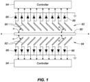
- Figure 1 diagrammatically illustrates a steerable beam antenna with an arrangement of scatterers or pixels in accordance with aspects of this disclosure that provides multiple controllable polarizations for a steerable radiated beam.
- the scatterers may be monopoles or dipoles, but, for simplicity of this discussion, they shall be assumed to be monopoles.
- an electromagnetic signal feed line 80 defines an X axis, with a first linear array 82 of scatterers or pixels 90 and a complementary linear second array 84 of scatterers or pixels 92 arranged on opposite sides of the feed line 80 parallel to the X axis.
- Each of the scatterers 90 in the first array 82 and each of the scatterers 92 in the second array 84 is switchable (preferably by electronic control) between a high state (H-state, represented by a "1" in the drawings) and a low state (L-state, represented by a “0” in the drawings) to scatter a wave propagating through the feed line 80 so as to form a steerable antenna beam, in which the beam direction is controlled via the period of the reciprocating patterns of the H-state scatterers and the L-state in the first and second arrays, respectively.
- H-state high state
- L-state low state
- each of the scatterers 90 in the first array 82 and each of the scatterers 92 in the second array 84 may be implemented as a short linear segment of a microstrip line, formed as, for example, as a conductive trace on a suitable substrate by known circuit fabrication methods.
- the scatterers 90 of the first array 82 are parallel to each other, with each scatterer 90 forming an angle ⁇ relative to the X axis defined by the feed line 80.
- the scatterers 92 of the second array 84 are likewise parallel to each other, with each scatterer 92 forming an angle - ⁇ relative to the X axis, whereby the first and second arrays are mirror images of each other, with the feed line 80 as a mirror plane.
- the magnitude of the angle ⁇ is selected so that the output radiation is linearly polarized at 45° relative to the feed line 80, with the scatterers of the first array providing a first scattered beam portion having a first polarization, and the scatterers in the second array providing a second scattered beam portion having a second polarization orthogonal to the first polarization.
- the value of ⁇ is nominally 45°, but it will depend on, for example, the dielectric constant and geometry of the feed line.
- RF interference between the scatterers and the feed line, ground, and other antenna elements may require the dipole/monopole orientations (angle ⁇ ) to deviate from 45° relative to the feed line axis to obtain orthogonal polarizations between the first and second arrays of scatterers.
- the scatterers in each array are equidistantly spaced from each other by a separation distance d that is as small as possible: no greater than one-third the wavelength ⁇ of the radiated beam, and preferably less than ⁇ /4, such as, for example, ⁇ /8 or ⁇ /16, or even less.
- Each of the scatterers in the first array 82 and the second array 84 is controllably connectable to ground by a switch 86 that may be implemented, for example, by a PIN diode. Although shown schematically as diodes, the switches 86 can be implemented as controllable resistors, MEMs, MOSFETSs, or any other suitable switching component. The switches 86 can be implemented as separate lumped elements, or integrated into the substrate, as when the antenna is formed on a semiconductor (e.g., silicon) wafer. They can be controlled electronically, photo-electrically, thermo-electrically, magneto-electrically, or electro-mechanically, depending on the needs of any particular application. As shown, a switch 86 is associated with each of the scatterers in both the first array 82 and the second array 84.
- Switching a switch 86 to ground transitions its associated scatterer from the L -state (0) to the H -state (1), while opening the switch (disconnecting its associated scatterer from ground) transitions its associated scatterer from the H -state (1) to the L -state (0).
- the switches 86 in each array may advantageously be operated in response to a control signal from a controller 94 that, in some embodiments, operates the switches 86 in accordance with a software program that is retrieved from memory (not shown) or is otherwise input to the controller 94.
- the controller 94 itself, in many embodiments, will be implemented as a programmable processor, whereby the processor is configured by instructions in the program to perform the switch operations needed to implement the selectable radiation polarizations in accordance with this disclosure, as explained below.
- the pattern of H -state scatterers and L -state scatterers in the first array 82 will have a first correlation to the pattern in the second array 84 that produces a radiated beam having a first type of polarization.
- the pattern of at least one of the arrays is shifted relative to the pattern of the other array, by appropriate actuation of the switches 86, by a period shift ⁇ P that results in a second correlation that produces a beam having a selectable second type of polarization.
- Figures 2A, 2B , 2C, and 2D illustrate how the polarization of the output beam can be controllably varied by shifting the pattern of H -state and L -state scatterers 90 in the first array 82 relative to the corresponding pattern of the scatterers 92 in the second array 84, or vice versa.
- the shifting is done by actuating the switches 86 of the appropriate scatterers in the either the first array 82 or the second array 84 to achieve the pattern shifts corresponding to the desired polarization.
- the period P of each array is nd, where n is the number of scatterers between successive H -state scatters (4 in the illustrated example) and d is the separation distance between each adjacent pair of scatterers. While n can be any integer greater than 1, in the illustrated example, each period consists of three successive L -state scatterers or pixels and one H -state scatterer or pixel. Thus, a quarter period (nd/4) will encompass one scatterer or pixel.
- the beam polarization provided by both arrays is linear, with the polarization components produced by both arrays in a direction orthogonal to axis X canceling each other.
- the resultant output beam has a linear polarization in a direction parallel to the X -axis (which may be referred to as "horizontal” or "H" polarization).
- the resultant output beam is linearly polarized in the direction orthogonal to the X-axis (which may be referred to as "vertical” or "V" polarization).
- the resultant output beam is circularly polarized in the clockwise or left-hand direction ("CL" polarization).
- any one of the relationships between the respective patterns of the first and second arrays illustrated in Figs. 2A-2D may be considered the initial relationship or correlation that produces a first type of polarization, and any one of the other relationships may be considered the period-shifted relationship or correlation that produces a second type of polarization.
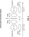
- Figure 3 is a graphical representation showing the types of polarizations obtained with different values of ⁇ P.
- ⁇ P is not zero, d, or an integral multiple of d
- the period shifts ( ⁇ P) will result in polarizations that will deviate from the desired linear or circular polarization.
- ⁇ P the period shifts
- Figure 4 is a graphical representation of the relative polarization components in antenna beams formed with different period shifts ( ⁇ P) described above and illustrated in Figs. 2A-2D .
- controllable polarization feature disclosed herein can be adapted to a wide variety of steerable beam antenna systems, and that antenna systems employing this feature can be operated to provide controlled polarizations in different sequences as will be suitable to different applications and circumstances.
Landscapes
- Engineering & Computer Science (AREA)
- Computer Networks & Wireless Communication (AREA)
- Signal Processing (AREA)
- Variable-Direction Aerials And Aerial Arrays (AREA)
Claims (12)
- Système d'antenne à faisceau orientable utilisable pour produire un faisceau d'antenne orientable ayant une pluralité de polarisations sélectionnables, le système d'antenne comprenant :une ligne d'alimentation (80) définissant un axe X ;un premier réseau (82) de diffuseurs commutables (90) disposé le long d'un premier côté de la ligne d'alimentation (80) parallèle à l'axe X ; etun second réseau (84) de diffuseurs commutables (92) disposé le long d'un second côté opposé de la ligne d'alimentation (80) parallèle à l'axe X, dans lequel le second réseau (84) de diffuseurs commutables (92) est une image miroir du premier réseau (82) de diffuseurs commutables (90) par rapport à un plan miroir défini par la ligne d'alimentation (80) ;dans lequel le premier réseau (82) de diffuseurs (90) est configuré pour diffuser une onde électromagnétique se propageant à travers la ligne d'alimentation (80) de manière à former une première partie de faisceau d'antenne orientable avec une première polarisation, et le second réseau (84) de diffuseurs (92) est configuré pour diffuser l'onde électromagnétique se propageant à travers la ligne d'alimentation (80) de manière à former une seconde partie de faisceau d'antenne orientable avec une seconde polarisation orthogonale à la première polarisation ;dans lequel chacun des diffuseurs (90 et 92) des premier et second réseaux (82 et 84) peut être commuté entre un état haut et un état bas, dans lequel les diffuseurs (90 et 92) à l'état haut et les diffuseurs (90 et 92) à l'état bas dans chacun des premier et second réseaux (82 et 84) définit un motif ayant une période P = nd, où n est le nombre de diffuseurs (90 et 92) entre diffuseurs successifs (90 et 92) à l'état haut et d est la distance de séparation entre des diffuseurs adjacents (90 et 92) qui n'est pas supérieure au tiers de la longueur d'onde λ de l'onde électromagnétique qui se propage ; etdans lequel les diffuseurs (90 et 92) du premier et second réseaux (82 et 84) sont commutables pour décaler le motif de diffuseurs (90 et 92) à l'état haut et de diffuseurs (90 et 92) à l'état bas dans au moins l'un des premier et second réseaux (82 et 84) par rapport au motif de diffuseurs (90 et 92) à l'état haut et de diffuseurs (90 et 92) à l'état bas dans l'autre des premier et second réseaux (82 et 84) par un décalage de période sélectionnable ΔP qui produit un faisceau d'antenne orientable ayant une polarisation sélectionnée parmi la pluralité de polarisations sélectionnables.
- Système d'antenne à faisceau orientable selon la revendication 1, dans lequel les diffuseurs (90 et 92) du premier et second réseaux (82 et 84) sont commutables en réponse à un signal de commande électronique.
- Système d'antenne à faisceau orientable selon la revendication 1, dans lequel le décalage de période sélectionnable ΔP est un multiple de la distance de séparation d.
- Antenne à faisceau orientable selon la revendication 3, dans laquelle, lorsque le décalage de période sélectionnable ΔP est un multiple entier de la distance de séparation d, une polarisation de faisceau d'antenne orientable est obtenue qui est l'une d'une polarisation verticale, d'une polarisation horizontale, d'une polarisation circulaire à gauche et d'une polarisation circulaire à droite.
- Antenne à faisceau orientable selon la revendication 1, dans laquelle chaque diffuseur (90 et 92) du premier et second réseaux (82 et 84) est fonctionnellement associé à un élément de commutation pouvant être connecté à la terre, et dans laquelle chaque diffuseur (90 et 92) du premier et second réseaux (82 et 84) est commuté (a) de l'état bas à l'état haut lorsque son élément de commutation associé (90 et 92) connecte le diffuseur à la terre, et (b) de l'état haut à l'état bas lorsque son élément de commutation associé déconnecte le diffuseur (90 et 92) de la terre.
- Antenne à faisceau orientable selon la revendication 1, dans laquelle tous les diffuseurs (90) du premier réseau (82) forment un angle α par rapport à l'axe X, et dans laquelle tous les diffuseurs (92) du second réseau (84) forment un angle -α par rapport à l'axe X.
- Antenne à faisceau orientable selon la revendication 1, dans laquelle la distance de séparation d est inférieure à λ/4.
- Procédé de variation commandée de la polarisation d'un faisceau électromagnétique de longueur d'onde λ rayonné provenant d'une antenne à faisceau orientable ayant une ligne d'alimentation de signal électromagnétique définissant un axe X, le procédé comprenant :(a) la fourniture d'un premier réseau linéaire (82) de diffuseurs (90) sur un premier côté de la ligne d'alimentation de signal parallèle à l'axe X, dans lequel chacun des diffuseurs (90) du premier réseau (82) définit un angle α par rapport à l'axe X, et dans lequel les diffuseurs (90) du premier réseau (82) sont séparés par une distance d qui n'est pas supérieure à un tiers λ, moyennant quoi les diffuseurs (90) du premier réseau (82) fournissent une première partie de faisceau diffusé ayant une première polarisation ;(b) la fourniture d'un second réseau linéaire (84) de diffuseurs (82) sur un second côté de la ligne d'alimentation de signal opposé au premier côté, le second réseau (84) étant parallèle à l'axe X, dans lequel chacun des diffuseurs (92) du second réseau (84) définit un angle -α par rapport à l'axe X, et dans lequel les diffuseurs (92) du second réseau (84) sont séparés par la distance d, moyennant quoi les diffuseurs (92) du second réseau (84) fournissent une seconde partie de faisceau diffusé ayant une seconde polarisation orthogonale à la première polarisation ;(c) l'établissement d'un premier motif de diffuseurs (90) dans un état haut et de diffuseurs (90) dans un état bas dans le premier réseau (82), et un second motif de diffuseurs (92) à l'état haut et de diffuseurs (92) à l'état bas dans le second réseau (84), dans lequel chaque diffuseur (90 et 92) du premier et second réseaux (82 et 84) est configuré à l'état haut en étant connecté à la terre, et à l'état bas en étant déconnecté de la terre, dans lequel chacun des premier et second motifs est défini par une période P = nd entre des diffuseurs successifs (90 et 92) à l'état haut, où n est un nombre entier positif supérieur à 1, et dans lequel le premier motif et le second motif sont corrélés de manière à produire un faisceau orientable diffusé provenant de l'antenne ayant un premier type de polarisation ; et(d) la commutation sélective des diffuseurs (90 et 92) de l'un des premier et second réseaux (82 et 84) de l'état haut à l'état bas, et de l'état bas à l'état haut, de manière à décaler l'un des premier et second motifs par rapport à l'autre des premier et second motifs par un décalage de période qui produit un faisceau orientable diffusé provenant de l'antenne ayant un second type de polarisation différent du premier type de polarisation.
- Procédé selon la revendication 8, dans lequel l'étape de commutation sélective est réalisée en réponse à un signal électronique.
- Procédé selon la revendication 9, dans lequel le signal électronique est reçu d'un dispositif de commande (94).
- Procédé selon la revendication 8, dans lequel le premier type de polarisation est choisi dans le groupe de types de polarisation constitué d'une polarisation horizontale, d'une polarisation verticale, d'une polarisation circulaire à gauche et d'une polarisation circulaire à droite, et dans lequel le second type de polarisation est un type de polarisation différent du premier type de polarisation sélectionné dans le groupe de types de polarisation.
- Procédé selon la revendication 8, dans lequel la distance d est inférieure à À/4.
Applications Claiming Priority (2)
| Application Number | Priority Date | Filing Date | Title |
|---|---|---|---|
| US16/003,639 US11121465B2 (en) | 2018-06-08 | 2018-06-08 | Steerable beam antenna with controllably variable polarization |
| PCT/US2019/034732 WO2019236383A1 (fr) | 2018-06-08 | 2019-05-30 | Antenne à faisceau orientable présentant une polarisation variable pouvant être commandée |
Publications (4)
| Publication Number | Publication Date |
|---|---|
| EP3804033A1 EP3804033A1 (fr) | 2021-04-14 |
| EP3804033A4 EP3804033A4 (fr) | 2022-03-16 |
| EP3804033B1 true EP3804033B1 (fr) | 2024-10-09 |
| EP3804033C0 EP3804033C0 (fr) | 2024-10-09 |
Family
ID=68764196
Family Applications (1)
| Application Number | Title | Priority Date | Filing Date |
|---|---|---|---|
| EP19814496.6A Active EP3804033B1 (fr) | 2018-06-08 | 2019-05-30 | Antenne à faisceau orientable présentant une polarisation variable pouvant être commandée |
Country Status (3)
| Country | Link |
|---|---|
| US (1) | US11121465B2 (fr) |
| EP (1) | EP3804033B1 (fr) |
| WO (1) | WO2019236383A1 (fr) |
Cited By (1)
| Publication number | Priority date | Publication date | Assignee | Title |
|---|---|---|---|---|
| US20250105881A1 (en) * | 2022-06-03 | 2025-03-27 | Huawei Technologies Co., Ltd. | Communication arrangement, method of communication and computer propgram for performing the same |
Families Citing this family (6)
| Publication number | Priority date | Publication date | Assignee | Title |
|---|---|---|---|---|
| US11955714B2 (en) * | 2019-06-17 | 2024-04-09 | Nec Corporation | Antenna apparatus, radio transmitter, and antenna diameter adjustment method |
| CN113036460B (zh) * | 2021-02-25 | 2022-10-25 | 联想(北京)有限公司 | 可编程的大规模天线 |
| CN115224463B (zh) * | 2021-04-19 | 2025-03-28 | 华为技术有限公司 | 一种天线及无线设备 |
| TWI765755B (zh) * | 2021-06-25 | 2022-05-21 | 啟碁科技股份有限公司 | 天線模組與無線收發裝置 |
| CN113937511B (zh) * | 2021-09-30 | 2023-10-27 | 联想(北京)有限公司 | 可编程的大规模天线 |
| CN114843761B (zh) * | 2022-04-13 | 2023-03-24 | 南昌大学 | 一种基于圆极化机载微波辐射计天线 |
Family Cites Families (13)
| Publication number | Priority date | Publication date | Assignee | Title |
|---|---|---|---|---|
| US5515059A (en) * | 1994-01-31 | 1996-05-07 | Northeastern University | Antenna array having two dimensional beam steering |
| EP1012994A1 (fr) | 1997-03-03 | 2000-06-28 | Celletra Ltd. | Systemes de telecommunications cellulaires |
| ATE303677T1 (de) * | 2000-05-05 | 2005-09-15 | Celletra Ltd | System und verfahren zur polarisationsanpassung einer vorwärtsverbindung bei zellularer kommunikation |
| US7609223B2 (en) | 2007-12-13 | 2009-10-27 | Sierra Nevada Corporation | Electronically-controlled monolithic array antenna |
| US8289209B2 (en) * | 2009-04-13 | 2012-10-16 | Viasat, Inc. | Active butler and blass matrices |
| US8982313B2 (en) * | 2009-07-31 | 2015-03-17 | North Carolina State University | Beam steering devices including stacked liquid crystal polarization gratings and related methods of operation |
| EP2494658B1 (fr) * | 2009-10-28 | 2015-05-06 | Telefonaktiebolaget LM Ericsson (publ) | Procédé de conception de vecteurs de poids pour une antenne à double faisceau à polarisations orthogonales |
| US8988274B2 (en) | 2009-11-16 | 2015-03-24 | The Board Of Regents Of The University Of Oklahoma | Cylindrical polarimetric phased array radar |
| CA2814635C (fr) * | 2010-10-15 | 2019-11-12 | The Invention Science Fund I, Llc | Antennes a diffusion a la surface a champs de rayonnement ajustables |
| US9887456B2 (en) | 2014-02-19 | 2018-02-06 | Kymeta Corporation | Dynamic polarization and coupling control from a steerable cylindrically fed holographic antenna |
| US9698478B2 (en) * | 2014-06-04 | 2017-07-04 | Sierra Nevada Corporation | Electronically-controlled steerable beam antenna with suppressed parasitic scattering |
| EP3365988A1 (fr) * | 2017-01-12 | 2018-08-29 | Telefonaktiebolaget LM Ericsson (publ) | Formation de faisceau à double polarisation |
| US10665939B2 (en) * | 2018-04-10 | 2020-05-26 | Sierra Nevada Corporation | Scanning antenna with electronically reconfigurable signal feed |
-
2018
- 2018-06-08 US US16/003,639 patent/US11121465B2/en active Active
-
2019
- 2019-05-30 EP EP19814496.6A patent/EP3804033B1/fr active Active
- 2019-05-30 WO PCT/US2019/034732 patent/WO2019236383A1/fr not_active Ceased
Cited By (1)
| Publication number | Priority date | Publication date | Assignee | Title |
|---|---|---|---|---|
| US20250105881A1 (en) * | 2022-06-03 | 2025-03-27 | Huawei Technologies Co., Ltd. | Communication arrangement, method of communication and computer propgram for performing the same |
Also Published As
| Publication number | Publication date |
|---|---|
| US11121465B2 (en) | 2021-09-14 |
| US20190379120A1 (en) | 2019-12-12 |
| EP3804033C0 (fr) | 2024-10-09 |
| EP3804033A4 (fr) | 2022-03-16 |
| EP3804033A1 (fr) | 2021-04-14 |
| WO2019236383A1 (fr) | 2019-12-12 |
Similar Documents
| Publication | Publication Date | Title |
|---|---|---|
| EP3804033B1 (fr) | Antenne à faisceau orientable présentant une polarisation variable pouvant être commandée | |
| EP2975693B1 (fr) | Élément de déphasage à base de métamatériaux et antenne réseau à commande de phase | |
| US7034753B1 (en) | Multi-band wide-angle scan phased array antenna with novel grating lobe suppression | |
| US7898480B2 (en) | Antenna | |
| EP3152797B1 (fr) | Antenne directive orientable à commande électronique avec suppression de diffusion parasite | |
| US5189433A (en) | Slotted microstrip electronic scan antenna | |
| US8400356B2 (en) | Directive spatial interference beam control | |
| WO2008061107A2 (fr) | Antenne | |
| WO2019161183A1 (fr) | Antenne définie par logiciel utilisant des métamatériaux contrôlables | |
| EP3258540B1 (fr) | Réseau d'antenne planaire | |
| IL259786B (en) | Conformal antenna | |
| EP1617513B1 (fr) | Dispositif rayonnant omni-directionnel à large bande | |
| US20080158055A1 (en) | Directive spatial interference beam control | |
| Wang et al. | Broadband/multiband conformal circular beam-steering array | |
| Kim et al. | Design of phased array antenna for 5G mm-wave beamforming system | |
| US11575200B2 (en) | Conformal antenna | |
| CN117837021A (zh) | 弯曲衬底和平坦衬底上的天线阵列 | |
| CN113346230A (zh) | 一种波束自由偏转的平面微带天线阵列 | |
| EP4102646B1 (fr) | Antenne à lentille, appareil de détection et appareil de communication | |
| Salhane et al. | Research, Design and optimization of smart beamforming Multiple patch antenna for microwave power transfer (MPT) for IoT applications | |
| Pradeep et al. | Design of Cost-Effective Beam Steered Phased Array Antenna with Enhanced Gain using Metamaterial Lens | |
| Reis et al. | Two-dimensional transmitarray beamsteering using stacked tunable metamaterials | |
| Gautier et al. | Hybrid integrated RF-MEMS phased array antenna at 10GHz | |
| EP4515329A1 (fr) | Ensemble ligne à retard pour formation de faisceau photonique à large bande | |
| EP1886383A2 (fr) | Antenne |
Legal Events
| Date | Code | Title | Description |
|---|---|---|---|
| STAA | Information on the status of an ep patent application or granted ep patent |
Free format text: STATUS: THE INTERNATIONAL PUBLICATION HAS BEEN MADE |
|
| PUAI | Public reference made under article 153(3) epc to a published international application that has entered the european phase |
Free format text: ORIGINAL CODE: 0009012 |
|
| STAA | Information on the status of an ep patent application or granted ep patent |
Free format text: STATUS: REQUEST FOR EXAMINATION WAS MADE |
|
| 17P | Request for examination filed |
Effective date: 20210105 |
|
| AK | Designated contracting states |
Kind code of ref document: A1 Designated state(s): AL AT BE BG CH CY CZ DE DK EE ES FI FR GB GR HR HU IE IS IT LI LT LU LV MC MK MT NL NO PL PT RO RS SE SI SK SM TR |
|
| AX | Request for extension of the european patent |
Extension state: BA ME |
|
| DAV | Request for validation of the european patent (deleted) | ||
| DAX | Request for extension of the european patent (deleted) | ||
| A4 | Supplementary search report drawn up and despatched |
Effective date: 20220216 |
|
| RIC1 | Information provided on ipc code assigned before grant |
Ipc: H01Q 15/24 20060101ALI20220210BHEP Ipc: H04W 16/28 20090101ALI20220210BHEP Ipc: H04B 7/10 20170101ALI20220210BHEP Ipc: H04B 7/06 20060101ALI20220210BHEP Ipc: H01Q 1/24 20060101ALI20220210BHEP Ipc: H01Q 3/44 20060101ALI20220210BHEP Ipc: H01Q 3/24 20060101ALI20220210BHEP Ipc: H01Q 13/28 20060101AFI20220210BHEP |
|
| GRAP | Despatch of communication of intention to grant a patent |
Free format text: ORIGINAL CODE: EPIDOSNIGR1 |
|
| STAA | Information on the status of an ep patent application or granted ep patent |
Free format text: STATUS: GRANT OF PATENT IS INTENDED |
|
| INTG | Intention to grant announced |
Effective date: 20240510 |
|
| GRAS | Grant fee paid |
Free format text: ORIGINAL CODE: EPIDOSNIGR3 |
|
| GRAA | (expected) grant |
Free format text: ORIGINAL CODE: 0009210 |
|
| STAA | Information on the status of an ep patent application or granted ep patent |
Free format text: STATUS: THE PATENT HAS BEEN GRANTED |
|
| AK | Designated contracting states |
Kind code of ref document: B1 Designated state(s): AL AT BE BG CH CY CZ DE DK EE ES FI FR GB GR HR HU IE IS IT LI LT LU LV MC MK MT NL NO PL PT RO RS SE SI SK SM TR |
|
| REG | Reference to a national code |
Ref country code: CH Ref legal event code: EP |
|
| REG | Reference to a national code |
Ref country code: DE Ref legal event code: R096 Ref document number: 602019060172 Country of ref document: DE |
|
| REG | Reference to a national code |
Ref country code: IE Ref legal event code: FG4D |
|
| U01 | Request for unitary effect filed |
Effective date: 20241108 |
|
| U07 | Unitary effect registered |
Designated state(s): AT BE BG DE DK EE FI FR IT LT LU LV MT NL PT RO SE SI Effective date: 20241114 |
|
| PG25 | Lapsed in a contracting state [announced via postgrant information from national office to epo] |
Ref country code: IS Free format text: LAPSE BECAUSE OF FAILURE TO SUBMIT A TRANSLATION OF THE DESCRIPTION OR TO PAY THE FEE WITHIN THE PRESCRIBED TIME-LIMIT Effective date: 20250209 Ref country code: HR Free format text: LAPSE BECAUSE OF FAILURE TO SUBMIT A TRANSLATION OF THE DESCRIPTION OR TO PAY THE FEE WITHIN THE PRESCRIBED TIME-LIMIT Effective date: 20241009 |
|
| PG25 | Lapsed in a contracting state [announced via postgrant information from national office to epo] |
Ref country code: ES Free format text: LAPSE BECAUSE OF FAILURE TO SUBMIT A TRANSLATION OF THE DESCRIPTION OR TO PAY THE FEE WITHIN THE PRESCRIBED TIME-LIMIT Effective date: 20241009 |
|
| PG25 | Lapsed in a contracting state [announced via postgrant information from national office to epo] |
Ref country code: NO Free format text: LAPSE BECAUSE OF FAILURE TO SUBMIT A TRANSLATION OF THE DESCRIPTION OR TO PAY THE FEE WITHIN THE PRESCRIBED TIME-LIMIT Effective date: 20250109 |
|
| PG25 | Lapsed in a contracting state [announced via postgrant information from national office to epo] |
Ref country code: GR Free format text: LAPSE BECAUSE OF FAILURE TO SUBMIT A TRANSLATION OF THE DESCRIPTION OR TO PAY THE FEE WITHIN THE PRESCRIBED TIME-LIMIT Effective date: 20250110 |
|
| PG25 | Lapsed in a contracting state [announced via postgrant information from national office to epo] |
Ref country code: PL Free format text: LAPSE BECAUSE OF FAILURE TO SUBMIT A TRANSLATION OF THE DESCRIPTION OR TO PAY THE FEE WITHIN THE PRESCRIBED TIME-LIMIT Effective date: 20241009 |
|
| PG25 | Lapsed in a contracting state [announced via postgrant information from national office to epo] |
Ref country code: RS Free format text: LAPSE BECAUSE OF FAILURE TO SUBMIT A TRANSLATION OF THE DESCRIPTION OR TO PAY THE FEE WITHIN THE PRESCRIBED TIME-LIMIT Effective date: 20250109 |
|
| U20 | Renewal fee for the european patent with unitary effect paid |
Year of fee payment: 7 Effective date: 20250527 |
|
| PG25 | Lapsed in a contracting state [announced via postgrant information from national office to epo] |
Ref country code: SM Free format text: LAPSE BECAUSE OF FAILURE TO SUBMIT A TRANSLATION OF THE DESCRIPTION OR TO PAY THE FEE WITHIN THE PRESCRIBED TIME-LIMIT Effective date: 20241009 |
|
| PGFP | Annual fee paid to national office [announced via postgrant information from national office to epo] |
Ref country code: GB Payment date: 20250527 Year of fee payment: 7 |
|
| PG25 | Lapsed in a contracting state [announced via postgrant information from national office to epo] |
Ref country code: SK Free format text: LAPSE BECAUSE OF FAILURE TO SUBMIT A TRANSLATION OF THE DESCRIPTION OR TO PAY THE FEE WITHIN THE PRESCRIBED TIME-LIMIT Effective date: 20241009 |
|
| PG25 | Lapsed in a contracting state [announced via postgrant information from national office to epo] |
Ref country code: CZ Free format text: LAPSE BECAUSE OF FAILURE TO SUBMIT A TRANSLATION OF THE DESCRIPTION OR TO PAY THE FEE WITHIN THE PRESCRIBED TIME-LIMIT Effective date: 20241009 |
|
| PLBE | No opposition filed within time limit |
Free format text: ORIGINAL CODE: 0009261 |
|
| STAA | Information on the status of an ep patent application or granted ep patent |
Free format text: STATUS: NO OPPOSITION FILED WITHIN TIME LIMIT |
|
| 26N | No opposition filed |
Effective date: 20250710 |
|
| REG | Reference to a national code |
Ref country code: CH Ref legal event code: H13 Free format text: ST27 STATUS EVENT CODE: U-0-0-H10-H13 (AS PROVIDED BY THE NATIONAL OFFICE) Effective date: 20251223 |
|
| PG25 | Lapsed in a contracting state [announced via postgrant information from national office to epo] |
Ref country code: CH Free format text: LAPSE BECAUSE OF NON-PAYMENT OF DUE FEES Effective date: 20250531 |
|
| PG25 | Lapsed in a contracting state [announced via postgrant information from national office to epo] |
Ref country code: MC Free format text: LAPSE BECAUSE OF FAILURE TO SUBMIT A TRANSLATION OF THE DESCRIPTION OR TO PAY THE FEE WITHIN THE PRESCRIBED TIME-LIMIT Effective date: 20241009 |
|
| PG25 | Lapsed in a contracting state [announced via postgrant information from national office to epo] |
Ref country code: IE Free format text: LAPSE BECAUSE OF NON-PAYMENT OF DUE FEES Effective date: 20250530 |