EP3804121B1 - Installation solaire ayant un table de modules pivotantes et fixables - Google Patents
Installation solaire ayant un table de modules pivotantes et fixables Download PDFInfo
- Publication number
- EP3804121B1 EP3804121B1 EP19719191.9A EP19719191A EP3804121B1 EP 3804121 B1 EP3804121 B1 EP 3804121B1 EP 19719191 A EP19719191 A EP 19719191A EP 3804121 B1 EP3804121 B1 EP 3804121B1
- Authority
- EP
- European Patent Office
- Prior art keywords
- gear
- gear element
- drive shaft
- solar
- module table
- Prior art date
- Legal status (The legal status is an assumption and is not a legal conclusion. Google has not performed a legal analysis and makes no representation as to the accuracy of the status listed.)
- Active
Links
Images




Classifications
-
- F—MECHANICAL ENGINEERING; LIGHTING; HEATING; WEAPONS; BLASTING
- F16—ENGINEERING ELEMENTS AND UNITS; GENERAL MEASURES FOR PRODUCING AND MAINTAINING EFFECTIVE FUNCTIONING OF MACHINES OR INSTALLATIONS; THERMAL INSULATION IN GENERAL
- F16H—GEARING
- F16H27/00—Step-by-step mechanisms without freewheel members, e.g. Geneva drives
- F16H27/04—Step-by-step mechanisms without freewheel members, e.g. Geneva drives for converting continuous rotation into a step-by-step rotary movement
- F16H27/06—Mechanisms with driving pins in driven slots, e.g. Geneva drives
-
- F—MECHANICAL ENGINEERING; LIGHTING; HEATING; WEAPONS; BLASTING
- F16—ENGINEERING ELEMENTS AND UNITS; GENERAL MEASURES FOR PRODUCING AND MAINTAINING EFFECTIVE FUNCTIONING OF MACHINES OR INSTALLATIONS; THERMAL INSULATION IN GENERAL
- F16H—GEARING
- F16H35/00—Gearings or mechanisms with other special functional features
-
- F—MECHANICAL ENGINEERING; LIGHTING; HEATING; WEAPONS; BLASTING
- F24—HEATING; RANGES; VENTILATING
- F24S—SOLAR HEAT COLLECTORS; SOLAR HEAT SYSTEMS
- F24S25/00—Arrangement of stationary mountings or supports for solar heat collector modules
- F24S25/10—Arrangement of stationary mountings or supports for solar heat collector modules extending in directions away from a supporting surface
-
- F—MECHANICAL ENGINEERING; LIGHTING; HEATING; WEAPONS; BLASTING
- F24—HEATING; RANGES; VENTILATING
- F24S—SOLAR HEAT COLLECTORS; SOLAR HEAT SYSTEMS
- F24S30/00—Arrangements for moving or orienting solar heat collector modules
- F24S30/40—Arrangements for moving or orienting solar heat collector modules for rotary movement
- F24S30/42—Arrangements for moving or orienting solar heat collector modules for rotary movement with only one rotation axis
- F24S30/425—Horizontal axis
-
- H—ELECTRICITY
- H02—GENERATION; CONVERSION OR DISTRIBUTION OF ELECTRIC POWER
- H02S—GENERATION OF ELECTRIC POWER BY CONVERSION OF INFRARED RADIATION, VISIBLE LIGHT OR ULTRAVIOLET LIGHT, e.g. USING PHOTOVOLTAIC [PV] MODULES
- H02S20/00—Supporting structures for PV modules
- H02S20/10—Supporting structures directly fixed to the ground
-
- H—ELECTRICITY
- H02—GENERATION; CONVERSION OR DISTRIBUTION OF ELECTRIC POWER
- H02S—GENERATION OF ELECTRIC POWER BY CONVERSION OF INFRARED RADIATION, VISIBLE LIGHT OR ULTRAVIOLET LIGHT, e.g. USING PHOTOVOLTAIC [PV] MODULES
- H02S20/00—Supporting structures for PV modules
- H02S20/30—Supporting structures being movable or adjustable, e.g. for angle adjustment
- H02S20/32—Supporting structures being movable or adjustable, e.g. for angle adjustment specially adapted for solar tracking
-
- F—MECHANICAL ENGINEERING; LIGHTING; HEATING; WEAPONS; BLASTING
- F16—ENGINEERING ELEMENTS AND UNITS; GENERAL MEASURES FOR PRODUCING AND MAINTAINING EFFECTIVE FUNCTIONING OF MACHINES OR INSTALLATIONS; THERMAL INSULATION IN GENERAL
- F16H—GEARING
- F16H35/00—Gearings or mechanisms with other special functional features
- F16H2035/005—Gearings or mechanisms preventing back-driving
-
- F—MECHANICAL ENGINEERING; LIGHTING; HEATING; WEAPONS; BLASTING
- F24—HEATING; RANGES; VENTILATING
- F24S—SOLAR HEAT COLLECTORS; SOLAR HEAT SYSTEMS
- F24S30/00—Arrangements for moving or orienting solar heat collector modules
- F24S2030/10—Special components
- F24S2030/11—Driving means
-
- F—MECHANICAL ENGINEERING; LIGHTING; HEATING; WEAPONS; BLASTING
- F24—HEATING; RANGES; VENTILATING
- F24S—SOLAR HEAT COLLECTORS; SOLAR HEAT SYSTEMS
- F24S30/00—Arrangements for moving or orienting solar heat collector modules
- F24S2030/10—Special components
- F24S2030/13—Transmissions
- F24S2030/134—Transmissions in the form of gearings or rack-and-pinion transmissions
-
- F—MECHANICAL ENGINEERING; LIGHTING; HEATING; WEAPONS; BLASTING
- F24—HEATING; RANGES; VENTILATING
- F24S—SOLAR HEAT COLLECTORS; SOLAR HEAT SYSTEMS
- F24S30/00—Arrangements for moving or orienting solar heat collector modules
- F24S2030/10—Special components
- F24S2030/19—Movement dampening means; Braking means
-
- Y—GENERAL TAGGING OF NEW TECHNOLOGICAL DEVELOPMENTS; GENERAL TAGGING OF CROSS-SECTIONAL TECHNOLOGIES SPANNING OVER SEVERAL SECTIONS OF THE IPC; TECHNICAL SUBJECTS COVERED BY FORMER USPC CROSS-REFERENCE ART COLLECTIONS [XRACs] AND DIGESTS
- Y02—TECHNOLOGIES OR APPLICATIONS FOR MITIGATION OR ADAPTATION AGAINST CLIMATE CHANGE
- Y02E—REDUCTION OF GREENHOUSE GAS [GHG] EMISSIONS, RELATED TO ENERGY GENERATION, TRANSMISSION OR DISTRIBUTION
- Y02E10/00—Energy generation through renewable energy sources
- Y02E10/40—Solar thermal energy, e.g. solar towers
- Y02E10/47—Mountings or tracking
-
- Y—GENERAL TAGGING OF NEW TECHNOLOGICAL DEVELOPMENTS; GENERAL TAGGING OF CROSS-SECTIONAL TECHNOLOGIES SPANNING OVER SEVERAL SECTIONS OF THE IPC; TECHNICAL SUBJECTS COVERED BY FORMER USPC CROSS-REFERENCE ART COLLECTIONS [XRACs] AND DIGESTS
- Y02—TECHNOLOGIES OR APPLICATIONS FOR MITIGATION OR ADAPTATION AGAINST CLIMATE CHANGE
- Y02E—REDUCTION OF GREENHOUSE GAS [GHG] EMISSIONS, RELATED TO ENERGY GENERATION, TRANSMISSION OR DISTRIBUTION
- Y02E10/00—Energy generation through renewable energy sources
- Y02E10/50—Photovoltaic [PV] energy
Definitions
- the present invention relates to a solar system with at least one module table carrying at least one, preferably a plurality of photovoltaic solar modules, which can be pivoted about at least one axis.
- Such solar systems are known from the state of the art, for example as so-called horizontal trackers. Due to the fact that the module tables of such solar systems are designed to be pivotable, they can be adjusted to follow the course of the sun, so that optimal sunlight is always guaranteed throughout the day.
- US 2018 / 0 091 088 A1 describes a solar system with a drive shaft for driving and pivoting a gear element coupled to a module table.
- An actuating element in the form of a gear transmission is integrated into the drive shaft of this solar system, through which the gear element can be both driven and blocked. Blocking this gear element is achieved by a relatively complicated mechanism.
- the system described in the aforementioned publication has a specially shaped shut-off plate which is attached to the gear element. The gear transmission and the shut-off plate thus form a locking mechanism.
- the present invention is based on the object of providing a solar system of the type mentioned at the outset which overcomes the disadvantages of the prior art described above.
- the invention is particularly based on the object of providing a solar system in which wind-related rocking of the module tables is largely prevented.
- a solar system according to claim 1, the module table of which is coupled to at least one gear element pivotable about an axis in such a way that pivoting of the gear element causes pivoting of the module table in order to guide the solar modules along the course of the sun, wherein the gear element is driven by an electrically driven drive shaft and is thus pivoted, wherein at least one actuating element is integrated into the drive shaft, by means of which the gear element can be both driven and blocked.
- the solar system according to the invention is characterized in that the actuating element for driving or blocking the gear element engages in the teeth of the gear element.
- the gear element swivels (actuates) as the actuating element engages the gear element's teeth and drives it (swivels). If further swiveling of the module table is to be prevented (for example when wind picks up), the rotational movement of the drive shaft is stopped so that it comes to a standstill.
- the actuating element remains in the gear element's teeth when the drive shaft is locked, thereby preventing further swiveling of the gear element and thus swiveling of the entire module table (for example when wind picks up).
- the gear element is advantageously a gear segment.
- a gear segment has a circular arc which carries the teeth of the gear segment.
- the side of the gear segment opposite the circular arc is usually connected to the module table to be pivoted directly or via a connecting element.
- the connecting element can be, for example, a cross yoke of a module table or a module frame.
- the actuating element has at least two actuating pins arranged essentially parallel to one another, which engage in the teeth of the gear element to drive (pivot) or block the gear element, wherein the actuating pins for blocking the gear element are preferably both located in a different tooth gap, in particular in adjacent tooth gaps of the gear element and remain there.
- the actuating pins for blocking the gear element are preferably both located in a different tooth gap, in particular in adjacent tooth gaps of the gear element and remain there.
- the actuating element can be, for example, a square or round ring or frame. Such an embodiment of the actuating element is extremely simple to manufacture and effective to use.
- the at least one module table is mounted on the at least one gear element. This can be done directly or indirectly via a connecting element.
- the longitudinal axis of the drive shaft, around which it rotates extends through the toothing of the at least one gear element.
- the gear element can be blocked simply by the drive shaft coming to a standstill, in that the actuating element engages in the toothing of the gear element.
- the solar system according to the invention advantageously has vertical posts for supporting the at least one module table, which at least partially have retaining plates for holding the drive shaft.
- Such retaining plates direct loads from the drive shaft directly into the vertical posts and thus into the foundation.
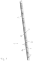
- FIG. 1 shows a solar system 1 with three module tables 2a, 2b, 2c.
- Each of the three module tables 2a to 2c carries a plurality of photovoltaic solar modules 3.
- Each of the three module tables 2a to 2c is coupled to four gear elements in the form of gear segments 4. This coupling between module tables 2a to 2c and the gear segments 4 means that pivoting of the gear segments 4 causes the module tables 2a to 2c to pivot in order to guide the individual solar modules 3 along the path of the sun.
- the gear segments 4 are driven by an electrically driven drive shaft 5 and thus pivoted.
- the drive shaft 5 is driven by a gear unit 6 and drives all three module tables 2a to 2c.
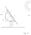
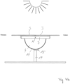
- FIGS 2 and 3 show a section of the solar system 1 in the area of a gear segment 4.
- the solar modules adjoining the solar modules 3 shown have been omitted.
- the gear segment 4 is attached to a cross yoke 7, which serves as the cross brace of the module table 2a shown here.
- the gear segment 4 is in this case screwed to the cross yoke 7.
- the gear segment 4 and thus also the cross yoke 7 can be pivoted about the transverse axis A of the cross yoke 7.
- an actuating element 8 is integrated into the drive shaft 5.
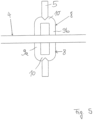
- the actuating element 8 is also in the Figures 5 , 6a and 6b shown enlarged.
- the actuating element 8 is designed as a type of elongated frame with two actuating pins 9a, 9b arranged parallel to one another.
- the actuating pins 9a and 9b are connected to one another in one piece via two connecting sections 10.
- the actuating pins 9a and 9b are arranged at a distance from one another in such a way that they engage in the toothing 11 of the gear segment 4 and can cause the gear segment 4 to rotate (pivot) through the rotational movement of the drive shaft.
- the module table 2a is also pivoted in one direction or the other.
- the interaction between the actuating element 8 and the toothing 11 of the gear segment 4 is shown in the Figures 6a and 6b illustrated in more detail.
- Both actuating pins 9a and 9b are located in a tooth gap 12a, 12b of the toothing 11.
- the tooth gaps 12a and 12b are arranged adjacent to each other.
- the teeth of the toothing 11 are identified by the reference numeral 13.
- the drive shaft 5 rotates clockwise.
- the actuating pin 9b leaves the tooth gap 12b and is initially pivoted by the rotational movement of the drive shaft so that it is located directly below the tooth gap 12a (see small arrow).
- the actuating pin 9a moves deeper into the tooth gap 12a.
- Figure 6b shows.
- the actuating pin 9b is now pivoted further in the direction of the tooth gap 12c.
- the actuating pin 9a is moved further out of the tooth gap 12a.
- the drive shaft can be coupled with a wind sensor, for example. This wind sensor can then lock the drive shaft 5 in the position specified in Figure 6a shown position.
- a further rotation of the drive shaft 5 in a clockwise direction ultimately leads to the module tables or solar modules 3 in the Figure 4c shown evening position.
- the drive shaft 5 must now be moved anti-clockwise. Such a rotation of the drive shaft 5 causes the gear segment 4 and thus the module table coupled to it to pivot or rotate clockwise.
- gear segments 4 as well as the drive shaft 5 with the actuating elements 8 are made of steel.
- the longitudinal axis L of the drive shaft 5 extends through the toothing 11 of the gear segment 4. This has the advantage that the position of the longitudinal axis L of the drive shaft 5 does not have to be changed in order to move the actuating element to the position shown in order to achieve an optimal blocking of the gear segment 4.
- Figure 6a shown position
- the solar system 1 has vertical posts 14 for supporting the module tables 2a to 2c.
- the number of these vertical posts 14 corresponds to the number of gear segments 4.
- the vertical posts 14 are also all arranged in the area of the gear segments 4.
- retaining plates 15 are arranged on the vertical posts 14. These retaining plates 15 serve to hold the drive shaft 5, which passes through the retaining plates 15.
- the retaining plates 15 absorb forces acting on the drive shaft 5 and transfer them to the foundation in the form of the vertical posts 14. The forces mentioned are in particular forces which arise from high wind loads and are transferred from the gear segments 4 to the drive shaft 5.
- the stability of the entire system 1 is comparable to a fixed solar system. This means that even very high wind loads can act on the solar system 1 without damaging it.
- the elements of the solar system 1 according to the invention shown in the drawings can also be designed differently. It is conceivable that the actuating element is constructed from two metal sheets, e.g. disc-shaped metal sheets, which are connected via two fastening pins arranged parallel to one another. The two metal sheets can then be welded, for example, to one end of a drive shaft section.
- two metal sheets e.g. disc-shaped metal sheets
Landscapes
- Engineering & Computer Science (AREA)
- General Engineering & Computer Science (AREA)
- Mechanical Engineering (AREA)
- Sustainable Development (AREA)
- Life Sciences & Earth Sciences (AREA)
- Physics & Mathematics (AREA)
- Sustainable Energy (AREA)
- Thermal Sciences (AREA)
- Chemical & Material Sciences (AREA)
- Combustion & Propulsion (AREA)
- Photovoltaic Devices (AREA)
- Wind Motors (AREA)
- Roof Covering Using Slabs Or Stiff Sheets (AREA)
Claims (6)
- Installation solaire (1) ayant au moins une table de module (2a, 2b, 2c) pivotable qui supporte au moins une module solaire (3) photovoltaïque, de préférence des modules solaires (3) photovoltaïques multiples, et qui est couplée à au moins un élément de roue dentée (4) pivotable autour d'un axe (A) de telle manière que le pivotement de l'élément de roue dentée (4) fait que la table de module (2a à 2c) est pivotée afin que les modules solaires (3) suivent le mouvement du Soleil, l'élément de roue dentée (4) étant entraîné et donc pivoté par un arbre d'entraînement (5) entraîné électriquement, au moins un élément d'actionnement (8) étant intégré dans l'arbre d'entraînement (5), l'élément de roue dentée (4) étant à la fois entraîné et bloqué par l'élément d'actionnement (8), caractérisée en ce que l'élément d'actionnement (8) s'engage dans les dents (11) de l'élément de roue dentée (4) afin d'entraîner ou afin de bloquer l'élément de roue dentée (4), caractérisée en ce que l'élément d'actionnement (8) comprend au moins deux goupilles d'actionnement (9a, 9b) qui sont disposées essentiellement en parallèle l'une à l'autre et s'engagent dans les dents (11) de l'élément de roue dentée (4) afin d'entraîner (pivoter) ou afin de bloquer l'élément de roue dentée (4), de préférence tous les deux goupilles d'actionnement (9a, 9b) chacune restant dans un espace de dents, notamment dans des espaces de dents (12a, 12b, 12c) adjacents, de dents (11) de l'élément de roue dentée (4) et y restant pour bloquer l'élément de roue dentée (4).
- Installation solaire selon la revendication 1, caractérisée en ce que l'élément de roue dentée est un segment de roue dentée (4).
- Installation solaire selon l'une quelconque des revendications précédentes, caractérisée en ce que l'élément d'actionnement (8) est une bague ou un cadre angulaires ou ronds.
- Installation solaire selon l'une quelconque des revendications précédentes, caractérisée en ce que l'au moins une table de module (2a, 2b, 2c) est montée sur l'au moins un élément de roue dentée (4).
- Installation solaire selon l'une quelconque des revendications précédentes, caractérisée en ce que l'axe longitudinal (L) de l'arbre d'entraînement (5), autour duquel il tourne, s'étende à travers les dents (11) de l'au moins un élément de roue dentée (4).
- Installation solaire selon l'une quelconque des revendications précédentes, caractérisée en ce que l'installation solaire comprend des poteaux verticaux (14) pour un montage élevé de l'au moins une table de module (2a, 2b, 2c), les poteaux verticaux (14) ayant au moins partiellement des plaques de support (15) pour supporter l'arbre d'entraînement (5).
Priority Applications (1)
| Application Number | Priority Date | Filing Date | Title |
|---|---|---|---|
| MA68020A MA68020B1 (fr) | 2018-05-30 | 2019-04-11 | Installation solaire ayant un table de modules pivotantes et fixables |
Applications Claiming Priority (2)
| Application Number | Priority Date | Filing Date | Title |
|---|---|---|---|
| DE202018103053.1U DE202018103053U1 (de) | 2018-05-30 | 2018-05-30 | Solaranlage mit verschwenkbarem und feststellbarem Modultisch |
| PCT/EP2019/059300 WO2019228703A1 (fr) | 2018-05-30 | 2019-04-11 | Installation solaire ayant un table de modules pivotantes et fixables |
Publications (2)
| Publication Number | Publication Date |
|---|---|
| EP3804121A1 EP3804121A1 (fr) | 2021-04-14 |
| EP3804121B1 true EP3804121B1 (fr) | 2024-10-02 |
Family
ID=62716740
Family Applications (1)
| Application Number | Title | Priority Date | Filing Date |
|---|---|---|---|
| EP19719191.9A Active EP3804121B1 (fr) | 2018-05-30 | 2019-04-11 | Installation solaire ayant un table de modules pivotantes et fixables |
Country Status (15)
| Country | Link |
|---|---|
| US (1) | US11689151B2 (fr) |
| EP (1) | EP3804121B1 (fr) |
| JP (1) | JP7227276B2 (fr) |
| CN (1) | CN112204876A (fr) |
| AU (1) | AU2019278299B2 (fr) |
| CL (1) | CL2020002968A1 (fr) |
| DE (1) | DE202018103053U1 (fr) |
| ES (1) | ES2994326T3 (fr) |
| IL (1) | IL279002B2 (fr) |
| JO (1) | JOP20200262B1 (fr) |
| MA (1) | MA68020B1 (fr) |
| MX (1) | MX2020011863A (fr) |
| PT (1) | PT3804121T (fr) |
| WO (1) | WO2019228703A1 (fr) |
| ZA (1) | ZA202006486B (fr) |
Families Citing this family (10)
| Publication number | Priority date | Publication date | Assignee | Title |
|---|---|---|---|---|
| DE102018002460A1 (de) | 2018-03-23 | 2019-09-26 | Schletter International B.V. | Antriebsanordnung |
| ES2982495T3 (es) * | 2018-03-23 | 2024-10-16 | Schletter Int B V | Unidad de giro para un dispositivo de seguimiento de módulos solares |
| DE102019003426B3 (de) * | 2019-05-09 | 2020-07-16 | SPORK & PARTNERS ENGlNEERlNG CONSULTING | Nachführvorrichtung |
| US11711052B2 (en) | 2021-02-09 | 2023-07-25 | Array Technologies, Inc. | Geared drive system providing intermittent motion |
| USD990288S1 (en) * | 2021-04-09 | 2023-06-27 | Dongguan Shichang Metals Factory Ltd. | Cross brace for a tabletop |
| USD1006594S1 (en) | 2021-06-14 | 2023-12-05 | Dongguan Shichang Metals Factory Ltd. | Cross brace for a tabletop |
| CN113718983B (zh) * | 2021-08-17 | 2022-12-20 | 阜新北方电力工程有限责任公司 | 一种光伏一体化的玻璃化建筑墙体 |
| EP4152599A1 (fr) | 2021-09-21 | 2023-03-22 | IDEEMATEC Deutschland GmbH | Dispositif de suivi pour panneaux solaires |
| US12355392B2 (en) * | 2022-10-20 | 2025-07-08 | Sun And Steel Solar Llc | Drive system for single axis solar tracking |
| ES3058356T3 (es) * | 2023-06-14 | 2026-03-10 | Trina Solar Spain S L U | Sistema de bloqueo pasivo para seguidor solar |
Citations (8)
| Publication number | Priority date | Publication date | Assignee | Title |
|---|---|---|---|---|
| DE328666C (de) * | 1917-06-14 | 1920-11-03 | Singer Mfg Co | Vorrichtung zur Umwandlung drehender Bewegung in schrittweise Bewegung |
| US2618187A (en) * | 1950-08-08 | 1952-11-18 | Keller Tool Co | Power-driven gear operated wrench |
| WO1979000930A1 (fr) * | 1978-04-14 | 1979-11-15 | Romanet Les Fils Sarl | Dispositif d'entrainement d'une roue dentee par un moteur pas a pas bipolaire |
| US4265555A (en) * | 1978-09-14 | 1981-05-05 | Gottfried Burkhardt | Dual pitch carriage drive mechanism |
| US20080066985A1 (en) * | 2006-09-14 | 2008-03-20 | Sun, Ho-Wei | Control device for periodical driving system |
| US20100139645A1 (en) * | 2008-12-01 | 2010-06-10 | Sun-A-Ray, Llc. | Balanced support and solar tracking system for panels of photovoltaic cells |
| US20160365830A1 (en) * | 2015-05-18 | 2016-12-15 | Alion Energy, Inc. | Systems and methods for rotating photovoltaic modules |
| WO2019179781A1 (fr) * | 2018-03-23 | 2019-09-26 | Schletter International B.V. | Système d'entraînement |
Family Cites Families (17)
| Publication number | Priority date | Publication date | Assignee | Title |
|---|---|---|---|---|
| US8459249B2 (en) * | 2007-06-15 | 2013-06-11 | Ronald P. Corio | Single axis solar tracking system |
| US20110108112A1 (en) | 2008-01-31 | 2011-05-12 | Jin Woo Hong | Device for tracking location of sun |
| US9631840B2 (en) * | 2008-06-12 | 2017-04-25 | Ronald P. Corio | Single axis solar tracking system |
| ES2350071B1 (es) * | 2009-05-11 | 2011-10-18 | Soltec Energias Renovables | Seguidor solar de un solo eje e instalacion de energia solar. |
| US20160093756A9 (en) | 2009-11-24 | 2016-03-31 | Charles Silver | Solar Photovoltaic Support and Tracking System with vertical adjustment capability |
| JP5569447B2 (ja) | 2011-03-24 | 2014-08-13 | 大同特殊鋼株式会社 | 太陽光発電装置 |
| DE102012207749A1 (de) * | 2012-05-09 | 2013-11-14 | Schaeffler Technologies AG & Co. KG | Lageranordnung sowie Parabolrinnenkollektor |
| US20140174499A1 (en) | 2012-11-13 | 2014-06-26 | Brian M. Fitzgerald | Solar thermal heliostat |
| WO2015113445A1 (fr) * | 2014-01-30 | 2015-08-06 | 浙江同景新能源集团有限公司 | Système amélioré de poursuite et de commande photovoltaïque |
| MX363114B (es) | 2014-02-19 | 2019-03-08 | Array Tech Inc | Dispositivos del limitador de torsión, sistemas y métodos y rastreadores solares que incorporan limitadores de torsión. |
| FR3028113B1 (fr) * | 2014-11-05 | 2016-12-30 | Optimum Tracker | Systeme de support suiveur mono-axe pour capteur solaire |
| AU2015397096B2 (en) | 2015-06-01 | 2021-04-01 | Habdank Pv-Montagesysteme Gmbh & Co. Kg | Tracking device |
| DE202015009590U1 (de) | 2015-06-01 | 2018-06-25 | Habdank Pv-Montagesysteme Gmbh & Co. Kg | Nachführvorrichtung |
| US11035591B2 (en) * | 2015-10-13 | 2021-06-15 | Corosolar Llc | Bearing assembly for solar trackers |
| MX2019000053A (es) * | 2016-07-08 | 2019-05-02 | Alion Energy Inc | Sistemas y métodos para montaje y bloqueo de paneles solares de forma giratoria. |
| CN206135796U (zh) | 2016-11-08 | 2017-04-26 | 厦门智同方达科技有限公司 | 一种太阳能发电系统及其传动装置 |
| ES2765414T3 (es) * | 2017-02-17 | 2020-06-09 | Nexans Solar Tech | Seguidor solar con acoplamiento cinemático |
-
2018
- 2018-05-30 DE DE202018103053.1U patent/DE202018103053U1/de active Active
-
2019
- 2019-04-11 CN CN201980032990.8A patent/CN112204876A/zh active Pending
- 2019-04-11 IL IL279002A patent/IL279002B2/en unknown
- 2019-04-11 JP JP2020561902A patent/JP7227276B2/ja active Active
- 2019-04-11 EP EP19719191.9A patent/EP3804121B1/fr active Active
- 2019-04-11 US US17/057,729 patent/US11689151B2/en active Active
- 2019-04-11 MA MA68020A patent/MA68020B1/fr unknown
- 2019-04-11 PT PT197191919T patent/PT3804121T/pt unknown
- 2019-04-11 AU AU2019278299A patent/AU2019278299B2/en active Active
- 2019-04-11 WO PCT/EP2019/059300 patent/WO2019228703A1/fr not_active Ceased
- 2019-04-11 ES ES19719191T patent/ES2994326T3/es active Active
- 2019-04-11 MX MX2020011863A patent/MX2020011863A/es unknown
-
2020
- 2020-10-14 JO JOJO/P/2020/0262A patent/JOP20200262B1/ar active
- 2020-10-19 ZA ZA2020/06486A patent/ZA202006486B/en unknown
- 2020-11-16 CL CL2020002968A patent/CL2020002968A1/es unknown
Patent Citations (8)
| Publication number | Priority date | Publication date | Assignee | Title |
|---|---|---|---|---|
| DE328666C (de) * | 1917-06-14 | 1920-11-03 | Singer Mfg Co | Vorrichtung zur Umwandlung drehender Bewegung in schrittweise Bewegung |
| US2618187A (en) * | 1950-08-08 | 1952-11-18 | Keller Tool Co | Power-driven gear operated wrench |
| WO1979000930A1 (fr) * | 1978-04-14 | 1979-11-15 | Romanet Les Fils Sarl | Dispositif d'entrainement d'une roue dentee par un moteur pas a pas bipolaire |
| US4265555A (en) * | 1978-09-14 | 1981-05-05 | Gottfried Burkhardt | Dual pitch carriage drive mechanism |
| US20080066985A1 (en) * | 2006-09-14 | 2008-03-20 | Sun, Ho-Wei | Control device for periodical driving system |
| US20100139645A1 (en) * | 2008-12-01 | 2010-06-10 | Sun-A-Ray, Llc. | Balanced support and solar tracking system for panels of photovoltaic cells |
| US20160365830A1 (en) * | 2015-05-18 | 2016-12-15 | Alion Energy, Inc. | Systems and methods for rotating photovoltaic modules |
| WO2019179781A1 (fr) * | 2018-03-23 | 2019-09-26 | Schletter International B.V. | Système d'entraînement |
Also Published As
| Publication number | Publication date |
|---|---|
| ES2994326T3 (en) | 2025-01-22 |
| CL2020002968A1 (es) | 2021-07-30 |
| JOP20200262B1 (ar) | 2024-12-22 |
| CN112204876A (zh) | 2021-01-08 |
| JP2021525053A (ja) | 2021-09-16 |
| JP7227276B2 (ja) | 2023-02-21 |
| US20210211089A1 (en) | 2021-07-08 |
| AU2019278299B2 (en) | 2023-05-11 |
| EP3804121A1 (fr) | 2021-04-14 |
| BR112020023496A2 (pt) | 2021-03-30 |
| CA3096967A1 (fr) | 2019-12-05 |
| WO2019228703A1 (fr) | 2019-12-05 |
| PT3804121T (pt) | 2024-12-31 |
| AU2019278299A1 (en) | 2020-11-05 |
| ZA202006486B (en) | 2022-01-26 |
| MX2020011863A (es) | 2021-02-22 |
| MA68020B1 (fr) | 2024-10-31 |
| US11689151B2 (en) | 2023-06-27 |
| DE202018103053U1 (de) | 2018-06-08 |
| IL279002B1 (en) | 2023-12-01 |
| JOP20200262A1 (ar) | 2020-10-14 |
| IL279002B2 (en) | 2024-04-01 |
| IL279002A (en) | 2021-01-31 |
Similar Documents
| Publication | Publication Date | Title |
|---|---|---|
| EP3804121A1 (fr) | Installation solaire ayant un table de modules pivotantes et fixables | |
| EP2843322B1 (fr) | Dispositif de support et de suivi de la position du soleil d'unités de poursuite pour panneaux solaires | |
| EP2885587B1 (fr) | Construction porteuse pour modules solaire | |
| EP2724382B1 (fr) | Support pour modules pv | |
| EP3769018B1 (fr) | Unité de pivotement pour un dispositif de poursuite pour des modules solaires | |
| EP0041136A1 (fr) | Entraînement orientable pour éléments pivotants de machines, en particulier pour manipulateurs | |
| WO2014076185A1 (fr) | Système de stabilisation | |
| DE102020107794A1 (de) | Vorrichtung zum Verriegeln einer Nachführeinrichtung für eine PV-Anlage und Verfahren zum Entriegeln einer Nachführeinrichtung | |
| DE102010014087A1 (de) | Vorrichtung zur zweiachsigen Verstellung einer Anlage, insbesondere einer Solarpaneel-Einheit | |
| EP2963357A1 (fr) | Dispositif suiveur pour modules solaires | |
| EP3752694B1 (fr) | Dispositif de stationnement de voiture | |
| EP2882273B1 (fr) | Outil pour le travail du sol comprenant un dispositif de production d'un remous, de collecte ou de travail de terre ou de paillis | |
| EP3966930B1 (fr) | Dispositif de poursuite | |
| EP2514985A1 (fr) | Concept de fixation pour un palier à roulement | |
| WO2016046224A1 (fr) | Mât articulé | |
| DE102011007635B4 (de) | Sicherungskonzept für ein Wälzlager | |
| EP4473254B1 (fr) | Dispositif de suivi pour modules solaires | |
| DE102011120071A1 (de) | Fahrbare Lagereinrichtung für eine mobile Dachkonstruktion | |
| WO2016046221A1 (fr) | Bras de mât à mécanisme à levier | |
| AT518917B1 (de) | Absturzsicherung | |
| EP4103329B1 (fr) | Bielle de réaction destinée à intercepter un couple d'entraînement et ensemble rouleaux muni d'une bielle de réaction | |
| EP2295696A1 (fr) | Portail multi-sections | |
| DE69720627T2 (de) | Arretierung für Rolladen, mit einer frei drehbaren Wickelwelle | |
| EP0599238B1 (fr) | Dispositif d'actionnement pour frein de stationnement de véhicules ferroviaires | |
| EP2249103A2 (fr) | Système de suivi de la position du soleil sur un axe pour une multitude de modules de conversion d'énergie |
Legal Events
| Date | Code | Title | Description |
|---|---|---|---|
| STAA | Information on the status of an ep patent application or granted ep patent |
Free format text: STATUS: UNKNOWN |
|
| STAA | Information on the status of an ep patent application or granted ep patent |
Free format text: STATUS: THE INTERNATIONAL PUBLICATION HAS BEEN MADE |
|
| PUAI | Public reference made under article 153(3) epc to a published international application that has entered the european phase |
Free format text: ORIGINAL CODE: 0009012 |
|
| STAA | Information on the status of an ep patent application or granted ep patent |
Free format text: STATUS: REQUEST FOR EXAMINATION WAS MADE |
|
| 17P | Request for examination filed |
Effective date: 20201001 |
|
| AK | Designated contracting states |
Kind code of ref document: A1 Designated state(s): AL AT BE BG CH CY CZ DE DK EE ES FI FR GB GR HR HU IE IS IT LI LT LU LV MC MK MT NL NO PL PT RO RS SE SI SK SM TR |
|
| AX | Request for extension of the european patent |
Extension state: BA ME |
|
| DAX | Request for extension of the european patent (deleted) | ||
| RAV | Requested validation state of the european patent: fee paid |
Extension state: TN Effective date: 20201001 Extension state: MA Effective date: 20201001 |
|
| STAA | Information on the status of an ep patent application or granted ep patent |
Free format text: STATUS: EXAMINATION IS IN PROGRESS |
|
| 17Q | First examination report despatched |
Effective date: 20220831 |
|
| GRAP | Despatch of communication of intention to grant a patent |
Free format text: ORIGINAL CODE: EPIDOSNIGR1 |
|
| STAA | Information on the status of an ep patent application or granted ep patent |
Free format text: STATUS: GRANT OF PATENT IS INTENDED |
|
| RIC1 | Information provided on ipc code assigned before grant |
Ipc: H02S 20/10 20140101ALI20221116BHEP Ipc: F24S 25/10 20180101ALI20221116BHEP Ipc: F24S 30/425 20180101ALI20221116BHEP Ipc: H02S 20/32 20140101AFI20221116BHEP |
|
| INTG | Intention to grant announced |
Effective date: 20221206 |
|
| TPAC | Observations filed by third parties |
Free format text: ORIGINAL CODE: EPIDOSNTIPA |
|
| GRAJ | Information related to disapproval of communication of intention to grant by the applicant or resumption of examination proceedings by the epo deleted |
Free format text: ORIGINAL CODE: EPIDOSDIGR1 |
|
| STAA | Information on the status of an ep patent application or granted ep patent |
Free format text: STATUS: EXAMINATION IS IN PROGRESS |
|
| INTC | Intention to grant announced (deleted) | ||
| TPAC | Observations filed by third parties |
Free format text: ORIGINAL CODE: EPIDOSNTIPA |
|
| TPAC | Observations filed by third parties |
Free format text: ORIGINAL CODE: EPIDOSNTIPA |
|
| GRAP | Despatch of communication of intention to grant a patent |
Free format text: ORIGINAL CODE: EPIDOSNIGR1 |
|
| STAA | Information on the status of an ep patent application or granted ep patent |
Free format text: STATUS: GRANT OF PATENT IS INTENDED |
|
| INTG | Intention to grant announced |
Effective date: 20240430 |
|
| GRAS | Grant fee paid |
Free format text: ORIGINAL CODE: EPIDOSNIGR3 |
|
| GRAA | (expected) grant |
Free format text: ORIGINAL CODE: 0009210 |
|
| STAA | Information on the status of an ep patent application or granted ep patent |
Free format text: STATUS: THE PATENT HAS BEEN GRANTED |
|
| P01 | Opt-out of the competence of the unified patent court (upc) registered |
Free format text: CASE NUMBER: APP_47653/2024 Effective date: 20240821 |
|
| AK | Designated contracting states |
Kind code of ref document: B1 Designated state(s): AL AT BE BG CH CY CZ DE DK EE ES FI FR GB GR HR HU IE IS IT LI LT LU LV MC MK MT NL NO PL PT RO RS SE SI SK SM TR |
|
| REG | Reference to a national code |
Ref country code: GB Ref legal event code: FG4D Free format text: NOT ENGLISH Ref country code: TN Ref legal event code: VAGR Ref document number: TN/P/2024/000439 Country of ref document: TN |
|
| REG | Reference to a national code |
Ref country code: CH Ref legal event code: EP |
|
| REG | Reference to a national code |
Ref country code: DE Ref legal event code: R096 Ref document number: 502019012220 Country of ref document: DE |
|
| REG | Reference to a national code |
Ref country code: IE Ref legal event code: FG4D Free format text: LANGUAGE OF EP DOCUMENT: GERMAN |
|
| REG | Reference to a national code |
Ref country code: MA Ref legal event code: VAGR Ref document number: 68020 Country of ref document: MA Kind code of ref document: B1 |
|
| REG | Reference to a national code |
Ref country code: GR Ref legal event code: EP Ref document number: 20240402601 Country of ref document: GR Effective date: 20241209 |
|
| REG | Reference to a national code |
Ref country code: PT Ref legal event code: SC4A Ref document number: 3804121 Country of ref document: PT Date of ref document: 20241231 Kind code of ref document: T Free format text: AVAILABILITY OF NATIONAL TRANSLATION Effective date: 20241223 |
|
| REG | Reference to a national code |
Ref country code: ES Ref legal event code: FG2A Ref document number: 2994326 Country of ref document: ES Kind code of ref document: T3 Effective date: 20250122 |
|
| REG | Reference to a national code |
Ref country code: LT Ref legal event code: MG9D |
|
| REG | Reference to a national code |
Ref country code: NL Ref legal event code: MP Effective date: 20241002 |
|
| PG25 | Lapsed in a contracting state [announced via postgrant information from national office to epo] |
Ref country code: NL Free format text: LAPSE BECAUSE OF FAILURE TO SUBMIT A TRANSLATION OF THE DESCRIPTION OR TO PAY THE FEE WITHIN THE PRESCRIBED TIME-LIMIT Effective date: 20241002 |
|
| PG25 | Lapsed in a contracting state [announced via postgrant information from national office to epo] |
Ref country code: NL Free format text: LAPSE BECAUSE OF FAILURE TO SUBMIT A TRANSLATION OF THE DESCRIPTION OR TO PAY THE FEE WITHIN THE PRESCRIBED TIME-LIMIT Effective date: 20241002 |
|
| PG25 | Lapsed in a contracting state [announced via postgrant information from national office to epo] |
Ref country code: HR Free format text: LAPSE BECAUSE OF FAILURE TO SUBMIT A TRANSLATION OF THE DESCRIPTION OR TO PAY THE FEE WITHIN THE PRESCRIBED TIME-LIMIT Effective date: 20241002 Ref country code: IS Free format text: LAPSE BECAUSE OF FAILURE TO SUBMIT A TRANSLATION OF THE DESCRIPTION OR TO PAY THE FEE WITHIN THE PRESCRIBED TIME-LIMIT Effective date: 20250202 |
|
| PG25 | Lapsed in a contracting state [announced via postgrant information from national office to epo] |
Ref country code: FI Free format text: LAPSE BECAUSE OF FAILURE TO SUBMIT A TRANSLATION OF THE DESCRIPTION OR TO PAY THE FEE WITHIN THE PRESCRIBED TIME-LIMIT Effective date: 20241002 |
|
| PG25 | Lapsed in a contracting state [announced via postgrant information from national office to epo] |
Ref country code: NO Free format text: LAPSE BECAUSE OF FAILURE TO SUBMIT A TRANSLATION OF THE DESCRIPTION OR TO PAY THE FEE WITHIN THE PRESCRIBED TIME-LIMIT Effective date: 20250102 |
|
| PG25 | Lapsed in a contracting state [announced via postgrant information from national office to epo] |
Ref country code: LV Free format text: LAPSE BECAUSE OF FAILURE TO SUBMIT A TRANSLATION OF THE DESCRIPTION OR TO PAY THE FEE WITHIN THE PRESCRIBED TIME-LIMIT Effective date: 20241002 |
|
| PG25 | Lapsed in a contracting state [announced via postgrant information from national office to epo] |
Ref country code: CZ Free format text: LAPSE BECAUSE OF FAILURE TO SUBMIT A TRANSLATION OF THE DESCRIPTION OR TO PAY THE FEE WITHIN THE PRESCRIBED TIME-LIMIT Effective date: 20241002 Ref country code: PL Free format text: LAPSE BECAUSE OF FAILURE TO SUBMIT A TRANSLATION OF THE DESCRIPTION OR TO PAY THE FEE WITHIN THE PRESCRIBED TIME-LIMIT Effective date: 20241002 |
|
| PG25 | Lapsed in a contracting state [announced via postgrant information from national office to epo] |
Ref country code: RS Free format text: LAPSE BECAUSE OF FAILURE TO SUBMIT A TRANSLATION OF THE DESCRIPTION OR TO PAY THE FEE WITHIN THE PRESCRIBED TIME-LIMIT Effective date: 20250102 |
|
| REG | Reference to a national code |
Ref country code: DE Ref legal event code: R026 Ref document number: 502019012220 Country of ref document: DE |
|
| PG25 | Lapsed in a contracting state [announced via postgrant information from national office to epo] |
Ref country code: SM Free format text: LAPSE BECAUSE OF FAILURE TO SUBMIT A TRANSLATION OF THE DESCRIPTION OR TO PAY THE FEE WITHIN THE PRESCRIBED TIME-LIMIT Effective date: 20241002 |
|
| PLBI | Opposition filed |
Free format text: ORIGINAL CODE: 0009260 |
|
| PGFP | Annual fee paid to national office [announced via postgrant information from national office to epo] |
Ref country code: DE Payment date: 20250618 Year of fee payment: 7 |
|
| PG25 | Lapsed in a contracting state [announced via postgrant information from national office to epo] |
Ref country code: DK Free format text: LAPSE BECAUSE OF FAILURE TO SUBMIT A TRANSLATION OF THE DESCRIPTION OR TO PAY THE FEE WITHIN THE PRESCRIBED TIME-LIMIT Effective date: 20241002 |
|
| PGFP | Annual fee paid to national office [announced via postgrant information from national office to epo] |
Ref country code: ES Payment date: 20250519 Year of fee payment: 7 |
|
| PGFP | Annual fee paid to national office [announced via postgrant information from national office to epo] |
Ref country code: IT Payment date: 20250430 Year of fee payment: 7 |
|
| PLAX | Notice of opposition and request to file observation + time limit sent |
Free format text: ORIGINAL CODE: EPIDOSNOBS2 |
|
| PG25 | Lapsed in a contracting state [announced via postgrant information from national office to epo] |
Ref country code: EE Free format text: LAPSE BECAUSE OF FAILURE TO SUBMIT A TRANSLATION OF THE DESCRIPTION OR TO PAY THE FEE WITHIN THE PRESCRIBED TIME-LIMIT Effective date: 20241002 |
|
| PGFP | Annual fee paid to national office [announced via postgrant information from national office to epo] |
Ref country code: FR Payment date: 20250422 Year of fee payment: 7 |
|
| PGFP | Annual fee paid to national office [announced via postgrant information from national office to epo] |
Ref country code: GR Payment date: 20250416 Year of fee payment: 7 Ref country code: BG Payment date: 20250415 Year of fee payment: 7 |
|
| PG25 | Lapsed in a contracting state [announced via postgrant information from national office to epo] |
Ref country code: RO Free format text: LAPSE BECAUSE OF FAILURE TO SUBMIT A TRANSLATION OF THE DESCRIPTION OR TO PAY THE FEE WITHIN THE PRESCRIBED TIME-LIMIT Effective date: 20241002 |
|
| PG25 | Lapsed in a contracting state [announced via postgrant information from national office to epo] |
Ref country code: SK Free format text: LAPSE BECAUSE OF FAILURE TO SUBMIT A TRANSLATION OF THE DESCRIPTION OR TO PAY THE FEE WITHIN THE PRESCRIBED TIME-LIMIT Effective date: 20241002 |
|
| PGFP | Annual fee paid to national office [announced via postgrant information from national office to epo] |
Ref country code: TR Payment date: 20250404 Year of fee payment: 7 |
|
| 26 | Opposition filed |
Opponent name: SL RACK GMBH Effective date: 20250701 |
|
| PG25 | Lapsed in a contracting state [announced via postgrant information from national office to epo] |
Ref country code: SE Free format text: LAPSE BECAUSE OF FAILURE TO SUBMIT A TRANSLATION OF THE DESCRIPTION OR TO PAY THE FEE WITHIN THE PRESCRIBED TIME-LIMIT Effective date: 20241002 |
|
| PLBB | Reply of patent proprietor to notice(s) of opposition received |
Free format text: ORIGINAL CODE: EPIDOSNOBS3 |
|
| VSFP | Annual fee paid to validation state [announced via postgrant information from national office to epo] |
Ref country code: MA Payment date: 20250409 Year of fee payment: 7 |
|
| REG | Reference to a national code |
Ref country code: CH Ref legal event code: H13 Free format text: ST27 STATUS EVENT CODE: U-0-0-H10-H13 (AS PROVIDED BY THE NATIONAL OFFICE) Effective date: 20251125 |
|
| PG25 | Lapsed in a contracting state [announced via postgrant information from national office to epo] |
Ref country code: LU Free format text: LAPSE BECAUSE OF NON-PAYMENT OF DUE FEES Effective date: 20250411 |
|
| PG25 | Lapsed in a contracting state [announced via postgrant information from national office to epo] |
Ref country code: MC Free format text: LAPSE BECAUSE OF FAILURE TO SUBMIT A TRANSLATION OF THE DESCRIPTION OR TO PAY THE FEE WITHIN THE PRESCRIBED TIME-LIMIT Effective date: 20241002 |
|
| GBPC | Gb: european patent ceased through non-payment of renewal fee |
Effective date: 20250411 |
|
| REG | Reference to a national code |
Ref country code: BE Ref legal event code: MM Effective date: 20250430 |
|
| PG25 | Lapsed in a contracting state [announced via postgrant information from national office to epo] |
Ref country code: GB Free format text: LAPSE BECAUSE OF NON-PAYMENT OF DUE FEES Effective date: 20250411 |
|
| PG25 | Lapsed in a contracting state [announced via postgrant information from national office to epo] |
Ref country code: BE Free format text: LAPSE BECAUSE OF NON-PAYMENT OF DUE FEES Effective date: 20250430 |
|
| PG25 | Lapsed in a contracting state [announced via postgrant information from national office to epo] |
Ref country code: CH Free format text: LAPSE BECAUSE OF NON-PAYMENT OF DUE FEES Effective date: 20250430 |
|
| PG25 | Lapsed in a contracting state [announced via postgrant information from national office to epo] |
Ref country code: IE Free format text: LAPSE BECAUSE OF NON-PAYMENT OF DUE FEES Effective date: 20250411 |
|
| VSFP | Annual fee paid to validation state [announced via postgrant information from national office to epo] |
Ref country code: MA Payment date: 20260406 Year of fee payment: 8 |
|
| PGFP | Annual fee paid to national office [announced via postgrant information from national office to epo] |
Ref country code: PT Payment date: 20260330 Year of fee payment: 8 |