EP3804502A1 - Outil électrique portable - Google Patents
Outil électrique portable Download PDFInfo
- Publication number
- EP3804502A1 EP3804502A1 EP20200900.7A EP20200900A EP3804502A1 EP 3804502 A1 EP3804502 A1 EP 3804502A1 EP 20200900 A EP20200900 A EP 20200900A EP 3804502 A1 EP3804502 A1 EP 3804502A1
- Authority
- EP
- European Patent Office
- Prior art keywords
- power tool
- air inlet
- inner housing
- motor
- handheld power
- Prior art date
- Legal status (The legal status is an assumption and is not a legal conclusion. Google has not performed a legal analysis and makes no representation as to the accuracy of the status listed.)
- Granted
Links
Images


Classifications
-
- B—PERFORMING OPERATIONS; TRANSPORTING
- B25—HAND TOOLS; PORTABLE POWER-DRIVEN TOOLS; MANIPULATORS
- B25F—COMBINATION OR MULTI-PURPOSE TOOLS NOT OTHERWISE PROVIDED FOR; DETAILS OR COMPONENTS OF PORTABLE POWER-DRIVEN TOOLS NOT PARTICULARLY RELATED TO THE OPERATIONS PERFORMED AND NOT OTHERWISE PROVIDED FOR
- B25F5/00—Details or components of portable power-driven tools not particularly related to the operations performed and not otherwise provided for
- B25F5/008—Cooling means
-
- A—HUMAN NECESSITIES
- A01—AGRICULTURE; FORESTRY; ANIMAL HUSBANDRY; HUNTING; TRAPPING; FISHING
- A01G—HORTICULTURE; CULTIVATION OF VEGETABLES, FLOWERS, RICE, FRUIT, VINES, HOPS OR SEAWEED; FORESTRY; WATERING
- A01G3/00—Cutting implements specially adapted for horticultural purposes; Delimbing standing trees
- A01G3/04—Apparatus for trimming hedges, e.g. hedge shears
- A01G3/047—Apparatus for trimming hedges, e.g. hedge shears portable
- A01G3/053—Apparatus for trimming hedges, e.g. hedge shears portable motor-driven
-
- A—HUMAN NECESSITIES
- A01—AGRICULTURE; FORESTRY; ANIMAL HUSBANDRY; HUNTING; TRAPPING; FISHING
- A01G—HORTICULTURE; CULTIVATION OF VEGETABLES, FLOWERS, RICE, FRUIT, VINES, HOPS OR SEAWEED; FORESTRY; WATERING
- A01G3/00—Cutting implements specially adapted for horticultural purposes; Delimbing standing trees
- A01G3/08—Other tools for pruning, branching or delimbing standing trees
- A01G3/085—Motor-driven saws for pruning or branching
- A01G3/086—Chain saws
-
- B—PERFORMING OPERATIONS; TRANSPORTING
- B27—WORKING OR PRESERVING WOOD OR SIMILAR MATERIAL; NAILING OR STAPLING MACHINES IN GENERAL
- B27B—SAWS FOR WOOD OR SIMILAR MATERIAL; COMPONENTS OR ACCESSORIES THEREFOR
- B27B17/00—Chain saws; Equipment therefor
Definitions
- the invention relates to a garden tool, in particular to a handheld power tool.
- Handheld power tools such as electric hedge trimmers or chain saws, are garden cutting tools, which are used for trimming various outdoor plants such as bushes, hedges and green plants.
- the handheld power tool is prone to generate a lot of heat during use and is not suitable for long-term continuous work.
- a special ventilation structure is required to dissipate heat from a motor, a gear box and a P rinted C ircuit B oard, PCB, of the handheld power tool.
- workers would use the handheld power tool in rainy and humid areas in order to rush the work.
- the handheld power tool works in rainy weather or the handheld power tool is used in a humid area
- the water may easily enter the inside of the machine through the ventilation structure, causing short circuit or burning of the PCB, motor and other parts, thus affecting the work progress and increasing the cost.
- Wood chips and dust are often generated when the handheld power tool is in operation, and they may enter into the inside of the handheld power tool through the ventilation structure, which will affect the operation of the motor.
- the object of the present disclosure is to provide a handheld power tool, which not only has a better heat dissipation effect, but also has a waterproof and dust-proof effect.
- the handheld power tool can work on rainy days and in humid areas without affecting the performance of the whole machine.
- the present disclosure provides a handheld power tool, comprising: a handle assembly; a power mechanism connected to the handle assembly; and a working mechanism connected to the power mechanism;
- the power mechanism comprises a main housing, an inner housing and a motor disposed in the inner housing, the main housing comprises a first air inlet at a side wall thereof, the inner housing comprises an opening.
- An airflow channel is located between the main housing and the inner housing, and in communication with the first air inlet, the opening and an inside of the inner housing.
- the opening is disposed at the top or bottom of the inner housing.
- a first fan is disposed on the top of the motor.
- the first fan is coaxially sleeved on an output shaft of the motor, and the motor is an external rotor motor, and the first fan is an axial fan.
- the main housing comprises a top cover located above the motor, and the first air inlet is disposed at the top of the top cover.
- the inner housing is disposed below the top cover, the top cover comprises an extension wall extending downward from the inner side of the top cover, and the extension wall is arranged between the first air inlet and the inner housing.
- a filter is disposed in the air flow channel, and the filter is disposed upstream of the opening of the inner housing for filtering dust and/or water vapor in the airflow.
- the main housing comprises a bracket disposed below the top cover, a second air inlet is arranged at the bottom of the bracket, and the second air inlet is in communication with the first air inlet in a direction extending in a direction of the output shaft of the motor.
- the power mechanism comprises a power transmission assembly installed below the bracket, the power transmission assembly comprises a bottom cover installed at the bottom of the bracket and a second fan received in the bottom cover, the bottom cover comprises a blower chamber fully surrounding the second fan.
- a heat dissipation channel is arranged at the bottom of the blower chamber and opens into the exterior of the main housing.
- the second fan is connected to an output shaft of the motor.
- a ventilation hole is arranged at the bottom of the bracket for communication between the inner housing and the blower chamber.
- At least two heat dissipation fins are arranged on the side of the bottom cover close to a blade assembly.
- a heat dissipation channel is arranged between two adjacent heat dissipation fins.
- the blower chamber is fully surrounded by two heat dissipation fins. One end of the heat dissipation channel is in communication with the blower chamber and the other end is in communication with the exterior of the main housing.
- the heat dissipation channel is arranged at an end of the bottom cover opposite to the blade assembly.
- a third air inlet is arranged at the bottom of the blower chamber.
- the heat dissipation channel extends in the width direction of the bottom cover.
- the third air inlet extends in the direction of the length of the bottom cover.
- the power mechanism comprises a circuit board electrically connected to the motor.
- the circuit board is arranged below the top cover on the same side of the main housing as the first air inlet.
- the handheld power tool may be a hedge trimmer or a chainsaw.
- the second fan may be a centrifugal fan.
- the beneficial effect of the present disclosure is that the handheld power tool of the present disclosure comprises a first air inlet at the main housing and an opening at the inner housing, so that external air can enter the motor room through the first air inlet, and then enters the inside of the motor through the opening.
- the handheld power tool of the present disclosure not only has a better heat dissipation effect, but also has waterproof and dust-proof effects.
- the handheld power tool can work on rainy days and in humid areas without affecting the performance of the whole machine.
- a hedge trimmer 100 is taken as an example for the description. It should be understood that the power tool comprises grass trimmers, chainsaws, air blowers and the like.
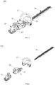
- the hedge trimmer 100 in a first embodiment of the present disclosure comprises a handle assembly 10, a power mechanism 20 connected with the handle assembly 10, and a working mechanism connected to the power mechanism 20.
- the working mechanism is a blade assembly 30, which is used as an example in the description.
- the handle assembly 10 comprises a main handle 11, an auxiliary handle 12, and a protective plate 13.
- the main handle 11 is a gripable handle structure with a cavity. Switches and the like for operation are all disposed on the main handle 11.
- the main handle 11 and the auxiliary handle 12 are respectively arranged at both ends of the power mechanism 20, and the auxiliary handle 12 is disposed near the blade assembly 30, which is convenient for users to hold and start protection safely.
- the protective plate 13 is integrally arranged with the auxiliary handle 12.
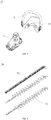
- the blade assembly 30 comprises a pair of cutting blades 31 and a blade supporting member 32.
- the pair of cutting blades 31 are releasable connected with the power mechanism 20.
- the pair of cutting blades 3 are driven to perform a cutting operation by the power mechanism 20.
- the blade supporting member 32 is fixedly arranged at a middle position of the cutting blades 31 in a width direction of the blades and is located above the pair of cutting blades 31.
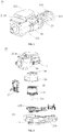
- the power mechanism 20 comprises a main housing 21, a motor 22 received in a motor room 210 of the main housing 21, an inner housing 24 covering the motor 22 and a power transmission assembly 23 installed below the main housing 21.
- the main housing 21 comprises a top cover 211 covering the top of the motor 22 and a bracket 212 located below the top cover 211.
- the motor room 210 is located below the top cover 211 and is defined by the top cover 211 and the inner housing 24 together.
- the motor 22 is preferably an external rotor motor.
- a first air inlet 2110 is arranged at the top of the top cover 211, and the first air inlet 2110 is located on the side wall of the main housing 21. Specifically, the first air inlet 2110 is located at the top of the rear wall of the top cover 211, and the rear wall is facing the rear handle 11, so that the outside air can enter inside of the top cover 211 through the first air inlet 2110 in a horizontal direction.
- the first air inlet 2110 may also be arranged at the top of the other side walls of the top cover 211, or the first air inlet 2110 may be arranged both on the side wall and the rear wall of the top cover 211, which may be determined according to actual conditions and is not limited thereto.
- the inner housing 24 is arranged below the top cover 211 and is located adjacent to the first air inlet 2110.
- the top cover 211 comprises an extension wall 25 positioned between the first air inlet 2110 and the inner housing 24, and the extension wall 25 extends vertically downward from the inner wall of the top cover 211.
- the extension wall 25 extends to the middle position of the inner housing 24 and is not in contact with the inner housing 24 in the vertical direction. That is, the extension wall 25 extends vertically downward from the inner wall of the top cover 211 to half the height of the inner housing 24.
- an airflow channel 251 is located between the main housing 21 and the inner housing 24 and also between the extension wall 25 and the inner housing 24, so that after external air enters through the first air inlet 2110, it will flow into the space (that is, into the motor room 210) defined by the inner housing 24 and the top cover 211 along the airflow channel 251.
- the extension height of the extension wall 25 is not limited to this, as long as it can ensure that the extension wall 25 is not in contact with the inner housing 24 so as to provide an airflow channel 251 between the extension wall 25 and the inner housing 24.
- the bracket 212 comprises a second air inlet 2120 at the bottom thereof, and external air can also flow into the space defined by the inner housing 24 and the top cover 211 through the second air inlet 2120 and the airflow channel 251.
- the second air inlet 2120 and the first air inlet 2110 communicate with each other and as they are arranged on the upper side and the bottom side of the main housing 21, respectively, the air intake is increased and improves the ventilation effect of the motor room 210.
- wood chips and dust with large particle size could be discharged from the second air inlet 2120 due to the blocking of the extension wall 25, which has a better dust-proof effect.
- the liquid such as rainwater enters through the first air inlet 2110 along with external air and also the liquid could be discharged from the second air inlet 2120 under the weight of its own gravity and the blocking of the extension wall 25, leading to a better waterproof effect of the hedge trimmer 100.
- a filter element (not shown) is disposed in the airflow channel 251, and the filter element is disposed upstream of a first opening 241 of the inner housing 24.
- the filter element is used for filtering out dust and water vapor with a small particle size when external air enters into the airflow channel 251 through the first air inlet 2110 and the second air inlet 2120, so as to accomplish that clean and dry air continues to flow into the inner housing 24 along the airflow channel 251.
- the first opening 241 is arranged at the top of the inner housing 24.
- the inner housing 24 is made of aluminum alloy
- the bracket 212 is a magnesium alloy bracket
- the motor 22 is preferably an external rotor motor.
- a first fan 26 is arranged on the top of the motor 22, and the first fan 26 is coaxially sleeved on the output shaft 221 of the motor 22. So when the first fan 26 is driven to rotate by the output shaft 221, the external air can enter the motor room 210 from the first air inlet 2110 and the second air inlet 2120, and flows downward along the space between the motor 22 and the inner housing 24 and the inner space of the motor 22 through the first opening 241.
- the first fan 26 is an axial fan.
- the first opening 241 is arranged as wide as the width of the first fan, when seen along a horizontal direction.
- a mechanism further comprises a circuit board 27, and the circuit board 27 is electrically connected to the motor 22 for controlling the operation of the motor 22.
- the circuit board 27 is disposed under the top cover 211 and located on the same side of the main housing 21 as the first air inlet 2110. With this arrangement, in view of the relationship between the cooling surface area and the installation space, the circuit board 27 can maintain good cooling performance.
- the bracket 212 comprises a first portion 2121 for mounting the motor 22 and a second portion 2122 for mounting the circuit board 27.
- the first portion 2121 is substantially disc-shaped, and a through hole 2123 is disposed at the middle position of the first portion 2121 through which the output shaft 221 of the motor 22 passes.
- Both the bottom of the motor 22 and the inner housing 24 are received in the first portion 2121, and the bottom of the top cover 211 and the first portion 2121 are assembled together by screws 50, but may be assembled in other ways and are not limited thereto.
- the circuit board 27 is vertically inserted into the second portion 2122. In other embodiments, the circuit board 27 may also be arranged in other connection and placement modes, for example, horizontally inserted into the second portion 2122.
- a ventilation hole 2124 is arranged at the bottom of the first portion 2121 such that the motor room 210 may communicate with the power transmission assembly 23.
- the second portion 2122 is disposed near the main handle 11 and is connected to the main handle 11 for receiving the circuit board 27.
- the circuit board 27 is arranged on the second portion 212 of the bracket 212 and is covered by the top cover 211 from the top side.
- the top cover 211 and the bracket 212 form together a receiving cavity 28 for accommodating the circuit board 27 independent of the motor room 210. This arrangement can protect the circuit board 27 from dust and water.
- the receiving cavity 28 also comprises a gap 281, which communicates with the first air inlet 2110 and the second air inlet 2120, and can be used to dissipate heat from the circuit board 27, thereby the core components can be protected by the top cover 211 and the bracket 212 and at the same time obtain a waterproof and dust-proof function.
- the power transmission assembly 23 is installed below the bracket 212.
- the power transmission assembly 23 comprises a bottom cover 231 installed at the bottom of the bracket 212, a second fan 230 received in the bottom cover 231 and a first gear 232 and a second gear 233 engaged with each other and installed on the bottom cover.
- At least two heat dissipation fins 234 are arranged on the bottom cover 232 close to the blade assembly 30.
- a heat dissipation channel 235 is arranged between two adjacent heat dissipation fins 234.
- the second fan 230 is received in the bottom cover 231.
- a blower chamber 236 that completely covers the second fan 230 is arranged at the side of the bottom cover 231 directed away from the blade assembly 30 and a heat dissipation hole 237 is located at the bottom of the blower chamber 236 and communicating with the outside.
- the blower chamber 236 may be located between the two heat dissipation fins 234 located at the outermost side and arranged in a closed manner.
- One end of the heat dissipation channel 235 is in communication with the blower chamber 236 and the other end is in communication with the outside.
- the second fan 230 is preferably a centrifugal fan.
- the second fan 230 is connected to the output shaft 221 of the motor 22, and a ventilation hole 2124 located at the bottom of the bracket 212 is used for communication between the inner housing 24 and the blower chamber 236. Thereby, when the second fan 230 rotates, the heat in the motor room 210 can be transferred into the blower chamber 236 through the ventilation hole 2124, and then dissipated through the heat dissipation hole 237 and the heat dissipation channel 235.
- the heat dissipation hole 237 is arranged at an end of the bottom cover 231 directed away from the blade assembly 30, and the heat dissipation hole 237 extends in an arc shape in a width direction of the bottom cover 231.
- a third air inlet 238 communicating with the exterior of the main housing is arranged at the bottom of the blower chamber 236.
- the third air inlet 238 also extends in an arc shape in a length direction of the bottom cover 231.
- the heat dissipation hole 237 and the third air inlet 238 are designed to connect the blower chamber 236 and the outside in the thickness direction of the bottom cover 231, so as to make the heat dissipation better.
- the bottom cover 231 comprises a first bottom cover 2311 and a second bottom cover 2312 which are assembled together in a vertical direction, and an accommodating cavity 2313 is arranged between the first bottom cover 2311 and the second bottom cover 2312.
- the first gear 232 and the second gear 233 are received in the accommodating cavity 2313.
- the first gear 232 is coaxially sleeved on the output shaft 221 of the motor 22, and the diameter of the first gear 232 is smaller than the diameter of the second gear 233, so that when the motor 22 rotates, the output shaft 221 drives the first gear 232 to rotate, and then drives the second gear 233 to rotate.
- Eccentric wheel portions 2331 are respectively arranged at opposite ends of the second gear 233, and in the direction of the central axis of the second gear 233, the central axes of the two eccentric wheel portions 2331 do not overlap.
- the power transmission assembly 23 further comprises two crank rods 239 sleeved on the two eccentric wheel portions 2331. One end of each of the two crank rods 239 is sleeved on the corresponding eccentric wheel portion 2331, and the other end is connected to the blade assembly 30. So, when the second gear 233 rotates, the crank rod 239 can be driven to move, and then the blade assembly 30 is moved back and forth to perform a cutting operation.
- one end of the two crank rods 239 connected to the eccentric wheel portion 2331 does not overlap in the center and the other end connected to the blade assembly 30 overlaps at the center, which can achieve the effect of stable power transmission.
- first bottom cover 2311 and the second bottom cover 2312 are assembled through mutual cooperation of screws and screw holes.
- first bottom cover 2311 and the second bottom cover 2312 may also be assembled in other ways, which is not limited herein.
- rotational connection between the first gear 232 and the second fan 230, and the rotational connection between the eccentric wheel portion 2331 of the second gear 233 and the crank rod 239 are achieved through a bearing 40. This belongs to the prior art and is not is described in detail here.
- the blower chamber 236, the heat dissipation fins 234 and the heat dissipation channels 235 are all arranged on a side of the first bottom cover 2311 facing the main housing 21. Specifically, the heat dissipation fin 234 is arranged on the first bottom cover 2311 and is located on the side facing the second fan 230. One end of the heat dissipation channel 235 is in communication with the blower chamber 236 and the other end communicates with the outside.
- the second fan 230 rotates synchronously and drives the air in the accommodating cavity 2313 to be discharged outward along the heat dissipation channel 235. This process will take away the heat from the motor 22, the power transmission assembly 23, and the heat dissipation fin 234, which improves the heat dissipation efficiency of the hedge trimmer 100 of the present disclosure.
- the heat dissipation and dust prevention process of the hedge trimmer 100 of the present disclosure can be summarized as follows.
- a suction force is generated, and under the action of the suction force of the first fan 26, external air enters from the first air inlet 2110 and the second air inlet 2120. Due to the blockage of the extension wall 25, wood particles, dust, and rain with larger particle sizes will be discharged from the second air inlet 2120, while dust and water vapor with smaller particle sizes will be filtered by the filter. So clean and dry air continues to flow into the interior of the main housing 21 along the airflow channel 251.
- the hedge trimmer 100 of the present disclosure not only has better heat dissipation effect, but also has waterproof and dust-proof effects.
- the hedge trimmer 100 of the present disclosure comprises the first air inlet 2110 on the side wall of the main housing 21 and the first opening 241 on the top of the inner housing 24.
- the airflow channel 251 is arranged between the main housing 21 and the inner housing 24, and the first air inlet 2110, the airflow channel 251, and the first opening 241 communicate with the inside of the inner housing 24.
- the outside air can enter the motor room 210 through the first air inlet 2110 and the airflow channel 251, and enters the inside of the motor 22 through the first opening 241, which not only has a better heat dissipation effect, but also has a better waterproof and dust-proof effect.
- the hedge trimmer can work on rainy days and in humid areas without affecting the performance of the whole machine.
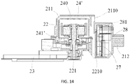
- FIG. 13 and FIG. 14 show a second embodiment of the hedge trimmer of the present disclosure.
- the structure of the hedge trimmer in the second embodiment is basically the same as that of the hedge trimmer 100 in the first embodiment, except for its power mechanism 20'.
- the power mechanism 20' will be described below.
- the power mechanism 20' is basically similar to the power mechanism 20 in the first embodiment, and the power mechanism 20' comprises a main housing 21, a motor 22, a power transmission assembly 23, an inner housing 24', a second fan 230, and a circuit board 27.
- the power mechanism 20' eliminates the first fan 26, and the connection type of each element of the power mechanism 20' is the same as that of the power mechanism 20 in the first embodiment.
- referral is made to the first embodiment.
- the structure of the inner housing 24' is slightly different, the structure of other elements is the same as that of the power mechanism 20 in the first embodiment.
- other elements follow the reference numerals in the first embodiment.
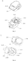
- the inner housing 24' in the second embodiment is similar to the inner housing 24 in the first embodiment, except that the top of the inner housing 24' is closed and a second opening 241' is arranged at the bottom. Preferably, multiple second openings 241' are arranged at the bottom of the inner housing 24'.
- the second opening 241' is opened on the side of the inner housing 24' directed away from the first air inlet 2110.
- the heat dissipation process of the power mechanism 20' of the hedge trimmer in the second embodiment can be summarized as below.
- the second fan 230 connected to the output shaft 221 of the motor 22 rotates, it generates a suction force and sucks in the external air from the first air inlet 2110 and the second air inlet 2120 into the top cover 211 and flows around the inner housing 24'. Then the air enters the motor room 240 through the second opening 241', and finally the air goes out through the bracket 212 of the main housing 21 and the power transmission assembly 23 to take away the heat in the motor room 240.
- the hedge trimmer in the second embodiment comprises a first air inlet 2110 at the top of the main housing 21, and at the same time, the top of the inner housing 24' is closed, and the second opening 241 is arranged at the bottom of the inner housing 24'.
- the hedge trimmer in the second embodiment has a good heat dissipation, improved waterproof and dustproof effect. It can work in rainy and humid areas without affecting the performance of the whole machine.
- the top cover 211 and the bracket 212 also form a receiving cavity 28 for accommodating the circuit board 27, which can be waterproof and dustproof to protect the circuit board 27.
- the receiving cavity 28 comprises a gap 281 for the circuit board 27 to dissipate the heat from electronic components.
- a first opening 241 is arranged at the top of the inner housing 24.
- the top of the inner housing 24' is closed, and the second opening 241' is arranged at the bottom of the inner housing 24'.
Landscapes
- Life Sciences & Earth Sciences (AREA)
- Biodiversity & Conservation Biology (AREA)
- Ecology (AREA)
- Forests & Forestry (AREA)
- Environmental Sciences (AREA)
- Engineering & Computer Science (AREA)
- Mechanical Engineering (AREA)
- Portable Power Tools In General (AREA)
Applications Claiming Priority (2)
| Application Number | Priority Date | Filing Date | Title |
|---|---|---|---|
| CN201910954170.6A CN110603979B (zh) | 2019-10-09 | 2019-10-09 | 修枝机 |
| CN201910953789.5A CN110603978B (zh) | 2019-10-09 | 2019-10-09 | 修枝机 |
Publications (3)
| Publication Number | Publication Date |
|---|---|
| EP3804502A1 true EP3804502A1 (fr) | 2021-04-14 |
| EP3804502B1 EP3804502B1 (fr) | 2024-02-21 |
| EP3804502C0 EP3804502C0 (fr) | 2024-02-21 |
Family
ID=72811764
Family Applications (1)
| Application Number | Title | Priority Date | Filing Date |
|---|---|---|---|
| EP20200900.7A Active EP3804502B1 (fr) | 2019-10-09 | 2020-10-08 | Outil électrique portatif |
Country Status (2)
| Country | Link |
|---|---|
| US (1) | US11548133B2 (fr) |
| EP (1) | EP3804502B1 (fr) |
Families Citing this family (4)
| Publication number | Priority date | Publication date | Assignee | Title |
|---|---|---|---|---|
| CN111567256A (zh) * | 2020-06-17 | 2020-08-25 | 格力博(江苏)股份有限公司 | 传动组件和园林工具 |
| JP1751095S (ja) * | 2023-03-13 | 2023-08-17 | ヘッジトリマー | |
| JP1751096S (ja) * | 2023-03-13 | 2023-08-17 | ヘッジトリマー | |
| DE102024122597A1 (de) | 2023-08-25 | 2025-02-27 | Makita Corporation | Arbeitsmaschine |
Citations (2)
| Publication number | Priority date | Publication date | Assignee | Title |
|---|---|---|---|---|
| WO2013062457A1 (fr) * | 2011-10-27 | 2013-05-02 | Husqvarna Ab | Outil électrique portatif alimenté par batterie |
| US20170071134A1 (en) * | 2015-09-15 | 2017-03-16 | Chervon (Hk) Limited | Hedge trimmer |
Family Cites Families (24)
| Publication number | Priority date | Publication date | Assignee | Title |
|---|---|---|---|---|
| US2660847A (en) * | 1950-06-24 | 1953-12-01 | Edwin F Britten | Grass trimmer and edger |
| US4242794A (en) * | 1979-02-27 | 1981-01-06 | Peterson Clayton R | Universal blower attachment unit |
| JP3205707B2 (ja) * | 1996-10-09 | 2001-09-04 | 本田技研工業株式会社 | 空冷エンジン |
| US6836036B2 (en) * | 2002-06-14 | 2004-12-28 | Dube Jean-Yves | Electric motor with modular stator ring and improved heat dissipation |
| TWM249458U (en) * | 2003-07-08 | 2004-11-11 | Yu-Shiang Huang | Structure of gear box for gardening device |
| WO2005075808A1 (fr) * | 2004-02-04 | 2005-08-18 | John Arthur Notaras | Systeme de filtre a air |
| JP5063970B2 (ja) * | 2006-10-02 | 2012-10-31 | 富士重工業株式会社 | 可搬式動力作業機 |
| JP2008302434A (ja) * | 2007-06-05 | 2008-12-18 | Hitachi Koki Co Ltd | 電動工具 |
| JP5047697B2 (ja) * | 2007-06-07 | 2012-10-10 | 株式会社マキタ | 電動工具 |
| DE102008041370A1 (de) * | 2008-08-20 | 2010-02-25 | Robert Bosch Gmbh | Elektrowerkzeug |
| DE102009012177A1 (de) * | 2009-02-27 | 2010-09-02 | Andreas Stihl Ag & Co. Kg | Akkubetriebenes, handgeführtes Elektrogerät |
| DE102010013756A1 (de) * | 2010-03-31 | 2011-10-06 | Andreas Stihl Ag & Co. Kg | Handgeführtes Arbeitsgerät |
| DE102012007405B4 (de) * | 2012-04-16 | 2017-02-09 | Andreas Stihl Ag & Co. Kg | Arbeitsgerät |
| US10369672B2 (en) * | 2012-10-19 | 2019-08-06 | Husqvarna Ab | Outdoor power device internal cooling system |
| US9467030B2 (en) * | 2013-03-15 | 2016-10-11 | Regal Beloit Australia Pty Ltd | Air-cooled electric machine and method of assembling the same |
| DE102013209061A1 (de) * | 2013-05-16 | 2014-11-20 | Robert Bosch Gmbh | Elektromotor mit verbesserter Kühlung |
| JP6460843B2 (ja) * | 2015-03-02 | 2019-01-30 | 株式会社やまびこ | 携帯型作業機 |
| US20160330914A1 (en) * | 2015-05-14 | 2016-11-17 | Jenn Feng New Energy Co., Ltd. | Hedge trimmer |
| DE102016106557A1 (de) * | 2016-04-11 | 2017-10-12 | Festool Gmbh | Hand-Werkzeugmaschine mit einem Antriebsmotor |
| DE102016106556A1 (de) * | 2016-04-11 | 2017-10-12 | Festool Gmbh | Hand-Werkzeugmaschine mit einem Absaugschlauch |
| CN109452026A (zh) * | 2017-09-06 | 2019-03-12 | 南京德朔实业有限公司 | 修枝机 |
| DE102018107808A1 (de) * | 2018-04-03 | 2019-10-10 | C. & E. Fein Gmbh | Handwerkzeugmaschine |
| SE1851031A1 (en) * | 2018-08-31 | 2020-03-01 | Husqvarna Ab | Power tool |
| JP7532200B2 (ja) * | 2020-10-16 | 2024-08-13 | 株式会社マキタ | オイルパルス工具 |
-
2020
- 2020-09-30 US US17/038,023 patent/US11548133B2/en active Active
- 2020-10-08 EP EP20200900.7A patent/EP3804502B1/fr active Active
Patent Citations (2)
| Publication number | Priority date | Publication date | Assignee | Title |
|---|---|---|---|---|
| WO2013062457A1 (fr) * | 2011-10-27 | 2013-05-02 | Husqvarna Ab | Outil électrique portatif alimenté par batterie |
| US20170071134A1 (en) * | 2015-09-15 | 2017-03-16 | Chervon (Hk) Limited | Hedge trimmer |
Also Published As
| Publication number | Publication date |
|---|---|
| US11548133B2 (en) | 2023-01-10 |
| US20210107129A1 (en) | 2021-04-15 |
| EP3804502B1 (fr) | 2024-02-21 |
| EP3804502C0 (fr) | 2024-02-21 |
Similar Documents
| Publication | Publication Date | Title |
|---|---|---|
| EP3804502B1 (fr) | Outil électrique portatif | |
| EP3753396B1 (fr) | Élagueuse | |
| US11648656B2 (en) | Electric handheld working machine | |
| EP3673722B1 (fr) | Outil de jardin et son ensemble d'alimentation | |
| CN110169272B (zh) | 修枝机 | |
| CN110810044A (zh) | 修枝机 | |
| CA2758673C (fr) | Structure de moteur a courant continu sans balais | |
| CN214314871U (zh) | 一种具有通风散热性能的无刷电机 | |
| CN215392873U (zh) | 交流无刷切割工具 | |
| EP3993235B1 (fr) | Tête de puissance et équipement d'alimentation extérieur l'utilisant | |
| CN110603978B (zh) | 修枝机 | |
| CN211353199U (zh) | 修枝机 | |
| US6239521B1 (en) | Motor cover arrangement | |
| CN211353198U (zh) | 修枝机 | |
| CN214430197U (zh) | 园林工具 | |
| CN107593087A (zh) | 一种割草机 | |
| CN211981665U (zh) | 动力头及电动工具 | |
| CN110603979B (zh) | 修枝机 | |
| CN211353196U (zh) | 修枝机 | |
| CN207354879U (zh) | 一种割草机 | |
| CN210247614U (zh) | 修枝机 | |
| WO2025051025A1 (fr) | Outil de jardin | |
| CN107615978A (zh) | 一种散热割草机 | |
| CN215421698U (zh) | 一种防淋雨和防进草风道的割草机 | |
| CN106508444B (zh) | 修枝机及其电机装置 |
Legal Events
| Date | Code | Title | Description |
|---|---|---|---|
| PUAI | Public reference made under article 153(3) epc to a published international application that has entered the european phase |
Free format text: ORIGINAL CODE: 0009012 |
|
| STAA | Information on the status of an ep patent application or granted ep patent |
Free format text: STATUS: THE APPLICATION HAS BEEN PUBLISHED |
|
| AK | Designated contracting states |
Kind code of ref document: A1 Designated state(s): AL AT BE BG CH CY CZ DE DK EE ES FI FR GB GR HR HU IE IS IT LI LT LU LV MC MK MT NL NO PL PT RO RS SE SI SK SM TR |
|
| AX | Request for extension of the european patent |
Extension state: BA ME |
|
| STAA | Information on the status of an ep patent application or granted ep patent |
Free format text: STATUS: REQUEST FOR EXAMINATION WAS MADE |
|
| 17P | Request for examination filed |
Effective date: 20210929 |
|
| RBV | Designated contracting states (corrected) |
Designated state(s): AL AT BE BG CH CY CZ DE DK EE ES FI FR GB GR HR HU IE IS IT LI LT LU LV MC MK MT NL NO PL PT RO RS SE SI SK SM TR |
|
| REG | Reference to a national code |
Ref country code: DE Ref legal event code: R079 Free format text: PREVIOUS MAIN CLASS: A01G0003053000 Ipc: B25F0005000000 Ref country code: DE Ref legal event code: R079 Ref document number: 602020025962 Country of ref document: DE Free format text: PREVIOUS MAIN CLASS: A01G0003053000 Ipc: B25F0005000000 |
|
| GRAP | Despatch of communication of intention to grant a patent |
Free format text: ORIGINAL CODE: EPIDOSNIGR1 |
|
| STAA | Information on the status of an ep patent application or granted ep patent |
Free format text: STATUS: GRANT OF PATENT IS INTENDED |
|
| RIC1 | Information provided on ipc code assigned before grant |
Ipc: B25F 5/02 20060101ALI20231109BHEP Ipc: A01G 3/08 20060101ALI20231109BHEP Ipc: A01G 3/053 20060101ALI20231109BHEP Ipc: B25F 5/00 20060101AFI20231109BHEP |
|
| GRAS | Grant fee paid |
Free format text: ORIGINAL CODE: EPIDOSNIGR3 |
|
| INTG | Intention to grant announced |
Effective date: 20231219 |
|
| GRAA | (expected) grant |
Free format text: ORIGINAL CODE: 0009210 |
|
| STAA | Information on the status of an ep patent application or granted ep patent |
Free format text: STATUS: THE PATENT HAS BEEN GRANTED |
|
| AK | Designated contracting states |
Kind code of ref document: B1 Designated state(s): AL AT BE BG CH CY CZ DE DK EE ES FI FR GB GR HR HU IE IS IT LI LT LU LV MC MK MT NL NO PL PT RO RS SE SI SK SM TR |
|
| REG | Reference to a national code |
Ref country code: GB Ref legal event code: FG4D |
|
| REG | Reference to a national code |
Ref country code: CH Ref legal event code: EP |
|
| REG | Reference to a national code |
Ref country code: DE Ref legal event code: R096 Ref document number: 602020025962 Country of ref document: DE |
|
| REG | Reference to a national code |
Ref country code: IE Ref legal event code: FG4D |
|
| U01 | Request for unitary effect filed |
Effective date: 20240221 |
|
| U07 | Unitary effect registered |
Designated state(s): AT BE BG DE DK EE FI FR IT LT LU LV MT NL PT SE SI Effective date: 20240229 |
|
| REG | Reference to a national code |
Ref country code: LT Ref legal event code: MG9D |
|
| PG25 | Lapsed in a contracting state [announced via postgrant information from national office to epo] |
Ref country code: IS Free format text: LAPSE BECAUSE OF FAILURE TO SUBMIT A TRANSLATION OF THE DESCRIPTION OR TO PAY THE FEE WITHIN THE PRESCRIBED TIME-LIMIT Effective date: 20240621 |
|
| PG25 | Lapsed in a contracting state [announced via postgrant information from national office to epo] |
Ref country code: GR Free format text: LAPSE BECAUSE OF FAILURE TO SUBMIT A TRANSLATION OF THE DESCRIPTION OR TO PAY THE FEE WITHIN THE PRESCRIBED TIME-LIMIT Effective date: 20240522 |
|
| PG25 | Lapsed in a contracting state [announced via postgrant information from national office to epo] |
Ref country code: HR Free format text: LAPSE BECAUSE OF FAILURE TO SUBMIT A TRANSLATION OF THE DESCRIPTION OR TO PAY THE FEE WITHIN THE PRESCRIBED TIME-LIMIT Effective date: 20240221 Ref country code: RS Free format text: LAPSE BECAUSE OF FAILURE TO SUBMIT A TRANSLATION OF THE DESCRIPTION OR TO PAY THE FEE WITHIN THE PRESCRIBED TIME-LIMIT Effective date: 20240521 |
|
| PG25 | Lapsed in a contracting state [announced via postgrant information from national office to epo] |
Ref country code: ES Free format text: LAPSE BECAUSE OF FAILURE TO SUBMIT A TRANSLATION OF THE DESCRIPTION OR TO PAY THE FEE WITHIN THE PRESCRIBED TIME-LIMIT Effective date: 20240221 |
|
| PG25 | Lapsed in a contracting state [announced via postgrant information from national office to epo] |
Ref country code: RS Free format text: LAPSE BECAUSE OF FAILURE TO SUBMIT A TRANSLATION OF THE DESCRIPTION OR TO PAY THE FEE WITHIN THE PRESCRIBED TIME-LIMIT Effective date: 20240521 Ref country code: NO Free format text: LAPSE BECAUSE OF FAILURE TO SUBMIT A TRANSLATION OF THE DESCRIPTION OR TO PAY THE FEE WITHIN THE PRESCRIBED TIME-LIMIT Effective date: 20240521 Ref country code: IS Free format text: LAPSE BECAUSE OF FAILURE TO SUBMIT A TRANSLATION OF THE DESCRIPTION OR TO PAY THE FEE WITHIN THE PRESCRIBED TIME-LIMIT Effective date: 20240621 Ref country code: HR Free format text: LAPSE BECAUSE OF FAILURE TO SUBMIT A TRANSLATION OF THE DESCRIPTION OR TO PAY THE FEE WITHIN THE PRESCRIBED TIME-LIMIT Effective date: 20240221 Ref country code: GR Free format text: LAPSE BECAUSE OF FAILURE TO SUBMIT A TRANSLATION OF THE DESCRIPTION OR TO PAY THE FEE WITHIN THE PRESCRIBED TIME-LIMIT Effective date: 20240522 Ref country code: ES Free format text: LAPSE BECAUSE OF FAILURE TO SUBMIT A TRANSLATION OF THE DESCRIPTION OR TO PAY THE FEE WITHIN THE PRESCRIBED TIME-LIMIT Effective date: 20240221 |
|
| PG25 | Lapsed in a contracting state [announced via postgrant information from national office to epo] |
Ref country code: PL Free format text: LAPSE BECAUSE OF FAILURE TO SUBMIT A TRANSLATION OF THE DESCRIPTION OR TO PAY THE FEE WITHIN THE PRESCRIBED TIME-LIMIT Effective date: 20240221 |
|
| PG25 | Lapsed in a contracting state [announced via postgrant information from national office to epo] |
Ref country code: PL Free format text: LAPSE BECAUSE OF FAILURE TO SUBMIT A TRANSLATION OF THE DESCRIPTION OR TO PAY THE FEE WITHIN THE PRESCRIBED TIME-LIMIT Effective date: 20240221 |
|
| PG25 | Lapsed in a contracting state [announced via postgrant information from national office to epo] |
Ref country code: SM Free format text: LAPSE BECAUSE OF FAILURE TO SUBMIT A TRANSLATION OF THE DESCRIPTION OR TO PAY THE FEE WITHIN THE PRESCRIBED TIME-LIMIT Effective date: 20240221 |
|
| PG25 | Lapsed in a contracting state [announced via postgrant information from national office to epo] |
Ref country code: CZ Free format text: LAPSE BECAUSE OF FAILURE TO SUBMIT A TRANSLATION OF THE DESCRIPTION OR TO PAY THE FEE WITHIN THE PRESCRIBED TIME-LIMIT Effective date: 20240221 |
|
| PG25 | Lapsed in a contracting state [announced via postgrant information from national office to epo] |
Ref country code: SK Free format text: LAPSE BECAUSE OF FAILURE TO SUBMIT A TRANSLATION OF THE DESCRIPTION OR TO PAY THE FEE WITHIN THE PRESCRIBED TIME-LIMIT Effective date: 20240221 |
|
| PG25 | Lapsed in a contracting state [announced via postgrant information from national office to epo] |
Ref country code: SM Free format text: LAPSE BECAUSE OF FAILURE TO SUBMIT A TRANSLATION OF THE DESCRIPTION OR TO PAY THE FEE WITHIN THE PRESCRIBED TIME-LIMIT Effective date: 20240221 Ref country code: SK Free format text: LAPSE BECAUSE OF FAILURE TO SUBMIT A TRANSLATION OF THE DESCRIPTION OR TO PAY THE FEE WITHIN THE PRESCRIBED TIME-LIMIT Effective date: 20240221 Ref country code: RO Free format text: LAPSE BECAUSE OF FAILURE TO SUBMIT A TRANSLATION OF THE DESCRIPTION OR TO PAY THE FEE WITHIN THE PRESCRIBED TIME-LIMIT Effective date: 20240221 Ref country code: CZ Free format text: LAPSE BECAUSE OF FAILURE TO SUBMIT A TRANSLATION OF THE DESCRIPTION OR TO PAY THE FEE WITHIN THE PRESCRIBED TIME-LIMIT Effective date: 20240221 |
|
| REG | Reference to a national code |
Ref country code: DE Ref legal event code: R097 Ref document number: 602020025962 Country of ref document: DE |
|
| U20 | Renewal fee for the european patent with unitary effect paid |
Year of fee payment: 5 Effective date: 20241028 |
|
| PLBE | No opposition filed within time limit |
Free format text: ORIGINAL CODE: 0009261 |
|
| STAA | Information on the status of an ep patent application or granted ep patent |
Free format text: STATUS: NO OPPOSITION FILED WITHIN TIME LIMIT |
|
| 26N | No opposition filed |
Effective date: 20241122 |
|
| REG | Reference to a national code |
Ref country code: CH Ref legal event code: PL |
|
| GBPC | Gb: european patent ceased through non-payment of renewal fee |
Effective date: 20241008 |
|
| PG25 | Lapsed in a contracting state [announced via postgrant information from national office to epo] |
Ref country code: MC Free format text: LAPSE BECAUSE OF FAILURE TO SUBMIT A TRANSLATION OF THE DESCRIPTION OR TO PAY THE FEE WITHIN THE PRESCRIBED TIME-LIMIT Effective date: 20240221 |
|
| PG25 | Lapsed in a contracting state [announced via postgrant information from national office to epo] |
Ref country code: GB Free format text: LAPSE BECAUSE OF NON-PAYMENT OF DUE FEES Effective date: 20241008 |
|
| PG25 | Lapsed in a contracting state [announced via postgrant information from national office to epo] |
Ref country code: CH Free format text: LAPSE BECAUSE OF NON-PAYMENT OF DUE FEES Effective date: 20241031 |
|
| PG25 | Lapsed in a contracting state [announced via postgrant information from national office to epo] |
Ref country code: IE Free format text: LAPSE BECAUSE OF NON-PAYMENT OF DUE FEES Effective date: 20241008 |
|
| U20 | Renewal fee for the european patent with unitary effect paid |
Year of fee payment: 6 Effective date: 20251027 |
|
| PG25 | Lapsed in a contracting state [announced via postgrant information from national office to epo] |
Ref country code: CY Free format text: LAPSE BECAUSE OF FAILURE TO SUBMIT A TRANSLATION OF THE DESCRIPTION OR TO PAY THE FEE WITHIN THE PRESCRIBED TIME-LIMIT; INVALID AB INITIO Effective date: 20201008 |
|
| PG25 | Lapsed in a contracting state [announced via postgrant information from national office to epo] |
Ref country code: HU Free format text: LAPSE BECAUSE OF FAILURE TO SUBMIT A TRANSLATION OF THE DESCRIPTION OR TO PAY THE FEE WITHIN THE PRESCRIBED TIME-LIMIT; INVALID AB INITIO Effective date: 20201008 |