EP3804652A1 - Detektionssystem, kathetervorrichtung und laserkauterisierungsvorrichtung - Google Patents
Detektionssystem, kathetervorrichtung und laserkauterisierungsvorrichtung Download PDFInfo
- Publication number
- EP3804652A1 EP3804652A1 EP19810570.2A EP19810570A EP3804652A1 EP 3804652 A1 EP3804652 A1 EP 3804652A1 EP 19810570 A EP19810570 A EP 19810570A EP 3804652 A1 EP3804652 A1 EP 3804652A1
- Authority
- EP
- European Patent Office
- Prior art keywords
- optical fiber
- reflected
- reflected beam
- bending
- threshold
- Prior art date
- Legal status (The legal status is an assumption and is not a legal conclusion. Google has not performed a legal analysis and makes no representation as to the accuracy of the status listed.)
- Granted
Links
Images



Classifications
-
- A—HUMAN NECESSITIES
- A61—MEDICAL OR VETERINARY SCIENCE; HYGIENE
- A61B—DIAGNOSIS; SURGERY; IDENTIFICATION
- A61B18/00—Surgical instruments, devices or methods for transferring non-mechanical forms of energy to or from the body
- A61B18/18—Surgical instruments, devices or methods for transferring non-mechanical forms of energy to or from the body by applying electromagnetic radiation, e.g. microwaves
- A61B18/20—Surgical instruments, devices or methods for transferring non-mechanical forms of energy to or from the body by applying electromagnetic radiation, e.g. microwaves using laser
- A61B18/22—Surgical instruments, devices or methods for transferring non-mechanical forms of energy to or from the body by applying electromagnetic radiation, e.g. microwaves using laser the beam being directed along or through a flexible conduit, e.g. an optical fibre; Couplings or hand-pieces therefor
- A61B18/24—Surgical instruments, devices or methods for transferring non-mechanical forms of energy to or from the body by applying electromagnetic radiation, e.g. microwaves using laser the beam being directed along or through a flexible conduit, e.g. an optical fibre; Couplings or hand-pieces therefor with a catheter
-
- A—HUMAN NECESSITIES
- A61—MEDICAL OR VETERINARY SCIENCE; HYGIENE
- A61B—DIAGNOSIS; SURGERY; IDENTIFICATION
- A61B1/00—Instruments for performing medical examinations of the interior of cavities or tubes of the body by visual or photographical inspection, e.g. endoscopes; Illuminating arrangements therefor
-
- A—HUMAN NECESSITIES
- A61—MEDICAL OR VETERINARY SCIENCE; HYGIENE
- A61B—DIAGNOSIS; SURGERY; IDENTIFICATION
- A61B18/00—Surgical instruments, devices or methods for transferring non-mechanical forms of energy to or from the body
- A61B18/18—Surgical instruments, devices or methods for transferring non-mechanical forms of energy to or from the body by applying electromagnetic radiation, e.g. microwaves
- A61B18/1815—Surgical instruments, devices or methods for transferring non-mechanical forms of energy to or from the body by applying electromagnetic radiation, e.g. microwaves using microwaves
-
- G—PHYSICS
- G01—MEASURING; TESTING
- G01M—TESTING STATIC OR DYNAMIC BALANCE OF MACHINES OR STRUCTURES; TESTING OF STRUCTURES OR APPARATUS, NOT OTHERWISE PROVIDED FOR
- G01M11/00—Testing of optical apparatus; Testing structures by optical methods not otherwise provided for
- G01M11/30—Testing of optical devices, constituted by fibre optics or optical waveguides
- G01M11/31—Testing of optical devices, constituted by fibre optics or optical waveguides with a light emitter and a light receiver being disposed at the same side of a fibre or waveguide end-face, e.g. reflectometers
-
- G—PHYSICS
- G02—OPTICS
- G02B—OPTICAL ELEMENTS, SYSTEMS OR APPARATUS
- G02B6/00—Light guides; Structural details of arrangements comprising light guides and other optical elements, e.g. couplings
- G02B6/24—Coupling light guides
- G02B6/42—Coupling light guides with opto-electronic elements
- G02B6/4201—Packages, e.g. shape, construction, internal or external details
- G02B6/4246—Bidirectionally operating package structures
-
- A—HUMAN NECESSITIES
- A61—MEDICAL OR VETERINARY SCIENCE; HYGIENE
- A61B—DIAGNOSIS; SURGERY; IDENTIFICATION
- A61B17/00—Surgical instruments, devices or methods
- A61B2017/00681—Aspects not otherwise provided for
- A61B2017/00725—Calibration or performance testing
-
- A—HUMAN NECESSITIES
- A61—MEDICAL OR VETERINARY SCIENCE; HYGIENE
- A61B—DIAGNOSIS; SURGERY; IDENTIFICATION
- A61B18/00—Surgical instruments, devices or methods for transferring non-mechanical forms of energy to or from the body
- A61B2018/00571—Surgical instruments, devices or methods for transferring non-mechanical forms of energy to or from the body for achieving a particular surgical effect
- A61B2018/00577—Ablation
-
- A—HUMAN NECESSITIES
- A61—MEDICAL OR VETERINARY SCIENCE; HYGIENE
- A61B—DIAGNOSIS; SURGERY; IDENTIFICATION
- A61B18/00—Surgical instruments, devices or methods for transferring non-mechanical forms of energy to or from the body
- A61B2018/00636—Sensing and controlling the application of energy
- A61B2018/00642—Sensing and controlling the application of energy with feedback, i.e. closed loop control
-
- A—HUMAN NECESSITIES
- A61—MEDICAL OR VETERINARY SCIENCE; HYGIENE
- A61B—DIAGNOSIS; SURGERY; IDENTIFICATION
- A61B18/00—Surgical instruments, devices or methods for transferring non-mechanical forms of energy to or from the body
- A61B2018/00636—Sensing and controlling the application of energy
- A61B2018/00666—Sensing and controlling the application of energy using a threshold value
- A61B2018/00678—Sensing and controlling the application of energy using a threshold value upper
-
- A—HUMAN NECESSITIES
- A61—MEDICAL OR VETERINARY SCIENCE; HYGIENE
- A61B—DIAGNOSIS; SURGERY; IDENTIFICATION
- A61B18/00—Surgical instruments, devices or methods for transferring non-mechanical forms of energy to or from the body
- A61B2018/00636—Sensing and controlling the application of energy
- A61B2018/00696—Controlled or regulated parameters
- A61B2018/00702—Power or energy
- A61B2018/00708—Power or energy switching the power on or off
-
- A—HUMAN NECESSITIES
- A61—MEDICAL OR VETERINARY SCIENCE; HYGIENE
- A61B—DIAGNOSIS; SURGERY; IDENTIFICATION
- A61B18/00—Surgical instruments, devices or methods for transferring non-mechanical forms of energy to or from the body
- A61B2018/00636—Sensing and controlling the application of energy
- A61B2018/00773—Sensed parameters
- A61B2018/00779—Power or energy
- A61B2018/00785—Reflected power
-
- A—HUMAN NECESSITIES
- A61—MEDICAL OR VETERINARY SCIENCE; HYGIENE
- A61B—DIAGNOSIS; SURGERY; IDENTIFICATION
- A61B18/00—Surgical instruments, devices or methods for transferring non-mechanical forms of energy to or from the body
- A61B2018/00636—Sensing and controlling the application of energy
- A61B2018/00773—Sensed parameters
- A61B2018/00791—Temperature
-
- A—HUMAN NECESSITIES
- A61—MEDICAL OR VETERINARY SCIENCE; HYGIENE
- A61B—DIAGNOSIS; SURGERY; IDENTIFICATION
- A61B18/00—Surgical instruments, devices or methods for transferring non-mechanical forms of energy to or from the body
- A61B2018/00636—Sensing and controlling the application of energy
- A61B2018/00773—Sensed parameters
- A61B2018/00827—Current
-
- A—HUMAN NECESSITIES
- A61—MEDICAL OR VETERINARY SCIENCE; HYGIENE
- A61B—DIAGNOSIS; SURGERY; IDENTIFICATION
- A61B18/00—Surgical instruments, devices or methods for transferring non-mechanical forms of energy to or from the body
- A61B2018/00636—Sensing and controlling the application of energy
- A61B2018/00898—Alarms or notifications created in response to an abnormal condition
-
- A—HUMAN NECESSITIES
- A61—MEDICAL OR VETERINARY SCIENCE; HYGIENE
- A61B—DIAGNOSIS; SURGERY; IDENTIFICATION
- A61B18/00—Surgical instruments, devices or methods for transferring non-mechanical forms of energy to or from the body
- A61B18/18—Surgical instruments, devices or methods for transferring non-mechanical forms of energy to or from the body by applying electromagnetic radiation, e.g. microwaves
- A61B18/1815—Surgical instruments, devices or methods for transferring non-mechanical forms of energy to or from the body by applying electromagnetic radiation, e.g. microwaves using microwaves
- A61B2018/1823—Generators therefor
-
- A—HUMAN NECESSITIES
- A61—MEDICAL OR VETERINARY SCIENCE; HYGIENE
- A61B—DIAGNOSIS; SURGERY; IDENTIFICATION
- A61B18/00—Surgical instruments, devices or methods for transferring non-mechanical forms of energy to or from the body
- A61B18/18—Surgical instruments, devices or methods for transferring non-mechanical forms of energy to or from the body by applying electromagnetic radiation, e.g. microwaves
- A61B18/20—Surgical instruments, devices or methods for transferring non-mechanical forms of energy to or from the body by applying electromagnetic radiation, e.g. microwaves using laser
- A61B18/22—Surgical instruments, devices or methods for transferring non-mechanical forms of energy to or from the body by applying electromagnetic radiation, e.g. microwaves using laser the beam being directed along or through a flexible conduit, e.g. an optical fibre; Couplings or hand-pieces therefor
- A61B2018/2247—Fibre breakage detection
-
- A—HUMAN NECESSITIES
- A61—MEDICAL OR VETERINARY SCIENCE; HYGIENE
- A61B—DIAGNOSIS; SURGERY; IDENTIFICATION
- A61B34/00—Computer-aided surgery; Manipulators or robots specially adapted for use in surgery
- A61B34/20—Surgical navigation systems; Devices for tracking or guiding surgical instruments, e.g. for frameless stereotaxis
- A61B2034/2046—Tracking techniques
- A61B2034/2061—Tracking techniques using shape-sensors, e.g. fiber shape sensors with Bragg gratings
Definitions
- the present invention relates to a detection system, a catheter device, and a laser ablation device. Background
- a detection system includes: at least one light source that outputs a plurality of test beams input to a proximal end portion of an optical fiber and having different wavelengths and providing different bending losses of the optical fiber; at least one reflector that reflects each of the test beams propagating through the optical fiber, near a distal end portion of the optical fiber; a plurality of light receiving units that receive a plurality of reflected beams each being a beam reflected by the at least one reflector, near the proximal end portion; and a determination unit that, based on information about the reflected beams at the plurality of light receiving units, compares the information about the reflected beams with reference set values.
- the detection system in a case where the received light intensity of the second reflected beam has rapidly decreased, information about an amount of bending is obtained from a state of decrease in the second reflected beam, when the received light intensity of the first reflected beam is larger than a first threshold.
- the detection system includes a plurality of the reflectors, at least one of which includes a fiber Bragg grating.
- At least one of the plurality of light receiving units is a photodiode.
- a catheter device includes: the detection system; the optical fiber to which the plurality of test beams are input from the proximal end portion, and in which the at least one reflector is provided near the distal end portion; and a catheter body into which at least a part of the optical fiber is inserted.
- a laser ablation device includes: the catheter device; and a laser beam source that outputs an ablation laser beam input to the proximal end portion of the optical fiber.
- FIG. 1 is a schematic diagram illustrating a schematic configuration of a laser ablation device according to an embodiment.
- the laser ablation device 1000 includes a laser beam source, which is not illustrated, an optical multiplexer/demultiplexer for an ablation laser, which is not illustrated, and a catheter device 100.
- the catheter device 100 includes a detection system 10 for optical fiber and a catheter portion 110.
- the catheter portion 110 is at least partially inserted into a patient's body.
- the catheter portion 110 includes a catheter body 120 that is formed of a flexible material such as resin, and an optical fiber 130 at least partially inserted into a lumen of the catheter body 120.
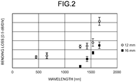
- FIG. 2 is a graph illustrating an example of a bending loss characteristic per turn of an optical fiber.
- the bending loss of an optical fiber is defined by an amount of increase in transmission loss per turn when the optical fiber is bent, for example, with a predetermined bend radius.
- one turn means a state in which the optical fiber is wound around once with a predetermined bend radius.
- white circles represent a bend radius of 6 mm (diameter of 12 mm)
- black squares represent a bend radius of 8 mm (diameter of 16 mm).
- an error bar represents a standard deviation calculated on the basis of 10 data points around a wavelength of a white circle or black square.
- the bending loss of an optical fiber generally increases with increasing wavelength. Therefore, making the wavelength of the second test beam TL2 longer than the wavelength of the first test beam TL1 can increase the bending loss in the second test beam TL2 relative to the bending loss in the first test beam TL1, in the optical fiber 130.
- the wavelength ⁇ 1 of the first test beam TL1 and the wavelength ⁇ 2 of the second test beam TL2 can be set in a 1300 nm band and the wavelength ⁇ 2 can be set in a 1500 nm band. It can be seen from FIG. 2 that the bending loss is smaller in the 1300 nm band than in the 1500 nm band (note that the band has a bandwidth of 100 nm, for example, the 1500 nm band has a bandwidth of 1500 to 1600 nm).
- the optical multiplexer/demultiplexer 3a multiplexes the first test beam TL1 and the second test beam TL2 at a predetermined ratio, for example, a ratio of 1:1 and outputs the multiplexed beam to the optical multiplexer/demultiplexer for an ablation laser via an optical fiber represented by a solid line.
- the optical multiplexer/demultiplexer for an ablation laser multiplexes the input first test beam TL1 and second test beam TL2 with the laser beam AL and outputs the multiplexed beam to the optical multiplexer/demultiplexer 3b via the optical fiber represented by the solid line.
- the optical multiplexer/demultiplexer 3b outputs the input first test beam TL1, second test beam TL2, and laser beam AL to the optical fiber 130 via an optical fiber represented by a solid line. Therefore, the first test beam TL1, the second test beam TL2, and the laser beam AL are input to the proximal end portion 131 of the optical fiber 130 and propagate through the optical fiber 130.
- the FBG 7 is provided near the distal end portion 132 of the optical fiber 130 and is fusion-spliced, for example, to the distal end portion 132 of the optical fiber 130.
- the FBG 7 reflects the first test beam TL1 and the second test beam TL2 propagating through the optical fiber 130 and transmits the laser beam AL. Therefore, the laser beam AL is output from the distal end portion 132 of the optical fiber 130 (a distal end portion of the catheter portion 110).
- a first reflected beam RL1 that is a reflected beam from the first test beam TL1 and a second reflected beam RL2 that is a reflected beam from the second test beam TL2 propagate through the optical fiber 130 in the opposite direction to the first test beam TL1 and the second test beam TL2 and are output from the proximal end portion 131 to the optical multiplexer/demultiplexer 3b.
- the optical multiplexer/demultiplexer 3b outputs the input first reflected beam RL1 and second reflected beam RL2 to the optical multiplexer/demultiplexer 3c.
- the bandpass filter 4a is designed to selectively transmit light having a wavelength of the second reflected beam RL2 and hardly transmit light having a wavelength of the first reflected beam RL1.
- the bandpass filters 4a and 4b may be configured to also block light having a wavelength of the laser beam AL.
- the laser beam AL has high power, there is a possibility that light that is obtained by Fresnel reflection of the laser beam AL due to air at an end portion of the FBG 7 reaches the PDs 2a and 2b.
- the bandpass filters 4a and 4b may be used to remove this reflection.
- the PD 2a receives the first reflected beam RL1 having passed through the bandpass filter 4a and outputs a current signal according to the received light intensity of the first reflected beam RL1.
- the PD 2b receives the second reflected beam RL2 having passed through the bandpass filter 4b and outputs a current signal according to the received light intensity of the second reflected beam RL2.
- the bandpass filters 4a and 4b may not be required depending on configuration.
- the bandpass filters 4a and 4b are not required in principle due to high extinction ratio and efficient demultiplexing.
- the PD 2a employs a Si photodiode and the PD 2b employs an InGaAs photodiode.
- Si has extremely poor sensitivity at a wavelength of 1100 nm band or more, and therefore, for example, if the wavelength ⁇ 1 of the first test beam TL1 is set in a 800 nm band and the wavelength ⁇ 2 of the second test beam TL2 is set in the 1500 nm band, the bandpass filter 4a is not required for the PD 2a, which is an Si photodiode that receives the first reflected beam RL1 in the 800 nm band.
- optical multiplexers/demultiplexers 3a, 3b, and 3c are preferably constituted by a 50:50 TAP coupler, an asymmetric TAP coupler, a WDM coupler, or a combination thereof.
- the control unit 5 has a function of a determination unit.
- the control unit 5 includes a calculation unit and a storage unit.
- the calculation unit performs various calculation processes for achieving controls executed by the control unit 5 and the functions of the control unit and includes, for example, a central processing unit (CPU), a field-programmable gate array (FPGA), or both of the CPU and the FPGA.
- the storage unit includes a portion constituted by, for example, a read only memory (ROM), and the portion stores various programs and data used by the calculation unit to perform the calculation processes.
- the storage unit includes a portion constituted by, for example, a random access memory (RAM), and the portion is used such as for a work space when the calculation unit performs a calculation process or for storing results of the calculation processes of the calculation unit.
- RAM random access memory
- the temperature (body temperature) or pressure (blood pressure) at a portion to which the catheter portion 110 is inserted can be monitored.
- control unit 5 includes an output unit, and the output unit outputs, on the basis of the results of the various calculation processes, driving current to the LDs 1a and 1b, a laser beam output stop signal for stopping output of the laser beam AL from the laser beam source, and an instruction signal to the display unit 6.
- the display unit 6 is a portion that displays characters and symbols for notifying an operator of the laser ablation device 1000 of various information, in response to an instruction signal from the control unit 5 and includes, for example, a liquid crystal display.
- FIG. 3 is a flowchart of a first control example. This control process is performed in a state where the control unit 5 supplies the driving current to the LDs 1a and 1b, and the first test beam TL1 and the second test beam TL2 are output.
- Step S105 the control unit 5 outputs an instruction signal to the display unit 6 to display characters, symbols or the like for notifying of the breakage of the optical fiber 130. Then, the control ends.
- Step S106 the control unit 5 determines whether the intensity of the second reflected beam RL2 is not more than a predetermined bending threshold. If the intensity of the second reflected beam RL2 is not more than the predetermined bending threshold (Step S106: Yes), the control proceeds to Step S107.
- the bending threshold is a reference set value used when the catheter portion 110 is inserted into an unexpected wrong portion. Note that reference set values are stored in the storage unit of the control unit 5 in the form of an array or the like, as a table or function expressions. This configuration enables the control unit 5 to calculate the amount of bending of the optical fiber 130 on the basis of an input value, and the magnitude of the amount of bending can be determined by comparison with a reference set value relating to the amount of bending.
- the control unit 5 determines that the optical fiber 130 is bent with an abnormal amount of bending that is equal to or larger than a predictable amount of bending.
- the amount of bending is an amount indicating the degree of bending of the optical fiber 130.
- the amount of bending can be expressed as, for example, the amount of an increase in transmission loss (bending loss) caused by bending of the optical fiber 130 and can be expressed as the total bending loss occurring over the entire length of the optical fiber 130.
- the bending threshold is a value corresponding to a light intensity indicated when, for example, a bending loss of 1 dB is given.
- the first threshold as the reference set value used for the determination is set to a value that is small to the extent to determine the breakage of the optical fiber 130 on the basis of a result of a preliminary experiment or the like and is stored in the storage unit of the control unit 5.
- the output of the laser beam AL is stopped.
- the effect of preventing the laser beam AL from being unintentionally output from the broken portion of the optical fiber 130 can be obtained.
- the effect can be obtained that the operator of the laser ablation device 1000 can be notified of the breakage of the optical fiber 130.
- the catheter portion 110 is inserted into a human body or a living body, the airway, esophagus, or blood vessel have sharply bending portions in common. Therefore, normally predictable bending losses of the optical fiber 130 in a passage route in the catheter portion 110 can be almost derived. From this point, when a bending loss that is larger than a normally predictable bending loss of the optical fiber 130 in a passage route is generated, there is a possibility that the catheter portion 110 has been inserted into a wrong portion into which no insertion of the catheter portion 110 is expected.
- the received light intensity of the first reflected beam RL1 is larger than the first threshold and the intensity of the second reflected beam RL2 is not more than the bending threshold, it can be detected whether the catheter portion 110 is inserted in a wrong direction with sharp bending of the optical fiber 130 that exceeds the predictable amount of bending or whether any portion of the inserted portion is caught and sharply bent. Therefore, an effect can be obtained that when it is determined that the catheter portion is bent with the abnormal amount of bending, the operator can be notified of this and thus, the safety in use of the catheter portion 110 can be improved.
- the bending threshold that is a reference set value for the determination is set to a value corresponding to an abnormal amount of bending of the optical fiber 130 that the operator is to be notified of, on the basis of a result of a preliminary experiment or the like, and the bending threshold is stored in the storage unit of the control unit 5.
- Step S201 the control unit 5 detects the intensity of the first reflected beam RL1 and the intensity of the second reflected beam RL2, as in Step S101 of the first control example. Subsequently, in Step S202, the control unit 5 determines whether the intensity of the first reflected beam RL1 is not more than the first threshold, as in Step S102 of the first control example. If the intensity of the first reflected beam RL1 is not more than the first threshold (Step S202: Yes), the control proceeds to Step S203. At this time, the control unit 5 determines that the optical fiber 130 is broken.
- Step S203 the control unit 5 determines whether the intensity of the second reflected beam RL2 is not more than a third threshold. If the intensity of the second reflected beam RL2 is not more than the third threshold (Step S203: Yes), the control proceeds to Step S204. At this time, the control unit 5 maintains the determination that the optical fiber 130 is broken.
- the received light intensity of the first reflected beam RL1 that is less sensitive to the bending of the optical fiber 130 is not more than the first threshold but the received light intensity of the second reflected beam RL2 that is sensitive to the bending of the optical fiber 130 is larger than the third threshold, it can be considered that such a state does not correspond to the state where the optical fiber 130 is bent or broken but has a situation where some kind of system error has occurred. Therefore, in the second control example, it is determined that a system error has occurred, and the operator can be notified of the system error.
- the third threshold that is a reference set value for the determination is set to the same value as the second threshold, for example and is stored in the storage unit of the control unit 5.
- Step S301 the control unit 5 detects the intensity of the first reflected beam RL1 and the intensity of the second reflected beam RL2. Subsequently, in Step S302, the control unit 5 determines whether the intensity of the second reflected beam RL2 is not more than the second threshold. If the intensity of the second reflected beam RL2 is not more than the second threshold (Step S302: Yes), the control proceeds to Step S303. At this time, the control unit 5 determines that the optical fiber 130 is bent with an amount of bending not less than a predetermined amount of bending.
- Step S303 the control unit 5 determines whether the intensity of the first reflected beam RL1 is not more than the first threshold. If the intensity of the first reflected beam RL1 is not more than the first threshold (Step S303: Yes), the control proceeds to Step S304. At this time, the control unit 5 changes the determination that the optical fiber 130 is bent with an amount of bending not less than a predetermined amount of bending to a determination that the optical fiber 130 is broken.
- Step S306 the control unit 5 causes the display unit 6 to display characters, symbols or the like for notifying of the breakage of the optical fiber 130. Then, the control ends.
- Step S307 the control unit 5 determines whether the intensity of the first reflected beam RL1 is not more than the first threshold. If the intensity of the first reflected beam RL1 is not more than the first threshold (Step S307: Yes), the control proceeds to Step S308. At this time, the control unit 5 determines that a system error has occurred in the detection system 10, the catheter device 100, or the laser ablation device 1000.
- the third control example various effects similar to those of the first control example can be obtained. Furthermore, in the third control example, when the received light intensity of the second reflected beam RL2 is larger than the second threshold and the received light intensity of the first reflected beam RL1 is not more than the first threshold, it is determined that a system error has occurred in the detection system 10, the catheter device 100, or the laser ablation device 1000. As in the second control example, when the received light intensity of the first reflected beam RL1 is not more than the first threshold but the received light intensity of the second reflected beam RL2 is larger than the second threshold, it can be considered that such a state has a situation where some kind of system error has occurred. Therefore, in the third control example, it is determined that a system error has occurred, and the operator can be notified of the system error.
- Step S404 the control unit 5 determines whether the laser beam AL is being output. If the laser beam AL is being output (Step S404: Yes), the control proceeds to Step S405. In Step S405, the control unit 5 outputs the laser beam output stop signal to the laser beam source. If the laser beam AL is not output (Step S404: No) or after the end of Step S405, the control proceeds to Step S406.
Landscapes
- Physics & Mathematics (AREA)
- Health & Medical Sciences (AREA)
- Life Sciences & Earth Sciences (AREA)
- Surgery (AREA)
- Optics & Photonics (AREA)
- Biomedical Technology (AREA)
- Animal Behavior & Ethology (AREA)
- Nuclear Medicine, Radiotherapy & Molecular Imaging (AREA)
- Veterinary Medicine (AREA)
- Public Health (AREA)
- General Health & Medical Sciences (AREA)
- Engineering & Computer Science (AREA)
- Molecular Biology (AREA)
- Heart & Thoracic Surgery (AREA)
- Medical Informatics (AREA)
- General Physics & Mathematics (AREA)
- Electromagnetism (AREA)
- Otolaryngology (AREA)
- Chemical & Material Sciences (AREA)
- Analytical Chemistry (AREA)
- Biophysics (AREA)
- Pathology (AREA)
- Radiology & Medical Imaging (AREA)
- Laser Surgery Devices (AREA)
- Testing Of Optical Devices Or Fibers (AREA)
- Lasers (AREA)
- Endoscopes (AREA)
Applications Claiming Priority (2)
| Application Number | Priority Date | Filing Date | Title |
|---|---|---|---|
| JP2018106290 | 2018-06-01 | ||
| PCT/JP2019/021076 WO2019230713A1 (ja) | 2018-06-01 | 2019-05-28 | 検知システム、カテーテル装置、およびレーザ焼灼装置 |
Publications (3)
| Publication Number | Publication Date |
|---|---|
| EP3804652A1 true EP3804652A1 (de) | 2021-04-14 |
| EP3804652A4 EP3804652A4 (de) | 2022-03-02 |
| EP3804652B1 EP3804652B1 (de) | 2025-01-29 |
Family
ID=68698784
Family Applications (1)
| Application Number | Title | Priority Date | Filing Date |
|---|---|---|---|
| EP19810570.2A Active EP3804652B1 (de) | 2018-06-01 | 2019-05-28 | Kathetervorrichtung zur laserablation mit einem faserzustandserkennungssystem |
Country Status (5)
| Country | Link |
|---|---|
| US (1) | US12426949B2 (de) |
| EP (1) | EP3804652B1 (de) |
| JP (1) | JP7335875B2 (de) |
| CN (1) | CN112203609B (de) |
| WO (1) | WO2019230713A1 (de) |
Cited By (1)
| Publication number | Priority date | Publication date | Assignee | Title |
|---|---|---|---|---|
| EP3949887A4 (de) * | 2019-03-29 | 2022-12-14 | Furukawa Electric Co., Ltd. | Glasfaserzustandserkennungssystem |
Families Citing this family (37)
| Publication number | Priority date | Publication date | Assignee | Title |
|---|---|---|---|---|
| WO2018187708A1 (en) | 2017-04-07 | 2018-10-11 | Bard Access Systems, Inc. | Optical fiber-based medical device tracking and monitoring system |
| WO2020186074A1 (en) * | 2019-03-14 | 2020-09-17 | Worcester Polytechnic Institute | Flexible articulating surgical probe |
| WO2021030092A1 (en) | 2019-08-12 | 2021-02-18 | Bard Access Systems, Inc. | Shape-sensing systems and methods for medical devices |
| US11850338B2 (en) | 2019-11-25 | 2023-12-26 | Bard Access Systems, Inc. | Optical tip-tracking systems and methods thereof |
| CN112826480B (zh) | 2019-11-25 | 2025-04-18 | 巴德阿克塞斯系统股份有限公司 | 具有滤波器的形状感测系统及其方法 |
| WO2021167085A1 (ja) * | 2020-02-20 | 2021-08-26 | 古河電気工業株式会社 | 光ファイバの接続状態判断システム及び光ファイバの接続状態判断方法 |
| CN113318324A (zh) | 2020-02-28 | 2021-08-31 | 巴德阿克塞斯系统股份有限公司 | 具有光学形状感测能力的导管 |
| CN215340440U (zh) | 2020-02-28 | 2021-12-28 | 巴德阿克塞斯系统股份有限公司 | 电学和光学连接系统及光学连接系统 |
| WO2021178578A1 (en) | 2020-03-03 | 2021-09-10 | Bard Access Systems, Inc. | System and method for optic shape sensing and electrical signal conduction |
| WO2021202589A1 (en) | 2020-03-30 | 2021-10-07 | Bard Access Systems, Inc. | Optical and electrical diagnostic systems and methods thereof |
| CN113842536B (zh) | 2020-06-26 | 2026-03-17 | 巴德阿克塞斯系统股份有限公司 | 错位检测系统 |
| WO2022005870A1 (en) | 2020-06-29 | 2022-01-06 | Bard Access Systems, Inc. | Automatic dimensional frame reference for fiber optic |
| WO2022011287A1 (en) * | 2020-07-10 | 2022-01-13 | Bard Access Systems, Inc. | Continuous fiber optic functionality monitoring and self-diagnostic reporting system |
| CN216675721U (zh) | 2020-08-03 | 2022-06-07 | 巴德阿克塞斯系统股份有限公司 | 布拉格光栅光纤波动感测与监测系统 |
| US12064569B2 (en) | 2020-09-25 | 2024-08-20 | Bard Access Systems, Inc. | Fiber optics oximetry system for detection and confirmation |
| CN216985791U (zh) | 2020-10-13 | 2022-07-19 | 巴德阿克塞斯系统股份有限公司 | 用于光纤连接器的消毒罩 |
| CN216455277U (zh) | 2020-10-13 | 2022-05-10 | 巴德阿克塞斯系统股份有限公司 | 用于将医疗器械插入患者体内的医疗器械系统 |
| CN216558785U (zh) | 2020-11-18 | 2022-05-17 | 巴德阿克塞斯系统股份有限公司 | 光纤管心针保持器 |
| US12220219B2 (en) | 2020-11-24 | 2025-02-11 | Bard Access Systems, Inc. | Steerable fiber optic shape sensing enabled elongated medical instrument |
| CN217040287U (zh) | 2021-01-06 | 2022-07-26 | 巴德阿克塞斯系统股份有限公司 | 用于将医疗器械插入患者体内的医疗器械系统 |
| CN114788733A (zh) | 2021-01-26 | 2022-07-26 | 巴德阿克塞斯系统股份有限公司 | 与端口放置相关联的光纤形状传感系统 |
| US12480838B2 (en) * | 2021-02-18 | 2025-11-25 | Sony Group Corporation | Measuring device, measuring method, and electronic device |
| US12490937B2 (en) | 2021-05-18 | 2025-12-09 | Bard Access Systems, Inc. | Anatomical oscillation and fluctuation sensing and confirmation system |
| FR3126318B1 (fr) * | 2021-08-27 | 2025-04-04 | Commissariat Energie Atomique | Dispositif implantable d'illumination cérébrale à solution de surveillance de sonde optique |
| WO2023043947A1 (en) | 2021-09-16 | 2023-03-23 | Bard Access Systems, Inc. | Swappable high mating cycle fiber connection interface |
| EP4418994A1 (de) | 2021-10-25 | 2024-08-28 | Bard Access Systems, Inc. | Referenzebene zur platzierung einer medizinischen vorrichtung |
| US12318149B2 (en) | 2022-03-08 | 2025-06-03 | Bard Access Systems, Inc. | Medical shape sensing devices and systems |
| US12426956B2 (en) | 2022-03-16 | 2025-09-30 | Bard Access Systems, Inc. | Medical system and method for monitoring medical device insertion and illumination patterns |
| US12089815B2 (en) | 2022-03-17 | 2024-09-17 | Bard Access Systems, Inc. | Fiber optic medical systems and devices with atraumatic tip |
| US12605116B2 (en) | 2022-04-11 | 2026-04-21 | Bard Access Systems, Inc. | Fiber optic medical systems and devices with electrical tip |
| US12575893B2 (en) | 2022-06-24 | 2026-03-17 | Bard Access Systems, Inc. | Shape sensing fiber optic tip protection systems and devices |
| US12343117B2 (en) | 2022-06-28 | 2025-07-01 | Bard Access Systems, Inc. | Fiber optic medical systems and methods for identifying blood vessels |
| US12349984B2 (en) | 2022-06-29 | 2025-07-08 | Bard Access Systems, Inc. | System, method, and apparatus for improved confirm of an anatomical position of a medical instrument |
| US12564340B2 (en) | 2022-07-12 | 2026-03-03 | Bard Access Systems, Inc. | Eccentric single-core fiber-optic enabled medical device |
| WO2025248699A1 (ja) * | 2024-05-30 | 2025-12-04 | Ntt株式会社 | 制御システム |
| JP7844067B1 (ja) * | 2025-07-07 | 2026-04-13 | 株式会社オプトゲート | エアロゾル検出システム |
| CN121015311B (zh) * | 2025-10-29 | 2026-03-03 | 湖南省华芯医疗器械有限公司 | 激光设备的控制方法、装置、介质以及内窥镜 |
Family Cites Families (26)
| Publication number | Priority date | Publication date | Assignee | Title |
|---|---|---|---|---|
| JPS6398507U (de) * | 1986-12-17 | 1988-06-25 | ||
| US4883054A (en) * | 1987-12-09 | 1989-11-28 | Fuller Research Corporation | Optical fiber break detector |
| JPH03111039A (ja) * | 1989-09-26 | 1991-05-10 | Olympus Optical Co Ltd | レーザ治療装置 |
| JP4454747B2 (ja) | 1999-12-21 | 2010-04-21 | オリンパス株式会社 | 内視鏡挿入形状検出装置 |
| JP2002291764A (ja) * | 2001-03-29 | 2002-10-08 | Nidek Co Ltd | レーザ治療装置 |
| US6819815B1 (en) * | 2001-12-12 | 2004-11-16 | Calient Networks | Method and apparatus for indirect adjustment of optical switch reflectors |
| JP2004251779A (ja) * | 2003-02-20 | 2004-09-09 | Fuji Photo Optical Co Ltd | 長尺可撓部材の三次元形状検出装置 |
| JP4714570B2 (ja) * | 2005-11-24 | 2011-06-29 | Hoya株式会社 | 内視鏡形状検出プローブ |
| US7336862B1 (en) * | 2007-03-22 | 2008-02-26 | General Electric Company | Fiber optic sensor for detecting multiple parameters in a harsh environment |
| US8050523B2 (en) * | 2007-04-20 | 2011-11-01 | Koninklijke Philips Electronics N.V. | Optical fiber shape sensing systems |
| US8773650B2 (en) * | 2009-09-18 | 2014-07-08 | Intuitive Surgical Operations, Inc. | Optical position and/or shape sensing |
| CN106788694A (zh) * | 2010-05-27 | 2017-05-31 | 爱斯福公司 | 多采集otdr方法及装置 |
| US9183714B2 (en) * | 2012-10-17 | 2015-11-10 | Douglas E. Piper, Sr. | Entrance security system |
| US9134197B2 (en) * | 2013-01-15 | 2015-09-15 | Exfo Inc. | Bi-directional multi-pulsewidth optical time-domain reflectometer |
| US12514456B2 (en) * | 2013-01-31 | 2026-01-06 | Eximo Medical Ltd. | System and methods for lesion characterization in blood vessels |
| US9719883B2 (en) * | 2013-06-10 | 2017-08-01 | General Photonics Corporation | Devices and methods for characterization of distributed fiber bend and stress |
| JP2015181643A (ja) | 2014-03-24 | 2015-10-22 | オリンパス株式会社 | 湾曲形状推定システム、管状挿入システム、及び、湾曲部材の湾曲形状推定方法 |
| JP6278848B2 (ja) * | 2014-06-26 | 2018-02-14 | オリンパス株式会社 | 形状推定装置、それを備えた内視鏡システム及び形状推定のためのプログラム |
| US9726538B2 (en) * | 2014-10-14 | 2017-08-08 | Optilab, Llc | Apparatus and method for sensing parameters using Fiber Bragg Grating (FBG) sensor and comparator |
| JP6398004B2 (ja) * | 2015-05-29 | 2018-09-26 | オリンパス株式会社 | 曲率センサ及びそれを搭載した内視鏡装置 |
| WO2017060956A1 (ja) * | 2015-10-05 | 2017-04-13 | オリンパス株式会社 | 形状演算装置 |
| JP6691602B2 (ja) * | 2016-01-07 | 2020-04-28 | セント・ジュード・メディカル・インターナショナル・ホールディング・エスエーアールエルSt. Jude Medical International Holding S.a,r.l. | 光学的感知のためのマルチ・コア・ファイバを有する医療デバイス |
| JP6493265B2 (ja) * | 2016-03-24 | 2019-04-03 | オムロン株式会社 | 光学計測装置 |
| CN112689482B (zh) * | 2018-09-10 | 2024-06-25 | 古河电气工业株式会社 | 光探针、医疗用激光探针以及烧灼装置 |
| JP7203658B2 (ja) * | 2019-03-27 | 2023-01-13 | 古河電気工業株式会社 | レーザ装置 |
| CN113631114B (zh) * | 2019-03-29 | 2024-11-05 | 古河电气工业株式会社 | 光纤的弯曲状态检测系统 |
-
2019
- 2019-05-28 CN CN201980035534.9A patent/CN112203609B/zh active Active
- 2019-05-28 JP JP2020522207A patent/JP7335875B2/ja active Active
- 2019-05-28 EP EP19810570.2A patent/EP3804652B1/de active Active
- 2019-05-28 WO PCT/JP2019/021076 patent/WO2019230713A1/ja not_active Ceased
-
2020
- 2020-11-17 US US17/099,938 patent/US12426949B2/en active Active
Cited By (1)
| Publication number | Priority date | Publication date | Assignee | Title |
|---|---|---|---|---|
| EP3949887A4 (de) * | 2019-03-29 | 2022-12-14 | Furukawa Electric Co., Ltd. | Glasfaserzustandserkennungssystem |
Also Published As
| Publication number | Publication date |
|---|---|
| EP3804652A4 (de) | 2022-03-02 |
| CN112203609B (zh) | 2024-06-28 |
| CN112203609A (zh) | 2021-01-08 |
| US20210068899A1 (en) | 2021-03-11 |
| JP7335875B2 (ja) | 2023-08-30 |
| JPWO2019230713A1 (ja) | 2021-07-26 |
| US12426949B2 (en) | 2025-09-30 |
| EP3804652B1 (de) | 2025-01-29 |
| WO2019230713A1 (ja) | 2019-12-05 |
Similar Documents
| Publication | Publication Date | Title |
|---|---|---|
| EP3804652A1 (de) | Detektionssystem, kathetervorrichtung und laserkauterisierungsvorrichtung | |
| US11553964B2 (en) | Optical probe, medical laser probe, and cauterization device | |
| EP2050411B1 (de) | Lichtbestrahlungsgerät | |
| US20140241385A1 (en) | Low-mode high power fiber combiner | |
| EP3032217A1 (de) | Optischer sensor, optisches sensorsystem und endoskop | |
| US11291376B2 (en) | Fiber bragg grating multi-point pressure sensing guidewire with birefringent component | |
| EP3949887B1 (de) | Glasfaserzustandserkennungssystem | |
| EP4456811B1 (de) | Faseroptische einwegvorrichtung | |
| KR20140035944A (ko) | 광 도파로를 위한 커플링 장치 | |
| EP4108198B1 (de) | System zur bestimmung des zustands einer faserverbindung und verfahren zur bestimmung des zustands einer faserverbindung | |
| US20170370697A1 (en) | Bending detecting system, light guide body, tubular apparatus, light detecting apparatus, light detecting method, and optical bending measuring apparatus | |
| JP5180704B2 (ja) | 内視鏡用ライトガイド | |
| JP2019174256A (ja) | 光ファイバ折れ検知システムおよび光ファイバ折れ検知方法 | |
| TWI637570B (zh) | 光纖雷射裝置 | |
| WO2023126337A1 (en) | Disposable fiber-optic device |
Legal Events
| Date | Code | Title | Description |
|---|---|---|---|
| STAA | Information on the status of an ep patent application or granted ep patent |
Free format text: STATUS: THE INTERNATIONAL PUBLICATION HAS BEEN MADE |
|
| PUAI | Public reference made under article 153(3) epc to a published international application that has entered the european phase |
Free format text: ORIGINAL CODE: 0009012 |
|
| STAA | Information on the status of an ep patent application or granted ep patent |
Free format text: STATUS: REQUEST FOR EXAMINATION WAS MADE |
|
| 17P | Request for examination filed |
Effective date: 20201118 |
|
| AK | Designated contracting states |
Kind code of ref document: A1 Designated state(s): AL AT BE BG CH CY CZ DE DK EE ES FI FR GB GR HR HU IE IS IT LI LT LU LV MC MK MT NL NO PL PT RO RS SE SI SK SM TR |
|
| AX | Request for extension of the european patent |
Extension state: BA ME |
|
| DAV | Request for validation of the european patent (deleted) | ||
| DAX | Request for extension of the european patent (deleted) | ||
| A4 | Supplementary search report drawn up and despatched |
Effective date: 20220131 |
|
| RIC1 | Information provided on ipc code assigned before grant |
Ipc: A61B 18/18 20060101ALI20220125BHEP Ipc: G02B 6/42 20060101ALI20220125BHEP Ipc: G01M 11/00 20060101ALI20220125BHEP Ipc: A61B 1/00 20060101ALI20220125BHEP Ipc: A61B 18/22 20060101AFI20220125BHEP |
|
| STAA | Information on the status of an ep patent application or granted ep patent |
Free format text: STATUS: EXAMINATION IS IN PROGRESS |
|
| 17Q | First examination report despatched |
Effective date: 20240216 |
|
| GRAP | Despatch of communication of intention to grant a patent |
Free format text: ORIGINAL CODE: EPIDOSNIGR1 |
|
| STAA | Information on the status of an ep patent application or granted ep patent |
Free format text: STATUS: GRANT OF PATENT IS INTENDED |
|
| INTG | Intention to grant announced |
Effective date: 20240903 |
|
| GRAS | Grant fee paid |
Free format text: ORIGINAL CODE: EPIDOSNIGR3 |
|
| GRAA | (expected) grant |
Free format text: ORIGINAL CODE: 0009210 |
|
| STAA | Information on the status of an ep patent application or granted ep patent |
Free format text: STATUS: THE PATENT HAS BEEN GRANTED |
|
| AK | Designated contracting states |
Kind code of ref document: B1 Designated state(s): AL AT BE BG CH CY CZ DE DK EE ES FI FR GB GR HR HU IE IS IT LI LT LU LV MC MK MT NL NO PL PT RO RS SE SI SK SM TR |
|
| P01 | Opt-out of the competence of the unified patent court (upc) registered |
Free format text: CASE NUMBER: APP_67273/2024 Effective date: 20241219 |
|
| REG | Reference to a national code |
Ref country code: GB Ref legal event code: FG4D |
|
| REG | Reference to a national code |
Ref country code: CH Ref legal event code: EP |
|
| REG | Reference to a national code |
Ref country code: DE Ref legal event code: R096 Ref document number: 602019065444 Country of ref document: DE |
|
| REG | Reference to a national code |
Ref country code: IE Ref legal event code: FG4D |
|
| REG | Reference to a national code |
Ref country code: NL Ref legal event code: MP Effective date: 20250129 |
|
| PG25 | Lapsed in a contracting state [announced via postgrant information from national office to epo] |
Ref country code: NL Free format text: LAPSE BECAUSE OF FAILURE TO SUBMIT A TRANSLATION OF THE DESCRIPTION OR TO PAY THE FEE WITHIN THE PRESCRIBED TIME-LIMIT Effective date: 20250129 |
|
| PG25 | Lapsed in a contracting state [announced via postgrant information from national office to epo] |
Ref country code: RS Free format text: LAPSE BECAUSE OF FAILURE TO SUBMIT A TRANSLATION OF THE DESCRIPTION OR TO PAY THE FEE WITHIN THE PRESCRIBED TIME-LIMIT Effective date: 20250429 |
|
| PG25 | Lapsed in a contracting state [announced via postgrant information from national office to epo] |
Ref country code: FI Free format text: LAPSE BECAUSE OF FAILURE TO SUBMIT A TRANSLATION OF THE DESCRIPTION OR TO PAY THE FEE WITHIN THE PRESCRIBED TIME-LIMIT Effective date: 20250129 |
|
| PG25 | Lapsed in a contracting state [announced via postgrant information from national office to epo] |
Ref country code: PL Free format text: LAPSE BECAUSE OF FAILURE TO SUBMIT A TRANSLATION OF THE DESCRIPTION OR TO PAY THE FEE WITHIN THE PRESCRIBED TIME-LIMIT Effective date: 20250129 |
|
| PGFP | Annual fee paid to national office [announced via postgrant information from national office to epo] |
Ref country code: DE Payment date: 20250521 Year of fee payment: 7 |
|
| PG25 | Lapsed in a contracting state [announced via postgrant information from national office to epo] |
Ref country code: ES Free format text: LAPSE BECAUSE OF FAILURE TO SUBMIT A TRANSLATION OF THE DESCRIPTION OR TO PAY THE FEE WITHIN THE PRESCRIBED TIME-LIMIT Effective date: 20250129 |
|
| REG | Reference to a national code |
Ref country code: LT Ref legal event code: MG9D |
|
| PG25 | Lapsed in a contracting state [announced via postgrant information from national office to epo] |
Ref country code: IS Free format text: LAPSE BECAUSE OF FAILURE TO SUBMIT A TRANSLATION OF THE DESCRIPTION OR TO PAY THE FEE WITHIN THE PRESCRIBED TIME-LIMIT Effective date: 20250529 Ref country code: NO Free format text: LAPSE BECAUSE OF FAILURE TO SUBMIT A TRANSLATION OF THE DESCRIPTION OR TO PAY THE FEE WITHIN THE PRESCRIBED TIME-LIMIT Effective date: 20250429 |
|
| REG | Reference to a national code |
Ref country code: AT Ref legal event code: MK05 Ref document number: 1762694 Country of ref document: AT Kind code of ref document: T Effective date: 20250129 |
|
| PG25 | Lapsed in a contracting state [announced via postgrant information from national office to epo] |
Ref country code: HR Free format text: LAPSE BECAUSE OF FAILURE TO SUBMIT A TRANSLATION OF THE DESCRIPTION OR TO PAY THE FEE WITHIN THE PRESCRIBED TIME-LIMIT Effective date: 20250129 |
|
| PG25 | Lapsed in a contracting state [announced via postgrant information from national office to epo] |
Ref country code: LV Free format text: LAPSE BECAUSE OF FAILURE TO SUBMIT A TRANSLATION OF THE DESCRIPTION OR TO PAY THE FEE WITHIN THE PRESCRIBED TIME-LIMIT Effective date: 20250129 Ref country code: PT Free format text: LAPSE BECAUSE OF FAILURE TO SUBMIT A TRANSLATION OF THE DESCRIPTION OR TO PAY THE FEE WITHIN THE PRESCRIBED TIME-LIMIT Effective date: 20250529 |
|
| PG25 | Lapsed in a contracting state [announced via postgrant information from national office to epo] |
Ref country code: GR Free format text: LAPSE BECAUSE OF FAILURE TO SUBMIT A TRANSLATION OF THE DESCRIPTION OR TO PAY THE FEE WITHIN THE PRESCRIBED TIME-LIMIT Effective date: 20250430 Ref country code: BG Free format text: LAPSE BECAUSE OF FAILURE TO SUBMIT A TRANSLATION OF THE DESCRIPTION OR TO PAY THE FEE WITHIN THE PRESCRIBED TIME-LIMIT Effective date: 20250129 |
|
| PG25 | Lapsed in a contracting state [announced via postgrant information from national office to epo] |
Ref country code: AT Free format text: LAPSE BECAUSE OF FAILURE TO SUBMIT A TRANSLATION OF THE DESCRIPTION OR TO PAY THE FEE WITHIN THE PRESCRIBED TIME-LIMIT Effective date: 20250129 |
|
| PG25 | Lapsed in a contracting state [announced via postgrant information from national office to epo] |
Ref country code: SE Free format text: LAPSE BECAUSE OF FAILURE TO SUBMIT A TRANSLATION OF THE DESCRIPTION OR TO PAY THE FEE WITHIN THE PRESCRIBED TIME-LIMIT Effective date: 20250129 |
|
| PG25 | Lapsed in a contracting state [announced via postgrant information from national office to epo] |
Ref country code: SM Free format text: LAPSE BECAUSE OF FAILURE TO SUBMIT A TRANSLATION OF THE DESCRIPTION OR TO PAY THE FEE WITHIN THE PRESCRIBED TIME-LIMIT Effective date: 20250129 |
|
| PG25 | Lapsed in a contracting state [announced via postgrant information from national office to epo] |
Ref country code: DK Free format text: LAPSE BECAUSE OF FAILURE TO SUBMIT A TRANSLATION OF THE DESCRIPTION OR TO PAY THE FEE WITHIN THE PRESCRIBED TIME-LIMIT Effective date: 20250129 |
|
| PG25 | Lapsed in a contracting state [announced via postgrant information from national office to epo] |
Ref country code: IT Free format text: LAPSE BECAUSE OF FAILURE TO SUBMIT A TRANSLATION OF THE DESCRIPTION OR TO PAY THE FEE WITHIN THE PRESCRIBED TIME-LIMIT Effective date: 20250129 |
|
| PG25 | Lapsed in a contracting state [announced via postgrant information from national office to epo] |
Ref country code: CZ Free format text: LAPSE BECAUSE OF FAILURE TO SUBMIT A TRANSLATION OF THE DESCRIPTION OR TO PAY THE FEE WITHIN THE PRESCRIBED TIME-LIMIT Effective date: 20250129 Ref country code: EE Free format text: LAPSE BECAUSE OF FAILURE TO SUBMIT A TRANSLATION OF THE DESCRIPTION OR TO PAY THE FEE WITHIN THE PRESCRIBED TIME-LIMIT Effective date: 20250129 |
|
| PG25 | Lapsed in a contracting state [announced via postgrant information from national office to epo] |
Ref country code: RO Free format text: LAPSE BECAUSE OF FAILURE TO SUBMIT A TRANSLATION OF THE DESCRIPTION OR TO PAY THE FEE WITHIN THE PRESCRIBED TIME-LIMIT Effective date: 20250129 |
|
| PG25 | Lapsed in a contracting state [announced via postgrant information from national office to epo] |
Ref country code: SK Free format text: LAPSE BECAUSE OF FAILURE TO SUBMIT A TRANSLATION OF THE DESCRIPTION OR TO PAY THE FEE WITHIN THE PRESCRIBED TIME-LIMIT Effective date: 20250129 |
|
| REG | Reference to a national code |
Ref country code: DE Ref legal event code: R097 Ref document number: 602019065444 Country of ref document: DE |
|
| PLBE | No opposition filed within time limit |
Free format text: ORIGINAL CODE: 0009261 |
|
| STAA | Information on the status of an ep patent application or granted ep patent |
Free format text: STATUS: NO OPPOSITION FILED WITHIN TIME LIMIT |
|
| REG | Reference to a national code |
Ref country code: CH Ref legal event code: L10 Free format text: ST27 STATUS EVENT CODE: U-0-0-L10-L00 (AS PROVIDED BY THE NATIONAL OFFICE) Effective date: 20251210 |
|
| REG | Reference to a national code |
Ref country code: CH Ref legal event code: H13 Free format text: ST27 STATUS EVENT CODE: U-0-0-H10-H13 (AS PROVIDED BY THE NATIONAL OFFICE) Effective date: 20251223 |
|
| 26N | No opposition filed |
Effective date: 20251030 |
|
| PG25 | Lapsed in a contracting state [announced via postgrant information from national office to epo] |
Ref country code: LU Free format text: LAPSE BECAUSE OF NON-PAYMENT OF DUE FEES Effective date: 20250528 |
|
| PG25 | Lapsed in a contracting state [announced via postgrant information from national office to epo] |
Ref country code: CH Free format text: LAPSE BECAUSE OF NON-PAYMENT OF DUE FEES Effective date: 20250531 |
|
| GBPC | Gb: european patent ceased through non-payment of renewal fee |
Effective date: 20250528 |
|
| REG | Reference to a national code |
Ref country code: BE Ref legal event code: MM Effective date: 20250531 |
|
| PG25 | Lapsed in a contracting state [announced via postgrant information from national office to epo] |
Ref country code: MC Free format text: LAPSE BECAUSE OF FAILURE TO SUBMIT A TRANSLATION OF THE DESCRIPTION OR TO PAY THE FEE WITHIN THE PRESCRIBED TIME-LIMIT Effective date: 20250129 |
|
| PG25 | Lapsed in a contracting state [announced via postgrant information from national office to epo] |
Ref country code: GB Free format text: LAPSE BECAUSE OF NON-PAYMENT OF DUE FEES Effective date: 20250528 |
|
| PG25 | Lapsed in a contracting state [announced via postgrant information from national office to epo] |
Ref country code: IE Free format text: LAPSE BECAUSE OF NON-PAYMENT OF DUE FEES Effective date: 20250528 |
|
| PG25 | Lapsed in a contracting state [announced via postgrant information from national office to epo] |
Ref country code: BE Free format text: LAPSE BECAUSE OF NON-PAYMENT OF DUE FEES Effective date: 20250531 |
|
| PG25 | Lapsed in a contracting state [announced via postgrant information from national office to epo] |
Ref country code: FR Free format text: LAPSE BECAUSE OF NON-PAYMENT OF DUE FEES Effective date: 20250531 |