EP3804875B1 - Verfahren zur herstellung einer gepressten komponente - Google Patents
Verfahren zur herstellung einer gepressten komponente Download PDFInfo
- Publication number
- EP3804875B1 EP3804875B1 EP19806798.5A EP19806798A EP3804875B1 EP 3804875 B1 EP3804875 B1 EP 3804875B1 EP 19806798 A EP19806798 A EP 19806798A EP 3804875 B1 EP3804875 B1 EP 3804875B1
- Authority
- EP
- European Patent Office
- Prior art keywords
- ridgeline
- lower die
- pad
- bending
- vertical wall
- Prior art date
- Legal status (The legal status is an assumption and is not a legal conclusion. Google has not performed a legal analysis and makes no representation as to the accuracy of the status listed.)
- Active
Links
Images


Classifications
-
- B—PERFORMING OPERATIONS; TRANSPORTING
- B21—MECHANICAL METAL-WORKING WITHOUT ESSENTIALLY REMOVING MATERIAL; PUNCHING METAL
- B21D—WORKING OR PROCESSING OF SHEET METAL OR METAL TUBES, RODS OR PROFILES WITHOUT ESSENTIALLY REMOVING MATERIAL; PUNCHING METAL
- B21D22/00—Shaping without cutting, by stamping, spinning, or deep-drawing
- B21D22/20—Deep-drawing
- B21D22/22—Deep-drawing with devices for holding the edge of the blanks
-
- B—PERFORMING OPERATIONS; TRANSPORTING
- B21—MECHANICAL METAL-WORKING WITHOUT ESSENTIALLY REMOVING MATERIAL; PUNCHING METAL
- B21D—WORKING OR PROCESSING OF SHEET METAL OR METAL TUBES, RODS OR PROFILES WITHOUT ESSENTIALLY REMOVING MATERIAL; PUNCHING METAL
- B21D22/00—Shaping without cutting, by stamping, spinning, or deep-drawing
- B21D22/20—Deep-drawing
- B21D22/26—Deep-drawing for making peculiarly, e.g. irregularly, shaped articles
-
- B—PERFORMING OPERATIONS; TRANSPORTING
- B21—MECHANICAL METAL-WORKING WITHOUT ESSENTIALLY REMOVING MATERIAL; PUNCHING METAL
- B21D—WORKING OR PROCESSING OF SHEET METAL OR METAL TUBES, RODS OR PROFILES WITHOUT ESSENTIALLY REMOVING MATERIAL; PUNCHING METAL
- B21D22/00—Shaping without cutting, by stamping, spinning, or deep-drawing
- B21D22/02—Stamping using rigid devices or tools
-
- B—PERFORMING OPERATIONS; TRANSPORTING
- B21—MECHANICAL METAL-WORKING WITHOUT ESSENTIALLY REMOVING MATERIAL; PUNCHING METAL
- B21D—WORKING OR PROCESSING OF SHEET METAL OR METAL TUBES, RODS OR PROFILES WITHOUT ESSENTIALLY REMOVING MATERIAL; PUNCHING METAL
- B21D19/00—Flanging or other edge treatment, e.g. of tubes
- B21D19/08—Flanging or other edge treatment, e.g. of tubes by single or successive action of pressing tools, e.g. vice jaws
-
- B—PERFORMING OPERATIONS; TRANSPORTING
- B21—MECHANICAL METAL-WORKING WITHOUT ESSENTIALLY REMOVING MATERIAL; PUNCHING METAL
- B21D—WORKING OR PROCESSING OF SHEET METAL OR METAL TUBES, RODS OR PROFILES WITHOUT ESSENTIALLY REMOVING MATERIAL; PUNCHING METAL
- B21D24/00—Special deep-drawing arrangements in, or in connection with, presses
-
- B—PERFORMING OPERATIONS; TRANSPORTING
- B21—MECHANICAL METAL-WORKING WITHOUT ESSENTIALLY REMOVING MATERIAL; PUNCHING METAL
- B21D—WORKING OR PROCESSING OF SHEET METAL OR METAL TUBES, RODS OR PROFILES WITHOUT ESSENTIALLY REMOVING MATERIAL; PUNCHING METAL
- B21D37/00—Tools as parts of machines covered by this subclass
- B21D37/10—Die sets; Pillar guides
-
- B—PERFORMING OPERATIONS; TRANSPORTING
- B21—MECHANICAL METAL-WORKING WITHOUT ESSENTIALLY REMOVING MATERIAL; PUNCHING METAL
- B21D—WORKING OR PROCESSING OF SHEET METAL OR METAL TUBES, RODS OR PROFILES WITHOUT ESSENTIALLY REMOVING MATERIAL; PUNCHING METAL
- B21D53/00—Making other particular articles
- B21D53/88—Making other particular articles other parts for vehicles, e.g. cowlings, mudguards
Definitions
- Manufacturing methods disclosed in PTL 1 and PTL 2 are examples of a technology for avoiding such stretch flange cracking.
- an L-shaped component is manufactured by pressurizing a blank material by a pad in a state where an end portion of a portion corresponding to a lower side of the L shape of the blank material is in the same plane as the top sheet portion of a product, and, in this state, performing bending by an upper die.
- the method disclosed in PTL 2 performs bending of a vertical wall portion and a flange portion after forming a linear bead extending along a transverse end portion and steps on a blank material.
- PTL 4 discloses a method for press-forming an L-shaped component from a blank metal sheet.
- the blank material at the position of the top sheet portion in the curved portion moves in an in-plane direction under the pad during bending, thereby improving the stretch flange cracking in the curved portion.
- the moving amount and the moving rate of a portion sandwiched by the die (lower die) and the pad during the forming are governed by a frictional force between the die (the pad or the punch) and the blank material.
- the moving amount fluctuates depending on a change in the state of a die surface caused by wear of the die or a change in the state of an oil coat on a material surface.
- the present invention has been made in view of the problem as described above. It is an object of the present invention to provide a technology capable of simply and more stably suppressing stretch flange cracking in a curved portion.
- the present inventors found that the above problem can be solved by performing bending of a vertical wall portion and a flange portion by bending-based forming using a pad in such a manner as to move a metal sheet portion sandwiched by a lower die and the pad to the vertical wall portion side while applying a fold line (an out-of-plane deformation having a mountain-shaped cross section) on the metal sheet portion by the sandwiching.
- a simple change in die structure enables a component including a curved portion recessed toward a top sheet portion in a top view, such as an L-shaped component or a T-shaped component, to be manufactured with further reduced sporadic stretch flange cracking.
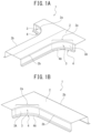
- a method for manufacturing a press-formed component 1 of the present embodiment is a method for manufacturing the press-formed component 1, which manufactures the press-formed component 1 by press forming a metal sheet (referred to also as blank material) into a previously set press-formed shape.
- the set press-formed shape is a component shape (see FIG. 1 ) including a top sheet portion 2 including a curved outer peripheral edge portion 2a curved in such a manner that a part of an outer peripheral edge is recessed inward, a vertical wall portion 3A continuous with the curved outer peripheral edge portion 2a of the top sheet portion 2, and a flange portion 4A continuous with the vertical wall portion 3A and bent toward the top sheet portion 2.
- the method for manufacturing the press-formed component 1 of the present embodiment is a technology that is suitable when the metal sheet is a high tensile strength steel sheet having a tensile strength of 590 MPa or more, preferably 780 MPa or more.
- the method for manufacturing the press-formed component 1 of the present embodiment manufactures the press-formed component 1 by bending-based press forming.
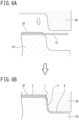
- a press forming die for use in the press forming of the present embodiment includes an upper die 40 (bending die), a lower die 20 (punch), and a pad 30 (see FIGS. 6 and 7 ).
- a sandwiching region P that is a region including at least a part of a region corresponding to the top sheet portion 2 in the metal sheet is sandwiched by the lower die 20 and the pad 30. Then, by moving the upper die 40 relatively with respect to the lower die 20 in a pressing direction, the vertical wall portion 3 and the flange portion 4 are bent into a desired component shape while moving the material of the sandwiching region P sandwiched by the lower die 20 and the pad 30 to the vertical wall portion 3 side.
- a difference (hereinafter referred to also as fold angle ⁇ ) between the surface inclinations on both sides of the ridgeline 20a is set to from 1 degree to less than 90 degrees (see FIG. 7 ).
- the fold angle ⁇ is preferably from 3 degrees to 15 degrees, and more preferably from 3 degrees to 10 degrees.
- a bend radius R1 at the position of the ridgeline 20a is set to, for example, from 0.1 mm to 30 mm (see FIG. 7 ).
- the bend radius is a radius on a side of less than 180 degrees.
- the lower die 20 and the pad 30 press at least the region (sandwiching region P) including the top sheet portion 2 of the curved portion that is a region where material movement occurs during bending.
- the ridgelines 20a and 30a provided on the lower die 20 and the pad 30 give a bend that is an out-of-plane deformation to the sandwiched metal sheet portion at the positions of the ridgelines 20a and 30a.
- the material of the metal sheet 10 portion sandwiched by the pad 30 and the lower die 20 moves to the vertical wall portion 3A side in the region of the vertical wall portion 3A and the flange portion 4A continuous with the curved outer peripheral edge portion 2a, as illustrated in FIG. 7 .
- the lower die 20 is provided with the ridgeline 20a.
- the material of the metal sheet 10 portion sandwiched by the pad 30 and the lower die 20 passes through the position of the ridgeline 20a, the material is bent while undergoing out-of-plane bending and unbending at the position of the ridgeline 20a, with the bend position continuously moving along with the movement of the material.
- bending and unbending resistances can be continuously generated in the material in addition to a frictional resistance between the die and the material, which can stabilize the amount of material movement on the top sheet surface during bending.
- the bending and unbending resistances are larger than the frictional resistance, and are less susceptible to fluctuations in mass production. Therefore, in the present embodiment, fluctuations in material movement in mass production can be reduced, so that sporadic stretch flange cracking can be more effectively suppressed.
- the lower die 20 is formed with a surface having a mountain-shaped cross section with the ridgeline 20a at the top.
- a bead shape having a semicircular or trapezoidal cross section is formed instead of forming the ridgeline 20a, the number of times of bending and unbending increases as compared to when the ridgeline 20a is formed, which easily causes surface defects. Then, the surface defects left in a product may be problematic.
- use of a bead shape requires large pad force as compared to the ridgeline 20a. Due to that, when a bead shape is used, it is insufficient to secure the pad force due to the structure of the die depending on the shape of the pad (particularly when the pad is small in size). In that case, the material is insufficiently pressed by the pad during forming, and the amount of material movement on the top sheet surface during the forming may be unstable, so that control may be difficult.
- the bend radius R1 of the bent ridgeline 20a is 0.1 mm or less, die galling is highly likely to occur at the time of passage through the ridgeline positions, and if it is 30 mm or more, the bending and unbending resistances are likely to be insufficient. Therefore, the bend radius R1 is preferably from 0.1 mm to 30 mm. In addition, considering the combination with the bend angle, the bend radius R1 is more preferably from 1 mm to 20 mm.
- the bent ridgeline 20a (fold angle ⁇ and bend radius R1) in accordance with the product shape, the surface state of a material such as plating, the shape of the metal sheet 10, and the like.
- Appropriate conditions can be obtained from computer simulation by FEM analysis.
- the ridgelines 20a and 30a are set on the entire length of the region where material movement occurs.
- increasing the number of the ridgelines 20a can reduce the fold angle ⁇ of each ridgeline 20a.
- the positions of the ridgelines 20a and 30a are set inside a final product in which bending has been completed by moving the upper die 40 to the bottom dead center, sliding marks may occur in the region where the material has passed through the ridgelines 20a and 30a during the forming, which can affect appearance quality. Furthermore, since fold lines formed by the ridgelines 20a and 30a are left in the product, the shape of the product can be restricted.
- the positions of the ridgelines 20a and 30a are preferably set such that the position corresponding to the top sheet portion 2 in the metal sheet 10 is at a position that has moved to the vertical wall portion 3 side rather than the positions of the ridgelines 20a and 30a when the forming of the vertical wall portion 3 and the flange portion 4 by the relative movement of the upper die 40 is complete.
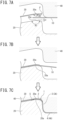
- FIG. 9 illustrates a relationship between the lower die 20 and the component 1 at the time of completion of the bending.
- the present embodiment enables L- or T-shaped components that could cause stretch flange cracking to be manufactured stably at low cost even in mass production.
- FIG. 7 exemplifies the case where the ridgeline 20a is set so as to protrude upward, the ridgeline 20a may be set so as to protrude downward, as illustrated in FIG. 10 .
- the one or more ridgelines provided in the sandwiching region P are set at the position such that the position of the top sheet portion 2 is located on the vertical wall portion 3 side rather than the positions of all the ridgelines.
- the second embodiment is different from the first embodiment in that the position of each ridgeline is set such that at least a part of at least one ridgeline of all the ridgelines provided in the sandwiching region P overlaps with the top sheet portion 2 in the state where the bending is complete.
- a method for manufacturing the press-formed component 1 of the present embodiment is a method for manufacturing the press-formed component 1, which manufactures the press-formed component 1 by press forming a metal sheet (referred to also as blank material) into a previously set press formed shape.
- the set press formed shape is a component shape (see FIG. 1 ) including a top sheet portion 2 including a curved outer peripheral edge portion 2a curved in such a manner that a part of an outer peripheral edge is recessed inward, a vertical wall portion 3A continuous with the curved outer peripheral edge portion 2a of the top sheet portion 2, and a flange portion 4A continuous with the vertical wall portion 3A and bent toward the top sheet portion 2.
- the method for manufacturing the press-formed component 1 of the present embodiment is a technology that is suitable when the metal sheet is a high tensile strength steel sheet having a tensile strength of 590 MPa or more, preferably 780 MPa or more.
- the press-formed component 1 that is the subject of the present embodiment is the same as that of the first embodiment, such as, for example, a T-shaped component or an L-shaped component, as illustrated in FIG. 1 .
- the method for manufacturing the press-formed component 1 of the present embodiment also manufactures the press-formed component 1 by bending-based press forming.
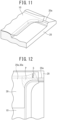
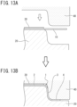
- a press forming die for use in the press forming of the present embodiment includes an upper die 40 (bending die), a lower die 20 (punch), and a pad 30 (see FIGS. 13 and 14 ).
- the ridgeline 20a is arranged on the side where the distance from the curved outer peripheral edge portion 2a to the end portion of the metal sheet 10 is small.
- a difference (hereinafter referred to also as fold angle ⁇ ) between the surface inclinations on both sides of the ridgeline 20a is set to from 1 degree to less than 90 degrees (see FIG. 14 ).
- the fold angle ⁇ is preferably from 3 degrees to 15 degrees, and more preferably from 3 degrees to 10 degrees.
- a bend radius R1 at the position of the ridgeline 20a is set to, for example, from 0.1 mm to 30 mm (see FIG. 14 ).
- the bend radius is a radius on a side of less than 180 degrees.
- the ridgeline 20a does not necessarily have to linearly extend, and may be formed so as to slightly curve.
- a structural analysis such as CAD analysis may be performed to estimate the moving direction S of the material, and an extending direction of the ridgeline 20a may be set so as to be orthogonal to the estimated moving direction S of the material.
- the two or more ridgelines 20a are formed so as to be aligned in the moving direction S of the material.
- Directions of protruding sides of the two or more ridgelines 20a are preferably set in the same direction in a vertical direction (see FIG. 15 ).
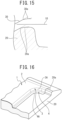
- each ridgeline 20a in the present embodiment, the position of each ridgeline 20a is set such that, in the state where the forming of the vertical wall portion 3 and the flange portion 4 by the relative movement of the upper die 40 is complete, at least a part of at least one ridgeline 20a of all the ridgelines 20a overlaps with the top sheet portion 2.
- at least a part of the ridgeline 20a is set so as to overlap with the top sheet portion 2 in the state where the bending is complete (see FIG. 16 ).
- the ridgeline 30a of the pad 30 side is formed at a position vertically facing the ridgeline 20a formed on the surface of the lower die 20, and the sandwiching surface of the pad 30 has different surface inclinations on both sides of the ridgeline 30a.
- a difference (fold angle ⁇ ) between the surface inclinations on both sides of the ridgeline 30a on the sandwiching surface of the pad 30 and a bend radius R2 are set to be equal to the difference ⁇ between the inclinations on the lower die 20 and the bend radius R1 (see FIG. 14 ).
- the bend radius R2 does not have to be equal to the bend radius R1, but is preferably equal to or less than the bend radius R1.
- a pressure of the pad pressure (sandwiching pressure by the lower die 20 and the pad 30) is set to a pressure at which no wrinkles occur on the top sheet portion 2 of the curved portion during bending (for example, a pressure at which a gap between the pad 30 and the punch does not become equal to or larger than a thickness of the blank material until a forming bottom dead center). Then, the blank material is pressed in a state where the material can move in the curved portion during the above bending.
- a step of providing a partial shape to the top sheet surface or the like may be provided.
- restriking to a final product or trimming of the outer periphery may be performed.
- provision of a shape such as a seating face for spot welding, a trimming and piercing step, and a restriking step can be added as pre- and post-steps.
Landscapes
- Engineering & Computer Science (AREA)
- Mechanical Engineering (AREA)
- Shaping Metal By Deep-Drawing, Or The Like (AREA)
- Bending Of Plates, Rods, And Pipes (AREA)
Claims (4)
- Verfahren zur Herstellung einer pressgeformten Komponente, das die pressgeformte Komponente durch Pressformen eines Metallblechs (10) zu einer Komponentenform herstellt, die einen oberen Blechabschnitt (2), der einen gekrümmten äußeren Umfangskantenabschnitt (2a) aufweist, der derart gekrümmt ist, dass ein Teil einer äußeren Umfangskante nach innen vertieft ist, einen vertikalen Wandabschnitt (3, 3A), der durchgehend mit dem gekrümmten äußeren Umfangskantenabschnitt des oberen Blechabschnitts ist, und einen Flanschabschnitt (4, 4A), der durchgehend mit dem vertikalen Wandabschnitt ist und in Richtung der Seite des oberen Blechabschnitts gebogen ist, beinhaltet, wobei das Verfahren Folgendes umfasst:in einem Zustand, in dem eine untere Matrize (20) und eine Auflage (30) einen Einbettungsbereich (P), der ein Bereich ist, der mindestens einen Teil eines Bereichs beinhaltet, der dem oberen Blechabschnitt (2) in dem Metallblech (10) entspricht, einklemmen, Bewegen einer oberen Matrize (40) relativ zu der unteren Matrize (20) in einer Pressrichtung, um ein Biegen des vertikalen Wandabschnitts (3, 3A) und des Flanschabschnitts (4, 4A) durchzuführen, während mindestens ein Teil eines Materials des Einbettungsbereichs (P), der durch die untere Matrize (20) und die Auflage (30) eingeklemmt ist, zu der Seite des vertikalen Wandabschnitts bewegt wird,wobei während des Biegens, wenn das Material bewegt wird, außerhalb der Ebene liegende Biege- und Streckverformungen durchgehend auf den Metallblechbereich, der durch die untere Matrize (20) und die Auflage (30) eingeklemmt ist, an einer Position eines Biegeabschnitts aufgebracht werden, der sich in einer Richtung erstreckt, die eine Bewegungsrichtung (S) des Materials schneidet, um die Bewegung des Materials zu steuern, wobei eine Oberfläche der unteren Matrize (20), die den Einbettungsbereich (P) einklemmt, als der Biegeabschnitt mit einer oder mehreren Gratlinien (20a) versehen ist, die sich in der Richtung erstrecken, die die Bewegungsrichtung (S) des Materials schneidet, wobei die Oberfläche der unteren Matrize auf beiden Seiten jeder der Gratlinien (20a) unterschiedliche Oberflächenneigungen aufweist und wobei jede Gratlinie derart an einer Position festgelegt ist, dass in einem Zustand, in dem das Biegen abgeschlossen ist, eine Position des oberen Blechabschnitts auf einer Seite des vertikalen Wandabschnitts statt an allen Gratlinien liegt, undwobei eine Oberfläche der Auflage (30) mit einer zweiten Gratlinie (30a) an einer Position versehen ist, die jeder der Gratlinien (20a) zugewandt ist, die an der Oberfläche der unteren Matrize (20) vorgesehen sind, wobei sich jede zweite Gratlinie (30a) in der gleichen Richtung erstreckt wie jede zugewandte Gratlinie (20a) und die Oberfläche der Auflage (30) eine Form aufweist, die der zugewandten Oberfläche der unteren Matrize (20) auf beiden Seiten jeder zweiten Gratlinie (30a) folgt.
- Verfahren zur Herstellung einer pressgeformten Komponente, das die pressgeformte Komponente durch Pressformen eines Metallblechs (10) zu einer Komponentenform herstellt, die einen oberen Blechabschnitt (2), der einen gekrümmten äußeren Umfangskantenabschnitt (2a) aufweist, der derart gekrümmt ist, dass ein Teil einer äußeren Umfangskante nach innen vertieft ist, einen vertikalen Wandabschnitt (3, 3A), der durchgehend mit dem gekrümmten äußeren Umfangskantenabschnitt des oberen Blechabschnitts ist, und einen Flanschabschnitt (4, 4A), der durchgehend mit dem vertikalen Wandabschnitt ist und in Richtung der Seite des oberen Blechabschnitts gebogen ist, beinhaltet, wobei das Verfahren Folgendes umfasst:in einem Zustand, in dem eine untere Matrize (20) und eine Auflage (30) einen Einbettungsbereich (P), der ein Bereich ist, der mindestens einen Teil eines Bereichs beinhaltet, der dem oberen Blechabschnitt (2) in dem Metallblech (10) entspricht, einklemmen, Bewegen einer oberen Matrize (40) relativ zu der unteren Matrize (20) in einer Pressrichtung, um ein Biegen des vertikalen Wandabschnitts (3, 3A) und des Flanschabschnitts (4, 4A) durchzuführen, während mindestens ein Teil eines Materials des Einbettungsbereichs (P), der durch die untere Matrize (20) und die Auflage (30) eingeklemmt ist, zu der Seite des vertikalen Wandabschnitts bewegt wird,wobei während des Biegens, wenn das Material bewegt wird, außerhalb der Ebene liegende Biege- und Streckverformungen durchgehend auf den Metallblechbereich, der durch die untere Matrize (20) und die Auflage (30) eingeklemmt ist, an einer Position eines Biegeabschnitts aufgebracht werden, der sich in einer Richtung erstreckt, die eine Bewegungsrichtung (S) des Materials schneidet, um die Bewegung des Materials zu steuern, undwobei eine Oberfläche der unteren Matrize (20), die den Einbettungsbereich (P) einklemmt, als der Biegeabschnitt mit einer oder mehreren Gratlinien (20a) versehen ist, die sich in der Richtung erstrecken, die die Bewegungsrichtung (S) des Materials schneidet, wobei die Oberfläche der unteren Matrize (20) auf beiden Seiten jeder der Gratlinien (20a) unterschiedliche Oberflächenneigungen aufweist und eine Position jeder Gratlinie (20a) derart festgelegt ist, dass in einem Zustand, in dem das Biegen abgeschlossen ist, mindestens ein Teil mindestens einer Gratlinie aller Gratlinien den oberen Blechabschnitt (2) überlappt, undwobei eine Oberfläche der Auflage (30) mit einer zweiten Gratlinie (30a) an einer Position versehen ist, die jeder der Gratlinien (20a) zugewandt ist, die an der Oberfläche der unteren Matrize (20) vorgesehen sind, wobei sich jede zweite Gratlinie (30a) in der gleichen Richtung erstreckt wie jede zugewandte Gratlinie (20a) und die Oberfläche der Auflage (30) eine Form aufweist, die der zugewandten Oberfläche der unteren Matrize (20) auf beiden Seiten jeder zweiten Gratlinie (30a) folgt.
- Verfahren zur Herstellung einer pressgeformten Komponente nach Anspruch 1 oder 2, wobei eine Differenz zwischen den Oberflächenneigungen auf beiden Seiten jeder Gratlinie (20a) 1 Grad bis weniger als 90 Grad beträgt und ein Biegeradius (R1) an der Position jeder Gratlinie (20a) 0,1 mm bis 30 mm beträgt.
- Verfahren zur Herstellung einer pressgeformten Komponente nach einem der Ansprüche 1 bis 3, wobei das Metallblech (10) ein Stahlblech mit hoher Zugfestigkeit ist, das eine Zugfestigkeit von 590 MPa oder mehr aufweist.
Applications Claiming Priority (3)
| Application Number | Priority Date | Filing Date | Title |
|---|---|---|---|
| JP2018099808 | 2018-05-24 | ||
| JP2018099807 | 2018-05-24 | ||
| PCT/JP2019/020318 WO2019225661A1 (ja) | 2018-05-24 | 2019-05-22 | プレス部品の製造方法 |
Publications (3)
| Publication Number | Publication Date |
|---|---|
| EP3804875A1 EP3804875A1 (de) | 2021-04-14 |
| EP3804875A4 EP3804875A4 (de) | 2021-08-04 |
| EP3804875B1 true EP3804875B1 (de) | 2025-07-02 |
Family
ID=68616980
Family Applications (1)
| Application Number | Title | Priority Date | Filing Date |
|---|---|---|---|
| EP19806798.5A Active EP3804875B1 (de) | 2018-05-24 | 2019-05-22 | Verfahren zur herstellung einer gepressten komponente |
Country Status (7)
| Country | Link |
|---|---|
| US (1) | US11731185B2 (de) |
| EP (1) | EP3804875B1 (de) |
| JP (1) | JP6648867B1 (de) |
| KR (1) | KR102463643B1 (de) |
| CN (1) | CN112154036B (de) |
| MX (1) | MX2020012583A (de) |
| WO (1) | WO2019225661A1 (de) |
Families Citing this family (14)
| Publication number | Priority date | Publication date | Assignee | Title |
|---|---|---|---|---|
| JP7082729B2 (ja) * | 2017-11-15 | 2022-06-09 | 株式会社アイシン | かしめ構造の製造方法及びかしめ構造 |
| JP6897841B1 (ja) * | 2020-04-09 | 2021-07-07 | Jfeスチール株式会社 | プレス成形品 |
| JP6897840B1 (ja) * | 2020-04-09 | 2021-07-07 | Jfeスチール株式会社 | プレス成形方法 |
| MX2022012137A (es) | 2020-04-09 | 2022-10-18 | Jfe Steel Corp | Metodo de conformado por prensado y producto conformado por prensado. |
| WO2021205947A1 (ja) * | 2020-04-10 | 2021-10-14 | 日本製鉄株式会社 | プレス成形体の製造方法およびプレス成形体の製造装置 |
| JP6981502B2 (ja) * | 2020-05-23 | 2021-12-15 | Jfeスチール株式会社 | プレス成形金型、プレス成形方法 |
| JP7572611B2 (ja) * | 2020-10-30 | 2024-10-24 | 日本製鉄株式会社 | プレス成形方法、プレス成形用金型およびプレス成形用金型の設計方法 |
| CN113319172B (zh) * | 2021-05-11 | 2022-10-28 | 中国第一汽车股份有限公司 | 一种消除高强板冲压件翻边立壁弯曲的方法 |
| CN114603031B (zh) * | 2022-03-21 | 2024-07-02 | 阿维塔科技(重庆)有限公司 | 侧围外板充电口/加油口成型方法、模具及相应的产品 |
| WO2024006051A1 (en) * | 2022-06-30 | 2024-01-04 | Cleveland-Cliffs Steel Properties Inc. | Method for prevention of premature edge fracture at draw bead |
| CN115365387B (zh) * | 2022-08-17 | 2024-06-25 | 九牧厨卫股份有限公司 | 折弯模具及其折弯方法 |
| CN115365337B (zh) * | 2022-08-26 | 2025-04-04 | 新代科技(苏州)有限公司 | 一种非矩形板自动折弯加工方式 |
| CN115673112A (zh) * | 2022-09-29 | 2023-02-03 | 岚图汽车科技有限公司 | 一种拉延坎成型方法及模具 |
| CN120187540A (zh) * | 2022-11-14 | 2025-06-20 | 日本制铁株式会社 | 构造构件及其制造方法 |
Family Cites Families (17)
| Publication number | Priority date | Publication date | Assignee | Title |
|---|---|---|---|---|
| JP4264054B2 (ja) * | 2004-06-01 | 2009-05-13 | 株式会社神戸製鋼所 | 曲げ成形方法およびその成形方法に用いる成形金型 |
| JP4853007B2 (ja) * | 2004-12-27 | 2012-01-11 | 日産自動車株式会社 | プレス成形型 |
| JP4972374B2 (ja) | 2006-10-17 | 2012-07-11 | 本田技研工業株式会社 | プレス加工装置およびプレス加工方法 |
| DE112007002428T5 (de) | 2006-10-17 | 2009-09-17 | Honda Motor Co., Ltd. | Pressbearbeitungsverfahren und Pressbearbeitungsvorrichtung |
| FR2908481B1 (fr) | 2006-11-10 | 2008-12-26 | Joseph Paoli | Adaptateur debit-pression convertisseur hydroelectrique sur une conduite |
| JP5016937B2 (ja) * | 2007-02-05 | 2012-09-05 | 本田技研工業株式会社 | プレス成形用金型 |
| US7861568B2 (en) | 2007-02-05 | 2011-01-04 | Honda Motor Co., Ltd. | Press forming die set and method |
| KR101472645B1 (ko) | 2010-05-19 | 2014-12-15 | 신닛테츠스미킨 카부시키카이샤 | L자 형상을 갖는 부품의 프레스 성형 방법 |
| CN103237611B (zh) * | 2010-11-24 | 2015-06-24 | 新日铁住金株式会社 | L形产品的制造方法 |
| US10029293B2 (en) * | 2013-01-21 | 2018-07-24 | Jfe Steel Corporation | Method for manufacturing metal component with three-dimensional edge and die sets for manufacturing the same |
| CA2920881C (en) | 2013-10-09 | 2018-03-20 | Nippon Steel & Sumitomo Metal Corporation | Method for manufacturing press-formed product and press-forming apparatus |
| WO2016157976A1 (ja) * | 2015-03-31 | 2016-10-06 | Jfeスチール株式会社 | プレス成形方法およびそのプレス成形方法を用いた部品の製造方法並びにそのプレス成形方法を用いて製造された部品 |
| JP6396842B2 (ja) * | 2015-04-23 | 2018-09-26 | フタバ産業株式会社 | プレス加工品の製造方法 |
| WO2017002253A1 (ja) * | 2015-07-02 | 2017-01-05 | 日産自動車株式会社 | プレス成形方法 |
| FR3046734B1 (fr) * | 2016-01-20 | 2018-01-26 | Psa Automobiles Sa. | Procede de mise a forme par double tombage de bords d’un embouti en une passe d’emboutissage |
| JP6708541B2 (ja) | 2016-12-20 | 2020-06-10 | 富士フイルム株式会社 | 印刷版の製造方法 |
| JP2018099808A (ja) | 2016-12-20 | 2018-06-28 | キヤノン株式会社 | 三次元物体の後処理方法、三次元物体の後処理装置及び三次元物体 |
-
2019
- 2019-05-22 KR KR1020207033451A patent/KR102463643B1/ko active Active
- 2019-05-22 US US17/057,306 patent/US11731185B2/en active Active
- 2019-05-22 CN CN201980033855.5A patent/CN112154036B/zh active Active
- 2019-05-22 EP EP19806798.5A patent/EP3804875B1/de active Active
- 2019-05-22 JP JP2019547157A patent/JP6648867B1/ja active Active
- 2019-05-22 MX MX2020012583A patent/MX2020012583A/es unknown
- 2019-05-22 WO PCT/JP2019/020318 patent/WO2019225661A1/ja not_active Ceased
Also Published As
| Publication number | Publication date |
|---|---|
| US20210316352A1 (en) | 2021-10-14 |
| US11731185B2 (en) | 2023-08-22 |
| WO2019225661A1 (ja) | 2019-11-28 |
| KR102463643B1 (ko) | 2022-11-03 |
| JP6648867B1 (ja) | 2020-02-14 |
| EP3804875A1 (de) | 2021-04-14 |
| JPWO2019225661A1 (ja) | 2020-05-28 |
| EP3804875A4 (de) | 2021-08-04 |
| MX2020012583A (es) | 2021-01-29 |
| KR20200141513A (ko) | 2020-12-18 |
| CN112154036B (zh) | 2023-04-04 |
| CN112154036A (zh) | 2020-12-29 |
Similar Documents
| Publication | Publication Date | Title |
|---|---|---|
| EP3804875B1 (de) | Verfahren zur herstellung einer gepressten komponente | |
| CA2991565C (en) | Method and apparatus for manufacturing press component | |
| JP5861749B1 (ja) | プレス成形方法 | |
| EP3760330B1 (de) | Metallplatte zum pressformen, pressformvorrichtung und herstellungsverfahren für pressbauteil | |
| JP6512191B2 (ja) | 金型の設計方法およびプレス成形品の製造方法 | |
| KR20160145130A (ko) | 블랭크 및 프레스 성형품의 제조 방법 | |
| CN111727089B (zh) | 冲压部件的制造方法、冲压成型装置和冲压成型用的金属板 | |
| CA2788845A1 (en) | Press-forming method of component with l shape | |
| CN107921504B (zh) | 拉伸凸缘成形零件的制造方法 | |
| WO2016171229A1 (ja) | プレス成形品の製造方法、プレス成形品及びプレス装置 | |
| JP6923043B1 (ja) | プレス成形方法 | |
| EP3895824B1 (de) | Formpressverfahren | |
| EP4137245B1 (de) | Pressform und pressformverfahren | |
| WO2022049916A1 (ja) | プレス成形品の製造方法及びプレス成形装置 | |
| CN105848801A (zh) | 冲压成型方法以及冲压成型部件的制造方法 | |
| WO2021240942A1 (ja) | プレス成形金型及びプレス成形方法 | |
| JP7111057B2 (ja) | プレス成形方法 | |
| JP2020062664A (ja) | プレス部品の製造方法 | |
| JP7205520B2 (ja) | プレス部品の製造方法及びプレス成形用の金属板 | |
| JP6493331B2 (ja) | プレス成形品の製造方法 | |
| JP2018176222A (ja) | キャラクターラインを有するパネルの製造装置および製造方法 | |
| JP2023072667A (ja) | プレス部品の製造方法、プレス成形用の板材、予成形形状成形用の金型、プログラム、及びプレス成形品 |
Legal Events
| Date | Code | Title | Description |
|---|---|---|---|
| STAA | Information on the status of an ep patent application or granted ep patent |
Free format text: STATUS: THE INTERNATIONAL PUBLICATION HAS BEEN MADE |
|
| PUAI | Public reference made under article 153(3) epc to a published international application that has entered the european phase |
Free format text: ORIGINAL CODE: 0009012 |
|
| STAA | Information on the status of an ep patent application or granted ep patent |
Free format text: STATUS: REQUEST FOR EXAMINATION WAS MADE |
|
| 17P | Request for examination filed |
Effective date: 20201123 |
|
| AK | Designated contracting states |
Kind code of ref document: A1 Designated state(s): AL AT BE BG CH CY CZ DE DK EE ES FI FR GB GR HR HU IE IS IT LI LT LU LV MC MK MT NL NO PL PT RO RS SE SI SK SM TR |
|
| AX | Request for extension of the european patent |
Extension state: BA ME |
|
| A4 | Supplementary search report drawn up and despatched |
Effective date: 20210705 |
|
| RIC1 | Information provided on ipc code assigned before grant |
Ipc: B21D 22/26 20060101AFI20210629BHEP Ipc: B21D 19/00 20060101ALI20210629BHEP Ipc: B21D 22/20 20060101ALI20210629BHEP Ipc: B21D 24/00 20060101ALI20210629BHEP Ipc: B21D 22/22 20060101ALI20210629BHEP |
|
| DAV | Request for validation of the european patent (deleted) | ||
| DAX | Request for extension of the european patent (deleted) | ||
| STAA | Information on the status of an ep patent application or granted ep patent |
Free format text: STATUS: EXAMINATION IS IN PROGRESS |
|
| 17Q | First examination report despatched |
Effective date: 20231102 |
|
| GRAP | Despatch of communication of intention to grant a patent |
Free format text: ORIGINAL CODE: EPIDOSNIGR1 |
|
| STAA | Information on the status of an ep patent application or granted ep patent |
Free format text: STATUS: GRANT OF PATENT IS INTENDED |
|
| INTG | Intention to grant announced |
Effective date: 20250225 |
|
| GRAS | Grant fee paid |
Free format text: ORIGINAL CODE: EPIDOSNIGR3 |
|
| GRAA | (expected) grant |
Free format text: ORIGINAL CODE: 0009210 |
|
| STAA | Information on the status of an ep patent application or granted ep patent |
Free format text: STATUS: THE PATENT HAS BEEN GRANTED |
|
| AK | Designated contracting states |
Kind code of ref document: B1 Designated state(s): AL AT BE BG CH CY CZ DE DK EE ES FI FR GB GR HR HU IE IS IT LI LT LU LV MC MK MT NL NO PL PT RO RS SE SI SK SM TR |
|
| REG | Reference to a national code |
Ref country code: GB Ref legal event code: FG4D |
|
| REG | Reference to a national code |
Ref country code: CH Ref legal event code: EP |
|
| REG | Reference to a national code |
Ref country code: DE Ref legal event code: R096 Ref document number: 602019072011 Country of ref document: DE |
|
| REG | Reference to a national code |
Ref country code: IE Ref legal event code: FG4D |
|
| REG | Reference to a national code |
Ref country code: NL Ref legal event code: MP Effective date: 20250702 |
|
| PG25 | Lapsed in a contracting state [announced via postgrant information from national office to epo] |
Ref country code: PT Free format text: LAPSE BECAUSE OF FAILURE TO SUBMIT A TRANSLATION OF THE DESCRIPTION OR TO PAY THE FEE WITHIN THE PRESCRIBED TIME-LIMIT Effective date: 20251103 |
|
| PG25 | Lapsed in a contracting state [announced via postgrant information from national office to epo] |
Ref country code: NL Free format text: LAPSE BECAUSE OF FAILURE TO SUBMIT A TRANSLATION OF THE DESCRIPTION OR TO PAY THE FEE WITHIN THE PRESCRIBED TIME-LIMIT Effective date: 20250702 |
|
| REG | Reference to a national code |
Ref country code: AT Ref legal event code: MK05 Ref document number: 1808695 Country of ref document: AT Kind code of ref document: T Effective date: 20250702 |
|
| PG25 | Lapsed in a contracting state [announced via postgrant information from national office to epo] |
Ref country code: IS Free format text: LAPSE BECAUSE OF FAILURE TO SUBMIT A TRANSLATION OF THE DESCRIPTION OR TO PAY THE FEE WITHIN THE PRESCRIBED TIME-LIMIT Effective date: 20251102 |
|
| PG25 | Lapsed in a contracting state [announced via postgrant information from national office to epo] |
Ref country code: NO Free format text: LAPSE BECAUSE OF FAILURE TO SUBMIT A TRANSLATION OF THE DESCRIPTION OR TO PAY THE FEE WITHIN THE PRESCRIBED TIME-LIMIT Effective date: 20251002 |
|
| REG | Reference to a national code |
Ref country code: LT Ref legal event code: MG9D |
|
| PG25 | Lapsed in a contracting state [announced via postgrant information from national office to epo] |
Ref country code: AT Free format text: LAPSE BECAUSE OF FAILURE TO SUBMIT A TRANSLATION OF THE DESCRIPTION OR TO PAY THE FEE WITHIN THE PRESCRIBED TIME-LIMIT Effective date: 20250702 |
|
| PG25 | Lapsed in a contracting state [announced via postgrant information from national office to epo] |
Ref country code: FI Free format text: LAPSE BECAUSE OF FAILURE TO SUBMIT A TRANSLATION OF THE DESCRIPTION OR TO PAY THE FEE WITHIN THE PRESCRIBED TIME-LIMIT Effective date: 20250702 |
|
| PG25 | Lapsed in a contracting state [announced via postgrant information from national office to epo] |
Ref country code: HR Free format text: LAPSE BECAUSE OF FAILURE TO SUBMIT A TRANSLATION OF THE DESCRIPTION OR TO PAY THE FEE WITHIN THE PRESCRIBED TIME-LIMIT Effective date: 20250702 |
|
| PG25 | Lapsed in a contracting state [announced via postgrant information from national office to epo] |
Ref country code: GR Free format text: LAPSE BECAUSE OF FAILURE TO SUBMIT A TRANSLATION OF THE DESCRIPTION OR TO PAY THE FEE WITHIN THE PRESCRIBED TIME-LIMIT Effective date: 20251003 |
|
| PG25 | Lapsed in a contracting state [announced via postgrant information from national office to epo] |
Ref country code: SE Free format text: LAPSE BECAUSE OF FAILURE TO SUBMIT A TRANSLATION OF THE DESCRIPTION OR TO PAY THE FEE WITHIN THE PRESCRIBED TIME-LIMIT Effective date: 20250702 Ref country code: CZ Free format text: LAPSE BECAUSE OF FAILURE TO SUBMIT A TRANSLATION OF THE DESCRIPTION OR TO PAY THE FEE WITHIN THE PRESCRIBED TIME-LIMIT Effective date: 20250702 |
|
| PG25 | Lapsed in a contracting state [announced via postgrant information from national office to epo] |
Ref country code: LV Free format text: LAPSE BECAUSE OF FAILURE TO SUBMIT A TRANSLATION OF THE DESCRIPTION OR TO PAY THE FEE WITHIN THE PRESCRIBED TIME-LIMIT Effective date: 20250702 |
|
| PG25 | Lapsed in a contracting state [announced via postgrant information from national office to epo] |
Ref country code: BG Free format text: LAPSE BECAUSE OF FAILURE TO SUBMIT A TRANSLATION OF THE DESCRIPTION OR TO PAY THE FEE WITHIN THE PRESCRIBED TIME-LIMIT Effective date: 20250702 Ref country code: PL Free format text: LAPSE BECAUSE OF FAILURE TO SUBMIT A TRANSLATION OF THE DESCRIPTION OR TO PAY THE FEE WITHIN THE PRESCRIBED TIME-LIMIT Effective date: 20250702 |
|
| PG25 | Lapsed in a contracting state [announced via postgrant information from national office to epo] |
Ref country code: RS Free format text: LAPSE BECAUSE OF FAILURE TO SUBMIT A TRANSLATION OF THE DESCRIPTION OR TO PAY THE FEE WITHIN THE PRESCRIBED TIME-LIMIT Effective date: 20251002 |
|
| PG25 | Lapsed in a contracting state [announced via postgrant information from national office to epo] |
Ref country code: ES Free format text: LAPSE BECAUSE OF FAILURE TO SUBMIT A TRANSLATION OF THE DESCRIPTION OR TO PAY THE FEE WITHIN THE PRESCRIBED TIME-LIMIT Effective date: 20250702 |
|
| PG25 | Lapsed in a contracting state [announced via postgrant information from national office to epo] |
Ref country code: SM Free format text: LAPSE BECAUSE OF FAILURE TO SUBMIT A TRANSLATION OF THE DESCRIPTION OR TO PAY THE FEE WITHIN THE PRESCRIBED TIME-LIMIT Effective date: 20250702 |
|
| PG25 | Lapsed in a contracting state [announced via postgrant information from national office to epo] |
Ref country code: DK Free format text: LAPSE BECAUSE OF FAILURE TO SUBMIT A TRANSLATION OF THE DESCRIPTION OR TO PAY THE FEE WITHIN THE PRESCRIBED TIME-LIMIT Effective date: 20250702 |
|
| PG25 | Lapsed in a contracting state [announced via postgrant information from national office to epo] |
Ref country code: IT Free format text: LAPSE BECAUSE OF FAILURE TO SUBMIT A TRANSLATION OF THE DESCRIPTION OR TO PAY THE FEE WITHIN THE PRESCRIBED TIME-LIMIT Effective date: 20250702 |
|
| PG25 | Lapsed in a contracting state [announced via postgrant information from national office to epo] |
Ref country code: EE Free format text: LAPSE BECAUSE OF FAILURE TO SUBMIT A TRANSLATION OF THE DESCRIPTION OR TO PAY THE FEE WITHIN THE PRESCRIBED TIME-LIMIT Effective date: 20250702 Ref country code: SK Free format text: LAPSE BECAUSE OF FAILURE TO SUBMIT A TRANSLATION OF THE DESCRIPTION OR TO PAY THE FEE WITHIN THE PRESCRIBED TIME-LIMIT Effective date: 20250702 |