EP3804928A1 - Poussoir pour raboteuse - Google Patents
Poussoir pour raboteuse Download PDFInfo
- Publication number
- EP3804928A1 EP3804928A1 EP19201799.4A EP19201799A EP3804928A1 EP 3804928 A1 EP3804928 A1 EP 3804928A1 EP 19201799 A EP19201799 A EP 19201799A EP 3804928 A1 EP3804928 A1 EP 3804928A1
- Authority
- EP
- European Patent Office
- Prior art keywords
- rod
- planer
- fitted
- movable control
- wheel
- Prior art date
- Legal status (The legal status is an assumption and is not a legal conclusion. Google has not performed a legal analysis and makes no representation as to the accuracy of the status listed.)
- Withdrawn
Links
- 230000005540 biological transmission Effects 0.000 claims abstract description 7
- NJPPVKZQTLUDBO-UHFFFAOYSA-N novaluron Chemical compound C1=C(Cl)C(OC(F)(F)C(OC(F)(F)F)F)=CC=C1NC(=O)NC(=O)C1=C(F)C=CC=C1F NJPPVKZQTLUDBO-UHFFFAOYSA-N 0.000 claims description 8
- 239000002023 wood Substances 0.000 abstract description 11
- 230000007547 defect Effects 0.000 description 1
- 230000004048 modification Effects 0.000 description 1
- 238000012986 modification Methods 0.000 description 1
Images



Classifications
-
- B—PERFORMING OPERATIONS; TRANSPORTING
- B27—WORKING OR PRESERVING WOOD OR SIMILAR MATERIAL; NAILING OR STAPLING MACHINES IN GENERAL
- B27C—PLANING, DRILLING, MILLING, TURNING OR UNIVERSAL MACHINES FOR WOOD OR SIMILAR MATERIAL
- B27C1/00—Machines for producing flat surfaces, e.g. by rotary cutters; Equipment therefor
- B27C1/12—Arrangements for feeding work
-
- B—PERFORMING OPERATIONS; TRANSPORTING
- B27—WORKING OR PRESERVING WOOD OR SIMILAR MATERIAL; NAILING OR STAPLING MACHINES IN GENERAL
- B27C—PLANING, DRILLING, MILLING, TURNING OR UNIVERSAL MACHINES FOR WOOD OR SIMILAR MATERIAL
- B27C5/00—Machines designed for producing special profiles or shaped work, e.g. by rotary cutters; Equipment therefor
- B27C5/02—Machines with table
-
- B—PERFORMING OPERATIONS; TRANSPORTING
- B27—WORKING OR PRESERVING WOOD OR SIMILAR MATERIAL; NAILING OR STAPLING MACHINES IN GENERAL
- B27C—PLANING, DRILLING, MILLING, TURNING OR UNIVERSAL MACHINES FOR WOOD OR SIMILAR MATERIAL
- B27C5/00—Machines designed for producing special profiles or shaped work, e.g. by rotary cutters; Equipment therefor
- B27C5/02—Machines with table
- B27C5/06—Arrangements for clamping or feeding work
Definitions
- the present invention relates to a pusher for a planer which when the planner cutter rotates, the drive shaft transmits kinetic energy to the movable control portion to urge the pushing wheel to rotate synchronously, and the drive shaft drives the pushing wheel to rotate slowly via the reduction wheel, hence the wood is pushed slowly and is pressed and pushed by the pushing wheel to be planed automatically.
- a conventional planer contains a body on which a press device is arranged, and the conventional planer contains multiple idlers arranged in the press device so that when a wood is pushed through a body, it is pushed by a press force. Furthermore, the wood is pushed forward smoothly.
- the conventional reading stand has defects as follows: A wood is pushed by a user, but it cannot be pushed forward to be planned with an even pushing force.
- the present invention has arisen to mitigate and/or obviate the afore-described disadvantages.
- the primary aspect of the present invention is to provide a pusher for a planer which when the planner cutter rotates, the drive shaft transmits kinetic energy to the movable control portion to urge the pushing wheel to rotate synchronously, and the drive shaft drives the pushing wheel to rotate slowly via the reduction wheel, hence the wood is pushed slowly and is pressed and pushed by the pushing wheel to be planed automatically.
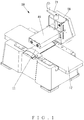
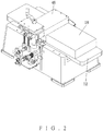
- a pusher for a planer comprises: a body 10, a planer 11 mounted on a top of the body 10, a movable control portion 20, a push member 46 arranged on a front end of the movable control portion 20 above the planer 11; wherein the planer 11 includes a cutter 13 and a drive shaft 14 in the body 10, the drive shaft 14 extends to a lower portion of the movable control portion 20, and a transmission portion 15 formed on a rear end of the body 10, a horizontal rod 16, a reduction wheel 17 connected with the horizontal rod 16, wherein a drive head 32 is formed on a rear end of the longitudinal rod 30.
- the drive head 32 of the longitudinal rod 30 is fitted with a first end of a lower belt 33, a second end of the lower belt 33 is fitted on a first receiving portion 35 of a transmission rod 34 above the longitudinal rod 30, and the idler pulley 61 is located inside a transmitting portion 31 and the drive head 32, an upper belt 36 is fitted on a front end of the lower belt 33, and the upper belt 36 is fitted on a wheel rod 40 and an auxiliary rod 54.
- the wheel rod 40 includes a second receiving portion 41 of a rear end thereof, a guiding portion 42 formed on a front end of the second receiving portion 41, a pushing wheel 45 fixed in the push member 46 of the wheel rod 40.
- the upper belt 36 is fitted on the second receiving portion 41, and the guiding portion 42 has a transmitting belt 43 fitted on a first end thereof.
- a second end of the transmitting belt 43 is fitted on an actuation rod 44 beside the wheel rod 40, the actuation rod 44 has a driving portion 47 formed on a rear end thereof so as to fit with the transmitting belt 43, and the actuation rod 44 has another pushing wheel 45 connected with the push member 46.
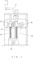
- the auxiliary rod 54 is supported on an auxiliary abutting block 50 inserted onto a positioning rod 52 which is mounted on a base 51, and a returning spring 53 is fitted on the positioning rod 52 between the base 51 and the auxiliary abutting block 50.
- the movable control portion 20 includes a rotary shaft 21 mounted on an upper end of the movable control portion 20 and extending to the movable control portion 20 inwardly.
- the movable control portion 20 includes a movable pedestal 22 connected with the wheel rod 40.
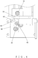
- the rotatable block 60 rotates along the longitudinal rod 30, a locking portion 63 is arranged on the body 10 inside of the arcuate orifice 62 so that after the lower belt 33 is fitted with the drive head 32 of the longitudinal rod 30 and the first receiving portion 35 of the transmission rod 34 to control the rotatable block 60 to rotate, and the idler pulley 61 of the rotatable block 60 abuts against the lower belt 33 outward, and the rotatable block 60 is locked with the locking portion 63 by ways of a screw bolt.
- the lower belt 33 is tightened, released, fixed, and detached easily by ways of the rotatable block 60 and the idler pulley 61 easily.
- the movable pedestal 22 of the movable control portion 20 lifts and descends, and the auxiliary abutting block 50 is pushed upward by the returning spring 53, such that when the push member 46 is pushed to any heights, the upper belt 36 is tightened.
- a wood 18 is pushed to the planer 11 from a platform 12, the wood 18 contacts with the pushing wheel 45 of the push member 46, and a user rotates the rotary shaft 21 to control the pushing wheel 45 to press the wood 18.
- the drive shaft 14 transmits kinetic energy to the movable control portion 20 to urge the pushing wheel 45 to rotate synchronously, and the drive shaft 14 drives the pushing wheel 45 to rotate slowly via the reduction wheel 17, thus pushing the wood 18 slowly.
- the wood 18 is pressed and pushed by the pushing wheel 45 to be planed automatically.
Landscapes
- Life Sciences & Earth Sciences (AREA)
- Engineering & Computer Science (AREA)
- Mechanical Engineering (AREA)
- Wood Science & Technology (AREA)
- Forests & Forestry (AREA)
- Milling, Drilling, And Turning Of Wood (AREA)
Priority Applications (1)
| Application Number | Priority Date | Filing Date | Title |
|---|---|---|---|
| EP19201799.4A EP3804928A1 (fr) | 2019-10-07 | 2019-10-07 | Poussoir pour raboteuse |
Applications Claiming Priority (1)
| Application Number | Priority Date | Filing Date | Title |
|---|---|---|---|
| EP19201799.4A EP3804928A1 (fr) | 2019-10-07 | 2019-10-07 | Poussoir pour raboteuse |
Publications (1)
| Publication Number | Publication Date |
|---|---|
| EP3804928A1 true EP3804928A1 (fr) | 2021-04-14 |
Family
ID=68172144
Family Applications (1)
| Application Number | Title | Priority Date | Filing Date |
|---|---|---|---|
| EP19201799.4A Withdrawn EP3804928A1 (fr) | 2019-10-07 | 2019-10-07 | Poussoir pour raboteuse |
Country Status (1)
| Country | Link |
|---|---|
| EP (1) | EP3804928A1 (fr) |
Citations (2)
| Publication number | Priority date | Publication date | Assignee | Title |
|---|---|---|---|---|
| EP0321390A2 (fr) * | 1987-12-15 | 1989-06-21 | Mida - Maquinas Industriais Do Ave, Lda. | Système d'avance sur une machine de travail du bois |
| US20100000630A1 (en) * | 2008-07-07 | 2010-01-07 | Bor-Yann Chuang | Work piece feeding and conveying device for a planing machine |
-
2019
- 2019-10-07 EP EP19201799.4A patent/EP3804928A1/fr not_active Withdrawn
Patent Citations (2)
| Publication number | Priority date | Publication date | Assignee | Title |
|---|---|---|---|---|
| EP0321390A2 (fr) * | 1987-12-15 | 1989-06-21 | Mida - Maquinas Industriais Do Ave, Lda. | Système d'avance sur une machine de travail du bois |
| US20100000630A1 (en) * | 2008-07-07 | 2010-01-07 | Bor-Yann Chuang | Work piece feeding and conveying device for a planing machine |
Similar Documents
| Publication | Publication Date | Title |
|---|---|---|
| AU2019101199A4 (en) | Pusher for Planer | |
| US10265840B2 (en) | Adjustable fastener-driving tool support system | |
| US7575140B2 (en) | Abutment adjusting device for nail gun | |
| EP2165806B1 (fr) | Cloueuse avec dispositif de sécurité intégré | |
| US20110314982A1 (en) | Sheet cutter and belt processing tool | |
| CN108787854A (zh) | 一种自动下料的冲压件一次成型装置 | |
| CN109048321B (zh) | 一种麦克风用直滑式电位器的全自动组装设备 | |
| GB2443073A (en) | An adjustable support shoe for a reciprocating saw | |
| JPH05277613A (ja) | リベット締め機 | |
| US20170266741A1 (en) | Sliding table type circular sawing machine | |
| US5544801A (en) | Fastening device for belt connectors | |
| US20060042441A1 (en) | Kickback-inhibiting devices for cutting devices | |
| US8381624B2 (en) | Band saw | |
| CN109500345B (zh) | 阀门铭牌装订机 | |
| EP1884322A1 (fr) | Outil enfonceur | |
| US2770804A (en) | Stapling machine | |
| CA3048825C (fr) | Poussoir pour raboteuse | |
| US11097443B2 (en) | Pusher for planer | |
| US6305209B1 (en) | Workpiece blanking apparatus | |
| GB2082977A (en) | Hoop-forming apparatus for steel straps | |
| US20140338505A1 (en) | Driving-in device | |
| US20190283268A1 (en) | Wood planing machine having both manual and automatic planing wood function | |
| US7392830B2 (en) | Micro-adjustment device for the angle stop plank of a planer | |
| CN109866023B (zh) | 一种扳扣的自动组装工艺 | |
| KR20090129313A (ko) | 금속 판재의 절개홈 이격 장치 |
Legal Events
| Date | Code | Title | Description |
|---|---|---|---|
| PUAI | Public reference made under article 153(3) epc to a published international application that has entered the european phase |
Free format text: ORIGINAL CODE: 0009012 |
|
| STAA | Information on the status of an ep patent application or granted ep patent |
Free format text: STATUS: THE APPLICATION HAS BEEN PUBLISHED |
|
| AK | Designated contracting states |
Kind code of ref document: A1 Designated state(s): AL AT BE BG CH CY CZ DE DK EE ES FI FR GB GR HR HU IE IS IT LI LT LU LV MC MK MT NL NO PL PT RO RS SE SI SK SM TR |
|
| AX | Request for extension of the european patent |
Extension state: BA ME |
|
| STAA | Information on the status of an ep patent application or granted ep patent |
Free format text: STATUS: REQUEST FOR EXAMINATION WAS MADE |
|
| 17P | Request for examination filed |
Effective date: 20211014 |
|
| RBV | Designated contracting states (corrected) |
Designated state(s): AL AT BE BG CH CY CZ DE DK EE ES FI FR GB GR HR HU IE IS IT LI LT LU LV MC MK MT NL NO PL PT RO RS SE SI SK SM TR |
|
| STAA | Information on the status of an ep patent application or granted ep patent |
Free format text: STATUS: EXAMINATION IS IN PROGRESS |
|
| 17Q | First examination report despatched |
Effective date: 20221118 |
|
| STAA | Information on the status of an ep patent application or granted ep patent |
Free format text: STATUS: THE APPLICATION HAS BEEN WITHDRAWN |
|
| 18W | Application withdrawn |
Effective date: 20230227 |