EP3805096A1 - Aéronef et système d'aile pliable - Google Patents
Aéronef et système d'aile pliable Download PDFInfo
- Publication number
- EP3805096A1 EP3805096A1 EP19201846.3A EP19201846A EP3805096A1 EP 3805096 A1 EP3805096 A1 EP 3805096A1 EP 19201846 A EP19201846 A EP 19201846A EP 3805096 A1 EP3805096 A1 EP 3805096A1
- Authority
- EP
- European Patent Office
- Prior art keywords
- segment
- wing
- folding wing
- aircraft
- strut
- Prior art date
- Legal status (The legal status is an assumption and is not a legal conclusion. Google has not performed a legal analysis and makes no representation as to the accuracy of the status listed.)
- Granted
Links
Images


Classifications
-
- B—PERFORMING OPERATIONS; TRANSPORTING
- B64—AIRCRAFT; AVIATION; COSMONAUTICS
- B64C—AEROPLANES; HELICOPTERS
- B64C3/00—Wings
- B64C3/38—Adjustment of complete wings or parts thereof
- B64C3/56—Folding or collapsing to reduce overall dimensions of aircraft
-
- B—PERFORMING OPERATIONS; TRANSPORTING
- B64—AIRCRAFT; AVIATION; COSMONAUTICS
- B64C—AEROPLANES; HELICOPTERS
- B64C29/00—Aircraft capable of landing or taking-off vertically, e.g. vertical take-off and landing [VTOL] aircraft
- B64C29/0008—Aircraft capable of landing or taking-off vertically, e.g. vertical take-off and landing [VTOL] aircraft having its flight directional axis horizontal when grounded
-
- Y—GENERAL TAGGING OF NEW TECHNOLOGICAL DEVELOPMENTS; GENERAL TAGGING OF CROSS-SECTIONAL TECHNOLOGIES SPANNING OVER SEVERAL SECTIONS OF THE IPC; TECHNICAL SUBJECTS COVERED BY FORMER USPC CROSS-REFERENCE ART COLLECTIONS [XRACs] AND DIGESTS
- Y02—TECHNOLOGIES OR APPLICATIONS FOR MITIGATION OR ADAPTATION AGAINST CLIMATE CHANGE
- Y02T—CLIMATE CHANGE MITIGATION TECHNOLOGIES RELATED TO TRANSPORTATION
- Y02T50/00—Aeronautics or air transport
- Y02T50/10—Drag reduction
Definitions
- the present invention relates to a folding wing system for an aircraft.
- the invention further relates to an aircraft equipped with two such folding wing systems.
- Conventional folding wing systems are designed for folding the wings of the aircraft after the aircraft has landed safely, particularly to reduce the required taxi and/or parking space or for running the aircraft as a road vehicle.
- the conventional folding wing systems are designed to be robust during flight and to have a mechanism for folding that is as lightweight as possible. This is achieved, e.g., according to US 2010/0051742 A1 , by a cable actuation for folding an outer wing section and an inner wing section of the folding wing such that the two wing sections move in concert. While this allows for a lightweight construction the wing sections cannot be moved individually and the stability of the folded wing is rather low.
- this object is achieved with a folding wing system for an aircraft, comprising:
- the strut connecting the support structure and the second segment ensures robustness of the folding wing system in any position throughout the whole folding process.
- the strut is safely supported on the support structure and guided in the bearing of the second segment.
- such a folding wing system facilitates a design where the distal end of the second segment in the folded position of the wing can support the aircraft on the ground. The forces and torques arising in this position can be absorbed by the first and second segments in cooperation with the strut.
- the strut provides additional rigidity and robustness to the wing when the aircraft is in flight.
- the strut facilitates a robust wing structure for an aircraft and still allows for a lightweight construction of the wing segments and the folding wing system as such.
- the two drives provide a high flexibility by allowing to control the first and second segments largely independently from one another such that, e.g., the distance between the distal end of the second segment and/or the rotation of the first and second wing segments with respect to the support structure can be chosen freely to a large extent. This allows to control the trajectory of the distal end of the second segment and thus the distance of the contact points on the ground.
- the folding wing system is, therefore, particularly suitable for vertical take-off and landing (VTOL) aircrafts.
- the wing comprises a third segment, wherein a proximal end of the third segment is connected to the distal end of the second segment via a fourth hinged connection, and wherein the wing is foldable from the cruise position to the folded position by pivoting the first segment up, the second segment down and the third segment up.
- This additional third wing segment increases the wing surface and the aspect ratio of the wing, thus reducing induced drag and therefore increasing efficiency.
- the second benefit is that the increased surface allows to reduce the stall speed and therefore to transition to horizontal flight at a lower forward speed.
- the wing of three segments folds smaller than a wing of two segments.
- the third segment provides an option for mounting, e.g., a propulsion unit on its distal end, which does not interfere with the folding process and is distanced from the ground when the third segment is folded upwards, away from the ground.
- the distal end of the second segment advantageously has a landing foot which is accommodated in the wing in the cruise position and exposed in the folded position. Due to the accommodation, the landing foot does not induce additional drag or negatively affect the air flow about the wing during cruise flight.
- the landing foot may, e.g., be accommodated therein when the wing is in its cruise position.
- the landing foot may include a shock absorber, preferably an oleostrut.
- the first and second drives are located in the support structure.
- the benefit thereof is twofold: Firstly, the shift of mass towards the support structure reduces the mass of the wing segments and/or the strut and, hence, increases the manoeuvrability about the aircraft's roll axis.
- folding and unfolding of the wing is simplified as the required driving of the hinges and/or the bearing is eased by the reduced mass of the elements to be driven.
- the first and second drives may be of any type known in the art, e.g., comprising an electric motor, wherein the motor's stator constitutes one member of the hinged connection and the motor's rotor constitutes the other member of the hinged connection.
- the first segment has a lever and one of the first and second drives is a linear drive, preferably a lockable linear drive, which is supported on the support structure and coupled to the lever.
- the strut has an arm and the other one of the first and second drives is a linear drive, preferably a lockable linear drive, which is supported on the support structure and coupled to the arm.
- the optional locking of the linear drives enhances safety and hinders unintended folding or unfolding.
- the torque applicable to the first segment and/or to the strut can easily be customised by the respective lengths of the lever or arm.
- the angles between the lever and the first segment and/or between the arm and the strut as well as the support of the respective linear drive on the support structure may be customised to fulfil torque requirements.
- first and third hinged connections may be mutually distanced, however, in a favourable embodiment the first and third hinged connections share a common hinge axis. In this case the respective proximal ends of both the first segment and the strut are pivoted on the common hinge axis. Such an arrangement reduces the required mounting space in the support structure and the complexity thereof.
- the support structure comprises two parallel, mutually spaced supporting plates mounting a shaft therebetween which forms the hinge axis of at least one of the first and third hinged connections.
- each supporting plate is substantially C-shaped. This, on the one hand, makes use of the available fuselage space, and, on the other hand, allows to easily connect two mirrored folding wing systems at the ends of their C or integrally form a plate consisting of two mirrored C-shaped plates, thus increasing the rigidity of the mounting on the aircraft.
- the wing has a channel in which the strut is accommodated in the cruise position of the wing.
- an aerodynamic accommodation of the strut is achieved such that the drag of the aircraft during cruise is mitigated.
- the strut is not limited to a specific form.
- the strut may be, e.g., angled or bent.
- the first and third hinged connections share a common hinge axis and the strut is simply straight, it can be completely accommodated in the channel.
- the bearing supports the distal end of the strut and provides for a combined slidable, i.e., linear, and pivotable movement of the distal end of the strut with respect to the second segment.
- the bearing comprises a groove on the second segment running in said longitudinal direction and, sliding in the groove, a base for supporting the distal end of the strut. This arrangement results in a simple, safe and easily maintainable bearing.
- the base is releasably lockable in the groove.
- the base and thus the distal end of the strut can be releasably locked in a predetermined or even in any position along the second segment, e.g., in the cruise position of the wing to prevent unintended folding and/or in the folded position to prevent unintended sliding.
- the strut may be a shock absorber, preferably an oleostrut.
- the invention creates an aircraft having a fuselage and two folding wing systems of the aforementioned type, each of which folding wing systems is mounted on the fuselage.
- the support structure of each folding wing system is mounted on the fuselage rotatably about a roll axis of the aircraft.
- the wings of such an aircraft can be oriented vertically, such that the aircraft could land on a vertical wall, e.g., a building, if the distal end of the second segment can be supported or affixed thereon.
- the wing of one of said folding wing systems is foldable independently of the wing of the other one of said folding wing systems.
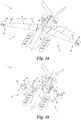
- An aircraft 1 shown in Figs. 1a and 1b has two folding wing systems 2 mounted on and extending from the aircraft's fuselage 3.
- Each folding wing system 2 has a wing 4 that is foldable from a cruise position ( Fig. 1a ) to a folded position ( Fig. 1b ) and back.
- the folding wing system 2 comprises a support structure 5 which is mountable on the fuselage 3 and supports the wing 4.
- the wing 4 is segmented into at least a first segment 6 and a second segment 7.
- the support structure 5 is connected to a proximal end 8, i.e., proximal to the support structure 5, of the first segment 6 via a first hinged connection 9.
- the first segment 5 is connected at its distal end 10, i.e., distal to the support structure 5 and opposite to the proximal end 8, to a proximal end 11 of the second segment 7 via a second hinged connection 12.
- the folding wing system 2 further comprises a strut 13, to a proximal end 14 of which, i.e., proximal to the support structure 5, the support structure 5 is connected via a third hinged connection 15.
- a distal end 16 of the strut 13 is supported by a bearing 17 of the second wing segment 7 in a manner both slidable along a longitudinal direction 18 and pivotable about an axis 19 ( Fig. 3 ) which is transverse to the longitudinal direction 18.
- the longitudinal direction 18 runs from the proximal end 11 to the distal end 20 of the second segment 7.
- the folding wing system 2 For driving a transition between the cruise position ( Fig. 1a ) and the folded position ( Fig. 1b ), i.e., for folding and unfolding the wing 4, the folding wing system 2 has a first drive 21 and a second drive 22.
- the first drive 21 drives either the first or the third hinged connection 9, 15.
- the second drive 22 drives either the second hinged connection 12, the bearing 17, or that one of the first and third hinged connection 9, 15 which is not driven by the first drive 21. Further drives may optionally be deployed.
- the two drives i.e., the first and second drives 21, 22, pivot the first segment 6 up and the second segment 7 down.
- the two drives 21, 22 may work simultaneously or with a respective time shift or at different speeds. In this way, the trajectory of the distal end 20 of the second segment 7 can be controlled in a completely arbitrary manner.
- the wing 4 is not necessarily fully collapsed in the folded position.
- this pivoting by the two drives 21, 22 is reversed.
- "up" and “down” relate to a general orientation of the folding wing system 2, i.e., the folding wing system 2 being mounted on the aircraft 1 and the aircraft 1 being in a horizontal position.
- the wing 4 comprises an optional third segment 23.
- a proximal end 24 of the third segment 23, i.e., proximal to the support structure 5, is connected to the distal end 20 of the second segment 7 via a fourth hinged connection 25 such that the wing 4 is folded by pivoting the first segment 6 up, the second segment 7 down and the third segment 23 up, thus forming a zig-zag pattern.
- the fourth hinged connection 25 may be pivoted by a separate drive, a cable actuation, a lever mechanism, or the like, as known in the art.
- the distal end 20 of the second segment 7 is generally the lowest part of the folding wing system 2 in the folded position of the wing 4. Hence, when the aircraft 1 is on the ground 26 the distal end 20 of the second segment 7 will be in contact with the ground 26.
- said distal end 20 has an optional landing foot 27.
- the landing foot 27 may be or comprise, e.g., a skid, a wheel or the like as known in the art.
- the landing foot 27 is a spreadable bracket 28 which is spread on the ground 26 and collapsed otherwise ( Fig. 4 ).
- the landing foot 27 is exposed in the folded position of the wing 4, whereas it is optionally accommodated in the wing 4, e.g., in a recess 29 of the third segment 23, in the cruise position of the wing 4 ( Fig. 4 ).
- the landing foot 27 may have a shock absorber, e.g., an oleostrut for cushioning impacts.
- the support structure 5 may be of any type known in the art, e.g., a frame or rack structure.
- the support structure 5 comprises two supporting plates 30 that are parallel to each other and mutually spaced at a distance D. Between the two supporting plates 30, one or more shafts 31 or rods 32, 33 are mounted which connect the supporting plates 30.
- One of said shafts 31 or rods 32, 33, here: the shaft 31, optionally forms a hinge axis 34 of the first and/or the third hinged connection 9, 15 as will be explained in greater detail below.
- both the first and the second drive 21, 22 are located in the support structure 5, i.e., the drives 21, 22 do not protrude from the support structure 5.
- both the first hinged connection 9 and the third hinged connection 15 are each driven by a respective linear drive 35, 36, i.e., each of the first and the second drive 21, 22 is a linear drive 35, 36.
- one linear drive 35 is supported on the support structure 5, (here: on a first rod 32) and is coupled to the first segment 6.
- the first segment 6 has a lever 37 to which the linear drive 35 is coupled.
- the lever 37 generally protrudes from the first segment 6 but may alternatively coincide with the first segment 6 such that the linear drive 35 is coupled to the first segment 6 at a (lever) distance from the hinge axis 34.
- the strut 13 has an arm 38 optionally protruding from the strut 13 and the other linear drive 36 is supported on the support structure 5 (here: on a second rod 33) and coupled to the arm 38.
- Each of the linear drives 35, 36 could, e.g., be one or more spindle drives, hydraulic cylinders, etc.
- first and/or the second drive 21, 22 could alternatively be another drive known in the art, e.g., an electric motor, the stator of which constitutes one member of the respective hinged connection 9, 15 and the rotor of which constitutes the other member of the hinged connection 9, 15. All the abovementioned variants of first and/or second drives 21, 22 could optionally be lockable in at least one position.
- the first and third hinged connections 9, 15 may be spaced from each other on the support structure 5 such that they have different hinge axes. However, as shown in Fig. 2 , the first and third hinged connections 9, 15 share the common hinge axis 34 which is formed by the shaft 31 in this example.
- the wing 4 may have a channel 39 in which the strut 13 is accommodated in the cruise position of the wing 4 when the strut 13 is straight and the first and third hinged connections 9, 15 share the hinge axis 34.
- the first and third hinge axis are distanced from each other and/or the strut 13 has a different form, e.g., is bent or angled, the strut 13 may be partially accomodatable in the channel 39 of the wing 4 in its cruise position.
- the bearing 17 of the second segment 7 comprises a groove 40 on the second segment 7 running in the longitudinal direction 18 and, sliding in the groove 40, a base 41.
- the base 41 supports the distal end 16 of the strut 13.
- the base 41 may, for example, be a pin (not visible) directed along the transverse axis 19 and passing through an opening in the distal end 16 of the strut 13; the pin, i.e., the base 41 in this case, is both slidable and pivotable in the groove 40 which may have a T-shaped cross-section for this purpose.
- the base 41 is merely slidable in the groove 40 and pivotably supports the distal end 16 of the strut 13.
- the base 41 may optionally be driven in the groove 40, e.g., be a spindle nut to a driven threaded spindle inside the groove 40.
- the base 41 is releasably lockable in the groove 40, e.g., in the cruise position to prohibit unintended folding of the wing 4 or in any folded position to achieve a robust landing support.
- the strut 13 is optionally a shock absorber, e.g., an oleostrut for cushioning possible impacts on the wing 4 when folded.
- each supporting plate 30 may be substantially C-shaped such that two mirrored folding wing systems 2 easily fit into the typically circular cross-section of the fuselage 3 and still leave a central window 42 inside the fuselage 3 of the aircraft 1.
- two mirrored C-shaped supporting plates 30 may be formed integrally as a single circular or ring-shaped plate.
- each folding wing system 2 can be mounted on the fuselage 3 rotatably about a roll axis 43 of the fuselage.
- the supporting plates 30 could be mounted on a shaft passing through the central window 42.
- the wings 4 could be rotated in a vertical position parallel to a yaw axis 44 such that the aircraft 1 could land on a vertical wall, e.g., on a building, if the distal end 20 of the second segment 7 can be supported or affixed thereon.
- each folding wing system 2 is foldable independently of the wing 4 of the other folding wing system 2.
- the combined pivoting and folding of each wing 4 allows to level the fuselage 3 of the landed aircraft 1, e.g., when the ground 26 is uneven or inclined.
- said independent folding allows to adjust a height H of the fuselage 3 above ground 26.
- the distal end 20 of the second segment 7 of one of the wings 4 could even rest against a substantially vertical wall.
- the fuselage 3 optionally comprises a third landing foot (not shown) in addition to the two landing feet 27, e.g., a landing foot below the nose or tail of the aircraft 1.
- the aircraft 1 is optionally a vertical take-off and landing (VTOL) aircraft 1.
- the third segment 23 of the wing 4 may comprise a propulsion unit 45, e.g., on a wing tip 46. With the third segment 23 folding up, the propulsion unit 45 is distanced from the ground 26 ( Fig. 3 ) and does not hinder the folding procedure.
- the propulsion unit 45 may be tiltable about an axis 48 to produce thrust parallel to a yaw axis 44 or, after tilting, to the roll axis 43 of the aircraft 1.
- the propulsion unit 45 mounted at the wing tip 46 would follow the pivoting movement of the tip segment 23.
- the propulsion unit may be further articulated on the respective wing tip 46 about a further axis 49 parallel to the roll axis 43 at the wing tip 46.
Landscapes
- Engineering & Computer Science (AREA)
- Mechanical Engineering (AREA)
- Aviation & Aerospace Engineering (AREA)
- Tires In General (AREA)
Priority Applications (3)
| Application Number | Priority Date | Filing Date | Title |
|---|---|---|---|
| EP19201846.3A EP3805096B1 (fr) | 2019-10-08 | 2019-10-08 | Aéronef et système d'aile pliable |
| US17/766,413 US12116124B2 (en) | 2019-10-08 | 2020-09-04 | Aircraft and folding wing system |
| PCT/EP2020/074774 WO2021069156A1 (fr) | 2019-10-08 | 2020-09-04 | Aéronef et système d'aile pliable |
Applications Claiming Priority (1)
| Application Number | Priority Date | Filing Date | Title |
|---|---|---|---|
| EP19201846.3A EP3805096B1 (fr) | 2019-10-08 | 2019-10-08 | Aéronef et système d'aile pliable |
Publications (3)
| Publication Number | Publication Date |
|---|---|
| EP3805096A1 true EP3805096A1 (fr) | 2021-04-14 |
| EP3805096C0 EP3805096C0 (fr) | 2023-07-26 |
| EP3805096B1 EP3805096B1 (fr) | 2023-07-26 |
Family
ID=68242274
Family Applications (1)
| Application Number | Title | Priority Date | Filing Date |
|---|---|---|---|
| EP19201846.3A Active EP3805096B1 (fr) | 2019-10-08 | 2019-10-08 | Aéronef et système d'aile pliable |
Country Status (3)
| Country | Link |
|---|---|
| US (1) | US12116124B2 (fr) |
| EP (1) | EP3805096B1 (fr) |
| WO (1) | WO2021069156A1 (fr) |
Cited By (2)
| Publication number | Priority date | Publication date | Assignee | Title |
|---|---|---|---|---|
| CN116674748A (zh) * | 2022-04-12 | 2023-09-01 | 中国航空工业集团公司西安飞机设计研究所 | 一种飞机空投货箱 |
| EP4410666A1 (fr) * | 2023-01-31 | 2024-08-07 | Rohr, Inc. | Aile pliable pour un aéronef |
Families Citing this family (5)
| Publication number | Priority date | Publication date | Assignee | Title |
|---|---|---|---|---|
| DE102020105899A1 (de) * | 2020-03-05 | 2021-09-09 | Innotec Lightweight Engineering & Polymer Technology Gmbh | Fluggerät mit mehreren Flugmodi und Verfahren zu dessen Betreiben |
| US11820493B2 (en) * | 2020-08-24 | 2023-11-21 | Sonin Hybrid, LLC | Landing support assembly for aerial vehicles |
| CN113665792B (zh) * | 2021-08-11 | 2023-12-05 | 广东空天科技研究院 | 一种折叠机翼及适用于折叠机翼高承载状态的锁定机构 |
| US12312076B2 (en) * | 2022-11-04 | 2025-05-27 | Changzhou Taifei Electric Co., Ltd. | Electric vertical take-off and landing aircraft |
| CN119319911B (zh) * | 2024-10-16 | 2025-11-04 | 北京工业大学 | 一种变后掠内外伸缩翼飞行器变体结构 |
Citations (11)
| Publication number | Priority date | Publication date | Assignee | Title |
|---|---|---|---|---|
| JPS5069799A (fr) * | 1973-10-22 | 1975-06-10 | ||
| US20020060267A1 (en) * | 2000-09-26 | 2002-05-23 | Arie Yavnai | Unmanned mobile device |
| US6619584B1 (en) * | 2002-03-11 | 2003-09-16 | Robin Haynes | Road/air vehicle |
| US20100019080A1 (en) * | 2008-07-22 | 2010-01-28 | Terrafugia, Inc. | Folding Wing Root Mechanism |
| US20100051742A1 (en) | 2008-07-22 | 2010-03-04 | Terrafugia, Inc,; | Folding Wing & Locking Mechanism |
| US20100230532A1 (en) * | 2006-01-06 | 2010-09-16 | Carl Curtis Dietrich | Roadable aircraft with folding wings and integrated bumpers and lighting |
| WO2012012752A9 (fr) | 2010-07-23 | 2012-06-07 | Terrafugia, Inc. | Aéronef pouvant circuler sur la route et systèmes associés |
| CN103129735A (zh) | 2013-03-08 | 2013-06-05 | 北京航空航天大学 | 三段双折叠翼 |
| US20140014764A1 (en) * | 2012-07-10 | 2014-01-16 | Gert Magnus Lundgren | Vertical takeoff and landing roadable vehicle |
| US20170029094A1 (en) * | 2014-04-04 | 2017-02-02 | Airbus Operations Limited | Aircraft wing with a wing tip device and a strut |
| US20170283052A1 (en) * | 2016-04-05 | 2017-10-05 | Swift Engineering, Inc. | Rotating wing assemblies for tailsitter aircraft |
Family Cites Families (3)
| Publication number | Priority date | Publication date | Assignee | Title |
|---|---|---|---|---|
| US5050817A (en) * | 1989-10-16 | 1991-09-24 | Miller Harvey R | Combined road and aircraft vehicle |
| US8267347B2 (en) * | 2007-01-22 | 2012-09-18 | Yan Goldshteyn | Winging car |
| RU2018130978A (ru) * | 2016-01-29 | 2020-03-02 | ДжейДжи ЭНТРЕПРЕНЬЮРИЭЛ ЭНТЕРПРАЙСЕЗ ЛЛС | Авиационный автомобиль и соответствующие признаки |
-
2019
- 2019-10-08 EP EP19201846.3A patent/EP3805096B1/fr active Active
-
2020
- 2020-09-04 US US17/766,413 patent/US12116124B2/en active Active
- 2020-09-04 WO PCT/EP2020/074774 patent/WO2021069156A1/fr not_active Ceased
Patent Citations (11)
| Publication number | Priority date | Publication date | Assignee | Title |
|---|---|---|---|---|
| JPS5069799A (fr) * | 1973-10-22 | 1975-06-10 | ||
| US20020060267A1 (en) * | 2000-09-26 | 2002-05-23 | Arie Yavnai | Unmanned mobile device |
| US6619584B1 (en) * | 2002-03-11 | 2003-09-16 | Robin Haynes | Road/air vehicle |
| US20100230532A1 (en) * | 2006-01-06 | 2010-09-16 | Carl Curtis Dietrich | Roadable aircraft with folding wings and integrated bumpers and lighting |
| US20100019080A1 (en) * | 2008-07-22 | 2010-01-28 | Terrafugia, Inc. | Folding Wing Root Mechanism |
| US20100051742A1 (en) | 2008-07-22 | 2010-03-04 | Terrafugia, Inc,; | Folding Wing & Locking Mechanism |
| WO2012012752A9 (fr) | 2010-07-23 | 2012-06-07 | Terrafugia, Inc. | Aéronef pouvant circuler sur la route et systèmes associés |
| US20140014764A1 (en) * | 2012-07-10 | 2014-01-16 | Gert Magnus Lundgren | Vertical takeoff and landing roadable vehicle |
| CN103129735A (zh) | 2013-03-08 | 2013-06-05 | 北京航空航天大学 | 三段双折叠翼 |
| US20170029094A1 (en) * | 2014-04-04 | 2017-02-02 | Airbus Operations Limited | Aircraft wing with a wing tip device and a strut |
| US20170283052A1 (en) * | 2016-04-05 | 2017-10-05 | Swift Engineering, Inc. | Rotating wing assemblies for tailsitter aircraft |
Cited By (2)
| Publication number | Priority date | Publication date | Assignee | Title |
|---|---|---|---|---|
| CN116674748A (zh) * | 2022-04-12 | 2023-09-01 | 中国航空工业集团公司西安飞机设计研究所 | 一种飞机空投货箱 |
| EP4410666A1 (fr) * | 2023-01-31 | 2024-08-07 | Rohr, Inc. | Aile pliable pour un aéronef |
Also Published As
| Publication number | Publication date |
|---|---|
| EP3805096C0 (fr) | 2023-07-26 |
| EP3805096B1 (fr) | 2023-07-26 |
| US20240308644A1 (en) | 2024-09-19 |
| WO2021069156A1 (fr) | 2021-04-15 |
| US12116124B2 (en) | 2024-10-15 |
Similar Documents
| Publication | Publication Date | Title |
|---|---|---|
| US12116124B2 (en) | Aircraft and folding wing system | |
| AU2020230338B2 (en) | Wing tilt actuation system for electric vertical take-off and landing (VTOL) aircraft | |
| EP1812251B9 (fr) | Vehicule personnel terrestre et aerien | |
| US8162253B2 (en) | Convertible vehicle for road, air, and water usage | |
| KR20160147851A (ko) | 접이식 윙팁 장치를 갖는 항공기 | |
| EP3204246B1 (fr) | Panneau d'aile centrale pour véhicule volant et son procédé de commande | |
| US20170113797A1 (en) | Convertible Aircraft | |
| GB2523970A (en) | Suspension structure with variable geometry of a turboprop engine on a structural element of an aircraft | |
| US20020195518A1 (en) | Combination fixed and rotating wing aircraft and land vehicle | |
| JP5588629B2 (ja) | 飛行機の垂直尾翼 | |
| US20210122461A1 (en) | Relocatable main landing gear | |
| CN114132495A (zh) | 一种旋固双翼机 | |
| US20210122462A1 (en) | Relocatable main landing gear | |
| CN108454825A (zh) | 着陆装置安装的翼型 | |
| NZ762347B2 (en) | Wing tilt actuation system for electric vertical take-off and landing (vtol) aircraft | |
| SK7493Y1 (sk) | Centroplán lietajúceho vozidla a spôsob jeho ovládania |
Legal Events
| Date | Code | Title | Description |
|---|---|---|---|
| PUAI | Public reference made under article 153(3) epc to a published international application that has entered the european phase |
Free format text: ORIGINAL CODE: 0009012 |
|
| STAA | Information on the status of an ep patent application or granted ep patent |
Free format text: STATUS: THE APPLICATION HAS BEEN PUBLISHED |
|
| AK | Designated contracting states |
Kind code of ref document: A1 Designated state(s): AL AT BE BG CH CY CZ DE DK EE ES FI FR GB GR HR HU IE IS IT LI LT LU LV MC MK MT NL NO PL PT RO RS SE SI SK SM TR |
|
| AX | Request for extension of the european patent |
Extension state: BA ME |
|
| STAA | Information on the status of an ep patent application or granted ep patent |
Free format text: STATUS: REQUEST FOR EXAMINATION WAS MADE |
|
| 17P | Request for examination filed |
Effective date: 20211006 |
|
| RBV | Designated contracting states (corrected) |
Designated state(s): AL AT BE BG CH CY CZ DE DK EE ES FI FR GB GR HR HU IE IS IT LI LT LU LV MC MK MT NL NO PL PT RO RS SE SI SK SM TR |
|
| GRAP | Despatch of communication of intention to grant a patent |
Free format text: ORIGINAL CODE: EPIDOSNIGR1 |
|
| STAA | Information on the status of an ep patent application or granted ep patent |
Free format text: STATUS: GRANT OF PATENT IS INTENDED |
|
| INTG | Intention to grant announced |
Effective date: 20230327 |
|
| GRAS | Grant fee paid |
Free format text: ORIGINAL CODE: EPIDOSNIGR3 |
|
| GRAA | (expected) grant |
Free format text: ORIGINAL CODE: 0009210 |
|
| STAA | Information on the status of an ep patent application or granted ep patent |
Free format text: STATUS: THE PATENT HAS BEEN GRANTED |
|
| RAP3 | Party data changed (applicant data changed or rights of an application transferred) |
Owner name: VOLARE GMBH |
|
| AK | Designated contracting states |
Kind code of ref document: B1 Designated state(s): AL AT BE BG CH CY CZ DE DK EE ES FI FR GB GR HR HU IE IS IT LI LT LU LV MC MK MT NL NO PL PT RO RS SE SI SK SM TR |
|
| REG | Reference to a national code |
Ref country code: CH Ref legal event code: EP |
|
| REG | Reference to a national code |
Ref country code: DE Ref legal event code: R096 Ref document number: 602019033423 Country of ref document: DE |
|
| REG | Reference to a national code |
Ref country code: IE Ref legal event code: FG4D |
|
| U01 | Request for unitary effect filed |
Effective date: 20230728 |
|
| U07 | Unitary effect registered |
Designated state(s): AT BE BG DE DK EE FI FR IT LT LU LV MT NL PT SE SI Effective date: 20230802 |
|
| REG | Reference to a national code |
Ref country code: LT Ref legal event code: MG9D |
|
| U20 | Renewal fee for the european patent with unitary effect paid |
Year of fee payment: 5 Effective date: 20231009 |
|
| PG25 | Lapsed in a contracting state [announced via postgrant information from national office to epo] |
Ref country code: GR Free format text: LAPSE BECAUSE OF FAILURE TO SUBMIT A TRANSLATION OF THE DESCRIPTION OR TO PAY THE FEE WITHIN THE PRESCRIBED TIME-LIMIT Effective date: 20231027 |
|
| PG25 | Lapsed in a contracting state [announced via postgrant information from national office to epo] |
Ref country code: IS Free format text: LAPSE BECAUSE OF FAILURE TO SUBMIT A TRANSLATION OF THE DESCRIPTION OR TO PAY THE FEE WITHIN THE PRESCRIBED TIME-LIMIT Effective date: 20231126 |
|
| PG25 | Lapsed in a contracting state [announced via postgrant information from national office to epo] |
Ref country code: RS Free format text: LAPSE BECAUSE OF FAILURE TO SUBMIT A TRANSLATION OF THE DESCRIPTION OR TO PAY THE FEE WITHIN THE PRESCRIBED TIME-LIMIT Effective date: 20230726 Ref country code: NO Free format text: LAPSE BECAUSE OF FAILURE TO SUBMIT A TRANSLATION OF THE DESCRIPTION OR TO PAY THE FEE WITHIN THE PRESCRIBED TIME-LIMIT Effective date: 20231026 Ref country code: IS Free format text: LAPSE BECAUSE OF FAILURE TO SUBMIT A TRANSLATION OF THE DESCRIPTION OR TO PAY THE FEE WITHIN THE PRESCRIBED TIME-LIMIT Effective date: 20231126 Ref country code: HR Free format text: LAPSE BECAUSE OF FAILURE TO SUBMIT A TRANSLATION OF THE DESCRIPTION OR TO PAY THE FEE WITHIN THE PRESCRIBED TIME-LIMIT Effective date: 20230726 Ref country code: GR Free format text: LAPSE BECAUSE OF FAILURE TO SUBMIT A TRANSLATION OF THE DESCRIPTION OR TO PAY THE FEE WITHIN THE PRESCRIBED TIME-LIMIT Effective date: 20231027 |
|
| PG25 | Lapsed in a contracting state [announced via postgrant information from national office to epo] |
Ref country code: PL Free format text: LAPSE BECAUSE OF FAILURE TO SUBMIT A TRANSLATION OF THE DESCRIPTION OR TO PAY THE FEE WITHIN THE PRESCRIBED TIME-LIMIT Effective date: 20230726 |
|
| PG25 | Lapsed in a contracting state [announced via postgrant information from national office to epo] |
Ref country code: ES Free format text: LAPSE BECAUSE OF FAILURE TO SUBMIT A TRANSLATION OF THE DESCRIPTION OR TO PAY THE FEE WITHIN THE PRESCRIBED TIME-LIMIT Effective date: 20230726 |
|
| REG | Reference to a national code |
Ref country code: DE Ref legal event code: R097 Ref document number: 602019033423 Country of ref document: DE |
|
| PG25 | Lapsed in a contracting state [announced via postgrant information from national office to epo] |
Ref country code: SM Free format text: LAPSE BECAUSE OF FAILURE TO SUBMIT A TRANSLATION OF THE DESCRIPTION OR TO PAY THE FEE WITHIN THE PRESCRIBED TIME-LIMIT Effective date: 20230726 Ref country code: RO Free format text: LAPSE BECAUSE OF FAILURE TO SUBMIT A TRANSLATION OF THE DESCRIPTION OR TO PAY THE FEE WITHIN THE PRESCRIBED TIME-LIMIT Effective date: 20230726 Ref country code: ES Free format text: LAPSE BECAUSE OF FAILURE TO SUBMIT A TRANSLATION OF THE DESCRIPTION OR TO PAY THE FEE WITHIN THE PRESCRIBED TIME-LIMIT Effective date: 20230726 Ref country code: CZ Free format text: LAPSE BECAUSE OF FAILURE TO SUBMIT A TRANSLATION OF THE DESCRIPTION OR TO PAY THE FEE WITHIN THE PRESCRIBED TIME-LIMIT Effective date: 20230726 Ref country code: SK Free format text: LAPSE BECAUSE OF FAILURE TO SUBMIT A TRANSLATION OF THE DESCRIPTION OR TO PAY THE FEE WITHIN THE PRESCRIBED TIME-LIMIT Effective date: 20230726 |
|
| PG25 | Lapsed in a contracting state [announced via postgrant information from national office to epo] |
Ref country code: MC Free format text: LAPSE BECAUSE OF FAILURE TO SUBMIT A TRANSLATION OF THE DESCRIPTION OR TO PAY THE FEE WITHIN THE PRESCRIBED TIME-LIMIT Effective date: 20230726 |
|
| PLBE | No opposition filed within time limit |
Free format text: ORIGINAL CODE: 0009261 |
|
| STAA | Information on the status of an ep patent application or granted ep patent |
Free format text: STATUS: NO OPPOSITION FILED WITHIN TIME LIMIT |
|
| 26N | No opposition filed |
Effective date: 20240429 |
|
| PG25 | Lapsed in a contracting state [announced via postgrant information from national office to epo] |
Ref country code: IE Free format text: LAPSE BECAUSE OF NON-PAYMENT OF DUE FEES Effective date: 20231008 |
|
| PG25 | Lapsed in a contracting state [announced via postgrant information from national office to epo] |
Ref country code: IE Free format text: LAPSE BECAUSE OF NON-PAYMENT OF DUE FEES Effective date: 20231008 |
|
| U20 | Renewal fee for the european patent with unitary effect paid |
Year of fee payment: 6 Effective date: 20241004 |
|
| PGFP | Annual fee paid to national office [announced via postgrant information from national office to epo] |
Ref country code: GB Payment date: 20241024 Year of fee payment: 6 |
|
| PGFP | Annual fee paid to national office [announced via postgrant information from national office to epo] |
Ref country code: CH Payment date: 20241101 Year of fee payment: 6 |
|
| PG25 | Lapsed in a contracting state [announced via postgrant information from national office to epo] |
Ref country code: CY Free format text: LAPSE BECAUSE OF FAILURE TO SUBMIT A TRANSLATION OF THE DESCRIPTION OR TO PAY THE FEE WITHIN THE PRESCRIBED TIME-LIMIT; INVALID AB INITIO Effective date: 20191008 |
|
| PG25 | Lapsed in a contracting state [announced via postgrant information from national office to epo] |
Ref country code: HU Free format text: LAPSE BECAUSE OF FAILURE TO SUBMIT A TRANSLATION OF THE DESCRIPTION OR TO PAY THE FEE WITHIN THE PRESCRIBED TIME-LIMIT; INVALID AB INITIO Effective date: 20191008 |
|
| U20 | Renewal fee for the european patent with unitary effect paid |
Year of fee payment: 7 Effective date: 20251009 |
|
| PG25 | Lapsed in a contracting state [announced via postgrant information from national office to epo] |
Ref country code: TR Free format text: LAPSE BECAUSE OF FAILURE TO SUBMIT A TRANSLATION OF THE DESCRIPTION OR TO PAY THE FEE WITHIN THE PRESCRIBED TIME-LIMIT Effective date: 20230726 |