EP3805493A2 - Serrure modulaire à fonction anti-panique - Google Patents
Serrure modulaire à fonction anti-panique Download PDFInfo
- Publication number
- EP3805493A2 EP3805493A2 EP20195952.5A EP20195952A EP3805493A2 EP 3805493 A2 EP3805493 A2 EP 3805493A2 EP 20195952 A EP20195952 A EP 20195952A EP 3805493 A2 EP3805493 A2 EP 3805493A2
- Authority
- EP
- European Patent Office
- Prior art keywords
- lock
- main slide
- latch
- bolt
- housing
- Prior art date
- Legal status (The legal status is an assumption and is not a legal conclusion. Google has not performed a legal analysis and makes no representation as to the accuracy of the status listed.)
- Granted
Links
Images


Classifications
-
- E—FIXED CONSTRUCTIONS
- E05—LOCKS; KEYS; WINDOW OR DOOR FITTINGS; SAFES
- E05B—LOCKS; ACCESSORIES THEREFOR; HANDCUFFS
- E05B65/00—Locks or fastenings for special use
- E05B65/10—Locks or fastenings for special use for panic or emergency doors
- E05B65/1086—Locks with panic function, e.g. allowing opening from the inside without a ley even when locked from the outside
-
- E—FIXED CONSTRUCTIONS
- E05—LOCKS; KEYS; WINDOW OR DOOR FITTINGS; SAFES
- E05B—LOCKS; ACCESSORIES THEREFOR; HANDCUFFS
- E05B59/00—Locks with latches separate from the lock-bolts or with a plurality of latches or lock-bolts
-
- E—FIXED CONSTRUCTIONS
- E05—LOCKS; KEYS; WINDOW OR DOOR FITTINGS; SAFES
- E05B—LOCKS; ACCESSORIES THEREFOR; HANDCUFFS
- E05B63/00—Locks or fastenings with special structural characteristics
- E05B63/0056—Locks with adjustable or exchangeable lock parts
-
- E—FIXED CONSTRUCTIONS
- E05—LOCKS; KEYS; WINDOW OR DOOR FITTINGS; SAFES
- E05B—LOCKS; ACCESSORIES THEREFOR; HANDCUFFS
- E05B63/00—Locks or fastenings with special structural characteristics
- E05B63/18—Locks or fastenings with special structural characteristics with arrangements independent of the locking mechanism for retaining the bolt or latch in the retracted position
- E05B63/20—Locks or fastenings with special structural characteristics with arrangements independent of the locking mechanism for retaining the bolt or latch in the retracted position released automatically when the wing is closed
- E05B63/202—Locks or fastenings with special structural characteristics with arrangements independent of the locking mechanism for retaining the bolt or latch in the retracted position released automatically when the wing is closed a latch bolt being initially retained in an intermediate position and subsequently projected to its full extent when the wing is closed
Definitions
- the invention relates to a lock with a locking cylinder that can be displaced by turning a lock cylinder between a closed position and a locked position moved out of a housing and with a main slide arranged in the housing that meshes with a circumferential toothing of a transmission gear and which is in the locked position of the Bolt assumes a first position from which it can be displaced into its closed position in a second position by engaging a locking member of the locking cylinder when it rotates on a driver of the main slide while driving the bolt into its closed position, from which it can be displaced by engaging the locking member when it rotates in the opposite direction can be moved back to the first position.
- a generic lock is in the DE 19905597C2 disclosed.
- a locking member of a lock cylinder engages when the lock cylinder is rotated in an opening direction and when the lock cylinder is rotated in a pre-locking direction in each case on a driver of a main slide in order to shift the latter between two positions. Moving the main slide is accompanied by a transverse displacement of a bolt.
- a panic lock in which both the latch and the bolt are pulled back when the handle is pressed, is used in the DE 10 2004 013 646 A1 described.
- a lock that locks automatically by actuating a control latch is out of the DE 10 2012 111 526 A1 previously known.
- the invention is based on the object of developing the lock of the generic type in an advantageous manner.
- the invention provides a drive slide which cooperates with a transmission gear with which the main slide can also cooperate.
- This drive slide is used to move the main slide from the tumbler function position, for example, into the open position, for example.
- the drive slide has a toothing, which is in particular a straight toothing.
- This toothing can mesh with a peripheral toothing of a transmission gear.
- the transmission gear can have several functions. One function is to move the main slide from the tumbler function position to the open position. For this purpose, a straight toothing of the main slide meshes with the circumferential toothing of the transmission gear. A second function is to move the bolt into the locked position.
- a transmission gearwheel cooperating with the toothing of the drive slide can have a crank arm or a further circumferential toothing. The crank arm can attack the bolt.
- the further circumferential toothing can engage in a toothing of the bolt.
- the crank arm and toothing of the bolt can be arranged in such a way that a bolt retraction takes place only after a clearance, this is provided in particular when the transmission gear is also to move the main slide.
- the invention is also based on the object of specifying a system with which both self-locking locks and anti-panic locks can be manufactured inexpensively and / or to provide an anti-panic lock or a self-locking lock which is functionally improved.
- a lock designed as an anti-panic lock can be achieved by adding an energy store acting on the main slide, a latching element holding the latch in an incompletely pre-locked position, a control latch which, in an actuated position, releases the latching element for displacement into a disengaged release position in which the latch is incomplete pre-locked position extends into a fully pre-locked position, a release element holding the main slide in its open position, which is moved from a latching position to a release position by the latch when it is moved from the incompletely pre-locked position to the fully pre-locked position, become a self-locking lock, in which the relaxing energy store moves the main slide into its open position.
- the main slide can also be exchanged for another main slide which has different or supplementary functional sections.
- the components to be exchanged, supplemented or removed are therefore preferred releasably fastened between the lock cover and lock bottom, that fastening projections protrude into fastening openings.
- the energy store can, for example, form a bearing block which has fastening projections which engage in associated fastening openings.
- the bearing block can carry a compression spring that can be supported on a driver of the main slide.
- the driver of the main slide can have an opening through which a bearing pin attached to the bearing block protrudes.
- the compression spring can be a helical compression spring through which the bearing pin protrudes.
- the latching element be mounted on a bearing body.
- the bearing body can be a plastic body and protrude with laterally protruding fastening projections into fastening openings of the lock cover or lock base.
- the bearing body can have a bearing opening in which a bearing axis of the release element is mounted.
- the bearing body has a bearing opening in which a latching element is inserted.
- the locking element can be inserted axially displaceably in the bearing opening, the direction of displacement preferably being directed parallel to the direction of displacement of the main slide.
- the latching element can have a head.
- a latching projection can be arranged opposite the head.
- the shaft extending between the head and the locking projection is preferably mounted in the bearing opening.
- the head of the latching element can be acted upon by means of a compression spring inserted in the bearing opening.
- the control latch can have a control slope which, when the control latch is displaced forward, acts on the head of the latching element in order to move the latching body from a release position into a blocking position.
- an opening in the faceplate through which the control latch can pass can be closed by a plug. If the lock has a self-locking function, it becomes the control trap inserted through the opening in the faceplate so that its head protrudes outward over the faceplate.
- a spring element acts on the control latch in this functional position.
- the release element can be a pivot lever which, in its latching position, engages under a latching lug of a latching step of the main slide in order to hold the main slide in a release position.
- the energy store acts on the main slide preferably in the direction of a tumbler function position. If the release element is brought into a release position, for example by releasing the shiftability of the latch from the incompletely pre-locked position to the pre-locked position, and an actuating shoulder of the latch tail engages the release element, the energy store moves the main slide into the tumbler function position.
- the release element preferably has an actuating arm which is acted upon by an actuating shoulder of the latch tail.
- a second arm of the release element has a locking lug which engages under a locking step of the main slide.
- the release element is supported by the same bearing body that also supports the latching body.
- a bearing axis of the release element can be mounted in a bearing bore extending transversely to the bearing bore of the latching body. Latching element and release element can thus be part of a single module.
- the main slide of a non-self-locking anti-panic lock is held in an open position by a holding member.
- the main slide can have locking flanks which interact with the holding member. The locking flanks can form a locking niche in which a retaining member formed by an annular body is inserted.
- the holding member can be carried by a holding member carrier which can be displaced against the restoring force of a spring element in a direction transverse to the direction of displacement of the main slide within the lock.
- the holding member carrier can be a plastic part which has fastening projections which are inserted into fastening openings in the lock cover and lock base.
- a further aspect of the invention which can be combined with the features of the first aspect of the invention, provides a holding element which is fastened in the housing of the lock and which cooperates with a counter-holding element of the main slide in order to hold the main slide in the open position.
- the holding member and the counter holding member can be separated by overcoming a latching force, and after the latching force has been overcome, the holding member and the counter holding member can be displaced relative to one another. If the holding element is separated from the counter holding element, the main slide can move from the open position into the tumbler function position.
- the latching position can in particular be overcome by operating a key.
- the latching position is preferably overcome by actuating a lock cylinder.
- the lock bit of a key or the locking member of a lock cylinder which is inserted into a lock cylinder insertion opening acts on a drive slide which interacts with the main slide via a gear or the like so that the detent is overcome.
- the bolt of the lock With the detent of the holding member and the counter holding member, the bolt of the lock is held in its closed position. It can be provided that after overcoming the detent, the force of gravity is sufficient to bring the bolt into the pre-locked position by moving the main slide down.
- the holding member is preferably located between two inclined flanks, which are arranged on a side of the main slide facing away from the faceplate are. The bolt can be retracted with a key or a lock cylinder.
- the lock bit of the key or the lock member of the lock cylinder can act on a driver of the main slide to move the main slide from the tumbler function position to the open position, where it is held by the latch formed by the holding member and counter-holding member.
- a nut arm reaches under another driver of the main slide.
- Another nut arm engages the trap tail to pull the trap back.
- a tumbler projection that enters a bearing opening or tour opening of the bolt can be arranged on the main slide. In particular, it is provided that when the main slide is displaced from the tumbler function position into the open position, the bolt is only dragged along after an idle stroke of the main slide.
- a related crank mechanism with which the bolt is moved can be designed accordingly. This ensures that the bolt is only withdrawn after the guard locking has been lifted out.
- the bolt can also carry a button which protrudes beyond the front bolt face and which is acted upon by a bolt return lever, for example of a fixed leaf lock.
- the button has a control slope which, when the button is moved, moves the tumbler projection out of the bearing opening.
- a fourth aspect of the invention which can be combined with the features of the other aspects of the invention, provides that the release element is a pivot lever which, in its locking position, engages under a locking step of the main slide with a locking lug and is brought into the release position by an actuating shoulder of the latch becomes.
- the release element can assume a spring-loaded latching position in which it engages under at least one latching tooth or a latching step of the main slide so as to move the main slide in a To hold the open position.
- the latching step can be formed by a tooth of a tooth system. Each tooth of the toothing can perform a locking step function, so that the main slide can be held in different displacement positions by the release element.
- a fifth aspect of the invention which can be combined with the features of the other aspects of the invention, provides that the latching element is a latching body which is mounted in a bearing opening of a bearing body attached to the housing and can be displaced parallel to the direction of displacement of the main slide.
- the locking body is preferably a locking pin that can be displaced parallel to the faceplate. It is acted upon by a pretensioned spring element in the direction of a release position.
- the control latch has a control slope with which the locking body can be controlled when the control latch is shifted from the release position into a blocking position. From the release position it is controlled by a control slope of the control trap.
- the control slope is adjacent to a control surface which, in the blocking position of the locking body, lies on an end face of a head of the locking body. In this blocking position, the latch can only extend into an incompletely pre-locked position. In this position, one flank of the latch tail abuts against a latching projection of the latching body.
- the lock shown in the drawings is constructed, for example, from parts of a kit in such a way that it can be built either as a self-locking lock or as a non-self-locking lock by exchanging one or more structural units.
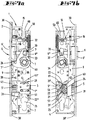
- the lock preferably has an anti-panic function, in which not only a latch 6 but also a bolt 5 can be retracted by actuating a nut 7, so that a door equipped with such a lock can be opened simply by actuating the handle.
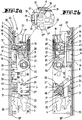
- the lock is in a structure according to Figures 1a to 5b is constructed as a self-locking lock, it also has the function that when a door equipped with the lock is closed, it automatically enters a locked position, that is, the bolt 5 moves forward from a closed position into a pre-locked position. The force required for this is stored in an energy storage device 10.
- the lock shown has a housing 1 which is formed by a forend 2, a lock base 3 and a lock cover 4.
- a bolt 5 with a bolt head 5 'and a bolt tail 5 "and a latch 6 with a latch head 6' and a latch tail 6" are mounted between the lock bottom 3 and the lock cover 4.
- the latch 6 can be withdrawn with a socket 7, which is likewise mounted between the lock bottom 3 and the lock cover 4 and which can move an arm support 40 with a socket arm.
- a first nut arm 7 'attached to the arm carrier 40 engages the latch tail 6 ′′.
- a transfer slide 33 is coupled to a nut spring 32 which engages a transfer projection 34 of the nut 7 in order to reset the nut after rotation.
- a second socket arm 7 ′′ engages a driver 26 of a main slide 8 in order to move the main slide 8 from a tumbler function position into an open position.
- a tumbler projection 28 of the first main slide 8 engages in a bearing opening 29 of the bolt tail 5 ′′ ( Figure 4a ).
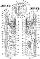
- a release element 17 is provided.
- the release element 17 is in the form of a two-armed lever. At the end of a first lever arm there is a locking lug 18 which engages under a locking step 19 of the main slide 8. In addition to the locking step 19, further locking steps 42 are arranged in the manner of a tooth.
- the second arm of the release element 17 forms an actuating arm 48 which can be acted upon by an actuating shoulder 41 of the latch tail 6 ′′ when the latch 6 is in a completely pre-closed position ( Figure 4b ) takes.
- a spring element 49 is provided which rests in an arcuate recess of the release element 17, which is designed as a flat piece, and which is supported on a support shoulder of a bearing body 11.
- the bearing body 11 has fastening projections 69, 69 ′ on two sides pointing away from one another, which can be inserted into fastening openings 70, 70 ′ in the lock bottom 3 and lock cover 4.
- a bearing axis 47 of the release element 17 is mounted in a bearing bore 59 of the bearing body 11, which consists of plastic and is held between the lock cover 4 and lock base 3.
- a latching body 12 which has the shape of a round pin with a head 12 'with an enlarged diameter.
- the end of the latching body 12 facing away from the head forms a latching projection 12 "which, in a blocking position ( figure 1a ) lies in the path of movement of a latch tail 6 ′′.
- a spring element 35 In the bearing opening 29 there is also a spring element 35, through which the shaft of the latching body 12 extends.
- the spring element 35 is supported on a step of the bearing opening 29 and supports the head 12 ' in its blocking position on a control surface 37 of the control latch 13.
- control slope 36 on which the head 12 'can slide when the control latch 13 is from an actuated position ( Figure 2a ) to a non-actuated position ( Figure 1a ) is relocated.
- a clamping ring 39 is seated on the shaft of the locking body 12, which locks the locking body 12 in the bearing opening 29.
- the bearing axis 47 of the release element 17 is tied to the bearing body 11 with a similar clamping ring.
- the energy store 10, which acts on the main slide 8, is also a detachable structural unit. From a bearing block 45, two fastening projections 45 ′ protrude, which protrude into fastening openings 44 in the lock bottom 3 and lock cover 4.
- a bearing pin 46 which carries a helical compression spring 58, protrudes from the bearing block 45.
- the helical compression spring 58 is supported on one side on the bearing block 45 and on the other side on a driver 27 of the main slide 8. For this purpose, the bearing pin 46 passes through a bore in the driver 27.
- the locking projection 12 ′′ emerges from the path of movement of the latch tail 6 ′′. If trap 6 falls, as in the Figure 3a shown, in the latch entry opening 56 assigned to it, the latch head 6 ′′ can pass the latching projection 12 ′′.
- the linear movement of the first main slide 8 is transmitted via a transmission gear 21 to a crank arrangement with which the bolt 5 is shifted into the closed position.
- the body forming the transmission gear 21 and its circumferential toothing 21 ′ has a crank arm 63 and a toothing 66 which engages in a counter-toothing 65 of the bolt 5.
- the Figures 7a to 8b show the lock according to the invention in a construction as a non-self-locking anti-panic lock.
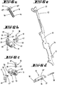
- the energy store 10 (cf. Figure 6a ), the bearing body 11 (cf. Figure 6b ), tax trap 13 (cf. Figure 6d ) and the second main slide 9 (cf. Figure 6e ) have been removed.
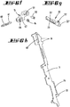
- a retaining member carrier 15 (cf. Figure 6f ), a drive slide 22 (cf. Figure 6g ) and the first main slide 8 (cf. Figure 6h ) has been used instead of the second main slide 9.
- the holding member carrier 15 is a plastic part which is supported on a projection in the lock housing with a helical spring 60 seated on a pin 61. The other end of the helical gear spring 60 engages one end of the holding member carrier 15.
- the holding member carrier 15 has a pin 67 which carries an annular holding member 14. An elongated hole 51, which acts as a bearing eye, is penetrated by a bearing pin 52, which also penetrates an elongated hole 62 of the second main slide 9.
- the first main slide 8 has two locking flanks 16 which form a V-shaped locking niche.
- the retaining member 14 can engage in this locking niche in order to move the first main slide 8 in an open position ( Figure 7b ) to keep.
- the holding member carrier 15 also has two holding projections 64 pointing away from one another, which engage in fastening openings 68 in the lock base 3 and lock cover 4 in order to tie the holding member carrier 15 in the lock housing.
- the fastening openings 68 are elongated holes in which the fastening projection 64 can move.
- the lock base 3 and lock cover 4 also have a guide slot 53 in the area of the lock cylinder insertion opening 25, which runs obliquely to the direction of displacement of the second main slide 9, i.e. also obliquely to the faceplate 2.
- this guide slot 3 there is a respective guide pin 57 in the Figure 6g illustrated drive slide 22.
- the drive slide 22 has a straight back 22 'and a linear toothing 23 opposite the back 22'.
- the slot 53 can also be arcuate and the toothing 23 can also be arcuate.
- the toothing 23 meshes with the circumferential toothing 21 'of the transmission gear 21. Since the circumferential toothing 21' also meshes with the toothing 24 of the first main slide 8, a displacement of the drive slide 2 is transmitted directly to the second main slide 9 with a reversal of movement.
- the first main slide 8 can thus be shifted into an open position by engagement of the locking element of the locking cylinder on the driver 31 or shifted from the open position into the tumbler function position by engagement of the locking element on the nose 22 ′′.
- the holding member 14 forms a locking pin which engages in a locking niche which is formed by the two locking flanks 16.
- the locking niche is formed by two essentially rectilinear locking flanks 16 which are at an angle of greater than 90 ° to one another.
- the locking niche opens in a direction pointing away from the faceplate 2.
- the lock is opened in the manner described above, either by turning the handle follower 7, by externally acting on the button 43 and the bolt 5 or by actuating a lock cylinder.
- a lock which is characterized in that the lock is activated by adding at least one energy store 10 engaging the main slide 8, 9, a latching element 12 holding the latch 6 in an incompletely pre-locked position, a control latch 13, which in an actuated position for the latching element 12 Releases shifting into a release position in which the latch 6 extends from its incompletely pre-locked position to a fully pre-locked position, a release element 17 holding the main slide 8, 9 in the open position, which is released by the latch 6 when it is moved from the incompletely pre-locked position in the completely pre-closed position is brought from a detent position into a release position, can be changed to a self-locking lock, in which the relaxing energy store 10 moves the main slide 8, 9 into its open position.
- a lock which is characterized by a holding member 14 which is fastened in the housing 1 and which cooperates with a counter holding member 16 of the main slide 9 in order to hold the main slide 9 in the second position, the holding member 14 and the counter holding member 16 being displaced by overcoming a latching force of the main slide 9 can be separated from one another in the first position.
- a lock which is characterized by a drive slide 22 which has a straight toothing and which meshes with a circumferential toothing 21 'of a transmission gear 21, a displacement of the drive slide 22 causing a rotation of the transmission gear 21 and a displacement of the bolt 5 and the main slide 9 derived therefrom .
- a lock which is characterized in that the release element 17 is a pivot lever which, in its latching position, engages under a latching step 19 of the main slide 8 with a latching lug 18 and is brought into the release position by an actuating shoulder 41 of the latch 6.
- a lock which is characterized in that the latching element 12 is a latching body 12 which is mounted in a bearing opening 29 of a bearing body 11 fastened to the housing 1 and can be displaced parallel to the direction of displacement of the main slide 8.
- a lock which is characterized in that the lock bottom 3 and lock cover 4 each have a fastening opening 44 into which fastening projections 45 'of a bearing block 45 formed by the energy store 10 and releasably fastened to the housing 1 engage.
- a lock which is characterized in that the bearing block 45 carries a compression spring 58 which is supported on a driver 27 of the main slide 8, which has an opening through which a bearing pin 46 attached to the bearing block 45 protrudes, which extends through the compression spring.
- a lock which is characterized in that the latching element 12 is a bearing body 11 which is mounted in a bearing opening 29 of a bearing body 11 detachably fastened to the housing 1 and can be displaced parallel to the direction of displacement of the main slide 8 Is latching body, it being provided in particular that the bearing body 11 is an insert piece made of plastic, which is held between the lock base 3 and lock cover 4.
- a lock which is characterized in that the latching element 12 is a pin having a head 12 'and a latching projection 12 "which is acted upon by a spring element 35 in the direction of a support surface 37 of the control latch 13.
- a lock which is characterized in that the support surface 37 is adjoined by a control slope 36 which, when the control latch 13 is displaced forward, acts on the head 12 'in order to displace the latching body 12 from its release position into its blocking position which inhibits the complete forward displacement of the latch 6 .
- a lock which is characterized in that the compression spring 35 acting on the head 12 ′ of the latching element 12 is supported on a step of the bearing opening 29.
- a lock which is characterized in that, to change the lock to a self-locking lock, a first main slide 8 is exchanged for a second main slide 9 and / or that the energy store 10, a bearing body 11 for mounting the latching element 12 and the release element 17 through in Openings 44, 70, 70 'engaging projections 45', 69, 69 'are releasably attached to the housing 1 and / or that all components to be supplemented or exchanged for changing the lock to a self-locking lock can be removed by form-fitting engagement means 69, 69', 45 ' , 67, 70, 70 'are connected to the housing 1.
- a lock which is characterized in that the release element 17 is a pivot lever which, in its latching position, engages under a latching step 19 of the main slide 8 with a latching lug 18 and is brought into the release position by an actuating shoulder 41 of the latch 6.
- a lock which is characterized in that the release element 17 has an actuating arm 48 which is acted upon by an actuating shoulder 41 of the latch tail 6 ′′.
- a lock which is characterized in that the release element 17 is acted upon by a spring element 49 in a position engaging under the latching step 19 of the main slide 9.
- a lock which is characterized in that one or more teeth 42 acting as auxiliary locking steps are adjacent to the locking step 19.
- a lock which is characterized in that the bearing body 11 forms a bearing bore 59 for mounting the bearing axis 47 of the release element and / or two bearing bores 29, 59 arranged perpendicularly and offset from one another and / or a support shoulder for a spring element 49 acting on the release element 17.
- a lock which is characterized by a holding member 14 which is fastened in the housing 1 and which cooperates with a counter holding member 16 of the main slide 9 in order to hold the main slide 9 in the second position, the holding member 14 and the counter holding member 16 being displaced by overcoming a latching force of the main slide 9 can be separated from one another in the first position.
- a lock which is characterized in that the holding member 14 is a locking pin which can be displaced in the direction transverse to the direction of displacement of the main slide 9 against the restoring force of a spring element 60 and which, in the release position of the main slide 9, rests in a locking niche formed by the counter-holding member 16.
- a lock which is characterized in that the locking niche is formed by two inclined surfaces.
- a lock which is characterized in that the holding member 14 is seated on a holding member carrier 15 which can be displaced between the lock base 3 and the lock cover 4 in the direction transverse to the direction of displacement of the main slide 9.
- a lock which is characterized in that the spring element 60 is supported on a bracket 50 held between the lock bottom 3 and the lock cover 4, and / or that the holding member carrier 15, the spring element 60 and a bracket 50 that abuts the spring element 60 can only be detached by in Fastening openings of the lock cover 44 and the lock base 3 plugging retaining projections 64 are fixed in the housing 1 and / or that an elongated bearing eye 51 of the retaining member carrier 15 is penetrated by a bearing pin 52, which bearing pin 52 also extends through an elongated hole 62 of the main slide 9 and / or that the Retaining member carrier 15 is a plastic injection molded part.
- a lock which is characterized in that a drive slide 22 meshing with a circumferential toothing 21 'of a transmission gear 21 is detachable in an oblique direction to the displacement direction of the main slide 8, 9 extending guide slot 53 of the lock bottom 3 and / or the lock cover 4 is guided.
- a lock which is characterized in that the transmission gear 21 engages in a linear toothing 24 of the main slide 8, 9 and / or that the drive slide 22 has a straight back 22 'which is supported on a support pin 54 fixed to the housing and / or that the Drive slide 22 has a nose 22 ′′ which can be acted upon by the locking member of a lock cylinder.
- a lock which is characterized in that the transmission gear 21 has a crank arm 63 and / or a toothing 26 in order to displace the bolt 5 in a direction transverse to the displacement direction of the main slide 8, 9.
- a lock which is characterized in that the first position of the main slide 8, 9 is a tumbler function position preventing a displacement of the bolt 5 and / or that the second position of the main slide 8, 9 is an open position in which a door having the lock passes through only a retraction of the trap 6 can be opened.
- the invention also relates to design forms in which some of the features mentioned in the above description are not implemented, in particular insofar as they are recognizable for the respective purpose or can be replaced by other technically equivalent means.
- ⁇ b> ⁇ u> List of reference symbols ⁇ /u> ⁇ /b> 1 casing 19th Rest step 2 Faceplate 20th Spring element 3 Castle floor 21 Transmission gear 4th Castle ceiling 21 ' Circumferential gearing 5 bars 22nd Drive slide 5 ' Bolt head 22 ' move 5 " Bolt tail 22 " nose 6th Cases 23 Linear toothing 6 ' Trap head 24 Linear toothing 6 " Trap tail 25th Closing link insertion opening 7th nut 26th Carrier 7 ' first nut arm 27 Carrier 7 " second nut arm 28 Guard locking projection 8th first main slide 29 Warehouse opening 9 second main slide 30th Connecting rod 10 Energy storage 30 ' Connecting rod 11 Bearing body 31 Carrier 12th Locking body 32 Nut feather 12 ' head 33 Transfer slide 12 " Locking projection 34 Transfer lead 13th Tax trap 35 Spring element 13
Landscapes
- Engineering & Computer Science (AREA)
- Structural Engineering (AREA)
- Business, Economics & Management (AREA)
- Emergency Management (AREA)
- Lock And Its Accessories (AREA)
Applications Claiming Priority (1)
| Application Number | Priority Date | Filing Date | Title |
|---|---|---|---|
| DE102019125144.3A DE102019125144A1 (de) | 2019-09-18 | 2019-09-18 | Modular aufgebautes Schloss mit Antipanik-Funktion |
Publications (4)
| Publication Number | Publication Date |
|---|---|
| EP3805493A2 true EP3805493A2 (fr) | 2021-04-14 |
| EP3805493A3 EP3805493A3 (fr) | 2021-07-14 |
| EP3805493C0 EP3805493C0 (fr) | 2023-08-09 |
| EP3805493B1 EP3805493B1 (fr) | 2023-08-09 |
Family
ID=72474232
Family Applications (1)
| Application Number | Title | Priority Date | Filing Date |
|---|---|---|---|
| EP20195952.5A Active EP3805493B1 (fr) | 2019-09-18 | 2020-09-14 | Serrure modulaire à fonction anti-panique |
Country Status (3)
| Country | Link |
|---|---|
| EP (1) | EP3805493B1 (fr) |
| DE (1) | DE102019125144A1 (fr) |
| PL (1) | PL3805493T3 (fr) |
Families Citing this family (2)
| Publication number | Priority date | Publication date | Assignee | Title |
|---|---|---|---|---|
| DE102021109071A1 (de) | 2021-04-12 | 2022-10-13 | WILKA Schließtechnik GmbH | Elektrischer Öffner für einen Türverschluss |
| DE102021118229A1 (de) | 2021-07-14 | 2023-01-19 | WILKA Schließtechnik GmbH | Schloss mit in einer zurückgezogenen Stellung fixierbaren Falle |
Citations (3)
| Publication number | Priority date | Publication date | Assignee | Title |
|---|---|---|---|---|
| DE19905597C2 (de) | 1999-02-11 | 2002-07-18 | Wilka Schliestechnik Gmbh | Panikschloß |
| DE102004013646A1 (de) | 2004-03-12 | 2005-09-29 | Wilka Schließtechnik GmbH | Panikschloss |
| DE102012111526A1 (de) | 2012-11-28 | 2014-05-28 | Wilka Schließtechnik GmbH | Rohrrahmenschloss mit Panikfunktion |
Family Cites Families (6)
| Publication number | Priority date | Publication date | Assignee | Title |
|---|---|---|---|---|
| IT1284465B1 (it) * | 1996-07-04 | 1998-05-21 | Welka Serrature Spa | Serratura per una porta e simili |
| CH694970A5 (de) * | 2000-04-19 | 2005-10-14 | Glutz Ag | Wahlweise bedienbares Türschloss. |
| BE1020811A3 (nl) * | 2012-05-07 | 2014-05-06 | Parys Remi E Van | Paniekslot. |
| EP3045623B1 (fr) * | 2015-01-19 | 2020-02-19 | ASSA ABLOY (Schweiz) AG | Dispositif de sécurisation de porte |
| DE102016118119A1 (de) * | 2016-09-26 | 2018-03-29 | Assa Abloy (Schweiz) Ag | Modulares Schloss |
| AT16382U1 (de) * | 2017-11-08 | 2019-08-15 | Roto Frank Ag | Schloss |
-
2019
- 2019-09-18 DE DE102019125144.3A patent/DE102019125144A1/de active Pending
-
2020
- 2020-09-14 PL PL20195952.5T patent/PL3805493T3/pl unknown
- 2020-09-14 EP EP20195952.5A patent/EP3805493B1/fr active Active
Patent Citations (3)
| Publication number | Priority date | Publication date | Assignee | Title |
|---|---|---|---|---|
| DE19905597C2 (de) | 1999-02-11 | 2002-07-18 | Wilka Schliestechnik Gmbh | Panikschloß |
| DE102004013646A1 (de) | 2004-03-12 | 2005-09-29 | Wilka Schließtechnik GmbH | Panikschloss |
| DE102012111526A1 (de) | 2012-11-28 | 2014-05-28 | Wilka Schließtechnik GmbH | Rohrrahmenschloss mit Panikfunktion |
Also Published As
| Publication number | Publication date |
|---|---|
| EP3805493A3 (fr) | 2021-07-14 |
| EP3805493C0 (fr) | 2023-08-09 |
| PL3805493T3 (pl) | 2024-03-11 |
| EP3805493B1 (fr) | 2023-08-09 |
| DE102019125144A1 (de) | 2021-03-18 |
Similar Documents
| Publication | Publication Date | Title |
|---|---|---|
| EP1932989B1 (fr) | Système de fermeture pour portes, fenêtres ou analogues, en particulier crémone-serrure à fonction d'urgence et de verrouillage à plusieurs points | |
| DE69423084T2 (de) | Schloss und Schlossvorrichtung für eine Tür oder ein fenster | |
| DE4324300C2 (de) | Antipanik-Türschloß | |
| DE102006011263B4 (de) | Verriegelungssystem für eine Tür | |
| DE202013000921U1 (de) | Panikschloss | |
| EP1574644A2 (fr) | Système de verrouillage pour portes, fenêtres ou similaires, notamment crémone-serrure avec fonction anti-panique et avec plusieurs points de condamnation | |
| EP3805493A2 (fr) | Serrure modulaire à fonction anti-panique | |
| EP0653535B1 (fr) | Serrure | |
| EP2562335B1 (fr) | Serrure automatique | |
| DE4114007C2 (de) | Treibstangenverschluß | |
| DE102012111881A1 (de) | Motorisch betreibbares Standflügelschloss mit Riegel- und Fallenauswerfer | |
| DE102015000606A1 (de) | Verriegelungsvorrichtung für einen schwenkbar gelagerten Flügel | |
| DE102012111526B4 (de) | Rohrrahmenschloss mit Panikfunktion | |
| EP2339096A2 (fr) | Serrure à crémone dotée d'une fonction anti-panique et d'un verrouillage multiple | |
| DE19653611B4 (de) | Schloß mit Riegel und Falle | |
| DE3931101A1 (de) | Automatisch verriegelndes schloss | |
| EP1672153B1 (fr) | Serrure avec pêne dormant et dispositif de commande du pêne dormant | |
| EP3628801A1 (fr) | Dispositif de fermeture pour une porte | |
| EP3907357A1 (fr) | Dispositif de verrouillage | |
| DE102013111467A1 (de) | Multischloss | |
| EP0974721B1 (fr) | Serrure à plusieurs pênes | |
| EP0853177B1 (fr) | Serrure avec pênes demi-tour et dormant, opéré par cléf ou par fouillot-bequille | |
| DE202010006285U1 (de) | Einsteckschloss | |
| DE102021118229A1 (de) | Schloss mit in einer zurückgezogenen Stellung fixierbaren Falle | |
| EP1455041B1 (fr) | Serrure à plusieurs pênes avec une tringle et un dispositif de retenue. |
Legal Events
| Date | Code | Title | Description |
|---|---|---|---|
| PUAI | Public reference made under article 153(3) epc to a published international application that has entered the european phase |
Free format text: ORIGINAL CODE: 0009012 |
|
| STAA | Information on the status of an ep patent application or granted ep patent |
Free format text: STATUS: THE APPLICATION HAS BEEN PUBLISHED |
|
| AK | Designated contracting states |
Kind code of ref document: A2 Designated state(s): AL AT BE BG CH CY CZ DE DK EE ES FI FR GB GR HR HU IE IS IT LI LT LU LV MC MK MT NL NO PL PT RO RS SE SI SK SM TR |
|
| AX | Request for extension of the european patent |
Extension state: BA ME |
|
| PUAL | Search report despatched |
Free format text: ORIGINAL CODE: 0009013 |
|
| AK | Designated contracting states |
Kind code of ref document: A3 Designated state(s): AL AT BE BG CH CY CZ DE DK EE ES FI FR GB GR HR HU IE IS IT LI LT LU LV MC MK MT NL NO PL PT RO RS SE SI SK SM TR |
|
| RIC1 | Information provided on ipc code assigned before grant |
Ipc: E05B 59/00 20060101AFI20210604BHEP Ipc: E05B 63/20 20060101ALI20210604BHEP Ipc: E05B 65/10 20060101ALI20210604BHEP |
|
| STAA | Information on the status of an ep patent application or granted ep patent |
Free format text: STATUS: REQUEST FOR EXAMINATION WAS MADE |
|
| 17P | Request for examination filed |
Effective date: 20211221 |
|
| RBV | Designated contracting states (corrected) |
Designated state(s): AL AT BE BG CH CY CZ DE DK EE ES FI FR GB GR HR HU IE IS IT LI LT LU LV MC MK MT NL NO PL PT RO RS SE SI SK SM TR |
|
| GRAP | Despatch of communication of intention to grant a patent |
Free format text: ORIGINAL CODE: EPIDOSNIGR1 |
|
| STAA | Information on the status of an ep patent application or granted ep patent |
Free format text: STATUS: GRANT OF PATENT IS INTENDED |
|
| INTG | Intention to grant announced |
Effective date: 20220513 |
|
| RIN1 | Information on inventor provided before grant (corrected) |
Inventor name: BLECKMANN, JOERG Inventor name: HEUER, STEFAN |
|
| GRAJ | Information related to disapproval of communication of intention to grant by the applicant or resumption of examination proceedings by the epo deleted |
Free format text: ORIGINAL CODE: EPIDOSDIGR1 |
|
| STAA | Information on the status of an ep patent application or granted ep patent |
Free format text: STATUS: REQUEST FOR EXAMINATION WAS MADE |
|
| INTC | Intention to grant announced (deleted) | ||
| GRAP | Despatch of communication of intention to grant a patent |
Free format text: ORIGINAL CODE: EPIDOSNIGR1 |
|
| STAA | Information on the status of an ep patent application or granted ep patent |
Free format text: STATUS: GRANT OF PATENT IS INTENDED |
|
| INTG | Intention to grant announced |
Effective date: 20230105 |
|
| GRAS | Grant fee paid |
Free format text: ORIGINAL CODE: EPIDOSNIGR3 |
|
| GRAA | (expected) grant |
Free format text: ORIGINAL CODE: 0009210 |
|
| STAA | Information on the status of an ep patent application or granted ep patent |
Free format text: STATUS: THE PATENT HAS BEEN GRANTED |
|
| APBM | Appeal reference recorded |
Free format text: ORIGINAL CODE: EPIDOSNREFNO |
|
| PUAC | Information related to the publication of a b1 document modified or deleted |
Free format text: ORIGINAL CODE: 0009299EPPU |
|
| STAA | Information on the status of an ep patent application or granted ep patent |
Free format text: STATUS: GRANT OF PATENT IS INTENDED |
|
| AK | Designated contracting states |
Kind code of ref document: B1 Designated state(s): AL AT BE BG CH CY CZ DE DK EE ES FI FR GB GR HR HU IE IS IT LI LT LU LV MC MK MT NL NO PL PT RO RS SE SI SK SM TR |
|
| REG | Reference to a national code |
Ref country code: GB Ref legal event code: FG4D Free format text: NOT ENGLISH |
|
| REG | Reference to a national code |
Ref country code: AT Ref legal event code: REF Ref document number: 1566825 Country of ref document: AT Kind code of ref document: T Effective date: 20230515 |
|
| REG | Reference to a national code |
Ref country code: DE Ref legal event code: R096 Ref document number: 502020003232 Country of ref document: DE |
|
| DB1 | Publication of patent cancelled |
Effective date: 20230428 |
|
| REG | Reference to a national code |
Ref country code: IE Ref legal event code: FG4D Free format text: LANGUAGE OF EP DOCUMENT: GERMAN Ref country code: DE Ref legal event code: R107 Ref document number: 502020003232 Country of ref document: DE |
|
| APAF | Appeal reference modified |
Free format text: ORIGINAL CODE: EPIDOSCREFNE |
|
| GRAA | (expected) grant |
Free format text: ORIGINAL CODE: 0009210 |
|
| STAA | Information on the status of an ep patent application or granted ep patent |
Free format text: STATUS: THE PATENT HAS BEEN GRANTED |
|
| REG | Reference to a national code |
Ref country code: AT Ref legal event code: REZ Ref document number: 1566825 Country of ref document: AT Kind code of ref document: T Effective date: 20230510 |
|
| AK | Designated contracting states |
Kind code of ref document: B1 Designated state(s): AL AT BE BG CH CY CZ DE DK EE ES FI FR GB GR HR HU IE IS IT LI LT LU LV MC MK MT NL NO PL PT RO RS SE SI SK SM TR |
|
| REG | Reference to a national code |
Ref country code: CH Ref legal event code: EP |
|
| REG | Reference to a national code |
Ref country code: DE Ref legal event code: R096 Ref document number: 502020003232 Country of ref document: DE |
|
| U01 | Request for unitary effect filed |
Effective date: 20230818 |
|
| U07 | Unitary effect registered |
Designated state(s): AT BE BG DE DK EE FI FR IT LT LU LV MT NL PT SE SI Effective date: 20230824 |
|
| U20 | Renewal fee for the european patent with unitary effect paid |
Year of fee payment: 4 Effective date: 20230905 |
|
| PG25 | Lapsed in a contracting state [announced via postgrant information from national office to epo] |
Ref country code: NO Free format text: LAPSE BECAUSE OF FAILURE TO SUBMIT A TRANSLATION OF THE DESCRIPTION OR TO PAY THE FEE WITHIN THE PRESCRIBED TIME-LIMIT Effective date: 20230810 |
|
| PG25 | Lapsed in a contracting state [announced via postgrant information from national office to epo] |
Ref country code: IS Free format text: LAPSE BECAUSE OF FAILURE TO SUBMIT A TRANSLATION OF THE DESCRIPTION OR TO PAY THE FEE WITHIN THE PRESCRIBED TIME-LIMIT Effective date: 20230910 Ref country code: GR Free format text: LAPSE BECAUSE OF FAILURE TO SUBMIT A TRANSLATION OF THE DESCRIPTION OR TO PAY THE FEE WITHIN THE PRESCRIBED TIME-LIMIT Effective date: 20230811 |
|
| PG25 | Lapsed in a contracting state [announced via postgrant information from national office to epo] |
Ref country code: RS Free format text: LAPSE BECAUSE OF FAILURE TO SUBMIT A TRANSLATION OF THE DESCRIPTION OR TO PAY THE FEE WITHIN THE PRESCRIBED TIME-LIMIT Effective date: 20230809 Ref country code: NO Free format text: LAPSE BECAUSE OF FAILURE TO SUBMIT A TRANSLATION OF THE DESCRIPTION OR TO PAY THE FEE WITHIN THE PRESCRIBED TIME-LIMIT Effective date: 20231109 Ref country code: HR Free format text: LAPSE BECAUSE OF FAILURE TO SUBMIT A TRANSLATION OF THE DESCRIPTION OR TO PAY THE FEE WITHIN THE PRESCRIBED TIME-LIMIT Effective date: 20230809 |
|
| PG25 | Lapsed in a contracting state [announced via postgrant information from national office to epo] |
Ref country code: ES Free format text: LAPSE BECAUSE OF FAILURE TO SUBMIT A TRANSLATION OF THE DESCRIPTION OR TO PAY THE FEE WITHIN THE PRESCRIBED TIME-LIMIT Effective date: 20230809 |
|
| PG25 | Lapsed in a contracting state [announced via postgrant information from national office to epo] |
Ref country code: SM Free format text: LAPSE BECAUSE OF FAILURE TO SUBMIT A TRANSLATION OF THE DESCRIPTION OR TO PAY THE FEE WITHIN THE PRESCRIBED TIME-LIMIT Effective date: 20230809 Ref country code: ES Free format text: LAPSE BECAUSE OF FAILURE TO SUBMIT A TRANSLATION OF THE DESCRIPTION OR TO PAY THE FEE WITHIN THE PRESCRIBED TIME-LIMIT Effective date: 20230809 Ref country code: CZ Free format text: LAPSE BECAUSE OF FAILURE TO SUBMIT A TRANSLATION OF THE DESCRIPTION OR TO PAY THE FEE WITHIN THE PRESCRIBED TIME-LIMIT Effective date: 20230809 Ref country code: SK Free format text: LAPSE BECAUSE OF FAILURE TO SUBMIT A TRANSLATION OF THE DESCRIPTION OR TO PAY THE FEE WITHIN THE PRESCRIBED TIME-LIMIT Effective date: 20230809 |
|
| REG | Reference to a national code |
Ref country code: DE Ref legal event code: R097 Ref document number: 502020003232 Country of ref document: DE |
|
| PG25 | Lapsed in a contracting state [announced via postgrant information from national office to epo] |
Ref country code: MC Free format text: LAPSE BECAUSE OF FAILURE TO SUBMIT A TRANSLATION OF THE DESCRIPTION OR TO PAY THE FEE WITHIN THE PRESCRIBED TIME-LIMIT Effective date: 20230809 |
|
| PLBE | No opposition filed within time limit |
Free format text: ORIGINAL CODE: 0009261 |
|
| STAA | Information on the status of an ep patent application or granted ep patent |
Free format text: STATUS: NO OPPOSITION FILED WITHIN TIME LIMIT |
|
| REG | Reference to a national code |
Ref country code: IE Ref legal event code: MM4A |
|
| PG25 | Lapsed in a contracting state [announced via postgrant information from national office to epo] |
Ref country code: IE Free format text: LAPSE BECAUSE OF NON-PAYMENT OF DUE FEES Effective date: 20230914 |
|
| 26N | No opposition filed |
Effective date: 20240513 |
|
| PG25 | Lapsed in a contracting state [announced via postgrant information from national office to epo] |
Ref country code: IE Free format text: LAPSE BECAUSE OF NON-PAYMENT OF DUE FEES Effective date: 20230914 |
|
| U20 | Renewal fee for the european patent with unitary effect paid |
Year of fee payment: 5 Effective date: 20240911 |
|
| PG25 | Lapsed in a contracting state [announced via postgrant information from national office to epo] |
Ref country code: RO Free format text: LAPSE BECAUSE OF FAILURE TO SUBMIT A TRANSLATION OF THE DESCRIPTION OR TO PAY THE FEE WITHIN THE PRESCRIBED TIME-LIMIT Effective date: 20230809 |
|
| PG25 | Lapsed in a contracting state [announced via postgrant information from national office to epo] |
Ref country code: RO Free format text: LAPSE BECAUSE OF FAILURE TO SUBMIT A TRANSLATION OF THE DESCRIPTION OR TO PAY THE FEE WITHIN THE PRESCRIBED TIME-LIMIT Effective date: 20230809 |
|
| GBPC | Gb: european patent ceased through non-payment of renewal fee |
Effective date: 20240914 |
|
| PG25 | Lapsed in a contracting state [announced via postgrant information from national office to epo] |
Ref country code: GB Free format text: LAPSE BECAUSE OF NON-PAYMENT OF DUE FEES Effective date: 20240914 |
|
| PG25 | Lapsed in a contracting state [announced via postgrant information from national office to epo] |
Ref country code: CY Free format text: LAPSE BECAUSE OF FAILURE TO SUBMIT A TRANSLATION OF THE DESCRIPTION OR TO PAY THE FEE WITHIN THE PRESCRIBED TIME-LIMIT; INVALID AB INITIO Effective date: 20200914 |
|
| PG25 | Lapsed in a contracting state [announced via postgrant information from national office to epo] |
Ref country code: HU Free format text: LAPSE BECAUSE OF FAILURE TO SUBMIT A TRANSLATION OF THE DESCRIPTION OR TO PAY THE FEE WITHIN THE PRESCRIBED TIME-LIMIT; INVALID AB INITIO Effective date: 20200914 |
|
| REG | Reference to a national code |
Ref country code: CH Ref legal event code: U11 Free format text: ST27 STATUS EVENT CODE: U-0-0-U10-U11 (AS PROVIDED BY THE NATIONAL OFFICE) Effective date: 20251001 |
|
| PGFP | Annual fee paid to national office [announced via postgrant information from national office to epo] |
Ref country code: PL Payment date: 20250818 Year of fee payment: 6 |
|
| U20 | Renewal fee for the european patent with unitary effect paid |
Year of fee payment: 6 Effective date: 20250911 |
|
| PG25 | Lapsed in a contracting state [announced via postgrant information from national office to epo] |
Ref country code: TR Free format text: LAPSE BECAUSE OF FAILURE TO SUBMIT A TRANSLATION OF THE DESCRIPTION OR TO PAY THE FEE WITHIN THE PRESCRIBED TIME-LIMIT Effective date: 20230809 |
|
| PGFP | Annual fee paid to national office [announced via postgrant information from national office to epo] |
Ref country code: CH Payment date: 20251001 Year of fee payment: 6 |