EP3805576A2 - Couplage - Google Patents
Couplage Download PDFInfo
- Publication number
- EP3805576A2 EP3805576A2 EP20197724.6A EP20197724A EP3805576A2 EP 3805576 A2 EP3805576 A2 EP 3805576A2 EP 20197724 A EP20197724 A EP 20197724A EP 3805576 A2 EP3805576 A2 EP 3805576A2
- Authority
- EP
- European Patent Office
- Prior art keywords
- coupling
- column
- pivot bearing
- traverse
- coupling part
- Prior art date
- Legal status (The legal status is an assumption and is not a legal conclusion. Google has not performed a legal analysis and makes no representation as to the accuracy of the status listed.)
- Withdrawn
Links
- 230000008878 coupling Effects 0.000 title claims abstract description 310
- 238000010168 coupling process Methods 0.000 title claims abstract description 310
- 238000005859 coupling reaction Methods 0.000 title claims abstract description 310
- 230000007246 mechanism Effects 0.000 claims description 23
- 238000007373 indentation Methods 0.000 claims description 21
- 238000003780 insertion Methods 0.000 description 10
- 230000037431 insertion Effects 0.000 description 10
- 230000005484 gravity Effects 0.000 description 9
- 102000004315 Forkhead Transcription Factors Human genes 0.000 description 8
- 108090000852 Forkhead Transcription Factors Proteins 0.000 description 8
- 238000010276 construction Methods 0.000 description 6
- 230000002401 inhibitory effect Effects 0.000 description 5
- 239000000463 material Substances 0.000 description 5
- 230000002829 reductive effect Effects 0.000 description 5
- 229910052751 metal Inorganic materials 0.000 description 4
- 239000002184 metal Substances 0.000 description 4
- 239000004033 plastic Substances 0.000 description 4
- 230000008901 benefit Effects 0.000 description 3
- 210000003128 head Anatomy 0.000 description 3
- 230000036961 partial effect Effects 0.000 description 3
- 229910000831 Steel Inorganic materials 0.000 description 2
- 229910052782 aluminium Inorganic materials 0.000 description 2
- XAGFODPZIPBFFR-UHFFFAOYSA-N aluminium Chemical compound [Al] XAGFODPZIPBFFR-UHFFFAOYSA-N 0.000 description 2
- 239000011324 bead Substances 0.000 description 2
- 230000001419 dependent effect Effects 0.000 description 2
- 239000010959 steel Substances 0.000 description 2
- 230000002195 synergetic effect Effects 0.000 description 2
- 206010047571 Visual impairment Diseases 0.000 description 1
- 238000004873 anchoring Methods 0.000 description 1
- 230000015572 biosynthetic process Effects 0.000 description 1
- 230000008859 change Effects 0.000 description 1
- 230000002950 deficient Effects 0.000 description 1
- 238000011161 development Methods 0.000 description 1
- 230000018109 developmental process Effects 0.000 description 1
- 238000006073 displacement reaction Methods 0.000 description 1
- 238000005553 drilling Methods 0.000 description 1
- 230000000694 effects Effects 0.000 description 1
- 238000005516 engineering process Methods 0.000 description 1
- 238000009434 installation Methods 0.000 description 1
- 210000001331 nose Anatomy 0.000 description 1
- 230000003287 optical effect Effects 0.000 description 1
- 230000036316 preload Effects 0.000 description 1
- 230000008439 repair process Effects 0.000 description 1
- 230000002441 reversible effect Effects 0.000 description 1
- 239000007787 solid Substances 0.000 description 1
- 239000000725 suspension Substances 0.000 description 1
- 238000011144 upstream manufacturing Methods 0.000 description 1
- 208000029257 vision disease Diseases 0.000 description 1
- 230000004393 visual impairment Effects 0.000 description 1
Images



Classifications
-
- F—MECHANICAL ENGINEERING; LIGHTING; HEATING; WEAPONS; BLASTING
- F16—ENGINEERING ELEMENTS AND UNITS; GENERAL MEASURES FOR PRODUCING AND MAINTAINING EFFECTIVE FUNCTIONING OF MACHINES OR INSTALLATIONS; THERMAL INSULATION IN GENERAL
- F16M—FRAMES, CASINGS OR BEDS OF ENGINES, MACHINES OR APPARATUS, NOT SPECIFIC TO ENGINES, MACHINES OR APPARATUS PROVIDED FOR ELSEWHERE; STANDS; SUPPORTS
- F16M11/00—Stands or trestles as supports for apparatus or articles placed thereon ; Stands for scientific apparatus such as gravitational force meters
- F16M11/02—Heads
- F16M11/04—Means for attachment of apparatus; Means allowing adjustment of the apparatus relatively to the stand
- F16M11/041—Allowing quick release of the apparatus
-
- F—MECHANICAL ENGINEERING; LIGHTING; HEATING; WEAPONS; BLASTING
- F16—ENGINEERING ELEMENTS AND UNITS; GENERAL MEASURES FOR PRODUCING AND MAINTAINING EFFECTIVE FUNCTIONING OF MACHINES OR INSTALLATIONS; THERMAL INSULATION IN GENERAL
- F16B—DEVICES FOR FASTENING OR SECURING CONSTRUCTIONAL ELEMENTS OR MACHINE PARTS TOGETHER, e.g. NAILS, BOLTS, CIRCLIPS, CLAMPS, CLIPS OR WEDGES; JOINTS OR JOINTING
- F16B21/00—Means for preventing relative axial movement of a pin, spigot, shaft or the like and a member surrounding it; Stud-and-socket releasable fastenings
- F16B21/06—Releasable fastening devices with snap-action
- F16B21/08—Releasable fastening devices with snap-action in which the stud, pin, or spigot has a resilient part
- F16B21/086—Releasable fastening devices with snap-action in which the stud, pin, or spigot has a resilient part the shank of the stud, pin or spigot having elevations, ribs, fins or prongs intended for deformation or tilting predominantly in a direction perpendicular to the direction of insertion
-
- F—MECHANICAL ENGINEERING; LIGHTING; HEATING; WEAPONS; BLASTING
- F16—ENGINEERING ELEMENTS AND UNITS; GENERAL MEASURES FOR PRODUCING AND MAINTAINING EFFECTIVE FUNCTIONING OF MACHINES OR INSTALLATIONS; THERMAL INSULATION IN GENERAL
- F16B—DEVICES FOR FASTENING OR SECURING CONSTRUCTIONAL ELEMENTS OR MACHINE PARTS TOGETHER, e.g. NAILS, BOLTS, CIRCLIPS, CLAMPS, CLIPS OR WEDGES; JOINTS OR JOINTING
- F16B37/00—Nuts or like thread-engaging members
- F16B37/04—Devices for fastening nuts to surfaces, e.g. sheets, plates
- F16B37/045—Devices for fastening nuts to surfaces, e.g. sheets, plates specially adapted for fastening in channels, e.g. sliding bolts, channel nuts
- F16B37/047—Barrel nuts
-
- F—MECHANICAL ENGINEERING; LIGHTING; HEATING; WEAPONS; BLASTING
- F16—ENGINEERING ELEMENTS AND UNITS; GENERAL MEASURES FOR PRODUCING AND MAINTAINING EFFECTIVE FUNCTIONING OF MACHINES OR INSTALLATIONS; THERMAL INSULATION IN GENERAL
- F16M—FRAMES, CASINGS OR BEDS OF ENGINES, MACHINES OR APPARATUS, NOT SPECIFIC TO ENGINES, MACHINES OR APPARATUS PROVIDED FOR ELSEWHERE; STANDS; SUPPORTS
- F16M11/00—Stands or trestles as supports for apparatus or articles placed thereon ; Stands for scientific apparatus such as gravitational force meters
- F16M11/02—Heads
- F16M11/04—Means for attachment of apparatus; Means allowing adjustment of the apparatus relatively to the stand
- F16M11/06—Means for attachment of apparatus; Means allowing adjustment of the apparatus relatively to the stand allowing pivoting
- F16M11/10—Means for attachment of apparatus; Means allowing adjustment of the apparatus relatively to the stand allowing pivoting around a horizontal axis
- F16M11/105—Means for attachment of apparatus; Means allowing adjustment of the apparatus relatively to the stand allowing pivoting around a horizontal axis the horizontal axis being the roll axis, e.g. for creating a landscape-portrait rotation
-
- F—MECHANICAL ENGINEERING; LIGHTING; HEATING; WEAPONS; BLASTING
- F16—ENGINEERING ELEMENTS AND UNITS; GENERAL MEASURES FOR PRODUCING AND MAINTAINING EFFECTIVE FUNCTIONING OF MACHINES OR INSTALLATIONS; THERMAL INSULATION IN GENERAL
- F16M—FRAMES, CASINGS OR BEDS OF ENGINES, MACHINES OR APPARATUS, NOT SPECIFIC TO ENGINES, MACHINES OR APPARATUS PROVIDED FOR ELSEWHERE; STANDS; SUPPORTS
- F16M11/00—Stands or trestles as supports for apparatus or articles placed thereon ; Stands for scientific apparatus such as gravitational force meters
- F16M11/20—Undercarriages with or without wheels
- F16M11/2085—Undercarriages with or without wheels comprising means allowing sideward adjustment, i.e. left-right translation of the head relatively to the undercarriage
-
- F—MECHANICAL ENGINEERING; LIGHTING; HEATING; WEAPONS; BLASTING
- F16—ENGINEERING ELEMENTS AND UNITS; GENERAL MEASURES FOR PRODUCING AND MAINTAINING EFFECTIVE FUNCTIONING OF MACHINES OR INSTALLATIONS; THERMAL INSULATION IN GENERAL
- F16M—FRAMES, CASINGS OR BEDS OF ENGINES, MACHINES OR APPARATUS, NOT SPECIFIC TO ENGINES, MACHINES OR APPARATUS PROVIDED FOR ELSEWHERE; STANDS; SUPPORTS
- F16M11/00—Stands or trestles as supports for apparatus or articles placed thereon ; Stands for scientific apparatus such as gravitational force meters
- F16M11/20—Undercarriages with or without wheels
- F16M11/24—Undercarriages with or without wheels changeable in height or length of legs, also for transport only, e.g. by means of tubes screwed into each other
-
- F—MECHANICAL ENGINEERING; LIGHTING; HEATING; WEAPONS; BLASTING
- F16—ENGINEERING ELEMENTS AND UNITS; GENERAL MEASURES FOR PRODUCING AND MAINTAINING EFFECTIVE FUNCTIONING OF MACHINES OR INSTALLATIONS; THERMAL INSULATION IN GENERAL
- F16M—FRAMES, CASINGS OR BEDS OF ENGINES, MACHINES OR APPARATUS, NOT SPECIFIC TO ENGINES, MACHINES OR APPARATUS PROVIDED FOR ELSEWHERE; STANDS; SUPPORTS
- F16M13/00—Other supports for positioning apparatus or articles; Means for steadying hand-held apparatus or articles
- F16M13/02—Other supports for positioning apparatus or articles; Means for steadying hand-held apparatus or articles for supporting on, or attaching to, an object, e.g. tree, gate, window-frame, cycle
- F16M13/022—Other supports for positioning apparatus or articles; Means for steadying hand-held apparatus or articles for supporting on, or attaching to, an object, e.g. tree, gate, window-frame, cycle repositionable
Definitions
- the invention relates to a coupling for coupling a device, in particular a monitor or tablet, to a device holder with a first coupling part for rotationally fixed attachment to the device in a defined contact plane and with a second coupling part for, preferably articulated, connection to a base of the device holder. Furthermore, the invention relates to a device holder with such a coupling as part of the same and a use of such a coupling.
- a coupling usually consists of two parts that are permanently mounted on the respective connection partner and between them form an easily separable, force-fit or form-fit connection, for example to connect or remove a device.
- Detachable couplings which are already known in practice are used, inter alia. used in monitor holders, for example, to be able to install the monitor holder on site on any reference object separately without a monitor, or to be able to replace a defective or outdated monitor on the monitor holder at any time.
- monitor holders for which such couplings i. d.
- a first joint on the coupling is mostly used to adjust the monitor between a landscape format and a portrait format, with a rotation about an axis running perpendicular to the screen plane.
- the large number of joints does not only bring advantages. Among other things, it increases the space required by the monitor holder in addition to the monitor, and on top of that ensures an unattractive look that is overloaded with technology. Specifically, it comes z. B. to reduce the usable work surface of a table at the workplace when such a monitor holder is attached to the table and protrudes accordingly far beyond the actual work surface of the table.
- a holder for display or control devices is also known in which a first coupling part, which can be attached to the display or control device, is provided with a type of connector, and a second coupling part, which is connected to a base of the holder, a Has clamping sleeve.
- a quick release mechanism At the Clamping sleeve there is a quick release mechanism.
- the connector is inserted into the clamping sleeve and fixed using the quick-release mechanism.
- the coupling according to the invention preferably a quick coupling, comprises on the device side a first coupling part for rotationally fixed fixing to the device in a defined contact plane.
- the first coupling part is secured against unwanted rotation relative to a device, but can be used, for example, for repair or replacement purposes, e.g. B. can be solved or dismantled at any time using a suitable tool.
- the first coupling part can be mounted on the device, for example the monitor, by means of a number of screws.
- the quick coupling mentioned can preferably also be a simple snap-in connection, as will be explained later.
- the “defined contact plane” means a virtual plane, defined with respect to the device, which extends along the contact points between the device and the first coupling part mounted on it.
- a monitor as a device can be a flat surface parallel to a screen plane or monitor plane of the monitor, which is located on a rear side of the monitor in question and to which the first coupling part is fixed or fastened, e.g. B. can be screwed on as mentioned.
- the first coupling part can have a contact surface or coupling plate, which is preferably designed according to the standard of a typical VESA bracket, in order to ensure simple installation or attachment of any monitor with VESA standard to the first coupling part.
- the device can preferably be a user interface, such as e.g. B. a keyboard or in particular a - preferably electrical - display device (ie as said a monitor or a tablet or the like), in particular also a display device equipped with a touchscreen.
- the device holder thus serves in particular as a monitor holder and / or tablet holder.
- the coupling further comprises a second coupling part for connection, directly or indirectly, d. H. via a positioning mechanism, with the base of the device holder.
- the base can e.g. B. a floor stand for a floor, a wall bracket for a wall, a table clamp for a table or the like. be.
- a positioning mechanism means, without restricting the generality, a device for the targeted mechanical adjustment of the position (including, if applicable, the orientation) of a device in space, e.g. B. for adjusting the height relative to the base or for adjusting the right / left etc.
- Such a positioning mechanism can for this purpose comprise several components or members that can be adjusted relative to one another (by hand or by motor).
- the second coupling part is preferably connected to the base via an articulated positioning mechanism, i. H. a joint arrangement with a number of joints in order to be able to arrange the monitor in a defined area and in a defined orientation relative to the base.
- the joints can particularly preferably be self-retaining joints.
- the first coupling part and the second coupling part are according to the invention, preferably to "form the quick coupling", releasably connected or coupled so that they can be rotated against each other in the coupled state by means of a pivot bearing about a coupling axis, preferably perpendicular, on the contact plane.
- "Rotatable against one another” means that the two relevant components in the coupled state rotate relative to one another about the coupling axis, that is to say can be rotated into one another.
- the pivot bearing is only created by the "coupled” coupling, i. H. in the coupled state.
- at least a first rotary bearing part of the rotary bearing is integrated into the first coupling part or forms part of the rotary bearing.
- a particularly advantageous pivot bearing is thus formed which combines two functions. Namely, it enables the device to be held to be coupled or uncoupled quickly and easily with the positioning mechanism or base, and also that the device relative to the second coupling part around the Coupling axis can be rotated, for example rotated or rotated from a portrait format to a landscape format position or vice versa, as is particularly useful in the case of monitors or tablets. There is no need for a separate release mechanism in addition to a corresponding additional pivot bearing between the coupling and the base, as is usually the case in the prior art.
- the entire coupling, including the joint can thus have a particularly compact design.
- a device holder according to the invention has a base for arranging the device holder on a reference object. It also includes the coupling according to the invention for coupling a device to be held. Optionally, it has a positioning mechanism that articulates or couples the base and the coupling, e.g. B. as mentioned, preferably a hinge arrangement.
- the second coupling part can preferably have a second rotary bearing part of the rotary bearing that can be coupled to the first rotary bearing part without tools and can also be detached or decoupled from it without tools.
- the second pivot bearing part can be coupled or pushed into one another in a direction radially, ie perpendicular to the coupling axis relative to the first pivot bearing part of the pivot bearing, starting from an uncoupled state.
- This direction is hereinafter referred to as "insertion direction” or “Coupling direction” referred to.
- the sliding apart or uncoupling can then take place in the opposite direction, that is, against the coupling direction.
- a user can connect or uncouple the pivot bearing as intended at any time, particularly easily and without assistance, this preferably being possible with a device (for example the monitor or tablet) mounted on the first coupling part.
- a device for example the monitor or tablet mounted on the first coupling part.
- the first pivot bearing part (together with the device) can be shifted or pushed out of the guide against the second pivot bearing part upwards in the vertical direction, ie against the force of gravity, in order to obtain a decoupled state.
- the two pivot bearing parts are freely movable to each other and the device, for. B. the monitor is decoupled.
- the first pivot bearing part is inserted or pushed into the second pivot bearing part from top to bottom, ie towards the bottom.
- Such an insertion direction or coupling direction i.e. with the force of gravity, is particularly advantageous since the first coupling part (also reinforced by the weight of the device, among other things) slides into the second coupling part by gravity alone and is held therein if it is suitably guided.
- the direction of insertion is not limited to a vertical direction with the force of gravity.
- the first coupling part could be inserted into the second coupling part from a horizontal direction, ie laterally from the right or left (with a frontal view of the device) or at least obliquely from above, so that gravity then again acts as a support during insertion.
- the first rotary bearing part integrated in the first coupling part can preferably comprise a bearing ring and a rotary disk or circular blank.
- a “bearing ring” here means a component which has at least one annular section which interacts with the turntable, for example by being slipped onto a corresponding disk section of the turntable or by being rotatably supported on this.
- the turntable is an essentially round component that has at least one disk section with an outer radius that is minimally smaller than the inner radius of the bearing ring.
- the bearing ring In the coupled state, the bearing ring can be fixedly, preferably relatively strictly, mounted on the turntable or run around the turntable in such a way that the bearing ring and the turntable can be rotated relative to one another about the coupling axis.
- the rotary disk with the bearing ring can be detachably mounted in the second rotary bearing part of the rotary bearing when the first coupling part is coupled to the second coupling part.
- the rotary disk can preferably slide equally in the second rotary bearing part and in the bearing ring when the rotary disk extends beyond the bearing ring in the axial direction.
- the first coupling part can preferably have a coupling plate that extends flat, essentially along the contact plane, with an interface for attachment to the device, which is used for mounting on the device.
- the coupling plate can preferably be designed with fastening means according to the VESA standard.
- the coupling plate can be a simple plate with the possibility of attachment to a device and a central pivot axis or center of gravity axis for coupling to the turntable.
- a central hole for passing a coupling screw or screw through the coupling plate can preferably be formed in alignment with the pivot axis. So the coupling plate can be rotated evenly about the axis of rotation through the central hole in the coupling plate when it is z. B.
- non-rotatably means that, in the coupled state, it is basically secured against undesired rotation, but if necessary with suitable aids, e.g. B. a screwdriver or the like. can be solved.
- a part or disk section of the rotary disk of the first coupling part can preferably be secured by means of a pin-hole connection, preferably by means of a locking pin.
- a locking pin can be arranged in a specially designed hole in the coupling plate, preferably running parallel to the coupling axis, and in a matching hole in the turntable, preferably also parallel to the coupling axis. Such a pin ensures that unwanted rotation or counter-rotation of the turntable against or relative to the coupling plate is prevented.
- the turntable or round blank can preferably also comprise at least two disc sections with different diameters or radii.
- the disk sections of the turntable could be formed from two disks connected non-rotatably to one another. However, they can preferably consist of a part that belongs together or be designed in one piece. For example, on a relatively thick turntable, one disk section can be radially reduced compared to another disk section, in particular have a significantly reduced radius than the other part or disk section.
- the smaller disk section is also referred to as the first disk section and the larger disk section as the second disk section, wherein the first disk section can preferably be arranged closer to the coupling plate than the second disk section.
- the bearing ring can preferably be mounted firmly, particularly preferably strictly, on the radially reduced disk section of the turntable or run around the radially reduced disk section of the turntable relative to the full radius of a flange area or flange in such a way that the bearing ring and the turntable around the coupling axis are rotatable relative to one another and are held by the flange in this direction along the coupling axis.
- the coupling plate can then hold the bearing ring captive.
- an outside diameter of the first disk section can preferably be selected so that it is minimally smaller than an inside diameter of the above-mentioned bearing ring, so that the bearing ring can be placed on the first disk section or arranged on it with an accurate fit.
- the outside diameter of the second disk section can be at least somewhat larger, i. H. accordingly form the final “flange” or flange area on the “upstream” first disk section.
- the bearing ring can also only be slipped onto the first disk section from one direction until it strikes the second disk section in a desired end position.
- the larger, second disk section or flange located behind it functions, as mentioned, advantageously as a slip protection or stop for the bearing ring.
- the first coupling part which has two subcomponents that are movable or rotatable with respect to one another, ensures a particularly flat and also compact structural unit in the coupled state.
- the bearing ring In order to store the bearing ring as a whole in a captive manner in the first coupling part, the bearing ring can be mounted enclosed between the coupling plate and the second disk section (with the large radius) of the turntable, preferably tightly.
- the bearing ring of the first coupling part is then mounted rotatably about the coupling axis with respect to the other parts of the first coupling part.
- This bearing ring itself can thus be coupled to the second coupling part in a rotationally fixed manner.
- the bearing ring In order to mount the bearing ring in a rotationally fixed manner relative to the second coupling part in the coupled state, it can, preferably on the outside of the second coupling part facing, engaging in the second coupling part fastening elements or the like. exhibit.
- the bearing ring is always arranged with the correct side in the coupling direction, preferably vertically upwards, and thus remains independent of the rotation or relative movement of the remaining first coupling part, in particular the turntable, to the second coupling part for actuating the quick coupling, preferably in the vertical direction , accessible.
- the bearing ring can thus be prevented from "rotating" relative to the first disk section of the rotary disk.
- the first pivot bearing part of the pivot bearing can actually be formed in the first coupling part from the bearing ring and the first disk section.
- the second rotary bearing part of the rotary bearing can preferably have a bearing ring receptacle for the bearing ring of the first rotary bearing part which is slipped onto the first disk section of the rotary disk.
- the bearing ring receptacle can, for example, be a U-support or a U-support with an essentially U-shaped bearing surface which is open opposite to the insertion direction, preferably upwards.
- the bearing ring receptacle can simply be a slot in the second pivot bearing part that runs perpendicular to the coupling axis (in the direction of insertion) and has at least a width corresponding to the diameter of the bearing ring.
- the slot can also have a U-shaped base, with a rounding that is adapted to the diameter of the bearing ring.
- the bearing ring (or, indirectly via the bearing ring, the first disk section) can be mounted in this U-shaped slot.
- the bearing ring receptacle can have U-legs or side walls pointing slightly obliquely away from one another, so that the bearing ring slides more easily into or out of the bearing ring receptacle for coupling or decoupling.
- the slot of the bearing ring receptacle can also be an "edge region recess" or surface recess on a contact surface of the second coupling part facing the coupling plate, into which the first coupling part (together with the coupled device) is inserted along the insertion direction and then preferably releasably connected or latched .
- the latching connection mentioned above and explained below could again serve for this purpose.
- a magnetically effective connection or another type of connection could also be used.
- the first coupling part can then again be decoupled, if necessary after the release or unlatching.
- such an edge region recess for receiving a part of the first coupling part could also be circular, ie. H. thus be designed to be closed in all radial directions around the coupling axis, including upwards. This can be particularly useful if the coupling parts are to be coupled or decoupled in the direction of the coupling axis and not perpendicular to the coupling axis.
- the second rotary bearing part can comprise a disk receptacle for receiving a second disk section if the above-mentioned rotary disk of the first coupling part comprises several disk sections.
- the disk receptacle can have at least the size of the (larger) second disk section. It can preferably only be so large that the second disk section is mounted in the disk receptacle with minimal play and thus cannot unintentionally wobble or precess during rotation. Otherwise, the disk receptacle can in principle be designed in a manner similar to the previously described bearing ring receptacle.
- the disk holder can have a material with a low-friction or, alternatively, a friction-inhibiting surface.
- a low-friction surface or e.g. B. a ball bearing or the like can promote the rotational movement of the second disc section on the surface of the disc holder.
- a circumferential edge of the second disk section can rest in the disk receptacle and slide in it with little friction, preferably without friction. Without restricting the generality, this can preferably be provided for particularly heavy devices.
- the disk holder could alternatively be designed to be rotation-inhibiting.
- a rotation-inhibiting material is suitable for this purpose, which advantageously inhibits a rotational movement between the disk holder and the second disk section of the turntable - in order to compensate for the possibly unfavorably supported weight of the device.
- a device also remains or lingers self-holding in any rotational positions, even if it is not suspended or held exactly in the center of gravity.
- a rotation-inhibiting pane holder could also be particularly advantageous if the device is, for example, a touchpad or the like, which is intended to be operated manually and thus easily could be moved or rotated unintentionally. Particularly preferably, however, the rotational movement can only be restricted to such an extent by the rotation-inhibiting material that the device can be comfortably rotated or rotated with a reasonable use of force.
- the slot in the bearing ring seat is preferably smaller or narrower than the disk seat.
- the second pivot bearing part of the pivot bearing in the coupled state can particularly preferably engage behind at least part of the turntable of the first pivot bearing part in one direction of the coupling axis or in the axial direction, preferably in a fork-like manner.
- at least two vertical, U-shaped connected tines or fork tines could attach the second disc section, preferably laterally, i.e. to the side. H. Reach behind or at least partially reach around on the right and left, next to the coupling axis.
- the prefix “behind” refers here to a view along the coupling axis, seen from the second pivot bearing part, of the first pivot bearing part.
- the second rotary bearing part can preferably engage between the coupling plate and the second disk section of the rotary disk, d. H. behind the second disc section, but in front of the coupling plate.
- the second coupling part can be pushed between the coupling plate and the turntable in such a way that it rests flatly with the above-mentioned contact surface parallel to the contact plane on the coupling plate and at least one part engages around or engages behind at least one part of the second disc section of the turntable.
- the second pivot bearing part of the second coupling part in the coupled state preferably flat, rests closely on or between the coupling plate and the second disk section of the turntable.
- a particularly flat, compact structural unit is thus formed from the first coupling part (comprising the coupling plate, the bearing ring and the turntable) and the second coupling part.
- the first coupling part can have one, preferably two, actuating levers, in particular wings ", exhibit. This can involve two elongate actuating levers, preferably perpendicular to the first coupling part, protruding in parallel and spaced apart from one another.
- the actuating levers can run tangentially out of the actual bearing ring in a ring plane, at least when the bearing ring is arranged as intended in the first coupling part.
- the actuating levers themselves or their suspension can be movable relative to one another, e.g. B. elastic, be formed. Very particularly preferably they can move and / or resiliently with respect to one another under bias, e.g. B. biased by means of a type of leg spring, stored.
- the first coupling part and the second coupling part can comprise fastening elements that interact with one another.
- the two operating levers can form part of the interacting fastening elements.
- the interacting fastening elements can preferably be coupled to one another by means of latching and / or clamping.
- the recesses in the bearing ring receptacle can each form small "hook recesses" and the actuating levers, corresponding to this, each have at least one latching lug located on the outside of the actuating levers and pointing towards the bearing ring receptacle.
- the latching lugs can then hook into the hook recesses, in particular by means of an outwardly directed prestress, which will be explained below.
- the interacting fastening elements can form a clip fastener or a snap fastener - similar to buckles. Preferred exemplary embodiments for this will be explained later.
- a similar wing or diaphragm wing can preferably protrude vertically upwards from the actual ring of the bearing ring centrally between the two wings that are spaced apart from one another. It can cover the space between the two actuating levers essentially horizontally by means of a surface in the manner of a "roof". It also ensures that the space between the two actuating levers is visually covered and that fingers, e.g. B. when operating the wing can be prevented.
- the at least two movable actuating levers or vanes of the bearing ring can preferably be movable towards one another or away from one another against an outwardly or inwardly directed prestress.
- the actuating levers can particularly preferably have part of the fastening elements, so that the first coupling part can be released from the second coupling part by pressing the actuating levers together or pushing them apart. In the coupled state, you can grip into a lateral recess in the bearing ring holder for the actuating lever under pretension.
- a user can then, for example, exert a slight inward pressure on the wings or actuating levers so that at least some of the wings slide out of the recess and the first coupling part can be moved upwards out of the second coupling part .
- At least one of the actuating levers can have a clip closure element, in particular a latching lug, pointing away from the other actuating lever or alternatively pointing towards this, preferably one pointing towards the bearing ring receptacle.
- a clip closure element in particular a latching lug, pointing away from the other actuating lever or alternatively pointing towards this, preferably one pointing towards the bearing ring receptacle.
- the form fit or clip closure can preferably be released or unclipped by slightly pressing together (or alternatively pulling apart) the legs or actuating levers towards one another (or away from one another).
- both latching lugs are pressed slightly towards one another out of the respective guide so that the form fit is decoupled and the first coupling part can be displaced (against one another) against the second coupling part against the above.
- Slide-in device is made possible.
- the displacement can take place transversely or radially, preferably perpendicularly, to the coupling axis.
- a simple frictional connection could also be used without an additional form-fitting “clipping into one another”, for example simply using a certain preload.
- Such a holder can also be easily released in a similar manner.
- a device holder according to the invention has a base for arrangement on a reference object. It also includes the coupling according to the invention for coupling a device to be held and the positioning mechanism mentioned above.
- the positioning mechanism in particular also in the form of a joint arrangement, of the device holder.
- the joint arrangement of the device holder can have at least one, preferably self-retaining, joint, particularly preferably several such joints, e.g. B. have several swivel joints coupled in series or arranged in parallel.
- the second coupling part can be mounted rotatably relative to the base of the device holder on a side facing away from the first coupling part via a, very particularly preferably self-retaining, tilting joint (preferably indirectly as part of the joint arrangement). So that the second coupling part is then over a self-retaining joint, i. H. a joint that holds the position by itself in every set position without the need to clamp or retighten the joint, directly or indirectly coupled to the base.
- a self-retaining joint i. H. a joint that holds the position by itself in every set position without the need to clamp or retighten the joint, directly or indirectly coupled to the base.
- the coupling with the device to be held can also be inclined or tilted almost at will into the desired tilting angle, at least within the scope of the restrictions that may be given by the device holder itself and / or its attachment to a reference object.
- Such spatial restrictions can, for example, be due to the position relative to a reference object, such as e.g. B. a table top or a wall.
- a reference object such as e.g. B. a table top or a wall.
- individual movable members of the positioning mechanism such. B. the joint arrangement, the device holder due to other members of the device holder at least partially or in certain positions be limited in terms of movement.
- the positioning mechanism can also preferably comprise at least one column with an integrated groove rail running on one side along the longitudinal direction of the column.
- a groove rail means a guide rail or rail in the form of a groove which holds a body guided in the groove in a direction of movement along the groove.
- the groove rail is preferably integrated into the column, so for example as a groove open to a lateral surface of the column is formed directly in the column, e.g. B. in that the column is designed in the manner of a construction profile, in particular an extruded profile, with an integrated groove rail. An example of this will be explained later.
- a vertical, free-standing support e.g. B. made of plastic, wood or metal (especially aluminum), with a (possibly apart from the groove) round or polygonal outer cross-section.
- the positioning mechanism particularly preferably has a cross member that passes or crosses the column, preferably perpendicularly.
- a traverse is here an elongated, substantially in a horizontal direction extending support, crossbeam or boom, z. B. made of plastic or metal, in particular aluminum or steel, to be understood to accommodate payloads, which crosses the column, which is preferably arranged perpendicular thereto, horizontally or horizontally, preferably parallel to the ground.
- This traverse is preferably adjustably attached to the column.
- the traverse can be moved in a vertical direction along the column by means of a sliding block guided in the groove rail.
- a sliding block in the manner of a sliding block for a setting
- the slot nut can thus offer a "freely displaceable" threaded hole "in the longitudinal direction (of the slot rail or of a construction profile).
- the slot nut is preferably adapted essentially to the dimensions of the slot rail.
- the above-mentioned vertical direction can preferably be the direction along a height of the device holder, i. H. away from the ground or towards the ground, that is to say in particular run perpendicular to a horizontal direction.
- the traverse can be slightly curved or run in its course in the horizontal direction, d. H. have a concave and a convex side. As a result, it can be arranged or aligned with the concave or the convex side to the user or viewer as required and thus ensures a visually "open” or “rather closed” arrangement of devices.
- the "open” arrangement for several people and the more "closed” arrangement is suitable for a single person.
- the traverse can be tightened by means of a traverse locking element, for example by hand with a horizontal rotary knob, in the horizontal direction against the column, namely on the sliding block running or guided in the groove rail or to the sliding block and thus can be arranged or installed at any height. position.
- the crossbar locking element is to be understood as a fastening means, which cooperates with at least one further fastening means, ie against at least one further fastening means, eg. B. a threaded hole of a screw nut or in the sliding block, can be screwed tight and at least one other component detachably, so here with the cross member, connects.
- one or more devices can be coupled or coupled to a coupling connected there to the crossbeam, each offset in the horizontal direction relative to the column, distributed along the crossbeam.
- a particularly advantageous feature of such a device holder with a column and a traverse adjustably fastened thereon by means of a sliding block guided in a slot rail of the column is, however, that the sliding block when the user loosens the traverse locking element to change the set height of the traverse as desired Column jammed or "tilted” in the grooved rail in such a way that the crossbeam (including attached devices) is held in position until the user pushes the crossbeam or the devices backwards with one hand from below, or “erects” ". He can then move the traverse or the devices indirectly mounted on the traverse to a desired height and then release it again, so that the sliding block is jammed sufficiently due to gravity to then fix the traverse locking element in the new position .
- Such a device holder is therefore also advantageous independently of the coupling according to the invention and can therefore be seen as an independent advantageous idea.
- special synergetic effects result from a combination of the two ideas.
- at least one device mounted on the device holder can be simply moved vertically or vertically along the column and z. B. rotate to portrait or landscape.
- the traverse can preferably have at least one central fastening hole or an opening for the traverse locking element, at least if the traverse locking element is, for example, a simple locking screw with a threaded section.
- the slot nut can also include such a fastening hole with an internal thread.
- an elongated locking screw with a thread can be used as a truss locking element, through which the Traverse with the sliding block, the said components are detachably screwed together and thus held on the column.
- the fastening hole can be along a screw axis, in particular perpendicular to the longitudinal direction or horizontal direction of the traverse, transversely - i. H. from a concave to a convex side of the traverse or vice versa - run through the traverse and traverse it centrally or centrally, so that the traverse by means of the traverse locking element, which z. B. can be a locking screw, can be tightened against the sliding block guided in the slot rail of the column.
- both the column - except for the said groove rail - and the traverse - except for the aforementioned central fastening hole - can essentially have a smooth, visually appealing surface with a very simple design.
- this solution ensures that the crossbeam at any height along the column, i.e. H. can be determined or positioned at different points in the vertical direction.
- the back of the column facing away from the traverse can remain free or unaffected. You can use it, for example, for cable routing o. D. be used.
- a detachable or permanent cable manager for routing cables can be easily attached or attached to the rear of the column.
- the device holder can preferably comprise an adapter element at an interface between the crossbar and the column to connect the crossbar to the column, which adapter element (e.g. made of plastic or metal) preferably has an essentially cuboid basic shape (possibly apart from an indentation explained later can be designed to adapt to the column).
- the adapter element can have a traverse through opening which is adapted to the external dimensions of the cross-section of the traverse. In this way, the adapter element can encompass or enclose the traverse, preferably almost over its entire circumference.
- the adapter element can preferably enclose the traverse except for a relatively small gap, so that the adapter element can be fixed in the traverse through-opening without play relative to the traverse by closing or reducing the gap.
- the adapter element can have a fastening hole for the implementation of the above-mentioned traverse locking element.
- the adapter element can also have a through opening for the column which runs perpendicularly to the cross member through opening and which is correspondingly adapted to the dimensions of the cross section of the column.
- the adapter element can then enclose the column and the traverse in the manner of a “crossover pipe connector” with a type of “clamp” each and thus hold them together.
- the adapter element can also particularly preferably have a segment-shaped, preferably semi-cylindrical, indentation facing the column.
- the fastening hole for the connection between the traverse locking element and the slot nut can be arranged in the indentation so as to be optically concealed.
- the adapter element advantageously only partially encloses the column.
- the indentation can accommodate the column or a lateral surface of the column in such a way that the column is enclosed at most in an angular range of 180 ° in the cross section of the column.
- the adapter element can be arranged with the indentation centrally around the groove rail in such a way that it clings to the lateral surface of the column. Since it is so centrally located on the grooved rail, it can at least always conceal it locally, both optically and physically, where the indentation of the adapter element is located.
- a cable holder can be clipped onto the column. Such a cable holder ensures that cables that come out of the monitor are organized in a way that is physically as little disruptive as possible and optically tidy.
- a device holder which has a base, a coupling and a positioning mechanism, which in turn at least has a column and a cross member crossing the column, be designed so that the cross member is enclosed by a sliding sleeve that can be moved in a horizontal direction along the cross member.
- the sliding sleeve can be a, preferably cylindrical, sleeve that completely encloses a cross-section of the cross member in the assembled state.
- the sliding sleeve can have a corresponding cross-member through opening for a cross-section of the cross-member, through which the cross-member runs.
- the sliding sleeve With this traverse through-opening that fully encompasses the traverse, the sliding sleeve can be displaced in a horizontal direction along the traverse and can be positioned essentially as desired, at least in an area up to or next to the column.
- the sliding sleeve can be connected to the coupling directly (forming part of the above-mentioned swivel joint) or indirectly (additionally via the above-mentioned tilting joint).
- the sliding sleeve for releasable positioning or fixing on the traverse can be a sliding sleeve locking element, for. B. with a vertical knob with an integrated thread.
- the sliding sleeve can be locked from below against the cross member, particularly preferably vertically or parallel to the longitudinal direction of the column.
- Such a device holder is therefore also advantageous regardless of the features of the device holder described above with a sliding block guided in a groove rail of the column and / or the coupling according to the invention and can consequently also represent an independent idea.
- special synergetic effects also arise here with a combination of the features.
- At least one device coupled to the device holder can then be moved or guided in a particularly flat, space-saving overall structure and also particularly elegantly both in the height or vertical direction and in particular in the horizontal direction up to the column along at least one half of the crossbeam, as mentioned move.
- the sliding sleeve like the column, can preferably be designed with a round lateral surface.
- the above-mentioned traverse through opening can preferably be perpendicular to the longitudinal direction or to a The pivot axis of the pivot joint formed by the sliding sleeve between the sliding sleeve and the coupling run.
- a device holder with a column and a transverse, in particular perpendicular, cross member is particularly suitable for holding several devices side by side on the cross member, for. B. two monitors to expand the display area.
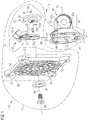
- FIG Figure 6 Based on Figure 6 a first particularly preferred embodiment of a device holder 100 according to the invention with a base B and at least one coupling 10 according to the invention is described first, which is shown in FIG Figure 1 to 5 is shown and will be explained further below.
- This device holder 100 here has two of the couplings 10 according to the invention. They are used to couple two devices 1, specifically two monitors 1 here, to the device holder 100.
- the main components of this device holder 100 include a base B for arrangement on a reference object 2, here specifically a table top 2, and a positioning mechanism 101 articulating the base B and the couplings 10, here specifically a joint arrangement 101, which, among other things, has a cylindrical column 110 and an arcuate cross member 140 crossing the column 110.
- the traverse 140 is detachably connected in the center to the column 110 via an adapter element 120.
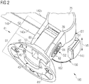
- the traverse 140 is here in the area of its end sections in each case via a lateral sliding sleeve 150 that fully encompasses the traverse 140 in two mutually perpendicular axes KGA, DGA via joints D2, D3 (see also Figure 2 ) rotatably coupled to the couplings 10.
- a cross member cover cap 143 is attached to each of the "head sides" of the cross member 140 as a stop for the lateral sliding sleeves 150, which are otherwise essentially displaceable along the cross member 140 (see FIG Figure 2 ).
- the monitors 1 shown here and held by the device holder 100 - as well as the table top 2 - do not belong to the invention, but are only shown for illustrative purposes. Any cabling or cables that go out from the monitors, but which in reality would of course be connected if necessary, are not shown. However, since the table top 2 functions here as the reference object for the device holder 100, all directions are defined relative thereto.
- the column 110 attached to the base B with a lower end stands “free-standing” vertically or vertically on the table top 2.
- the slightly curved traverse 140 crossing the column 110 runs perpendicular to the column 110.
- the direction parallel to the column 110 is also referred to below as the vertical direction VR and the slightly curved or curved "direction" here essentially parallel to the traverse 140 is also referred to as Horizontal direction denotes HR.
- the two pivot axes DGA of the pivot joints D3 run in the longitudinal direction, i.e. in particular in the vertical direction VR, of the lateral sliding sleeves 150, around which pivot axes DGA the couplings 10 with the monitors 1 relative to the respective Sliding sleeve 150 are rotatably mounted parallel to a table plane of the table top 2.
- the two monitors 1 around the tilting joint axes KGA of the tilting joints D2, which run parallel to the table top 2 - i.e. perpendicular to the pivot axis DGA - can each be tilted or tilted downwards towards the tabletop 2 or upwards away from the tabletop 2.
- the monitors 1 can be rotated or rotated about a coupling axis KA of the pivot bearing D1 of the coupling 10, which runs perpendicularly through a respective screen surface of the monitor 1 and which runs particularly perpendicular to the tilting joint axis KGA, if the distance from one another is sufficiently large.
- This pivot bearing D1 is integrated into the coupling 10.
- the coupling 10 has two coupling parts 11, 41, which are each shown here with a dashed line.
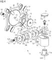
- a first coupling part 11 comprises at least - here from right to left along the coupling axis KA - a rotary disk 23, a locking pin 25, a bearing ring 13, a coupling plate 30, a first centering disk 35 and a fixing screw 36, wherein the components shown here individually in Figure 3 are shown in an assembled state.
- a second coupling part 41 has on one of the coupling plate 30 of the first coupling part 11 facing contact surface 41f on one half or a pivot bearing section S1 of the second coupling part 41 a z. T. inwardly (into the coupling part 41) from the contact surface 41f spaced second pivot bearing part 42 of the pivot bearing D1, as will be explained below.
- the second coupling part 41 in the pivot bearing section S1 - or in the following also called spherical section S1 - of the second coupling part 41 has the shape of a here in Figure 1 spherical cap or spherical cap open in sections at the top with a spherical segment facing away from this coupling plate or a tilting joint piece 60 for the tilting joint D2 continuing in a tilting joint section S2.
- the tilting joint piece 60 corresponds to a fork head counterpart 60 for a fork joint 70 or a fork head 70, which is formed in a “coupling area of the ball segment”, as will also be explained further below.
- the circular disk 23 or rotary disk 23 is circular or circular disk-shaped and comprises two disk sections 24, 26 with different radii 24r, 26r along the coupling axis KA.
- a first disk section 24 is radially reduced with a smaller, first radius 24r and is located closer to the coupling plate 30 than a second disk section 26, which will be explained below
- Side a turntable thread 23g formed in alignment with the coupling axis KA.
- the fixing screw 36 is tightened against this in the assembled state, for example by means of a screwdriver.
- the first disk section 24 offset radially outwardly to the rotary disk thread 23g, there is a relatively smaller rotary disk locking hole 23l, in which the fully cylindrical locking pin 25 is inserted with one of its two ends in the assembled state.
- a flange or the second disk section 26 with a larger, second radius 26r adjoins the first disk section 24 (as part of the turntable) on an end face of the turntable 23 facing away from the coupling plate. In the assembled state, it serves as a stop or safety device for the bearing ring 13 in order to secure the bearing ring 13 against slipping along the coupling axis KA.
- the bearing ring 13 comprises a ring section and three elongated arms 14a, 14b, 15 which protrude vertically upwards from the ring section and run parallel to an annular plane or to the coupling plate 30 and are spaced apart from one another. H. away from the ring section, each formed with an azimuthally extending circle segment surface as a kind of "shielding surface".
- the two outer elongated arms 14a, 14b correspond to actuating levers 14a, 14b or wings 14a, 14b, which protrude tangentially, parallel to one another, from the ring section.
- the aforementioned shielding surfaces of the wings 14a, 14b each extend azimuthally predominantly away from one another.
- the two wings 14a, 14b include two rectangular actuating surfaces running parallel to one another, adjoining or continuing the wings 14a, 14b radially outward, around the wings 14a, 14b for releasing the clutch 10 - as will be explained further below - to be able to compress azimuthally in the direction of the third arm or diaphragm wing 15.
- This runs centrally between the two outer wings 14a, 14b at a distance from them and, like the latter, has an azimuthally extending shielding surface which covers the middle half of a space between the two wings 14a, 14b in a radial direction.
- This azimuthal shielding surface is arranged slightly radially inwardly offset or set back between the two shielding surfaces of the other wings 14a, 14b.
- the wings 14a, 14b can be compressed azimuthally as intended, at least up to this shielding surface, and only then touch or strike against it.
- the wings 14a, 14b cannot be bent too much (inward) when they are actuated.
- an outwardly pointing triangular latching lug 16 is formed which, as will be explained further below in the context of the second coupling part 41, is part of a latching connection with the second Coupling part 41 represents.
- the essentially flat coupling plate 30 is "fort castle” -shaped in plan, ie square with round, outwardly bulging corner areas and comprises two screw holes 32 formed radially one behind the other in the four corner areas for mounting on a monitor according to the standard of a VESA bracket.
- a circular indentation for receiving the centering disk 35 is formed centrally around a coupling axis hole 31k - through which the coupling axis KA extends.
- the indentation is surrounded by radially and azimuthally extending stiffening ribs in order to increase the strength or rigidity of the coupling plate 30 as well as material and weight to save compared to a solid coupling plate.
- Figure 4 can be seen on the back of the coupling plate 30, there is correspondingly in alignment with the turntable securing hole 23l next to the coupling axis hole 31k a coupling plate securing hole 31l in which the above-mentioned locking pin 25 inserted in the turntable 23 in the assembled state its other end is stuck or sitting.
- the coupling plate 30 is secured against rotating relative to the turntable 23 during use.
- any device in particular a monitor, which has fastening holes in accordance with the VESA standard, can be firmly connected to the coupling plate 30 by means of these coupling screws 33.
- the display surface is then parallel to the defined contact plane KE (see Figure 1 ).
- the centering disk 35 for the indentation for receiving the fixing screw 36 for the rotary disk 23 is - similar to a somewhat “thicker" washer - circular with a central countersunk hole. In the assembled state, it serves both to center the fixing screw 36 and as an intermediate “washer” between a head of the fixing screw 36 and a circular indentation in the coupling plate 30 on the coupling part 41 facing the monitor 1 and not visible in use or by the second coupling part 41 facing away from the front of the coupling plate 30 (see Figure 1 ).
- both a bearing ring receptacle 43 and a disk receptacle 53 are connected to one another in the spherical section S1 of the second coupling part 41
- the bearing ring receptacle 43 is arranged in accordance with the first (smaller) disk section 24 of the turntable 23 with the stripped-on bearing ring 13, both closer to the contact surface 41f for the coupling plate 30, and also adapted in terms of shape to the contour or outer shape of the bearing ring 13.
- the disk receptacle 53 for the second (larger) disk section 26 is offset inwardly from the contact surface 41f in the second coupling part 41 (more specifically in the spherical part 41k of the second coupling part 41), so that the bearing ring receptacle 43 supports the second disk section 26 of the turntable 23 from the perspective of the tilting joint or fork head counterpart 60 of the second coupling part 41 engages behind or engages around.
- the bearing ring receptacle 43 and the disk receptacle 53 are also designed in a U-shape opposite to an insertion direction KR (upwards here) with an essentially U-shaped base in order to accommodate the first rotary bearing part 12 of the in FIG Figure 3 shown first coupling part 11 (here from above) into the second pivot bearing part 42 in this insertion direction KR or coupling direction KR to be able to insert or "clip in”.
- the latching lugs 16 described above engage in guides or recesses 46 which are recessed on both sides (here in the upper part of the bearing ring receptacle 43), each of which essentially has the shape of a recessed three-sided prism.
- the wings 14a, 14b can simply be compressed azimuthally as described above, so that the locking lugs 16 are moved out of the recesses 46 and the first rotary bearing part 12 (together with it, e.g. via the coupling plate 30 connected device) against the coupling direction KR can be pulled out of the second pivot bearing part 42 again.
- the rotary disk 23 with the second disk section 26 rests directly in the disk seat 53 of the second rotary bearing part 42 and the bearing ring 13 placed on the first disk section 24 of the rotary disk 23 is mounted in the bearing ring seat 43 of the second rotary bearing part 42 of the rotary bearing D1, so that an undesired mobility beyond certain permissible tolerances along the coupling axis KA is prevented.
- the tilting joint D2 which is only partially shown, comprises the above-mentioned tilting joint piece 60 or fork head counterpart 60 of the second coupling part 41 shown here, which, as already mentioned, is located in the tilting joint section S2 of the second coupling part 41. It is therefore explained below with the aid of Figure 4 described.
- a circular countersink with a central through hole is formed in the tilting joint piece 60 for the rotationally fixed or rotationally secured reception of a perforated washer 64 in a plane parallel to the coupling axis KA.
- a tilting joint washer 63 functioning as a type of “brake disk” is also arranged on the outside parallel to the washer 64 on a side facing away from the tilting joint piece 60.
- the tilting joint D2 includes a tilting joint screw 61 and a tilting joint nut 65, which are described in more detail below. These can be tightened or adjusted against one another, including enclosing the perforated washer 64 and the tilting joint washer 63, so that essentially any desired relative pressure is generated.
- the perforated washer 64 is designed with two small anti-rotation holes 64l and also with a central through hole, which however has a round, but secant-shaped, inner hole profile 64f that is flattened with two inner edges.
- the perforated washer 64 and the tilting joint washer 63 together have approximately the same size as the countersinking of the tilting joint piece 60.
- the same components - that is, the pins 60s in the circular recess, a second perforated washer 64 and a second, appropriately rotated, tilting joint washer 63 - are also on the other, here in Figure 4 not visible, side of the tilting joint piece 60 is formed.
- the above-mentioned tilting joint nut 65 is formed there with a hollow bolt with an internal thread and a two-sided external profile 65f which merges into a D-shaped flange with a flat edge 65f 'on one side.
- the bolt with the two-sided outer profile 65f is about just long enough that it extends through the through hole of the tilting joint 60 to the opposite perforated washer 64, which has a corresponding secant-shaped flattened hole inner profile 64f.
- Matching the internal thread of the tilting joint nut 65, the tilting joint D2 completes the above-mentioned corresponding tilting joint screw 61 with an interposed second centering disk 62 with a flange 62f that is flattened on the top and bottom.
- the two perforated washers 64 are first inserted into the recess of the tilting joint piece 60, that the pins 60s are located in the anti-rotation holes 64l. Subsequently, the tilting joint washers 63 are each placed on the outside of the washers 64. The perforated washers 64 and the tilting joint washers 63 disappear completely in the circular countersinking of the tilting joint piece 60. Thereupon the forked joint 70 or the fork head 70 with the perforated legs is so on the outside over the tilting joint piece 60 or forked head counterpart 60 with the tilting joint Washer 63 pushed or guided so that the through holes are in a common alignment on the tilting joint axis KGA.
- the tilting joint nut 65 with the bolt is guided from a suitable side along the tilting joint axis KGA through the through holes to the second perforated washer 64 on the other side, on the outside the second centering washer 62 is inserted into the flattened inner hole profile 70f of the fork joint 70 and the tilting joint -Screw 61 is screwed to the tilting joint nut 65 or tightened against it as required.
- the tilting joint washers 63 can preferably be formed from steel and / or the washers 64 from a POM material or POM plastic. At least one of the tilting joint washers 63 is particularly preferably designed with a surface knurled or roughened to the POM washer or washer 64 so that the tightness of the tilting joint D2 under tension by means of the tilting joint screw 61 in the associated tilting joint nut 65 is even more precise can be adjusted.
- the second centering washer 62 presses the roughened surface of the tilting joint washer 63 braking more or less depending on the severity of the setting of the tilting joint screw 61 relative to the tilting joint nut 65 against the perforated washer 64.
- the tilting joint D2 is self-retaining and can be adapted to different weights of devices 1 by setting the tilting joint screw 61 against the tilting joint nut 65, so that the tilting joint D2 holds itself at all times, but if necessary by means of a slight, additional application of force User a desired, changed tilt angle can be set.
- the tilting joint D2 comprises a hollow cylindrical fork joint or a fork head 70 with two, the tilting joint piece or fork head counterpart 60 on the outside engaging, from a hollow cylinder 70h of the fork joint 70 essentially tangentially protruding, perforated legs.
- One of Leg has a countersunk, flattened inner hole profile 70f for receiving the flattened flange 62f of the second centering disk 62.
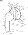
- the other leg is designed with a D-shaped countersinking flattened on one side for almost flush reception of the flange with flat edge 65f 'of the tilting joint nut 65 flattened on one side, as shown in FIG Figure 5 emerges.
- the hollow cylinder 70h of the fork joint 70 forms an anchorage for an inner sleeve 71 of a rotary joint D3.
- inner sleeve 71 is an in Figure 7 Shown inner pin 170 of the sliding sleeve 150 rotatably mounted. This is among other things in the overall view according to the Figures 5 and 6th shown.
- the inner sleeve 71 and the hollow cylinder 70h comprise interlocking elements as a rotation lock or mutual anchoring.
- this element is implemented by means of a bead 71w on an outer profile of the inner sleeve 71 (see FIG Figure 4 ), which engages in a corresponding "depression" of the hollow cylinder 70h formed on the inside in the hollow cylinder 70h, which cannot be seen.
- the hollow cylinder 70h is designed to receive a washer 72 with a flattened inner hole profile 72f.
- a washer 73 rests on this washer 72, which washer can be designed like the tilting joint washer 63 already described.
- FIG. 4 Shown blown out above it, there is a swivel joint screw 74 for adjusting the stiffness of the swivel joint D3 against an internal thread 170g in the internal pin 170 (see FIG Figure 7 ), and a swivel joint cap 75 for optical concealment or covering of the swivel joint screw 74 in the assembled state from above, blown out even further.
- the swivel joint cover cap 75 comprises a number of clamping webs 75k or click elements for fixing the swivel joint cover cap 75 in the hollow cylinder 70h of the fork joint 70.
- Figure 7 shows an exploded detailed illustration of the individual components of a lateral sliding sleeve 150, which, as in FIG Figure 5 shown, in an assembled state together with the hollow cylinder 70h of the fork joint 70 forms the rotary joint D3 on the cross member 150 for rotating the coupling 10 with the monitor 1 in the horizontal.
- the swivel joint D3 comprises the sliding sleeve 150, which on the upper side receives the inner pin 170 in an upper section, comprises a traverse through opening 151 in a middle section for guiding the traverse 140 and on the underside, in a lower section, a sliding sleeve locking element 160 or a Has vertical rotary knob 160 in order to releasably position the sliding sleeve 150 at almost any point along or on the traverse 140.
- the sliding sleeve 150 surrounds a C-shaped slotted cover sleeve 162 for the final, visually appealing covering of the inner structure of the sliding sleeve 150.
- the inner pin 170 has a flange 172 in which three countersunk holes 174 are formed, which are also arranged at an angular distance of 120 ° from one another, perpendicular, parallel to the pivot axis DGA, through the flange 172 and which, when used as intended Arrangement of the inner journal 170 with the base 175 in the rectangular recess 155 of the sliding sleeve 150 are in alignment with the above-mentioned bores 156 of the sliding sleeve 150.
- the flange 172 is the actual round "bolt section" of the inner pin 170, which is formed on the upper face with the above-mentioned internal thread 170g, against which the above-mentioned swivel screw 74 (see Figure 4 ) to adjust the stiffness of the swivel joint D3 from the inner pin 170 and inner sleeve 71 can be tightened.
- the upper end of the bolt section of the inner peg 170 remote from the base in this case the upper end of the bolt section, it also has, on the outer profile side, in two opposite areas, secant-shaped flattened notches 171 for rotationally fixed coupling with the secant-shaped flattened inner hole profile 72f of the above-mentioned washer 72 (see also Figure 4 ) on.
- the base 175 is arranged in the rectangular recess 155 and then the flange 172 of the inner pin 170 with the countersunk holes 174 by means of countersunk screws 166 against (correspondingly smaller) square nuts 164 in the (smaller) radial slot recesses 154 of the sliding sleeve 150 tightened or screwed in the vertical direction VR.
- the sliding sleeve 150 In the middle section of the sliding sleeve 150 is - arranged in an orientation perpendicular to the swivel joint axis DGA, here horizontal - the mentioned traverse through opening 151 for the traverse 140, which essentially has a rectangular cross section that is adapted to the shape of the traverse 140 and for this purpose is very slightly arched upwards and downwards.
- a hole 150l through the sliding sleeve 150 is formed axially along the pivot axis DGA.
- Below the traverse through-opening 151 in a lower section of the sliding sleeve 150 runs parallel to the traverse through-opening 151 an essentially cuboidal, also radially to the pivot axis DGA, but larger slot recess 153 compared to the aforementioned radial (smaller) slot recesses 154 153 the hole 150l runs and finally opens on the underside within a circular countersink 157, not visible here.
- a thread 161 or a threaded rod 161 of the sliding sleeve fixing element 160 or the vertical rotary knob 160 for locking against the cross member 140 can be passed through this hole 150l be screwed tightly by inserting a correspondingly larger rectangular nut 163 into the (larger) radial slot recess 153 so that the threaded rod 161 can be tightened against the cross member 140 via the (larger) rectangular nut 163.
- the above-mentioned countersink 157 accommodates a flange section of the vertical rotary knob 160.
- the aforementioned cover sleeve 162 Over the three described sections of the sliding sleeve 150, five narrow guide grooves 152r extend parallel to the swivel joint axis DGA in the vertical direction VR, some of which are interrupted, among other things, by the crossbar through-opening 151. Matching these guide grooves 152r, the aforementioned cover sleeve 162 in turn comprises five narrow guide lugs 162n which, when the cover sleeve 162 is slipped on or placed on the sliding sleeve 150, engage or are guided accordingly.
- the cover sleeve 162 In order to pass through the traverse 140, the cover sleeve 162 has on a one facing away from the column 110 On the outside, an analog traverse through-opening 162a with a cross-section corresponding to the traverse through-opening 151 of the sliding sleeve 150. On the opposite inner side of the cover sleeve 162 facing the column 110, it simply has a vertically continuous slot at least in the width of the cross member through-opening 162a on the outer side.
- each of the sliding sleeves 150 can be moved as desired on the respective half of the traverse 140 and there, here from below, conveniently fixed against the traverse 140 without tools. Due to the arrangement of the sliding sleeve locking element 160 on an underside of the cross member 140, there is also no visual impairment whatsoever.
- the positioning mechanism 101 of the device holder 100 comprises an adapter element 120 which receives the cross member 140 in a cross member through opening 121 and thus allows the cross member 140 to be displaced along a longitudinal direction of the column 110 (hereinafter referred to as the vertical direction VR because the column 110 is usually vertical).
- the adapter element 120 is essentially cuboid (apart from the indentation 152 described below) and comprises the essentially rectangular (adapted to the cross-section of the cross-member 140) cross-member through-opening 121 running perpendicular to the vertical direction VR for receiving the cross-member 140 in the almost completely encompassing manner Portrait. Furthermore, as mentioned, it has an indentation 125 which is essentially in the form of a segment of a cylinder, here specifically semicylindrical, the cylinder axis of which runs in the vertical direction VR.
- This indentation 125 is located, as seen from the cross member 140, along a horizontally running screw axis SA behind the cross member through opening 121, ie between the cross member through opening 121 and the column 110, and in the assembled state clings to the column 110 with its concave side or encompasses at least part of the circumference of the column 110, as in FIG Figure 6 you can see.
- the section of the Adapter element 120 between crossbar through-opening 121 and indentation 125 is divided into an upper and a lower part by a, here horizontal, slot 122.
- a first fastening hole 141 extends transversely to the horizontal direction HR through the arched traverse 140 from a concave side 142v to a convex side 142x or vice versa.
- a further fastening hole 123 then extends through the adapter element 120, namely perpendicularly through the crossbar through opening 121 and the indentation 125 of the adapter element 120.
- a traverse locking element 131 with an external thread located on one end section is passed through these fastening holes 141, 123 and screwed into a threaded hole 132l of a slot nut 132 so that the cross member 140, the adapter element 120 and the slot nut 132 are connected to one another.
- the threaded hole 132l in the sliding block 132 is formed transversely through the sliding block 132.
- cross member 140 Through the fastening holes 141, 123 and the threaded bore 132l, the components mentioned (cross member 140, adapter element 120, sliding block 132) can be pulled together by a user by hand using a horizontal rotary knob 131d as part of the cross member locking element 131.
- the function of the sliding block 132 for holding the cross member 140 on the column 110 will be explained below.
- the traverse 140 is, unlike in the exploded view in Figure 7 shown, not in front of the adapter element 120 or between the adapter element 120 and the crossbar locking element 131, but within the crossbar through opening 121 of the adapter element 120.
- the crossbar locking element 131 then fits with a flange of the horizontal rotary knob 131d in a circular Countersink 124 of the adapter element 120 and pulls the sliding block 132 relative to the adapter element 120 against an inside of the groove rail 112 and thus the adapter element 120 against the column 110.
- the sliding block 132 is here an elongated, trapezoidal parallelepiped with the mentioned threaded hole 132l for screwing or screwing in the traverse locking element 131. It slides in a longitudinal direction of the column 110 on one side inward, radially outward to the lateral surface 111 of the column 110 widening channel 112k in the column 110.
- the lateral surface 111 of the column 110 has a gap 112s to the channel 112k. Through this gap 112s, which is formed by protruding boundaries or side walls of the channel 112k or the lateral surface 111, the channel 112k is open or accessible to the outside.
- the gap 112s is significantly narrower relative to the inner channel 112k.
- the gap 112s of the channel 112k is preferably at least as wide as the locking element 131 (or a threaded section of the locking element 131), and at the same time narrower than the sliding block 132 screwed onto the locking element 131.
- the sliding block 132 thus slides guided in the groove rail 112 , wherein the traverse locking element 131 screwed into the sliding block 132 protrudes through the gap 112s out of the channel 112k or into the channel 112k.
- a flat side of the slot nut 132 which is triangular in cross-section and on which the threaded hole 132l is also located, facing the gap 112s, can thereby be pulled evenly by the crossbeam locking element 131 against the "protrusion" or the boundaries of the channel 112k.
- the slot nut 132 engages behind the protrusion of the channel 112k of the slot rail 112.
- the sliding block 132 can be pushed into the channel 112k from an upper side of the column 110.
- the column 110 comprises a column cover cap 113, which can also be designed for fastening with a number of clamping webs 113k or click elements for fixing the column cover cap 75 on the top of the column 110. With this column cover cap 113, the channel or the column 110 is then suitably closed towards the top after the sliding block 132 has been inserted.
- the adapter element 120 comprises two in the vertical direction VR parallel to the indentation 125 and perpendicularly through the above-mentioned slot 122 (Vertical) holes 126 for receiving two clamping screws 127 for clamping the traverse 140 in the traverse through opening 121 of the adapter element 120 without play.
- the vertical holes 126 include a matching internal thread at least above the slot 122, preferably at least when the adapter element 120 is formed from metal, for example.
- the clamping screws 127 in the upper region of the adapter element 120 could also be countered with suitable rectangular nuts which, for. B. in corresponding slot recesses, similar to the above-mentioned slot recesses, could be used via the indentation 125 in the adapter element 120.
- FIG. 9 a second preferred embodiment of a device holder 100 according to the invention is shown.
- This device holder 100 ' is also designed with a coupling 10 according to the invention, but has a different joint arrangement 101' which, as shown here, can be mounted on the base B as an alternative to the joint arrangement 101 or in addition - as not shown here - to the joint arrangement 101 the lateral sliding sleeves 150 of the device holder 100 can be interposed.
- the illustrated embodiment comprises the joint arrangement 101 '- in addition to the rotary joint D3 on the hollow cylinder 70h of the fork joint 70 - two further, similar rotary joints D4', D5 ', which have a height-adjustable or vertically pivotable - forming a movable parallelogram - double arm 102' and a connect horizontal arm 103 'to each other or to the base B in an articulated manner.
- the double arm 102 ' At the other end of the double arm 102 ', at which it is not connected to the horizontal arm 103', the latter is correspondingly supported in the hollow cylinder 70h with the formation of the swivel joint D3 with an inner journal which cannot be seen.
- Base B shown - are coupled directly to the inner pin 170 of the lateral sliding sleeve 150.
- the swivel joint D5 ' is created this time between the relevant sliding sleeve 150 on the cross member 140 and the horizontal arm 103', so that the joint arrangement 101, 101 'as a whole, for example, at least the joints D1, D2, D3, D4', D5 'one or more times may have.
- the base B can be modified accordingly so that it holds the device holder 100 in a stable manner or has a corresponding counterweight in order to be able to hold at least the additional arms 102 ', 103' in any positions or positions without any problems.
- the device holder can also be designed in such a way that it can hold more than one device, in particular several monitors or tablets.
- Another base can also be used, e.g. B. a "through-table solution" in which the table clamp does not sit on the edge of the table top, but in an opening within a table surface of the table top, or a base for screwing to a wall or the like.
- the coupling plate of the device holder can be adapted to other standardized devices.
- the monitors shown and the tablets can be exchanged and / or combined with one another as required.
- the traverse can be enclosed by further suitable sliding sleeves, not described in the exemplary embodiments shown above, on each of which there is, for example, a tablet holder for a tablet.
- other fastening elements than the locking elements described can also be used for fixing the crossbeam on the column or the sliding sleeves on the crossbeam, for example.
- the arcuate cross-member shown could also be arranged the other way around in order to generate a convex screen front.
- the use of the indefinite article "a" or "an” does not exclude the possibility that the relevant features can also be present more than once.
- the term “arrangement” does not exclude the fact that the component in question consists of several interacting subcomponents, which may also be spatially distributed.
Landscapes
- Engineering & Computer Science (AREA)
- General Engineering & Computer Science (AREA)
- Mechanical Engineering (AREA)
- Quick-Acting Or Multi-Walled Pipe Joints (AREA)
- Clamps And Clips (AREA)
- Pivots And Pivotal Connections (AREA)
Applications Claiming Priority (1)
| Application Number | Priority Date | Filing Date | Title |
|---|---|---|---|
| DE102019127030.8A DE102019127030A1 (de) | 2019-10-08 | 2019-10-08 | Kupplung |
Publications (2)
| Publication Number | Publication Date |
|---|---|
| EP3805576A2 true EP3805576A2 (fr) | 2021-04-14 |
| EP3805576A3 EP3805576A3 (fr) | 2021-06-16 |
Family
ID=72615743
Family Applications (1)
| Application Number | Title | Priority Date | Filing Date |
|---|---|---|---|
| EP20197724.6A Withdrawn EP3805576A3 (fr) | 2019-10-08 | 2020-09-23 | Couplage |
Country Status (2)
| Country | Link |
|---|---|
| EP (1) | EP3805576A3 (fr) |
| DE (1) | DE102019127030A1 (fr) |
Cited By (2)
| Publication number | Priority date | Publication date | Assignee | Title |
|---|---|---|---|---|
| CN114962890A (zh) * | 2022-05-26 | 2022-08-30 | 浪潮商用机器有限公司 | 一种可调节升降机构 |
| EP4145036A4 (fr) * | 2021-07-12 | 2023-08-23 | Shanghai Linghai Trading Center | Bras de support d'ordinateur dont l'angle peut être ajusté librement |
Families Citing this family (1)
| Publication number | Priority date | Publication date | Assignee | Title |
|---|---|---|---|---|
| DE202022106335U1 (de) * | 2022-11-10 | 2024-02-19 | Dewertokin Gmbh | Gerät mit einer Schwenkhalterung |
Citations (1)
| Publication number | Priority date | Publication date | Assignee | Title |
|---|---|---|---|---|
| DE202016100617U1 (de) | 2016-02-08 | 2016-02-18 | Rk Rose + Krieger Gmbh Verbindungs- Und Positioniersysteme | Halterung für Anzeige- oder Bediengeräte |
Family Cites Families (14)
| Publication number | Priority date | Publication date | Assignee | Title |
|---|---|---|---|---|
| DE3744706A1 (de) * | 1987-03-28 | 1988-12-15 | Rose Elektrotech Gmbh | Geraetetraeger fuer computergeraete od. dgl. |
| DE29600889U1 (de) * | 1996-01-19 | 1996-03-07 | Bergmann, Wolfgang, 95448 Bayreuth | Haltevorrichtung für zu lackierende Gegenstände |
| GB2384611B (en) * | 1998-12-23 | 2003-12-17 | Jerry Moscovitch | Computer display screen system and adjustable screen mount and swinging screens therefor |
| GB2360894B (en) * | 2000-03-30 | 2004-11-10 | Peter Thomas Bosson | Display device support system |
| AUPS285202A0 (en) * | 2002-06-07 | 2002-06-27 | Claiteal Pty Ltd | Stand for flat panel display |
| US7369401B1 (en) * | 2004-03-26 | 2008-05-06 | Floersch Peter J | Display monitor mounting apparatus |
| WO2006132938A2 (fr) * | 2005-06-03 | 2006-12-14 | Steel Case Development Corporation | Assemblage de bras de support |
| US7922132B2 (en) * | 2007-01-24 | 2011-04-12 | Humanscale Corporation | Accessory holder |
| US8191487B2 (en) * | 2009-02-25 | 2012-06-05 | Humanscale Corporation | Wall-mounted accessory holder |
| US9228693B2 (en) * | 2011-01-07 | 2016-01-05 | Jeff Ditges | Equipment mounting structure |
| US9400083B2 (en) * | 2014-04-24 | 2016-07-26 | Knoll, Inc. | Support apparatus for multiple display devices |
| US10422468B2 (en) * | 2015-04-20 | 2019-09-24 | Innovative Office Products, Llc | Articulating support arm with improved tilter and friction joint |
| US9841139B1 (en) * | 2017-04-13 | 2017-12-12 | Tct Nanotec Co., Ltd. | Holder |
| CN207539569U (zh) * | 2017-12-06 | 2018-06-26 | 广州市健翼电子有限公司 | 多屏桌面显示器支架 |
-
2019
- 2019-10-08 DE DE102019127030.8A patent/DE102019127030A1/de active Pending
-
2020
- 2020-09-23 EP EP20197724.6A patent/EP3805576A3/fr not_active Withdrawn
Patent Citations (1)
| Publication number | Priority date | Publication date | Assignee | Title |
|---|---|---|---|---|
| DE202016100617U1 (de) | 2016-02-08 | 2016-02-18 | Rk Rose + Krieger Gmbh Verbindungs- Und Positioniersysteme | Halterung für Anzeige- oder Bediengeräte |
Cited By (2)
| Publication number | Priority date | Publication date | Assignee | Title |
|---|---|---|---|---|
| EP4145036A4 (fr) * | 2021-07-12 | 2023-08-23 | Shanghai Linghai Trading Center | Bras de support d'ordinateur dont l'angle peut être ajusté librement |
| CN114962890A (zh) * | 2022-05-26 | 2022-08-30 | 浪潮商用机器有限公司 | 一种可调节升降机构 |
Also Published As
| Publication number | Publication date |
|---|---|
| EP3805576A3 (fr) | 2021-06-16 |
| DE102019127030A1 (de) | 2021-04-08 |
Similar Documents
| Publication | Publication Date | Title |
|---|---|---|
| DE60128109T2 (de) | Vorrichtung zum fixieren von teleskopisch zusammenwirkenden elementen | |
| EP1283969B1 (fr) | Console | |
| EP1613890B1 (fr) | Pied | |
| EP2586944B1 (fr) | Charnière dotée d'éléments de réglage et d'une couronne de réglage destinée à ces éléments de réglage | |
| DE20006335U1 (de) | Verbindungseinheit zum winkeleinstellbaren Verbinden mindestens zweier Lautsprecherboxen und entsprechend verbundene Lautsprecherboxen | |
| EP3805576A2 (fr) | Couplage | |
| DE60011003T2 (de) | Permanente Verankerungsvorrichtung | |
| EP2553328B1 (fr) | Fixation d'un mât pour lampadaire | |
| EP1076617A1 (fr) | Dispositif de support et de fixation pour conducteurs aeriens | |
| EP3922869B1 (fr) | Dispositif de liaison destiné à être fixé à un profilé creux, ainsi qu'ensemble de stabilisation et dispositif de stabilisation | |
| DE19735331C2 (de) | Vorrichtung zur Aufnahme von Gegenständen | |
| DE10228888B4 (de) | Punkthalter für Verbundsicherheitsglasplatte | |
| EP0583701B1 (fr) | Console pivotante | |
| DE4420037B4 (de) | Verbindungselement insbesondere zur Montage von Türdrückern, Griffen od. dgl. an Türen, Fenstern od. dgl. | |
| EP1887151B1 (fr) | Support angulaire | |
| DE4216612A1 (de) | Einachsscharnier | |
| DE102004048879A1 (de) | Anlenkung | |
| EP1905916A1 (fr) | Dispositif de fixation d'objets plats au plafond, particulièrement de feuilles de verre comme protection contre la fumée | |
| DE202010001441U1 (de) | Justiersystem für Bauelemente | |
| EP0057454B1 (fr) | Dispositif de suspension réglable en hauteur | |
| EP0722026B1 (fr) | Dispositif pour la fixation d'un élément de construction en forme de plaque sur un mur ou similaire | |
| DE10219589C1 (de) | Pritschenrolle | |
| DE29902768U1 (de) | Montageplatte für Möbelscharniere | |
| AT512082B1 (de) | Lampenhalter für eine einbauleuchte | |
| WO2025046478A1 (fr) | Poignée de porte verrouillable et ensemble poignée de porte comprenant au moins une poignée de porte verrouillable |
Legal Events
| Date | Code | Title | Description |
|---|---|---|---|
| PUAI | Public reference made under article 153(3) epc to a published international application that has entered the european phase |
Free format text: ORIGINAL CODE: 0009012 |
|
| STAA | Information on the status of an ep patent application or granted ep patent |
Free format text: STATUS: THE APPLICATION HAS BEEN PUBLISHED |
|
| AK | Designated contracting states |
Kind code of ref document: A2 Designated state(s): AL AT BE BG CH CY CZ DE DK EE ES FI FR GB GR HR HU IE IS IT LI LT LU LV MC MK MT NL NO PL PT RO RS SE SI SK SM TR |
|
| AX | Request for extension of the european patent |
Extension state: BA ME |
|
| PUAL | Search report despatched |
Free format text: ORIGINAL CODE: 0009013 |
|
| AK | Designated contracting states |
Kind code of ref document: A3 Designated state(s): AL AT BE BG CH CY CZ DE DK EE ES FI FR GB GR HR HU IE IS IT LI LT LU LV MC MK MT NL NO PL PT RO RS SE SI SK SM TR |
|
| RIC1 | Information provided on ipc code assigned before grant |
Ipc: F16B 9/00 20060101AFI20210510BHEP Ipc: F16B 21/08 20060101ALI20210510BHEP Ipc: F16B 2/06 20060101ALI20210510BHEP Ipc: F16B 37/04 20060101ALI20210510BHEP Ipc: F16M 11/04 20060101ALI20210510BHEP Ipc: F16M 11/10 20060101ALI20210510BHEP Ipc: F16M 11/20 20060101ALI20210510BHEP Ipc: F16M 11/24 20060101ALI20210510BHEP Ipc: F16M 13/02 20060101ALI20210510BHEP |
|
| STAA | Information on the status of an ep patent application or granted ep patent |
Free format text: STATUS: REQUEST FOR EXAMINATION WAS MADE |
|
| 17P | Request for examination filed |
Effective date: 20211203 |
|
| RBV | Designated contracting states (corrected) |
Designated state(s): AL AT BE BG CH CY CZ DE DK EE ES FI FR GB GR HR HU IE IS IT LI LT LU LV MC MK MT NL NO PL PT RO RS SE SI SK SM TR |
|
| STAA | Information on the status of an ep patent application or granted ep patent |
Free format text: STATUS: EXAMINATION IS IN PROGRESS |
|
| 17Q | First examination report despatched |
Effective date: 20230508 |
|
| STAA | Information on the status of an ep patent application or granted ep patent |
Free format text: STATUS: THE APPLICATION IS DEEMED TO BE WITHDRAWN |
|
| 18D | Application deemed to be withdrawn |
Effective date: 20241029 |