EP3806529A1 - Procédé et appareil de transmission de données - Google Patents
Procédé et appareil de transmission de données Download PDFInfo
- Publication number
- EP3806529A1 EP3806529A1 EP19823093.0A EP19823093A EP3806529A1 EP 3806529 A1 EP3806529 A1 EP 3806529A1 EP 19823093 A EP19823093 A EP 19823093A EP 3806529 A1 EP3806529 A1 EP 3806529A1
- Authority
- EP
- European Patent Office
- Prior art keywords
- qfi
- message
- length
- pdu session
- computer program
- Prior art date
- Legal status (The legal status is an assumption and is not a legal conclusion. Google has not performed a legal analysis and makes no representation as to the accuracy of the status listed.)
- Pending
Links
Images


Classifications
-
- H—ELECTRICITY
- H04—ELECTRIC COMMUNICATION TECHNIQUE
- H04W—WIRELESS COMMUNICATION NETWORKS
- H04W76/00—Connection management
- H04W76/10—Connection setup
- H04W76/12—Setup of transport tunnels
-
- H—ELECTRICITY
- H04—ELECTRIC COMMUNICATION TECHNIQUE
- H04L—TRANSMISSION OF DIGITAL INFORMATION, e.g. TELEGRAPHIC COMMUNICATION
- H04L69/00—Network arrangements, protocols or services independent of the application payload and not provided for in the other groups of this subclass
- H04L69/30—Definitions, standards or architectural aspects of layered protocol stacks
- H04L69/32—Architecture of open systems interconnection [OSI] 7-layer type protocol stacks, e.g. the interfaces between the data link level and the physical level
- H04L69/322—Intralayer communication protocols among peer entities or protocol data unit [PDU] definitions
- H04L69/327—Intralayer communication protocols among peer entities or protocol data unit [PDU] definitions in the session layer [OSI layer 5]
-
- H—ELECTRICITY
- H04—ELECTRIC COMMUNICATION TECHNIQUE
- H04W—WIRELESS COMMUNICATION NETWORKS
- H04W28/00—Network traffic management; Network resource management
- H04W28/02—Traffic management, e.g. flow control or congestion control
- H04W28/0252—Traffic management, e.g. flow control or congestion control per individual bearer or channel
- H04W28/0263—Traffic management, e.g. flow control or congestion control per individual bearer or channel involving mapping traffic to individual bearers or channels, e.g. traffic flow template [TFT]
-
- H—ELECTRICITY
- H04—ELECTRIC COMMUNICATION TECHNIQUE
- H04W—WIRELESS COMMUNICATION NETWORKS
- H04W28/00—Network traffic management; Network resource management
- H04W28/02—Traffic management, e.g. flow control or congestion control
- H04W28/0268—Traffic management, e.g. flow control or congestion control using specific QoS parameters for wireless networks, e.g. QoS class identifier [QCI] or guaranteed bit rate [GBR]
-
- H—ELECTRICITY
- H04—ELECTRIC COMMUNICATION TECHNIQUE
- H04W—WIRELESS COMMUNICATION NETWORKS
- H04W28/00—Network traffic management; Network resource management
- H04W28/16—Central resource management; Negotiation of resources or communication parameters, e.g. negotiating bandwidth or QoS [Quality of Service]
- H04W28/24—Negotiating SLA [Service Level Agreement]; Negotiating QoS [Quality of Service]
-
- H—ELECTRICITY
- H04—ELECTRIC COMMUNICATION TECHNIQUE
- H04W—WIRELESS COMMUNICATION NETWORKS
- H04W76/00—Connection management
- H04W76/10—Connection setup
- H04W76/11—Allocation or use of connection identifiers
-
- H—ELECTRICITY
- H04—ELECTRIC COMMUNICATION TECHNIQUE
- H04W—WIRELESS COMMUNICATION NETWORKS
- H04W76/00—Connection management
- H04W76/20—Manipulation of established connections
- H04W76/22—Manipulation of transport tunnels
-
- H—ELECTRICITY
- H04—ELECTRIC COMMUNICATION TECHNIQUE
- H04W—WIRELESS COMMUNICATION NETWORKS
- H04W80/00—Wireless network protocols or protocol adaptations to wireless operation
- H04W80/02—Data link layer protocols
-
- H—ELECTRICITY
- H04—ELECTRIC COMMUNICATION TECHNIQUE
- H04W—WIRELESS COMMUNICATION NETWORKS
- H04W76/00—Connection management
- H04W76/10—Connection setup
- H04W76/19—Connection re-establishment
Definitions
- the present invention relates to the field of wireless communications, and in particular, to a data transmission method and an apparatus.
- 5G fifth-generation
- 5G supports various types of network deployment and application types, including higher-rate experience and a higher-bandwidth access capability, lower-latency higher-reliability information exchange, access and management of massive low-cost machine-type communication devices, and the like.
- 5G defines a QoS management architecture based on a quality of service (quality of service, QoS) flow, and defines a data packet transmission mechanism over an air interface based on a data radio bearer (data radio bearer, DRB).
- QoS quality of service
- DRB data radio bearer
- one or more data flows for example, an Internet Protocol (Internet Protocol, IP) flow
- IP Internet Protocol
- one PDU session includes one or more QoS flows.
- Data packets in one or more QoS flows may be carried on one DRB for transmission.
- Same forwarding processing such as a same scheduling policy, queue management policy, and rate matching policy, is performed on the data packets that are in one or more QoS flows and that are carried on one DRB.
- QoS flow ID QoS flow ID
- QFI QoS flow ID
- a QFI is 6 bits in length.
- one PDU session may include 0 to 63 QoS flows.
- one PDU session may include more QoS flows.
- quantities of QoS flows included in different PDU sessions may vary greatly.
- Embodiments of this application provide a data transmission method that avoids resource waste and improves data transmission efficiency.
- an embodiment of this application provides a data transmission method.
- the method includes: determining, by a core network CN device, a length of a quality of service flow identifier QFI used when a protocol data unit PDU session is established or modified for a terminal device; and sending, by the CN device, a first message to an access network RAN device, where the first message includes length information of at least one QFI.
- the QFI length information is at least one of the following three parameters: a length value of the QFI, a value range of the QFI, and a length class of the QFI.
- QFIs of all quality of service QoS flows or QFIs of some QoS flows in one PDU session correspond to one piece of the QFI length information.
- the first message is a PDU session resource establishment request message, a PDU session resource update request message, or an initial context establishment message.
- the CN device can determine, based on a service requirement and/or a policy and charging control rule of the PDU session, a QFI length, and notify the RAN device of the QFI length, so that a QFI field of an appropriate length is carried during data transmission between the CN device and the RAN device. This avoids resource waste, and improves data transmission efficiency.
- an embodiment of this application provides a data transmission method.
- the method includes: receiving, by an access network RAN device, a first message from a core network CN device, where the first message includes length information of at least one quality of service flow identifier QFI; and sending, by the RAN device, a second message to a terminal device, where the second message includes the length information of the at least one QFI.
- the QFI length information is at least one of the following three parameters: a length value of the QFI, a value range of the QFI, and a length class of the QFI.
- QFIs of all quality of service QoS flows or QFIs of some QoS flows in one protocol data unit PDU session correspond to one piece of the QFI length information.
- the first message is a PDU session resource establishment request message, a PDU session resource update request message, or an initial context establishment message.
- the second message is a radio resource management RRC connection re-establishment request message, an RRC reconfiguration message or an RRC connection resume message.
- the RAN device can notify the terminal device of a QFI length determined by the CN device, so that a QFI field of an appropriate length is carried during data transmission between the RAN device and the terminal device. This avoids resource waste, and improves data transmission efficiency.
- an embodiment of this application provides a data transmission method.
- the method includes: determining, by a core network CN device, a length of a quality of service flow identifier QFI used when a protocol data unit PDU session is modified for a terminal device; and sending, by the CN device, a third message to an access network RAN device, where the third message includes a mapping relationship of at least one QFI.
- the QFI mapping relationship includes a correspondence between a QFI that is of a first length and that is used by at least one QoS flow in the PDU session before the PDU session is modified and a QFI that is of a second length and that is used by the at least one QoS flow after the PDU session is modified.
- the third message further includes length information of the at least one QFI.
- the QFI length information is at least one of the following three parameters: a length value of the QFI, a value range of the QFI, and a length class of the QFI.
- the third message is a PDU session resource update request message.
- the CN device can determine, based on a change of a service requirement and/or a policy and charging control rule of the PDU session, an updated QFI length, and notify the RAN device of a mapping relationship between a previous QFI and an updated QFI of each QoS flow, so that the updated QFI is carried during data transmission between the CN device and the RAN device. In this way, continuity of data transmission is maintained.
- an embodiment of this application provides a data transmission method.
- the method includes: receiving, by an access network RAN device, a third message from a core network CN device, where the third message includes a mapping relationship of at least one QFI; and sending, by the RAN device, a fourth message to a terminal device, where the fourth message includes the mapping relationship of at least one QFI.
- the QFI mapping relationship includes a correspondence between a QFI that is of a first length and that is used by at least one QoS flow in the PDU session before the PDU session is modified and a QFI that is of a second length and that is used by the at least one QoS flow after the PDU session is modified.
- the QFI length information is at least one of the following three parameters: a length value of the QFI, a value range of the QFI, and a length class of the QFI.
- the third message is a PDU session resource update request message.
- the fourth message is an RRC reconfiguration message or an RRC connection resume message.
- the RAN device notifies the terminal device of a mapping relationship between a previous QFI and an updated QFI of each QoS flow, so that the updated QFI is carried during data transmission between the RAN device and the terminal device. In this way, continuity of data transmission is maintained.
- a core network device for performing the method according to any one of the first aspect or the third aspect, or the possible implementations of the first or the third aspect.
- the core network device may include a unit that is configured to perform the method according to any one of the first aspect or the third aspect, or the possible implementations of the first or the third aspect.
- an access network device for performing the method according to any one of the second aspect or the fourth aspect, or the possible implementations of the second or the fourth aspect.
- the access network device may include a unit that is configured to perform the method according to any one of the second aspect or the fourth aspect, or the possible implementations of the second or the fourth aspect.
- a core network device includes a memory and a processor, where the memory is configured to store a computer program and the processor is configured to invoke the computer program from the memory and run the program, so that the core network device performs the method according to any one of the first aspect or the third aspect, or the possible implementations of the first or the third aspect.
- an access network device includes a memory and a processor, where the memory is configured to store a computer program and the processor is configured to invoke the computer program from the memory and run the program, so that the access network device performs the method according to any one of the second aspect or the fourth aspect, or the possible implementations of the second or the fourth aspect.
- a computer program product includes computer program code.
- the computer program code is run by a communication unit, a processing unit, a transceiver or a processor of a communication device (such as an access network device or a terminal device), the communication device is enabled to perform the method according to any one of the first aspect to the fourth aspect, or the possible implementations of the first aspect to the fourth aspect.
- a computer-readable storage medium stores a program, and the program enables a computer to perform the method according to any one of the first aspect to the fourth aspect, or the possible implementations of the first aspect to the second aspect.
- system and “network” may be used interchangeably in this specification.
- network may be used interchangeably in this specification.
- the term “and/or” in this specification describes only an association relationship for describing associated objects and represents that three relationships may exist. For example, A and/or B may represent the following three cases: Only A exists, both A and B exist, and only B exists.
- the character “/” in this specification generally indicates an "or" relationship between the associated objects.
- a data transmission method and apparatus provided in the embodiments of this application are applicable to data transmission of QoS flows that are between a terminal device and a network device and can be indicated by QoS flow identifiers of different lengths.
- a communications system includes a terminal device and a network side device.
- FIG. 1 shows a network side part 100 of a communications system according to an embodiment of this application.
- the network side part 100 includes a next generation core (next generation core, NGC) (also referred to as 5GC) and a next generation radio access network (next generation radio access network, NG-RAN).
- the 5GC mainly includes a control plane network element (such as a mobility management function (access and mobility management function, AMF) and a session management function (session management function, SMF)) and a user plane network element (user plane function, UPF).
- AMF access and mobility management function
- SMF session management function
- UPF user plane function
- the AMF is mainly responsible for access and mobility management of the terminal device.
- the SMF is mainly responsible for session (session) management, terminal IP address assignment, and the like.
- the UPF is mainly responsible for data packet routing and forwarding, QoS management, and the like.
- the AMF, the SMF, and the UPF may also be referred to as core network (core network, CN) devices.
- a network element in the NG-RAN mainly includes a next-generation base station, for example, a next-generation Node B (next-generation Node B, gNB), a next-generation evolved Node B (next-generation evolved Node B, ng-eNB), or the like.
- the gNB and the ng-eNB are also referred to as RAN devices, and provide user plane and control plane functions.
- An interface between the 5GC and the NG-RAN may be defined as an NG interface.
- a control plane interface between the 5GC and the NG-RAN may be defined as an NG-C interface
- a user plane interface between the 5GC and the NG-RAN may be defined as an NG-U interface
- An interface between different network elements (such as two gNBs) in the NG-RAN may be defined as an Xn interface. It should be understood that names of the interfaces are examples, and the interfaces may be alternatively defined as other names. This is not limited in the embodiments of this application.
- the network element in the NG-RAN in FIG. 1 may alternatively be an access point (access point, AP) in a wireless local area network (Wireless Local Area Networks, WLAN), a base transceiver station (base transceiver station, BTS) in GSM or CDMA, a NodeB (NodeB, NB) in WCDMA, a relay station or an access point, a vehicle-mounted device, a wearable device, a network device in a future 5G network or an access network device in a future evolved public land mobile network (public land mobile network, PLMN), for example, a transmission and reception point (transmission and reception point, TRP), a centralized processing unit (centralized unit, CU), or a distributed processing unit (distributed unit, DU).
- the terminal device communicates with the network element in the NG-RAN by using a transmission resource (such as a frequency domain resource or a spectrum resource) used by a cell managed by the network element in the NG-RAN.
- the cell may be a macro cell (macro cell), a hyper cell (hyper cell), or a small cell (small cell).
- the small cell may be a metro cell (metro cell), a micro cell (micro cell), a pico cell (pico cell), a femto cell (femto cell), and the like. These small cells feature a small coverage area and low transmit power, and are applicable to providing a high-rate data transmission service.
- the CU and the DU may be physically separated or may be deployed together.
- a plurality of DUs may be connected to one CU.
- One DU may be connected to a plurality of CUs.
- the CU and the DU may be connected by using a standard interface (such as an F1 interface).
- Respective functions of the CU and the DU may be divided based on a protocol layer of a wireless network.
- radio resource control radio resource control
- service data adaptation protocol stack service data adaptation protocol, SDAP
- packet data convergence protocol packet data convergence protocol
- PDCP packet data convergence protocol
- functions of a radio link control (radio link control, RLC) layer, a media access control (Media Access Control, MAC) layer and a physical (PHY) layer are provided by the DU.
- RLC radio link control
- media access control Media Access Control
- PHY physical
- some functions of an RLC layer and a function of a protocol layer above the RLC layer are provided by the CU, and a remaining function of the RLC layer and a function of a protocol layer below the RLC layer are provided by the DU.
- the functions of the CU or the DU may be alternatively divided based on a service type or another system requirement. For example, division is performed based on a delay. A function whose processing time needs to meet a delay requirement is provided by the DU, and a function whose processing time does not need to meet the delay requirement is provided by the CU.
- the CU may alternatively have one or more functions of a core network.
- One or more CUs may be provided in a centralized manner or a separated manner.
- the CUs may be provided on a network side for centralized management.
- the DU may have a plurality of radio frequency functions, and the radio frequency functions may be remotely provided.
- Functions of the CU may be implemented by one entity, or may be implemented by different entities.
- the functions of the CU may be further divided and a control plane (CP) and a user plane (UP) are separated, in other words, a control plane of the CU (CU-CP) and a user plane of the CU (CU-UP).
- the CU-CP and the CU-UP may be implemented by different functional entities.
- the CU-CP and the CU-UP may be coupled to the DU to jointly perform functions of the RAN device.
- the CU-CP is responsible for a control plane function, and mainly includes RRC and a PDCP-C.
- the PDCP-C is mainly responsible for data encryption and decryption, integrity protection, data transmission, and the like on the control plane.
- the CU-UP is responsible for the user plane functions, and mainly includes SDAP and a PDCP-U.
- the SDAP is mainly responsible for processing data of a core network and mapping a data flow to a radio bearer.
- the PDCP-U is mainly responsible for encryption and decryption, integrity protection, header compression, serial number maintenance, data transmission, and the like on a data plane.
- the CU-CP and the CU-UP may be connected by using a standard interface (such as an E1 interface).
- the CU-CP represents that the gNB is connected to the core network through the Ng interface, and is connected to the DU through F1-C.
- the CU-UP is connected to the DU through F1-U.
- the CU-UP further includes the PDCP-C.
- the terminal device may also be referred to as user equipment (user equipment, UE), an access terminal, a subscriber unit, a subscriber station, a mobile station, a mobile console, a remote station, a remote terminal, a mobile device, a user terminal, a terminal, a wireless communication device, a user agent, or a user apparatus.
- user equipment user equipment
- UE user equipment
- an access terminal a subscriber unit, a subscriber station, a mobile station, a mobile console, a remote station, a remote terminal, a mobile device, a user terminal, a terminal, a wireless communication device, a user agent, or a user apparatus.
- the terminal device may be a station (station, ST) in the WLAN, and may be a cellular phone, a cordless phone, a session initiation protocol (session initiation protocol, SIP) phone, a wireless local loop (wireless local loop, WLL) station, a personal digital assistant (personal digital assistant, PDA) device, a hand-held device that has a wireless communication function, a relay device, a computing device, or another processing device connected to a wireless modem, a vehicle-mounted device, a wearable device, or a terminal device in a next-generation communications system, for example, a terminal device in a 5G network or a terminal device in a future evolved PLMN, and the like.
- SIP session initiation protocol
- WLL wireless local loop
- PDA personal digital assistant
- the terminal device may alternatively be a wearable device.
- a wearable device may also be referred to as a wearable smart device, and is a general term for wearable devices that are smartly designed and developed by using wearable technologies, such as glasses, gloves, watches, apparels, and shoes.
- a wearable device is a portable device that can be worn directly on the body or integrated into the clothing or accessories of a user.
- the wearable device is not merely a hardware device, and can perform a powerful function based on software support, data exchange, and cloud interaction.
- Generalized wearable smart devices include rich-function and large-sized smart devices that can implement all or some functions without relying on a smartphone, such as smart watches or smart glasses, and also include smart devices that focus on a particular application function and need to work with another device such as a smartphone, such as various smart bands and smart jewelry that are used for sign monitoring.
- FIG. 2 shows a QoS management architecture 200 according to an embodiment of this application.
- the QoS management architecture 200 is applicable to a case in which an NG-RAN is connected to a 5GC, and is also applicable to a case in which an E-UTRA is connected to a 5GC.
- QoS management is performed, based on a QoS flow, on data transmission between a terminal device and a network side device. Specifically, QoS management at a non-access stratum (non-access stratum, NAS) and an access stratum (access stratum, AS) is included.
- NAS non-access stratum
- AS access stratum
- Signaling and data transmission between a terminal device and an NG-RAN are operations at the AS layer, and signaling and data transmission between the terminal device and the 5GC are operations at the NAS layer.
- one PDU session may include one or more IP flows and/or one or more types of data packets.
- a QoS flow is a minimum granularity for QoS differentiation of data packets in a PDU session.
- the NAS layer is mainly responsible for a mapping relationship between an IP flow and/or another type of data packet and a QoS flow.
- the mapping relationship is established by a UPF by using a packet detection rule (packet detection rule, PDR).
- PDR packet detection rule
- the mapping relationship is established by the terminal device by using a QoS rule.
- a corresponding data packet is identified by using a packet filter (packet filter), so that a QoS flow that the data packet belongs to is determined.
- the packet filter determines the data packet by identifying a characteristic of the data packet.
- the data packet is identified based on a source IP address, a destination IP address, a source port number, a destination port number, or a transport layer protocol number of the data packet.
- the QoS rule may be obtained from the 5GC, through internal pre-configuration of the terminal device, or by using a reflective (reflective) QoS feature.
- the reflective QoS feature means that the terminal device may generate, based on a correspondence between a received downlink data packet and a QoS flow, a correspondence between an uplink data packet and the QoS flow.
- a downlink data packet whose source IP address is a first address, destination IP address is a second address, source port number is a first port number, destination port number is a second port number, and transport layer protocol number is a first protocol number is mapped from the UPF to a first QoS flow.
- the terminal device maps, to the first QoS flow, an uplink data packet whose source IP address is the second address, destination IP address is the first address, source port number is the second port number, destination port number is the first port number, and transport layer protocol number is the first protocol number.
- the 5GC can activate the reflective QoS feature by using a control plane or user plane.
- the 5GC may notify, via an NG-C, the NG-RAN that a QoS flow has a reflective QoS feature.
- a header of a data packet that is sent to the NG-RAN from the 5GC carries a reflective QoS indicator (reflective QoS indicator, RQI), to indicate that the data packet has the reflective QoS feature.
- RQI Reflective QoS indicator
- the UPF carries a QoS flow identifier QFI in a header of the data packet transmitted on an NG-U tunnel, to indicate a QoS flow that the data packet belongs to.
- the terminal device For any uplink data packet transmitted between the terminal device and the 5GC, the terminal device carries a QFI in a header of the data packet, to indicate a QoS flow that the data packet belongs to.
- FIG. 3 shows a downlink data packet that is transmitted on an NG-U tunnel and an uplink data packet that is with reflective QoS.
- a protocol data unit (protocol data unit, PDU) at an SDAP layer includes a QFI, an IP header, a transmission control protocol (transmission control protocol, TCP) header, and data content (Data).
- PDU protocol data unit
- TCP transmission control protocol
- Data data content
- an uplink QoS rule is to swap source and destination IP addresses, and source and destination port numbers.
- the source address and the source port number of the uplink data packet are set as the destination address and the destination port number of the downlink data packet
- the destination address and the destination port number of the uplink data packet are set as the source address and the source port number of the downlink data packet.
- a terminal obtains a packet filter and a QFI of the uplink packet based on header information of the downlink data packet and the reflective QoS feature, and performs QoS marking using the QFI.
- the AS layer is mainly responsible for a mapping relationship between a QoS flow and a data radio bearer (data radio bearer, DRB).
- DRB data radio bearer
- the NG-RAN configures, based on a mapping rule at the AS layer, the mapping relationship between a QoS flow and a DRB, and provides a QoS service for a QoS flow over an air interface by using the DRB.
- the NG-RAN notifies the terminal device of the mapping relationship between a QoS flow and a DRB.
- one or more QoS flows may be mapped to one DRB based on a QoS profile (profile) of each QoS flow, to be specific, one or more QoS parameters of a delay, a packet loss rate, a priority, a guaranteed rate, a maximum rate, and a notification indication of an inadequate rate of the QoS flow. Same forwarding processing is performed on data packets on a same DRB.
- one PDU session of one terminal device includes three QoS flows. Between the NG-RAN and the 5GC, the three QoS flows are transmitted on one NG-U tunnel.
- the NG-RAN may configure a mapping relationship between uplink transmission of a QoS flow and a DRB for the terminal device by using RRC signaling or through reflective mapping (reflective mapping).
- the reflective mapping means that the terminal device maps, by detecting a QFI carried in a downlink data packet, an uplink data packet in a QoS flow having a same QFI to a DRB that carries the downlink data packet.
- the uplink data packet and the downlink data packet are carried on a same DRB.
- a downlink data packet in a QoS flow is mapped to a first DRB. If the AS layer uses the reflective mapping, an uplink data packet in the QoS flow is also mapped to the first DRB.
- an SDAP layer is added above a packet data convergence protocol (packet data convergence protocol, PDCP) layer for an NG-RAN device and a terminal device in a 5G system.
- PDCP packet data convergence protocol
- One PDU session corresponds to one SDAP entity.
- the SDAP layer is responsible for mapping between a QoS flow and a DRB, and may add a QFI corresponding to the QoS flow to a header of a data packet in the QoS flow.
- the NG-RAN may configure, by using an RRC message, whether an uplink data packet or a downlink data packet on a DRB of the terminal device carries an SDAP header.
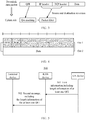
- FIG. 4 shows a format of an SDAP protocol data unit, where an RDI field, an RQI field, and a QFI field form a header of the SDAP protocol data unit.
- the RDI field is used to indicate whether an AS layer executes reflective mapping.
- the RQI field is used to indicate whether the NAS layer executes reflective QoS.
- a QFI in a current SDAP header is 6 bits in length. This indicates that one PDU session may include 0 to 63 QoS flows. The inventor finds that one PDU session may include even more QoS flows, so that the QFI length is greater than 6 bits.
- quantities of QoS flows included in different PDU sessions may vary greatly, and a quantity of QoS flows included in one PDU session may also dynamically change.
- the embodiments of this application provide a technical solution for data transmission of different QFI lengths.
- FIG. 5 shows a schematic flowchart of a method for configuring a QFI length according to an embodiment of this application. It should be understood that FIG. 5 is the schematic flowchart of the method for configuring the QFI length according to this embodiment of this application, and shows detailed communication steps or operations of the method. However, these steps or operations are merely examples. Other operations or variations of the operations in FIG. 5 may be further performed in this embodiment of this application. In addition, the steps in FIG. 5 may be separately performed in a sequence different from that shown in FIG. 5 , and not all the operations in FIG. 5 may be necessarily performed.
- the method 500 may be applied to a scenario in which a PDU session of a terminal device is established or updated shown in FIG. 2 .
- the procedure includes the following steps.
- a CN device sends a first message to a RAN device, where the first message includes length information of one or more QFIs.
- the CN device determines, based on a service requirement and/or a policy and charging control rule of the PDU session of the terminal device, a length of a QFI used to establish or modify the PDU session for the terminal device, and the CN device needs to notify the RAN device of the length information of the QFI by using signaling, so that the RAN device can correctly parse a data packet of a QoS flow received from the CN device and/or send, to the CN device, a data packet of a QoS flow that can be correctly parsed.
- the CN device sends the length information of the QFI used by the PDU session to the RAN device.
- a same QFI length is used for all QoS flows in the PDU session.
- one PDU session includes three QoS flows, where the three QoS flows are identified separately by using QFIs that are 6 bits in length.
- the CN device sends the length information of the plurality of QFIs used by the PDU session to the RAN device.
- different QFI lengths may be used for different QoS flows in the PDU session.
- one PDU session includes three QoS flows.
- a first QoS flow may be identified by using a QFI with a length of 6 bits
- a second QoS flow may be identified by using a QFI with a length of 8 bits
- a third QoS flow may be identified by using a QFI with a length of 10 bits.
- the first QoS flow and the second QoS flow may be identified by using QFIs with a length of 6 bits
- the third QoS flow may be identified by using a QFI with a length of 10 bits.
- the length information of the QFI may indicate the QFI length in a plurality of forms.
- the length information of the QFI may be a length value of the QFI.
- length information of one QFI is a length value of the QFI, such as 6 bits, 8 bits, or 10 bits.
- the length information of the QFI may be a value range of the QFI.
- length information of one QFI is a value range of the QFI, for example, 0 to 63 (the value range corresponds to a QFI length of 6 bits), 0 to 255 (the value range corresponds to a QFI length of 8 bits), or 0 to 1023 (the value range corresponds to a QFI length of 10 bits).
- the length information of the QFI may be a length class of the QFI.
- length information of one QFI is a length class of the QFI, such as a long QFI or a short QFI.
- a standard specifies or an operator defines different QFI lengths, such as 6 bits and 10 bits, that can be used by a network side and the terminal device.
- both the network side and the terminal device have obtained the information before the PDU session is established.
- the QFI length information sent by the CN device to the RAN device is a short QFI, it indicates that the QFI length used by the CN device is 6 bits.
- the QFI length information sent by the CN device to the RAN device is a long QFI, it indicates that the QFI length used by the CN device is 10 bits. Further, the CN device may perform indication by using a 1-bit field, for example, configure a bit value of the field as "0" to indicate that a short QFI is used, or configure a bit value of the field as "1" to indicate that a long QFI is used.
- the length class of the QFI may be a plurality of classes, for example, a long QFI, a medium QFI, and a short QFI.
- a standard specifies or an operator determines that three or more different QFI lengths, such as 6 bits, 8 bits and 10 bits, can be used by a network side and the terminal device.
- both the network side and the terminal device have obtained the information before the PDU session is established.
- the QFI length information sent by the CN device to the RAN device is a short QFI, it indicates that the QFI length used by the CN device is 6 bits.
- the QFI length information sent by the CN device to the RAN device is a medium QFI, it indicates that the QFI length used by the CN device is 8 bits.
- the QFI length information sent by the CN device to the RAN device is a long QFI, it indicates that the QFI length used by the CN device is 10 bits. Further, the CN device may perform indication by using a 2-bit field, for example, configure a bit value of the field as "00" to indicate that the short QFI is used, configure a bit value of the field as "01” to indicate that the medium QFI is used, or configure a bit value of the field as "10" to indicate that the long QFI is used.
- the QFI length information that is included in the first message is applied to both uplink transmission and downlink transmission of a QoS flow.
- the first message may separately include QFI length information of uplink transmission and QFI length information of downlink transmission of one QoS flow.
- the first message includes QFI length information of uplink transmission and QFI length information of downlink transmission of all QoS flows in the PDU session.
- the first message includes QFI length information of uplink transmission and QFI length information of downlink transmission of one or more QoS flows in the PDU session.
- the first message is used for the CN device to indicate the RAN device to establish or modify the PDU session for the terminal device.
- the first message may be a PDU session resource setup request (PDU session resource setup request) message, a PDU session resource modification request (PDU session resource modify request) message, an initial context setup request (initial context setup request) message, or the like.
- the RAN device sends a second message to the terminal device, where the second message includes the length information of the one or more QFIs.
- the RAN device obtains, from the CN device, the length of the QFI used in the PDU session of the terminal device, and the RAN device needs to notify the terminal device of the length information of the QFI by using signaling, so that the terminal device can correctly parse a DRB data packet that carries a QoS flow received from the RAN device and/or send, to the RAN device, a DRB data packet that carries a QoS flow and that can be correctly parsed.
- the RAN device sends the length information of one QFI to the terminal device.
- the QFI length information is for all QoS flows in the PDU session.
- the RAN device may further send the length information of a plurality of QFIs to the terminal device, where the length information of the plurality of QFIs is for different QoS flows.
- one piece of QFI length information sent by the RAN device to the terminal device may be for all QoS flows in one DRB.
- the QFI length information may also be represented in a plurality forms similar to those in step 501, for example, the QFI length value, the QFI value range, or the QFI length class.
- the QFI length information may be alternatively indicated by using another implicit method, for example, indirectly indicated by using other information.
- the RAN device notifies the terminal device of length information of an SDAP header.
- different QFI lengths are implicitly indicated. For example, when the length of the SDAP header is greater than 1 byte, it indicates that the QFI length is 8 bits. When the length of the SDAP header is less than or equal to 1 byte, it indicates that the QFI length is 6 bits.
- the QFI length information that is included in the second message may be applied to both uplink transmission and downlink transmission of one QoS flow at the same time, or applied to uplink transmission and downlink transmission of one QoS flow separately.
- the second message is used for the RAN device to establish or reconfigure an RRC connection for the terminal device.
- the second message may be an RRC connection re-establishment (RRC connection re-establishment) message, an RRC reconfiguration (RRC reconfiguration) message, an RRC connection resume (RRC connection resume) message, or the like.
- the length information of the one or more QFIs included in the second message may be carried in a DRB establishment or modification field that is in the second message, for example, carried in an SDAP configuration field of the DRB. Table 1 shows a way of carrying a QFI length in an SDAP configuration field.
- SDAP configuration field SDAP-Config :: SEQUENCE ⁇ pdu-Session PDU-SessionID, -FFS: separate configuration for UL and DL sdap-HeaderDL ENUMERATED ⁇ present, absent ⁇ , sdap-HeaderUL ENUMERATED ⁇ present, absent ⁇ , defaultDRB BOOLEAN, sdap-LengthInfo ENUMERATED ⁇ 8bit, 12bit,... ⁇
- the sdap-LengthInfo field is used to configure the length of the SDAP header. As shown in FIG. 4 , when a value of the field is 8 bits, it indicates that the QFI length is 6 bits. When the value of the field is 12 bits, it indicates that the QFI length is 10 bits. In this manner, the QFI length information is implicitly indicated by configuring the length of the SDAP header.
- a new field for example, a QFI-LegnthInfo field
- one PDU session in one SDAP configuration needs to include a plurality of pieces of QFI length information, and one piece of length information of a QFI corresponds to a DRB to which a QoS flow indicated by the QFI is mapped.
- the QFI length information may alternatively be for all QoS flows in one DRB. Different QFI length information may be configured for different DRBs in one PDU session, or same QFI length information may be configured for different DRBs in one PDU session.
- a CU-CP after obtaining the QFI length information from the CN device, a CU-CP notifies, by using signaling (for example, an SDAP configuration message), a CU-UP of QFI length information of a corresponding PDU session or DRB.
- signaling for example, an SDAP configuration message
- the terminal device may report, to the CN device by using NAS signaling, a capability of the terminal device to support QFIs of different lengths.
- the terminal device may further report, to the RAN device by using AS signaling, a capability of the terminal device to support QFIs of different lengths.
- the CN device may send, to the RAN device, the capability of the terminal device to support QFIs of different lengths, where the capability is obtained by the CN device.
- the RAN may also send, to the CN device, the capability of the terminal device to support QFIs of different lengths, where the capability is obtained by the RAN device.
- the RAN device may further report, to the CN device, a capability of the RAN device to support QFIs of different lengths, for example, by carrying a corresponding indication in an NG setup request (NG setup request) message, a RAN configuration update (RAN configuration update) message, an AMF configuration update acknowledge (AMF configuration update acknowledge) message, or an NG reset (NG reset) message.
- the RAN device may notify the CN device of a capability of the RAN device that the RAN device does not support a longer QFI (for example, does not support a QFI longer than 6 bits), for example, by carrying a corresponding indication in a cause (cause) field in an AMF configuration update failure/error indication (AMF configuration update failure/error indication) message.
- the CN device may further notify the RAN device of a capability of the CN device to support QFIs of different lengths, for example, by carrying a corresponding indication in an NG setup response (NG setup response) message, a RAN configuration update acknowledge (RAN configuration update acknowledge) message, an AMF configuration update (AMF configuration update) message, or an NG reset (NG reset) message.
- NG setup response NG setup response
- RAN configuration update acknowledge RAN configuration update acknowledge
- AMF configuration update AMF configuration update
- NG reset NG reset
- the CN device may notify the RAN device of a capability of the CN device that the CN device does not support a longer QFI (for example, does not support a QFI longer than 6 bits), for example, by carrying a corresponding indication in a cause (cause) field in an NG setup failure (NG setup failure) message or a RAN configuration update failure/error indication (RAN configuration update failure/error indication) message.
- the CN device learns the capability of the RAN device to support QFIs of different lengths and the capability of the terminal device to support QFIs of different lengths, to determine the length of the QFI used when the PDU session is established or modified for the terminal device.
- the CN device determines, based on a quantity of QoS flows of a PDU session, that a QFI with a length of 8 bits needs to be used, the RAN device supports a QFI with a maximum length of 10 bits, and the terminal device supports a QFI with a maximum length of 8 bits, so that the CN device determines to use a QFI with the length of 8 bits for the PDU session.
- the CN device determines, based on a quantity of QoS flows of a PDU session, that a QFI with a length of 8 bits needs to be used, the RAN device supports a QFI with a maximum length of 10 bits, while the terminal device supports a QFI with a maximum length of 6 bits, so that the CN device determines to use a QFI with the length of 6 bits for the PDU session.
- the length of the QFI used when data is transmitted between the terminal device and the RAN device, and between the RAN device and the CN device is determined.
- an RRC layer or an SDAP layer of the terminal device may notify a PDCP layer of a QFI length of a corresponding PDU session, so that the PDCP layer knows content on which encryption/decryption and header compression/header decompression are performed.
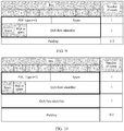
- each device encapsulates a data packet based on a determined QFI length. For example, for downlink transmission, downlink data of a QoS flow sent by the CN device to the RAN device on an NG-U tunnel is encapsulated by using a GPRS tunneling protocol-user plane (GPRS Tunneling Protocol-User Plane, GTP-U). After receiving a downlink data packet from the CN device, the RAN device encapsulates the data packet at the SDAP layer.
- FIG. 6 shows several possible forms of an SDAP header at an SDAP layer. Assume that it is determined through the foregoing steps that the length of the QFI is 8 bits. In form (a), a QFI field occupies 8 bits, and is followed by Data.
- a QFI field occupies 8 bits, followed by a reserved field (R) with a length of 6 bits, and then followed by Data.
- R reserved field
- a 6-bit reserved field (R) is padded before a QFI field, so that the QFI field starts from an integral byte, for example, the QFI field starts from a first bit of the second byte (Oct2) shown in the figure.
- form (d) may be used.
- a length indicator (length indicator, LI) field is added before a QFI field to indicate the length of the QFI.
- a T-PDU corresponds to service data (such as IP data), and a Next Extension Header Type field in a GTPv1-U header (for a specific format, refer to Table 2) may indicate that a content of a next header is an extension header of a PDU session container (container).
- a format of the extension header of the PDU session container is shown in Table 3.
- the PDU session container includes QFI information.
- FIG. 9 shows a format of a PDU session container when a QFI length is 6 bits.
- This embodiment of this application provides a way of enhancing the PDU session container to adapt to QFIs of different lengths. For example, some bit information is added to the format of the PDU session container to distinguish QFIs of different lengths.
- a PDU type field based on an extended PDU type value in the PDU session container, there are different values for a PDU type field to correspond to QFIs of different lengths. For example, if the PDU type value is 0, it indicates that the QFI length is 6 bits. If the PDU type value is 1, it indicates that the QFI length is 10 bits.
- FIG. 1 shows a format of a PDU session container when a QFI length is 6 bits.
- FIG. 10 shows a format of an enhanced PDU session container, where the PDU type value is 2 and a QFI length is 14 bits.
- information for indicating a QFI length is added to a spare (Spare) field of the PDU session container.
- FIG. 11 shows a format of another enhanced PDU container, where four bits occupied by a spare field are used to indicate a QFI length. It should be understood that a QFI length indication may also be represented by using another quantity of bits in the spare field.
- an extended PDU type value in the PDU session container is retained. For example, the value is still 0, and a spare (Spare) field in FIG.
- a low-order bit of the QFI corresponds to a bit occupied by an existing QFI field in FIG. 8 .
- the QFI length is 10 bits
- 4 high-order bits correspond to bits occupied by the first byte spare in FIG. 8
- 6 low-order bits are corresponding to bits occupied by QoS Flow Identifier in FIG. 8 .
- the QFI value is 1111100000
- 4 high-order bits are 1111, corresponding to the bits occupied by the first byte spare in FIG. 8
- 6 low-order bits are 100000, corresponding to the bits occupied by the QoS Flow Identifier field in FIG. 8 .
- the CN device can determine, based on a service requirement and/or a policy and charging control rule of the PDU session, a QFI length, and notify the RAN device and the terminal of the QFI length, so that a QFI field of an appropriate length is carried during data transmission between the CN device and the RAN device and between the RAN device and the terminal device. This avoids resource waste, and improves data transmission efficiency.
- a quantity of QoS flows included in the PDU session may change.
- the PDU session may include hundreds of QoS flows, and QFIs with a relatively long bit length (for example, a length of 10 bits) needs to be used.
- QFIs with a relatively long bit length for example, a length of 10 bits
- a quantity of QoS flows in the PDU session gradually decreases to dozens of QoS flows. Then, only QFIs of a relatively short bit length (for example, a length of 6 bits) need to be used.
- a CN device, a RAN device, and the terminal device need to update the QFI length, and map a QFI of a current QoS flow from a previous QFI of a first length to an updated QFI of a second length.
- FIG. 8 shows a schematic flowchart of a method for updating a QFI length according to an embodiment of this application.
- FIG. 8 is the schematic flowchart of the method for configuring the QFI length according to this embodiment of this application, and shows detailed communication steps or operations of the method.
- these steps or operations are merely examples. Other operations or variations of the operations in FIG. 8 may be further performed in this embodiment of this application.
- the steps in FIG. 8 may be separately performed in a sequence different from that shown in FIG. 8 , and not all the operations in FIG. 8 may be necessarily performed.
- the method 800 may be applied to a scenario in which a PDU session of a terminal device is updated shown in FIG. 2 .
- the procedure includes the following steps.
- a CN device sends a third message to a RAN device, where the third message includes a mapping relationship of one or more QFIs.
- the CN device determines, based on a change of a service requirement and/or a policy and charging control rule of a PDU session of a terminal device, that a length of a QFI used for the PDU session established for the terminal device needs to change, for example, from a length of 10 bits to a length of 6 bits.
- the CN device For a QoS flow in the PDU session, the CN device needs to update a QFI of a first length previously used for the QoS flow to a QFI of a second length, and to notify the RAN device of a mapping relationship between the previous QFI of the first length and the updated QFI of the second length by using signaling, so that the RAN device can correctly parse a data packet of the QoS flow received from the CN device.
- a previous QFI length of the QoS flow is 10 bits, and a value of the previous QFI length is "1001011101".
- the CN device After the CN device determines to update the QFI length to 6 bits and configure an updated QFI of the QoS flow as "101001", the CN device needs to notify the RAN device of a mapping relationship between the previous QFI of a first length and the updated QFI of a second length of the QoS flow, namely, the mapping relationship from "1001011101" to "101001". It should be understood that when the PDU session includes a plurality of QoS flows, the third message includes a mapping relationship between a plurality of QFIs corresponding to the plurality of QoS flows. Previous QFIs of the QoS flows may have a same length or different lengths, and updated QFIs may have a same length or different lengths.
- the CN device may further map a plurality of QoS flows before the update to one updated QoS flow, or map one QoS flow before the update to a plurality of updated QoS flows.
- the CN device maps a plurality of QFIs of a length of 10 bits to one QFI of a length of 6 bits.
- the CN device maps one QFI of a length of 10 bits to a plurality of QFIs of a length of 6 bits.
- the third message further includes length information of one or more QFIs.
- the mapping relationship of the one or more QFIs are applied to one or more established QoS flows.
- the length information of the one or more QFIs is applied to one or more new QoS flows that need to be established. Further, an implementation of the length information of the one or more QFIs is similar to the description in step 501. Details are not described herein again.
- the QFI mapping relationship that is included in the third message may be applied to both uplink transmission and downlink transmission of the QoS flow at the same time, or applied to uplink transmission and downlink transmission separately.
- the QFI length information that is included in the third message may be applied to both uplink transmission and downlink transmission of the QoS flow at the same time, or applied to uplink transmission and downlink transmission of the QoS flow separately.
- the third message is used for the CN device to indicate the RAN device to modify the PDU session for the terminal device.
- the third message may be a PDU session resource modification request (PDU session resource modify request) message, or the like.
- the RAN device sends a fourth message to the terminal device, where the fourth message includes the mapping relationship of the one or more QFIs.
- the RAN device obtains, from the CN device, the QFI mapping relationship of the one or more QoS flows of the terminal device, and the RAN device needs to notify the terminal device of the QFI mapping relationship of the one or more QoS flows by using signaling, so that the terminal device can correctly parse a DRB data packet that carries a QoS flow received from the RAN device and/or send, to the RAN device, a DRB data packet that carries a QoS flow and that can be correctly parsed.
- the RAN device Similar to the implementation in step 801, for a QoS flow, the RAN device notifies the terminal device of a mapping relationship between a previous QFI of a first length and an updated QFI of a second length of the QoS flow by using signaling.
- the fourth message includes the length information of the one or more QFIs.
- the length information of the one or more QFIs is applied to one or more new QoS flows that need to be established.
- the fourth message is used for the RAN device to reconfigure an RRC connection for the terminal device.
- the fourth message may be an RRC reconfiguration (RRC reconfiguration) message, an RRC connection resume (RRC connection resume) message, or the like.
- a CU-CP after obtaining the QFI mapping relationship from the CN device, notifies, by using signaling (for example, an SDAP configuration message), a CU-UP of QFI mapping relationship of a corresponding QoS flow.
- signaling for example, an SDAP configuration message
- the QFI with the updated length is determined to be used when data is transmitted between the terminal device and the RAN device, and between the RAN device and the CN device.
- an RRC layer or an SDAP layer of the terminal device may notify a PDCP layer of the updated QFI length of each QoS flow of a corresponding PDU session, so that the PDCP layer knows content on which encryption/decryption and header compression/header decompression are performed.
- the CN device can determine, based on a change of a service requirement and/or a policy and charging control rule of the PDU session, the updated QFI length, and notify the RAN device and the terminal device of the mapping relationship between the previous QFI and the updated QFI of each QoS flow, so that the updated QFI is carried during data transmission between the CN device and the RAN device, and between the RAN device and the terminal device. In this way, continuity of data transmission is maintained.
- each device encapsulates a data packet based on the updated QFI of each QoS flow. For example, for downlink data transmission of a QoS flow, a GTP-U format corresponding to an updated QFI length is used for downlink data of the QoS flow sent by the CN device to the RAN device on an NG-U tunnel.
- the RAN device For downlink transmission of the QoS flow between the RAN device and the terminal device, in a possible implementation, after determining that downlink data of the QoS flow that uses a previous QFI of a first length has been correctly received by the terminal device, the RAN device sends a fourth message to notify the terminal device, and continues to transmit the downlink data of the QoS flow by using a QFI of a second length.
- a mapping relationship between the QoS flow and a DRB remains unchanged. In other words, the QoS flow is mapped to a same DRB regardless of whether the previous QFI of the first length or the updated QFI of the second length is used.
- the RAN device configures, in the fourth message, a new second DRB for the QoS flow for which the QFI is updated to the second length, and reserves a first DRB to which the QoS flow that uses the previous QFI of the first length is mapped.
- the mapping relationship between the QoS flow and the DRB changes.
- the QoS flow is mapped to one DRB when the previous QFI of the first length is used, and is mapped to another DRB when the updated QFI of the second length is used.
- the RAN device sends an end indication on a first DRB, and continues to transmit the downlink data of the QoS flow on a second DRB.
- the terminal device may add, based on a correspondence of the QFI in the fourth message, the updated QFI of the second length to the data packet when an SDAP layer of the terminal device submits the data packet to an upper layer (for example, an application layer).
- an SDAP layer of the terminal device submits the data packet to an upper layer (for example, an application layer).
- an upper layer for example, an application layer.
- the end indication may be indicated by using a control PDU at the SDAP layer, or may be indicated by using a PDU without a data packet at the SDAP layer, or may be indicated by using a control PDU at the PDCP layer.
- the control PDU at the SDAP layer may further carry the previous QFI of the first length, or the PDU without the data packet may further carry the previous QFI of the first length.
- the RRC layer of the terminal device may notify an upper layer (for example, an application layer) of the update of the corresponding QFI, and the RRC layer of the terminal device may also notify the SDAP layer of the update of the corresponding QFI.
- an upper layer for example, an application layer
- the SDAP layer of the terminal device sends one end indication on the first DRB, and continues to transmit uplink data of the QoS flow on the second DRB.
- the end indication may be indicated by using a control PDU at the SDAP layer, or may be indicated by using a PDU without a data packet at the SDAP layer, or may be indicated by using a control PDU at the PDCP layer.
- the control PDU at the SDAP layer may further carry the previous QFI of the first length, or the PDU without the data packet may further carry the previous QFI of the first length.
- the RAN device when the RAN device receives an uplink data packet on the first DRB, the RAN device sends, based on the third message sent by the CN device, the data packet on the NG-U tunnel to the CN device in the GTP-U format that corresponds to the updated QFI.
- FIG. 12 is a schematic block diagram of a communication apparatus 1200 according to an embodiment of this application.
- the communication apparatus 1200 may correspond to (for example, may be configured on or may be) the terminal device described in the foregoing method embodiments.
- the communication apparatus 1200 may include a processor 1201 and a transceiver 1202. The processor and the transceiver are communicatively connected.
- the communication apparatus 1200 further includes a memory 1203.
- the memory 1203 is communicatively connected to the processor 1201.
- the processor 1201, the memory 1203, and the transceiver 1202 may be communicatively connected.
- the memory 1203 may be configured to store an instruction.
- the processor 1201 is configured to execute the instruction stored in the memory, to control the transceiver 1202 to send information or a signal.
- the processor 1201 and the transceiver 1202 are separately configured to perform actions or processing processes performed by the terminal device in the foregoing method embodiments. Herein, to avoid repetition, detailed descriptions thereof are omitted.
- FIG. 13 is a schematic block diagram of a communication apparatus 1300 according to an embodiment of this application.
- the communication apparatus 1300 may correspond to (for example, may be configured on or may be) the terminal device described in the foregoing method embodiments.
- the communication apparatus 1300 may include a receiving module 1301, a processing module 1302, and a sending module 1303.
- the processing module 1302 is in communication connection with the receiving module 1301 and the sending module 1303.
- the modules or units in the communication device 1300 are separately configured to perform actions or processing processes performed by the terminal device in the foregoing method embodiments.
- detailed descriptions thereof are omitted.
- FIG. 14 is a schematic block diagram of a communication apparatus 1400 according to an embodiment of this application.
- the communication apparatus 1400 may correspond to (for example, may be configured on or may be) the RAN device described in the foregoing method embodiments.
- the communication apparatus 1400 may include a processor 1401 and a transceiver 1402. The processor and the transceiver are communicatively connected.
- the communication apparatus 1400 further includes a memory 1403.
- the memory 1403 is communicatively connected to the processor 1401.
- the processor 1401, the memory 1403, and the transceiver 1402 may be communicatively connected.
- the memory may be configured to store an instruction.
- the processor is configured to execute the instruction stored in the memory, to control the transceiver to 702 send information or a signal.
- the processor 701 and the transceiver 702 are separately configured to perform actions or processing processes performed by the RAN device in the foregoing method embodiments. Herein, to avoid repetition, detailed descriptions thereof are omitted.
- FIG. 15 is a schematic block diagram of a communication apparatus 1500 according to an embodiment of this application.
- the communication apparatus 1500 may correspond to (for example, may be configured on or may be) the RAN device described in the foregoing method embodiments.
- the communication apparatus 1500 may include a receiving module 1501, a processing module 1502, and a sending module 1503.
- the processing module 1502 is in communication connection with the receiving module 1501 and the sending module 1503.
- the modules or units in the communication device 1500 are separately configured to perform actions or processing processes performed by the RAN device in the foregoing method embodiments.
- detailed descriptions thereof are omitted.
- FIG. 16 is a schematic block diagram of a communication apparatus 1600 according to an embodiment of this application.
- the communication apparatus 1600 may correspond to (for example, may be configured on or may be) the CN device described in the foregoing method embodiments.
- the communication apparatus 1600 may include a processor 1601 and a transceiver 1602. The processor and the transceiver are communicatively connected.
- the communication apparatus 1600 further includes a memory 1603.
- the memory 1603 is communicatively connected to the processor 1601.
- the processor 1601, the memory 1603, and the transceiver 1602 may be communicatively connected.
- the memory 1603 may be configured to store an instruction.
- the processor 1601 is configured to execute the instruction stored in the memory, to control the transceiver 702 to send information or a signal.
- the processor 701 and the transceiver 702 are separately configured to perform actions or processing processes performed by the CN device in the foregoing method embodiments. Herein, to avoid repetition, detailed descriptions thereof are omitted.
- FIG. 17 is a schematic block diagram of a communication apparatus 1700 according to an embodiment of this application.
- the communication apparatus 1700 may correspond to (for example, may be configured on or may be) the CN device described in the foregoing method embodiments.
- the communication apparatus 1700 may include a receiving module 1701, a processing module 1702, and a sending module 1703.
- the processing module 1702 is in communication connection with the receiving module 1701 and the sending module 1703.
- the modules or units in the communication device 1700 are separately configured to perform actions or processing processes performed by the CN device in the foregoing method embodiments.
- detailed descriptions thereof are omitted.
- processors (1201, 1401, and 1601) in the apparatus embodiments of this application may be a central processing unit (Central Processing Unit, CPU for short), a network processor (Network Processor, NP for short), a hardware chip, or any combination thereof.
- the hardware chip may be an application-specific integrated circuit (Application-Specific Integrated Circuit, ASIC for short), a programmable logic device (Programmable Logic Device, PLD for short), or a combination thereof.
- the PLD may be a complex programmable logic device (Complex Programmable Logic Device, CPLD for short), a field-programmable logic gate array (Field-Programmable Gate Array, FPGA for short), generic array logic (Generic Array Logic, GAL for short), or any combination thereof.
- CPLD Complex Programmable Logic Device
- FPGA Field-Programmable Gate Array
- GAL Generic Array Logic
- the memories (1203, 1403 and 1603) in the apparatus embodiments of this application may be a volatile memory (Volatile Memory) such as a random-access memory (Random-Access Memory, RAM for short); or may be a nonvolatile memory (Non-Volatile Memory) such as a read-only memory (Read-Only Memory, ROM for short), a flash memory (Flash Memory), a hard disk drive (Hard Disk Drive, HDD for short), or a solid-state drive (Solid-State Drive, SSD for short); or may be a combination of the foregoing types of memories.
- volatile memory such as a random-access memory (Random-Access Memory, RAM for short
- Non-Volatile Memory such as a read-only memory (Read-Only Memory, ROM for short), a flash memory (Flash Memory), a hard disk drive (Hard Disk Drive, HDD for short), or a solid-state drive (Solid-State Drive, SSD for short
- SSD solid-state drive
- the disclosed apparatus and method may be implemented in other manners.
- the described apparatus embodiment is merely an example.
- the unit division is merely logical function division and may be other division in actual implementation.
- a plurality of units or components may be combined or integrated into another system, or some features may be ignored or not performed.
- the displayed or discussed mutual couplings or direct couplings or communication connections may be implemented by using some interfaces.
- the indirect couplings or communication connections between the apparatuses or units may be implemented in electronic, mechanical, or other forms.
- the units described as separate parts may or may not be physically separate, and parts displayed as units may or may not be physical units, may be located in one position, or may be distributed on a plurality of network units. Some or all of the units may be selected based on actual requirements to achieve the objectives of the solutions of the embodiments.
- functional units in the embodiments of this application may be integrated into one processing unit, or each of the units may exist alone physically, or two or more units are integrated into one unit.
- the integrated unit may be implemented in a form of hardware, or may be implemented in a form of a software functional unit.
- the functions When functions are implemented in the form of a software functional unit and sold or used as an independent product, the functions may be stored in a computer-readable storage medium. Based on such an understanding, the technical solutions of this application essentially, or the part contributing to the prior art, or some of the technical solutions may be implemented in a form of a software product.
- the software product is stored in a storage medium, and includes several instructions for instructing a computer device (which may be a personal computer, a server, or a network device) to perform all or some of the steps of the methods described in the embodiments of this application.
- the foregoing storage medium includes: any medium that can store program code, such as a USB flash drive, a removable hard disk, a read-only memory (ROM, Read-Only Memory), a random access memory (RAM, Random Access Memory), a magnetic disk, or an optical disc.
- program code such as a USB flash drive, a removable hard disk, a read-only memory (ROM, Read-Only Memory), a random access memory (RAM, Random Access Memory), a magnetic disk, or an optical disc.
Landscapes
- Engineering & Computer Science (AREA)
- Computer Networks & Wireless Communication (AREA)
- Signal Processing (AREA)
- Quality & Reliability (AREA)
- Computer Security & Cryptography (AREA)
- Mobile Radio Communication Systems (AREA)
Applications Claiming Priority (2)
| Application Number | Priority Date | Filing Date | Title |
|---|---|---|---|
| CN201810653954.0A CN110636544B (zh) | 2018-06-22 | 2018-06-22 | 一种数据传输方法及装置 |
| PCT/CN2019/092193 WO2019242714A1 (fr) | 2018-06-22 | 2019-06-21 | Procédé et appareil de transmission de données |
Publications (2)
| Publication Number | Publication Date |
|---|---|
| EP3806529A1 true EP3806529A1 (fr) | 2021-04-14 |
| EP3806529A4 EP3806529A4 (fr) | 2021-07-28 |
Family
ID=68967956
Family Applications (1)
| Application Number | Title | Priority Date | Filing Date |
|---|---|---|---|
| EP19823093.0A Pending EP3806529A4 (fr) | 2018-06-22 | 2019-06-21 | Procédé et appareil de transmission de données |
Country Status (4)
| Country | Link |
|---|---|
| US (1) | US11877178B2 (fr) |
| EP (1) | EP3806529A4 (fr) |
| CN (1) | CN110636544B (fr) |
| WO (1) | WO2019242714A1 (fr) |
Families Citing this family (16)
| Publication number | Priority date | Publication date | Assignee | Title |
|---|---|---|---|---|
| US12538144B2 (en) * | 2018-10-31 | 2026-01-27 | Apple Inc. | Performance measurements related to PDU session and N4 session management |
| US10785674B2 (en) * | 2019-01-23 | 2020-09-22 | Verizon Patent And Licensing, Inc. | Allocation of data radio bearers for quality of service flows |
| US11902830B2 (en) * | 2019-02-12 | 2024-02-13 | Lg Electronics Inc. | Method and apparatus for processing data unit in wireless communication system |
| WO2020204522A1 (fr) * | 2019-03-29 | 2020-10-08 | 삼성전자 주식회사 | Procédé et dispositif de gestion de qos utilisant un protocole nas |
| CN113938904B (zh) * | 2020-06-29 | 2024-09-24 | 华为技术有限公司 | 数据传输的方法和装置 |
| WO2022036604A1 (fr) * | 2020-08-19 | 2022-02-24 | 华为技术有限公司 | Procédé et appareil de transmission de données |
| CN114205225B (zh) * | 2020-08-26 | 2025-07-15 | 华为技术有限公司 | 一种配置错误信息传输方法及设备 |
| CN112804716B (zh) * | 2020-12-29 | 2023-04-28 | 联想未来通信科技(重庆)有限公司 | 一种数据限值的配置方法、装置及存储介质 |
| CN118555607A (zh) * | 2021-01-04 | 2024-08-27 | 腾讯科技(深圳)有限公司 | 数据传输方法、装置、计算机可读介质及电子设备 |
| US12439291B2 (en) * | 2021-09-02 | 2025-10-07 | Apple Inc. | Quality of service framework enhancements for 5G service |
| CN114158074B (zh) * | 2021-11-29 | 2024-03-29 | 北京恒安嘉新安全技术有限公司 | 一种5g网元地址确定方法、装置、电子设备及存储介质 |
| CN115884417A (zh) * | 2021-12-31 | 2023-03-31 | 中兴通讯股份有限公司 | 参数配置方法、通信设备和存储介质 |
| CN116567657B (zh) * | 2022-01-28 | 2025-12-12 | 腾讯科技(深圳)有限公司 | 数据传输方法、装置、计算机可读介质及电子设备 |
| WO2024250225A1 (fr) * | 2023-06-08 | 2024-12-12 | Huawei Technologies Co., Ltd. | Procédés et systèmes de sélection de fonction de gestion |
| CN121890155A (zh) * | 2023-09-29 | 2026-04-17 | 华为技术有限公司 | 用于任务会话的通信方法、装置和系统 |
| CN119341691B (zh) * | 2024-10-16 | 2026-01-20 | 中国移动通信有限公司研究院 | 数据传输方法、装置、电子设备、芯片、存储介质及计算机程序产品 |
Family Cites Families (12)
| Publication number | Priority date | Publication date | Assignee | Title |
|---|---|---|---|---|
| US10142889B2 (en) * | 2016-05-13 | 2018-11-27 | Huawei Technologies Co., Ltd. | Method and system for providing guaranteed quality of service and quality of experience channel |
| US10911977B2 (en) * | 2016-08-01 | 2021-02-02 | Samsung Electronics Co., Ltd. | Method and apparatus for managing data communication in wireless communication network |
| CN107637123B (zh) * | 2017-04-27 | 2020-12-04 | 北京小米移动软件有限公司 | 信息传递方法、装置及计算机可读存储介质 |
| CN107493590B (zh) * | 2017-06-15 | 2021-08-03 | 苏州智行畅联科技有限公司 | 数据传输方法及装置、基站及计算机可读存储介质 |
| CN109451828B (zh) * | 2017-07-25 | 2022-05-10 | 北京小米移动软件有限公司 | 下行数据包配置方法及装置 |
| CN109392024B (zh) * | 2017-08-11 | 2021-06-15 | 华为技术有限公司 | 一种业务质量流的控制方法及相关设备 |
| JP7145603B2 (ja) * | 2017-11-15 | 2022-10-03 | シャープ株式会社 | 端末装置、基地局装置および方法 |
| CN109716817A (zh) * | 2018-02-06 | 2019-05-03 | Oppo广东移动通信有限公司 | 数据传输控制方法及相关产品 |
| WO2019153207A1 (fr) * | 2018-02-08 | 2019-08-15 | Oppo广东移动通信有限公司 | Procédé d'indication dynamique d'un qfi et équipement utilisateur |
| WO2019153272A1 (fr) * | 2018-02-09 | 2019-08-15 | Oppo广东移动通信有限公司 | Procédé et dispositif basés sur la qualité de service pour une transmission de données |
| AR114964A1 (es) * | 2018-02-15 | 2020-11-11 | Ericsson Telefon Ab L M | Métodos que proporcionan armonización qfi entre ran y 5gc y terminales inalámbricos, estaciones base, y nodos de red central relacionados |
| US20210127295A1 (en) * | 2018-05-09 | 2021-04-29 | Lg Electronics Inc. | Method and apparatus for transmitting packet based on type of packet by transmission end in wireless communication system |
-
2018
- 2018-06-22 CN CN201810653954.0A patent/CN110636544B/zh active Active
-
2019
- 2019-06-21 WO PCT/CN2019/092193 patent/WO2019242714A1/fr not_active Ceased
- 2019-06-21 EP EP19823093.0A patent/EP3806529A4/fr active Pending
-
2020
- 2020-12-17 US US17/124,650 patent/US11877178B2/en active Active
Also Published As
| Publication number | Publication date |
|---|---|
| US20210105657A1 (en) | 2021-04-08 |
| US11877178B2 (en) | 2024-01-16 |
| WO2019242714A1 (fr) | 2019-12-26 |
| CN110636544B (zh) | 2022-09-23 |
| CN110636544A (zh) | 2019-12-31 |
| EP3806529A4 (fr) | 2021-07-28 |
Similar Documents
| Publication | Publication Date | Title |
|---|---|---|
| US11877178B2 (en) | Data transmission method and apparatus | |
| US11647557B2 (en) | Radio access network node, radio terminal, and methods therefor | |
| CN110383915B (zh) | 无线接入网节点、无线终端及其方法和非瞬时性计算机可读介质 | |
| US11457392B2 (en) | Handover method and apparatus | |
| CN110505714B (zh) | 多链接通信方法、设备和终端 | |
| JP2020523955A (ja) | 通信方法および装置ならびに無線アクセス・ネットワーク | |
| US10701591B2 (en) | Data transmission method, apparatus, and system |
Legal Events
| Date | Code | Title | Description |
|---|---|---|---|
| STAA | Information on the status of an ep patent application or granted ep patent |
Free format text: STATUS: THE INTERNATIONAL PUBLICATION HAS BEEN MADE |
|
| PUAI | Public reference made under article 153(3) epc to a published international application that has entered the european phase |
Free format text: ORIGINAL CODE: 0009012 |
|
| STAA | Information on the status of an ep patent application or granted ep patent |
Free format text: STATUS: REQUEST FOR EXAMINATION WAS MADE |
|
| 17P | Request for examination filed |
Effective date: 20210107 |
|
| AK | Designated contracting states |
Kind code of ref document: A1 Designated state(s): AL AT BE BG CH CY CZ DE DK EE ES FI FR GB GR HR HU IE IS IT LI LT LU LV MC MK MT NL NO PL PT RO RS SE SI SK SM TR |
|
| AX | Request for extension of the european patent |
Extension state: BA ME |
|
| A4 | Supplementary search report drawn up and despatched |
Effective date: 20210625 |
|
| RIC1 | Information provided on ipc code assigned before grant |
Ipc: H04W 28/02 20090101AFI20210621BHEP |
|
| DAV | Request for validation of the european patent (deleted) | ||
| DAX | Request for extension of the european patent (deleted) | ||
| STAA | Information on the status of an ep patent application or granted ep patent |
Free format text: STATUS: EXAMINATION IS IN PROGRESS |
|
| 17Q | First examination report despatched |
Effective date: 20230314 |