EP3806582B1 - Dispositif formant appareil électroménager - Google Patents
Dispositif formant appareil électroménager Download PDFInfo
- Publication number
- EP3806582B1 EP3806582B1 EP20199653.5A EP20199653A EP3806582B1 EP 3806582 B1 EP3806582 B1 EP 3806582B1 EP 20199653 A EP20199653 A EP 20199653A EP 3806582 B1 EP3806582 B1 EP 3806582B1
- Authority
- EP
- European Patent Office
- Prior art keywords
- cooling channel
- unit
- household appliance
- cooling
- advantageously
- Prior art date
- Legal status (The legal status is an assumption and is not a legal conclusion. Google has not performed a legal analysis and makes no representation as to the accuracy of the status listed.)
- Active
Links
Images


Classifications
-
- H—ELECTRICITY
- H05—ELECTRIC TECHNIQUES NOT OTHERWISE PROVIDED FOR
- H05B—ELECTRIC HEATING; ELECTRIC LIGHT SOURCES NOT OTHERWISE PROVIDED FOR; CIRCUIT ARRANGEMENTS FOR ELECTRIC LIGHT SOURCES, IN GENERAL
- H05B6/00—Heating by electric, magnetic or electromagnetic fields
- H05B6/02—Induction heating
- H05B6/10—Induction heating apparatus, other than furnaces, for specific applications
- H05B6/12—Cooking devices
- H05B6/1209—Cooking devices induction cooking plates or the like and devices to be used in combination with them
- H05B6/1245—Cooking devices induction cooking plates or the like and devices to be used in combination with them with special coil arrangements
- H05B6/1263—Cooking devices induction cooking plates or the like and devices to be used in combination with them with special coil arrangements using coil cooling arrangements
-
- F—MECHANICAL ENGINEERING; LIGHTING; HEATING; WEAPONS; BLASTING
- F24—HEATING; RANGES; VENTILATING
- F24C—DOMESTIC STOVES OR RANGES ; DETAILS OF DOMESTIC STOVES OR RANGES, OF GENERAL APPLICATION
- F24C15/00—Details
- F24C15/006—Arrangements for circulation of cooling air
-
- F—MECHANICAL ENGINEERING; LIGHTING; HEATING; WEAPONS; BLASTING
- F24—HEATING; RANGES; VENTILATING
- F24C—DOMESTIC STOVES OR RANGES ; DETAILS OF DOMESTIC STOVES OR RANGES, OF GENERAL APPLICATION
- F24C15/00—Details
- F24C15/10—Tops, e.g. hot plates; Rings
- F24C15/101—Tops, e.g. hot plates; Rings provisions for circulation of air
Definitions
- the invention relates to a household appliance device according to the preamble of claim 1 and a method for operating a household appliance device according to the preamble of claim 11.
- a household appliance designed as a hob is already known from the prior art, which has a heat sink.
- the heat sink has a cooling channel and, in an operating state, cools an electronic unit by means of the cooling channel.
- the hob has a fan unit, which, in an operating state, provides a fluid flow for the heat sink.
- the fan unit is arranged at a first end of the cooling channel with respect to a longitudinal direction of the cooling channel and blows the fluid flow into the cooling channel parallel to the longitudinal direction of the cooling channel.
- the fluid flow flows in the longitudinal direction of the cooling channel from the first end of the cooling channel to a second end of the cooling channel opposite the first end in the longitudinal direction through the cooling channel.
- EP 2 679 913 A2 , EP 2 292 979 A1 and JP2 890415 B2 disclose a household appliance device according to the preamble of claim 1.
- the object of the invention is in particular, but not limited to, providing a generic device with improved properties with regard to cooling.
- the object is achieved according to the invention by the features of claims 1 and 11, while advantageous embodiments and further developments of the invention can be found in the subclaims.
- the invention is based on a household appliance device according to claim 1.
- cooling properties can be optimized and/or improved, particularly at the same and advantageously lower costs, which in particular makes it possible to achieve a high level of operating comfort.
- the fluid flow directed laterally to the longitudinal direction of the cooling channel can advantageously enable direct cooling of the electronic unit by means of the fluid flow, in particular in addition to cooling the electronic unit by means of the cooling channel, since this could in particular be directed at least partially in the direction of the electronic unit, whereby particularly advantageous cooling properties can be provided.
- improved cooling properties expensive electronic components of the electronic unit could be replaced by cheaper ones, whereby, for example, a cost-effective design could be achieved.
- a “household appliance device”, in particular a “cooking appliance device”, advantageously an “induction cooking appliance device”, particularly advantageously a “hob device” and preferably an “induction hob device” is to be understood as at least one part, in particular a subassembly, of a household appliance, in particular a cooking appliance, advantageously an induction cooking appliance, particularly advantageously a hob and preferably an induction hob.
- a household appliance having the household appliance device could be a refrigeration appliance, such as a freezer and advantageously a refrigerator and/or freezer.
- a household appliance having the household appliance device could, in particular alternatively or additionally, be, for example, a cleaning appliance, such as a dishwasher and/or a washing machine and/or a dryer.
- a household appliance having the household appliance device is advantageously a cooking appliance and advantageously an induction cooking appliance.
- a household appliance designed as a cooking appliance could be, for example, an oven and/or a microwave and/or a grill and/or a steamer.
- the oven could be, for example, an oven, in particular an induction oven, and/or a stove, in particular an induction stove.
- a household appliance designed as a cooking appliance is advantageously a hob and preferably an induction hob.
- a "heat sink” is to be understood in particular as a unit which, in an operating state, protects at least one structural unit to be cooled from overheating and/or dissipates heat from at least one structural unit to be cooled, in particular in an increased manner.
- the heat sink has in particular at least one cooling fin and/or at least one cooling lamella, advantageously several cooling fins and/or several cooling lamellas, through which the fluid flow flows in particular in an operating state.
- the heat sink in particular by means of the cooling fin and/or the cooling lamella, advantageously by means of the cooling fins and/or the cooling lamellas, provides an enlarged surface, in particular in order to improve the cooling performance of the heat sink and/or to enable increased heat dissipation of the structural unit to be cooled.
- the heat sink in particular keeps a temperature of the structural unit to be cooled, in particular at least substantially constant and advantageously constant.
- the heat sink has at least one cooling surface which, in an operating state, at least partially contacts the structural unit to be cooled and, in particular, in an operating state, absorbs energy, in particular in the form of heat, from the structural unit to be cooled and/or extracts energy from the structural unit to be cooled.
- the component to be cooled could, for example, have at least one inverter and/or at least one rectifier and/or at least one diode and/or at least one diode circuit.
- the component to be cooled could be a unit which tends to, in particular increased, heating and/or overheating in an operating state and/or is intended to do so.
- the component to be cooled is in particular an electrical and/or electronic unit.
- the electronic unit has the component to be cooled.
- the household appliance device has in particular at least one and advantageously at least the electronic unit.
- the electronic unit is in particular an electrical and/or electronic unit.
- the electronic unit could at least participate in at least one device function and/or advantageously in at least one main device function in an operating state.
- the device function and/or the main device function could, for example, include at least one cold function, such as a cooling function and/or a freezing function, and/or at least one cleaning function.
- the device function and/or the main device function could include at least one cooking function and/or at least one heating function.
- the heat sink cools the cooling unit in an operating state, in particular by means of the cooling channel.
- the heat sink could in particular define and/or delimit and/or form the cooling channel.
- the cooling channel is designed as a spatial region that is at least partially surrounded and/or enclosed by the heat sink.
- the heat sink could advantageously form and/or define and/or provide at least one outer boundary of the cooling channel.
- the heat sink could surround and/or enclose the cooling channel perpendicular to the longitudinal direction of the cooling channel, in particular at least in sections and for example at least substantially.
- the heat sink surrounds and/or encloses the cooling channel in at least one cross-sectional plane which is aligned perpendicular to the longitudinal direction of the cooling channel, with respect to at least one geometric center and/or center of gravity of the cooling channel in the cross-sectional plane over an angular range of at least 90°, in particular of at least 180°, advantageously of at least 240°, particularly advantageously of at least 270°, preferably of at least 320° and particularly preferably of at least 350°.
- the cooling body surrounds and/or encloses the cooling channel in particular in at least one cross-sectional plane which is aligned perpendicular to the longitudinal direction of the cooling channel, with respect to at least one geometric center and/or center of gravity of the cooling channel in the cross-sectional plane from at least two sides, advantageously from at least three sides and preferably from at least four sides.
- the heat sink could form the cooling channel in at least two cross-sectional planes spaced apart in the longitudinal direction of the cooling channel over different Angular ranges and/or over a different number of sides.
- the heat sink could surround and/or enclose the cooling channel in at least one first cross-sectional plane, for example over an angular range of at least substantially 270° and/or from three sides, and in particular in at least one second cross-sectional plane spaced from the first cross-sectional plane in the longitudinal direction of the cooling channel, for example over an angular range of at least substantially 360° and/or from four sides.
- cooling channel is to be understood in particular as a spatial area which, in an operating state, transports at least one and advantageously at least the fluid flow, in particular at least in sections, in the longitudinal direction.
- the cooling channel could have a closed shape perpendicular to the longitudinal direction of the cooling channel, in particular at least in sections and for example at least substantially.
- the heat sink could consist at least to a large extent of at least one metal, such as aluminum.
- "At least to a large extent” is to be understood in particular as a proportion, in particular a mass proportion and/or a volume proportion, of at least 70%, in particular of at least 80%, advantageously of at least 90% and preferably of at least 95%.
- a “longitudinal direction of the cooling channel” is to be understood as a longitudinal extension direction of the cooling channel and/or a direction along which at least one channel of the heat sink extends.
- a “longitudinal extension direction” of an object is to be understood in particular as a direction which is aligned parallel to a longest side of a smallest imaginary geometric cuboid which just completely encloses the object.
- An “extension” of an object is to be understood in particular as a maximum distance between two points of a vertical projection of the object onto a plane.
- a "longitudinal direction" of an object is to be understood in particular as a direction which is aligned parallel to a longest side of a smallest imaginary geometric cuboid which just completely encloses the object.
- the longitudinal direction of the cooling channel is defined by the longitudinal direction of the cooling channel unit.
- the longitudinal direction of the cooling channel and the longitudinal direction of the cooling channel unit are identical.
- the cooling body could, for example, define and/or delimit and/or form exactly one and advantageously exactly the cooling channel.
- the cooling body could in particular define and/or delimit and/or form at least two, advantageously at least three, particularly advantageously at least four, preferably at least five and particularly preferably several cooling channels, which could, for example, be arranged and/or connected parallel to one another and which could in particular be provided together to guide the fluid flow at least in sections.
- each of the cooling channels could carry at least a portion of the fluid flow, wherein a sum of the individual portions of each cooling channel could in particular correspond to the fluid flow.
- at least two of the, particularly advantageously at least a majority of the and preferably all of the cooling channels could be arranged one above the other.
- a “blower unit” is to be understood in particular as a unit which has at least one fan and which, by means of the fan, advantageously for the purpose of providing the fluid flow, conveys and/or compresses a gaseous medium, in particular air, in an operating state through a rotary movement of at least one impeller of the fan.
- the blower unit in particular has at least one drive motor which, in an operating state, provides at least drive energy to drive the fan.
- the drive motor could, for example, have at least one electric motor and/or be designed as an electric motor.
- the fluid flow is in particular designed as a cooling air flow and in particular has a flow velocity greater than zero.
- the fluid flow is advantageously a flow of at least one fluid and advantageously at least one gas, in particular air, in which liquid particles could be dissolved, for example.
- the fan unit in an operating state provides at least one fluid flow "for" the heat sink
- the blower unit blows the fluid flow in the direction of the heat sink and/or in the direction of at least one fluid flow guide unit, which is provided, in particular at least in sections, in particular for transporting the fluid flow to the heat sink and which in particular transports the fluid flow in an operating state, in particular at least in sections, to the heat sink.
- the heat sink has at least one inlet region, via which the fluid flow enters in particular into the cooling channel and/or into the heat sink.
- the inlet region is arranged in particular in a side region of the heat sink, which extends parallel to the longitudinal direction of the heat sink and/or the cooling channel, in particular at least to a large extent over an entire extension of the heat sink and/or the cooling channel in the longitudinal direction.
- the blower unit in particular blows the fluid flow through the inlet region into the cooling channel and/or into the heat sink.
- the blower unit could blow the fluid flow into the cooling channel and/or the cooling body in the longitudinal direction in at least one longitudinal end region of the cooling channel and/or the cooling body.
- the longitudinal end region of the cooling channel and/or the cooling body could in particular be a region which is arranged in a close region of at least one longitudinal end of the cooling channel and/or the cooling body.
- the blower unit blows the fluid flow into the cooling channel at least substantially centrally with respect to a longitudinal extension of the cooling channel in the longitudinal direction of the cooling channel.
- the blower unit could blow the fluid flow in an operating state into the cooling channel and/or the cooling body via at least one inlet region of the cooling channel and/or the cooling body, which is at a distance of at least 20%, in particular of at least 25%, advantageously of at least 30%, particularly advantageously of at least 30%, preferably of at least 40% and particularly preferably of at least 45% of a total extension of the cooling channel and/or the cooling body in the longitudinal direction from at least one longitudinal end of the cooling channel and/or the cooling body, and advantageously from both longitudinal ends of the cooling channel and/or the cooling body.
- a "longitudinal end" of an object is to be understood in particular as an end of the object in a longitudinal direction of the object. This makes it possible in particular to provide efficient cooling.
- the fluid flow can be directed from an at least substantially centrally arranged entry area into two opposite Directions which are aligned parallel to the longitudinal direction, pass through the cooling channel and/or the heat sink, whereby the fluid flow can flow through a large flow cross-section and thus has to overcome a low flow resistance.
- Uniform cooling can be provided particularly advantageously over the entire extent of the cooling channel and/or the heat sink.
- the fluid flow can be divided into at least two partial fluid flows which, in particular starting from the inlet region of the cooling channel, could flow in directions pointing away from one another, which could in particular enable a low flow resistance.
- a low speed of the impeller of the fan could advantageously be achieved, which could in particular achieve low-noise operation.
- the blower unit blows the fluid flow into the cooling channel at least substantially perpendicularly with respect to the longitudinal direction of the cooling channel.
- the expression "at least substantially perpendicularly” is intended here to define in particular an orientation of a direction relative to a reference direction, wherein the direction and the reference direction, in particular viewed in a projection plane, enclose an angle of 90° and the angle has a maximum deviation of in particular a maximum of 8°, advantageously a maximum of 5° and particularly advantageously a maximum of 2°.
- a turbulent flow could be brought about in an inlet region of the cooling channel and/or the cooling body, which in particular enables an optimized cold exchange. could be achieved.
- direct cooling of the electronic unit by means of the fluid flow can advantageously be enabled, since this could in particular be at least partially directed in the direction of the electronic unit, whereby particularly advantageous cooling properties can be provided.
- the cooling channel in at least one side region in which the fluid flow enters the cooling channel is designed to be wall-free over a portion of at least 20%, in particular of at least 25%, advantageously of at least 30%, particularly advantageously of at least 35%, preferably of at least 40% and particularly preferably of at least 50% of a longitudinal extension of the cooling channel.
- a "longitudinal extension" of an object is to be understood in particular as an extension of the object along a longitudinal extension direction of the object.
- the cooling channel in the side region could be designed to be wall-free at least to a large extent and advantageously wall-free.
- the cooling channel is advantageously walled in at least one longitudinal end region and advantageously in both longitudinal end regions in the side region and/or closed by at least one wall. This makes it possible in particular to provide a large entry area, which in particular enables a low flow resistance for the fluid flow and/or optimized cooling properties.
- the household appliance device has at least one housing unit, within which the heat sink is arranged, at least to a large extent, and advantageously arranged.
- a "housing unit” is to be understood in particular as a unit which, in an assembled state, at least partially delimits and/or defines at least one receiving space, in particular designed as a cavity, for receiving and/or storing at least the heat sink and in particular at least one further component.
- the further component could, for example, be at least one heating unit and/or at least one control unit and/or at least one supply unit and/or at least one user interface.
- a housing unit "at least partially" delimits and/or defines a receiving space is to be understood in particular as meaning that the housing unit delimits and/or defines the receiving space alone or together with at least one further unit, such as a household appliance plate.
- the housing unit and the household appliance plate delimit the Receiving space at least substantially.
- the housing unit absorbs at least a large part of the weight of components and/or transfers the weight to at least one further unit, such as a household appliance plate.
- the household appliance device has in particular at least one and advantageously at least the household appliance plate.
- the housing unit is advantageously designed as an outer housing unit and, in particular, together with the household appliance plate, defines at least substantially an outer household appliance housing.
- the heat sink can be arranged in a particularly secure and/or protected manner, whereby a long-lasting design can be achieved in particular.
- the blower unit is arranged in a rear region of the housing unit when viewed perpendicularly on a main extension plane of at least one housing base of the housing unit.
- a "main extension plane" of an object is to be understood in particular as a plane which is parallel to a largest side surface of a smallest imaginary geometric cuboid, which just completely encloses the object, and in particular runs through the center of the cuboid.
- the housing base of the housing unit is in particular a region of the housing unit which, in an installation position, has a minimal distance from a base.
- the base could be, for example, a floor and/or a floor and/or a support surface.
- the housing base could be designed in the form of a plate.
- Particularly advantageous cooling can be achieved in particular by a household appliance, in particular by a cooking appliance, advantageously by an induction cooking appliance, particularly advantageously by a hob and preferably by an induction hob, with at least one household appliance device according to the invention, in particular with at least one cooking appliance device, advantageously with at least one induction cooking appliance device, particularly advantageously with at least one hob device and preferably with at least one induction hob device.
- a method for operating a household appliance device according to the invention in particular a cooking appliance device, advantageously an induction cooking appliance device, particularly advantageously a hob device and preferably an induction hob device, with at least one heat sink, which is provided in particular for cooling at least one electronic unit and which has at least one cooling channel, wherein in an operating state at least one fluid flow is provided for the heat sink, and wherein a fluid flow is blown laterally into the cooling channel with respect to a longitudinal direction of the cooling channel.
- the household appliance device should not be limited to the application and embodiment described above.
- the household appliance device may have a number of individual elements, components and units that differs from a number stated herein.
- the household appliance device 10a has in particular at least one and for example exactly one user interface 46a for inputting and/or selecting operating parameters, for example a heating power and/or a heating power density and/or a heating zone and/or a temperature, in particular an operating temperature and/or an operating program, such as a cooking program.
- the user interface 46a is in particular provided for outputting a value of an operating parameter to an operator.
- the operator interface 46a could output the value of the operating parameter in an operating state, in particular to an operator, optically and/or acoustically.
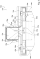
- the cooling body 12a has in particular at least one cooling channel 16a.
- the cooling body 12a could have exactly one cooling channel 16a.
- the cooling channel 16a has, for example, five cooling channels 16a.
- the cooling channels 16a are in particular connected parallel to one another.
- the cooling channels 16a are arranged one above the other in a height direction 54a. In the following, only one of the cooling channels 16a is described by way of example.
- the height direction 54a is particularly aligned perpendicular to a substrate (not shown).
- the height direction 54a is aligned perpendicular to a main extension plane of the household appliance plate 44a.
- the blower unit 18a blows the fluid flow 56a laterally into the cooling channel 16a with respect to the longitudinal direction 20a of the cooling channel 16a.
- the blower unit 18a could blow the fluid flow 56a obliquely into the cooling channel 16a with respect to the longitudinal direction 20a of the cooling channel 16a.
- the blower unit 18a blows the fluid flow 56a at least substantially perpendicularly into the cooling channel 16a with respect to the longitudinal direction 20a of the cooling channel 16a.
- the cooling channel 16a has at least one and advantageously exactly one inlet region 26a, in particular for the inlet of the fluid flow 56a (cf. Figures 2 to 5 and 7 ).
- the inlet region 26a is arranged in at least one side region 24a of the cooling channel 16a.
- the cooling channel 16a has in particular at least one and advantageously at least the side region 24a.
- the fluid flow 56a enters in particular the cooling channel 16a.
- the side region 24a of the cooling channel 16a is arranged in particular on a side of the cooling channel 16a facing the blower unit 18a.
- the blower unit 18a in an operating state in particular blows the fluid flow 56a at least substantially centrally into the cooling channel 16a.
- the inlet region 26a of the cooling channel 16a is arranged at least substantially centrally with respect to the longitudinal extension 22a of the cooling channel 16a in the longitudinal direction 20a of the cooling channel 16a.
- the blower unit 18a effects a, in particular at least substantially uniform, division of the fluid flow 56a into in particular at least two and advantageously exactly two partial fluid flows 58a, in particular by means of the fluid flow 56a blown at least substantially centrally into the cooling channel 16a.
- the outlet regions 28a are arranged on two opposite sides of the cooling channel 16a.
- the outlet regions 28a are arranged in particular with respect to the longitudinal direction 20a at opposite longitudinal end regions of the cooling channel 16a.
- the household appliance device 10a has at least one and, for example, exactly one housing unit 30a (cf. Figures 2 to 7 ).
- the housing unit 30a In an operating state, the housing unit 30a is connected in particular to the household appliance plate 44a, in particular mechanically.
- the housing unit 30a and the household appliance plate 44a are fastened to one another in an operating state.
- the housing unit 30a and the household appliance plate 44a form in particular at least the outer housing of the appliance, in particular at least substantially.
- the housing unit 30a and the household appliance plate 44a delimit and/or define at least one receiving space, in particular designed as a cavity, for receiving and/or storing at least the heat sink 12a, in particular at least substantially.
- the fan unit 18a in an operating state, is arranged at least to a large extent within the housing unit 30a.
- the fan unit 18a in an operating state, is arranged in a rear region 36a of the housing unit 30a when viewed perpendicularly to a main extension plane of at least one housing base 34a of the housing unit 30a.
- the rear region 36a of the housing unit 30a is in particular a region of the housing unit 30a facing away from an operator in an installation position.
- the housing unit 30a delimits the feed channel 32a, in particular from at least three sides.
- the housing unit 30a delimits the feed channel 32a, in particular perpendicular to the height direction 54a, at least partially by means of the housing base 34a.
- the Housing unit 30a forms in particular at least two and advantageously exactly two feed walls 60a. In an operating state, housing unit 30a at least partially delimits feed channel 32a in particular by means of feed walls 60a.
- the household appliance device 10a has in particular at least one and for example exactly one exhaust air unit 38a.
- the exhaust air unit 38a is in particular provided for discharging at least one fluid flow 56a exiting from the cooling channel 16a.
- the exhaust air unit 38a discharges the fluid flow 56a exiting from the cooling channel 16a, in particular at least partially, advantageously at least to a large extent and preferably.
- the exhaust air duct 40a connects, in particular directly, to a longitudinal end region of the cooling duct 16a.
- the exhaust air duct 40a is fluidically connected, in particular directly, to a longitudinal end region of the cooling duct 16a and advantageously to the outlet region 28a of the cooling duct 16a.
- the housing unit 30a forms in particular the exhaust air unit 38a and advantageously the exhaust air duct 40a.
- the housing unit 30a defines the exhaust air unit 38a and advantageously the exhaust air duct 40a, in particular at least partially and advantageously at least to a large extent.
- the housing unit 30a and the exhaust air unit 38a, in particular the exhaust air duct 40a of the exhaust air unit 38a, are in particular formed in one piece.
- the fluid flow 56a is provided for the cooling body 12a, advantageously by the fan unit 18a (cf. Figure 8 ).
- the fluid flow 56a is blown laterally into the cooling channel 16a with respect to the longitudinal direction 20a of the cooling channel 16a, in particular by the blower unit 18a.
- the fluid flow 56a which is blown into the cooling channel 16a by the blower unit 18a in particular, flows, in particular in at least one cooling step 66a, through the cooling channel 16a, in particular in the form of the partial fluid flows 58a and advantageously in two oppositely aligned directions, and at least partially cools the electronic unit 14a in particular by means of the cooling body 12a.
- the exhaust air unit 38a discharges the fluid flow 56a emerging from the cooling channel 16a.
Landscapes
- Engineering & Computer Science (AREA)
- Chemical & Material Sciences (AREA)
- Combustion & Propulsion (AREA)
- Mechanical Engineering (AREA)
- General Engineering & Computer Science (AREA)
- Physics & Mathematics (AREA)
- Electromagnetism (AREA)
- Cooling Or The Like Of Electrical Apparatus (AREA)
Claims (11)
- Dispositif d'appareil ménager, en particulier dispositif d'appareil de cuisson, comprenant au moins un dissipateur de chaleur (12a), lequel présente au moins un canal de refroidissement (16a), au moins une unité de ventilateur (18a) qui fournit dans un état de fonctionnement au moins un courant de fluide (56a) pour le dissipateur de chaleur (12a), et au moins une unité de boîtier (30a), à l'intérieur de laquelle le dissipateur de chaleur (12a) est disposé au moins en grande partie,dans lequel l'unité de ventilateur (18a) insuffle un courant de fluide (56a) dans le canal de refroidissement (16a) latéralement par rapport à une direction longitudinale (20a) du canal de refroidissement (16a),dans lequel l'unité de ventilateur (18a) est disposée à côté du dissipateur de chaleur (12a), dans une vue verticale sur le plan d'extension principale au moins d'un fond de boîtier (34a) de l'unité de boîtier (30a),caractérisé en ce que l'unité de ventilateur (18a) insuffle le courant de fluide (56a) au moins essentiellement perpendiculairement dans le canal de refroidissement (16a) par rapport à la direction longitudinale (20a) du canal de refroidissement (16a).
- Dispositif d'appareil ménager selon la revendication 1, caractérisé en ce que l'unité de ventilateur (18a) insuffle le courant de fluide (56a) au moins essentiellement au milieu du canal de refroidissement (16a), par rapport à une étendue longitudinale (22a) du canal de refroidissement (16a), dans la direction longitudinale (20a) du canal de refroidissement (16a).
- Dispositif d'appareil ménager selon l'une des revendications précédentes, caractérisé en ce que le canal de refroidissement (16a) est configuré sans paroi dans au moins une région latérale (24a), dans laquelle le courant de fluide (56a) pénètre dans le canal de refroidissement (16a), sur une proportion d'au moins 20 % d'une longueur (22a) du canal de refroidissement (16a).
- Dispositif d'appareil ménager selon l'une des revendications précédentes, caractérisé en ce que le canal de refroidissement (16a) présente au moins deux zones de sortie (28a), qui sont prévues pour une sortie d'au moins une partie du courant de fluide (56a).
- Dispositif d'appareil ménager selon la revendication 4, caractérisé en ce que les zones de sortie (28a) sont disposées sur deux côtés opposés l'un à l'autre du canal de refroidissement (16a) par rapport à la direction longitudinale (20a).
- Dispositif d'appareil ménager selon la revendication 1, caractérisé en ce que l'unité de boîtier (30a) présente au moins un canal d'amenée (32a), qui relie l'unité de ventilateur (18a) et le canal de refroidissement (16a) l'un à l'autre de manière fluidique.
- Dispositif d'appareil ménager selon la revendication 1 ou 6, caractérisé en ce que l'unité de ventilateur (18a) est disposée dans une partie arrière (36a) de l'unité de boîtier (30a) dans une vue verticale sur un plan d'extension principale d'au moins le fond de boîtier (34a) de l'unité de boîtier (30a).
- Dispositif d'appareil ménager selon l'une des revendications précédentes, caractérisé par au moins une unité d'extraction d'air (38a), qui présente au moins un conduit d'évacuation d'air (40a) et qui est agencée pour évacuer au moins un courant de fluide (56a) sortant du canal de refroidissement (16a) via le conduit d'évacuation d'air (40a).
- Dispositif d'appareil ménager selon la revendication 8, caractérisé en ce que l'unité de boîtier (30a) définit au moins en partie l'unité d'extraction d'air (38a).
- Appareil ménager, en particulier appareil de cuisson, comprenant au moins un dispositif d'appareil ménager (10a) selon l'une des revendications précédentes.
- Procédé de fonctionnement d'un dispositif d'appareil ménager (10a) selon l'une des revendications 1 à 9, comprenant au moins un dissipateur de chaleur (12a), qui présente au moins un canal de refroidissement (16a), dans lequel au moins un courant de fluide (56a) est fourni pour le dissipateur de chaleur (12a) dans un état de fonctionnement,
dans lequel un courant de fluide (56a) est insufflé latéralement dans le canal de refroidissement (16a) par rapport à une direction longitudinale (20a) du canal de refroidissement (16a).
Applications Claiming Priority (1)
| Application Number | Priority Date | Filing Date | Title |
|---|---|---|---|
| EP19382884 | 2019-10-09 |
Publications (2)
| Publication Number | Publication Date |
|---|---|
| EP3806582A1 EP3806582A1 (fr) | 2021-04-14 |
| EP3806582B1 true EP3806582B1 (fr) | 2024-07-03 |
Family
ID=68503017
Family Applications (1)
| Application Number | Title | Priority Date | Filing Date |
|---|---|---|---|
| EP20199653.5A Active EP3806582B1 (fr) | 2019-10-09 | 2020-10-01 | Dispositif formant appareil électroménager |
Country Status (2)
| Country | Link |
|---|---|
| EP (1) | EP3806582B1 (fr) |
| ES (1) | ES2989195T3 (fr) |
Citations (3)
| Publication number | Priority date | Publication date | Assignee | Title |
|---|---|---|---|---|
| JP2890415B2 (ja) * | 1988-08-16 | 1999-05-17 | 松下電器産業株式会社 | 誘導加熱調理器 |
| EP2292979A1 (fr) * | 2009-09-03 | 2011-03-09 | BSH Bosch und Siemens Hausgeräte GmbH | Dispositif de refroidissement pour un appareil ménager et appareil ménager, notamment champ de cuisson à induction, doté d'un dispositif de refroidissement |
| EP2679913A2 (fr) * | 2012-06-28 | 2014-01-01 | BSH Bosch und Siemens Hausgeräte GmbH | Dispositif d'appareil ménager |
Family Cites Families (3)
| Publication number | Priority date | Publication date | Assignee | Title |
|---|---|---|---|---|
| JP4016808B2 (ja) * | 2002-11-07 | 2007-12-05 | 松下電器産業株式会社 | 調理器 |
| JP2008287938A (ja) * | 2007-05-15 | 2008-11-27 | Chugoku Electric Power Co Inc:The | 電磁調理器 |
| JP2009094088A (ja) * | 2009-02-02 | 2009-04-30 | Hitachi Appliances Inc | 誘導加熱調理器 |
-
2020
- 2020-10-01 ES ES20199653T patent/ES2989195T3/es active Active
- 2020-10-01 EP EP20199653.5A patent/EP3806582B1/fr active Active
Patent Citations (3)
| Publication number | Priority date | Publication date | Assignee | Title |
|---|---|---|---|---|
| JP2890415B2 (ja) * | 1988-08-16 | 1999-05-17 | 松下電器産業株式会社 | 誘導加熱調理器 |
| EP2292979A1 (fr) * | 2009-09-03 | 2011-03-09 | BSH Bosch und Siemens Hausgeräte GmbH | Dispositif de refroidissement pour un appareil ménager et appareil ménager, notamment champ de cuisson à induction, doté d'un dispositif de refroidissement |
| EP2679913A2 (fr) * | 2012-06-28 | 2014-01-01 | BSH Bosch und Siemens Hausgeräte GmbH | Dispositif d'appareil ménager |
Also Published As
| Publication number | Publication date |
|---|---|
| ES2989195T3 (es) | 2024-11-25 |
| EP3806582A1 (fr) | 2021-04-14 |
Similar Documents
| Publication | Publication Date | Title |
|---|---|---|
| EP2909901B1 (fr) | Boîtier antidéflagrant équipé d'un ventilateur | |
| EP1340945B1 (fr) | Appareil pour traitement et préparation d'aliments avec réchauffage à gaz | |
| EP3338028B1 (fr) | Appareil combiné avec plaque de cuisson et dispositif d'evacuation des fumées | |
| DE202005004274U1 (de) | Elektromotorisch angetriebenes Radialgebläse mit IC | |
| WO2020169421A2 (fr) | Ensemble pour le refroidissement uniforme de pièces et véhicule à moteur pourvu d'au moins un ensemble | |
| EP3628932B1 (fr) | Plaque de cuisson | |
| EP1970635B1 (fr) | Four à air chaud doté de déflecteurs | |
| EP2679913A2 (fr) | Dispositif d'appareil ménager | |
| DE19935835C5 (de) | Induktionskochfeld mit Kühlgebläse | |
| DE102007029178A1 (de) | Kältegerät mit Lüfteraggregat | |
| DE10048877A1 (de) | Klimagerät | |
| EP3806582B1 (fr) | Dispositif formant appareil électroménager | |
| EP3453974A1 (fr) | Dispositif formant plaque de cuisson | |
| DE20104205U1 (de) | Heißlufttrockner für eine Beschichtungsanlage | |
| EP0942235A1 (fr) | Feu de boulanger avec boíte d'aspiration | |
| DE9200134U1 (de) | Kühlgerät für Schaltschränke | |
| EP3623705A1 (fr) | Appareil de cuisson | |
| EP1431670A2 (fr) | Boíte pour un appareil de cuisson | |
| DE2933696C2 (fr) | ||
| EP0003764A1 (fr) | Four de cuisson double, en particulier four de cuisson encastré | |
| EP3572673A1 (fr) | Système de cuisson | |
| DE102009026645B4 (de) | Gargerät | |
| DE112019007369B4 (de) | Inneneinheit einer Klimaanlage | |
| WO2008148675A2 (fr) | Four | |
| DE102022208905A1 (de) | Kältegerät und Wärmetauscherbaugruppe für ein Kältegerät |
Legal Events
| Date | Code | Title | Description |
|---|---|---|---|
| PUAI | Public reference made under article 153(3) epc to a published international application that has entered the european phase |
Free format text: ORIGINAL CODE: 0009012 |
|
| STAA | Information on the status of an ep patent application or granted ep patent |
Free format text: STATUS: THE APPLICATION HAS BEEN PUBLISHED |
|
| AK | Designated contracting states |
Kind code of ref document: A1 Designated state(s): AL AT BE BG CH CY CZ DE DK EE ES FI FR GB GR HR HU IE IS IT LI LT LU LV MC MK MT NL NO PL PT RO RS SE SI SK SM TR |
|
| AX | Request for extension of the european patent |
Extension state: BA ME |
|
| STAA | Information on the status of an ep patent application or granted ep patent |
Free format text: STATUS: REQUEST FOR EXAMINATION WAS MADE |
|
| 17P | Request for examination filed |
Effective date: 20211014 |
|
| RBV | Designated contracting states (corrected) |
Designated state(s): AL AT BE BG CH CY CZ DE DK EE ES FI FR GB GR HR HU IE IS IT LI LT LU LV MC MK MT NL NO PL PT RO RS SE SI SK SM TR |
|
| STAA | Information on the status of an ep patent application or granted ep patent |
Free format text: STATUS: EXAMINATION IS IN PROGRESS |
|
| 17Q | First examination report despatched |
Effective date: 20220708 |
|
| GRAP | Despatch of communication of intention to grant a patent |
Free format text: ORIGINAL CODE: EPIDOSNIGR1 |
|
| STAA | Information on the status of an ep patent application or granted ep patent |
Free format text: STATUS: GRANT OF PATENT IS INTENDED |
|
| RIC1 | Information provided on ipc code assigned before grant |
Ipc: F24C 15/00 20060101ALI20240130BHEP Ipc: F24C 15/10 20060101ALI20240130BHEP Ipc: H05B 6/12 20060101AFI20240130BHEP |
|
| INTG | Intention to grant announced |
Effective date: 20240226 |
|
| GRAS | Grant fee paid |
Free format text: ORIGINAL CODE: EPIDOSNIGR3 |
|
| GRAA | (expected) grant |
Free format text: ORIGINAL CODE: 0009210 |
|
| STAA | Information on the status of an ep patent application or granted ep patent |
Free format text: STATUS: THE PATENT HAS BEEN GRANTED |
|
| AK | Designated contracting states |
Kind code of ref document: B1 Designated state(s): AL AT BE BG CH CY CZ DE DK EE ES FI FR GB GR HR HU IE IS IT LI LT LU LV MC MK MT NL NO PL PT RO RS SE SI SK SM TR |
|
| REG | Reference to a national code |
Ref country code: CH Ref legal event code: EP |
|
| REG | Reference to a national code |
Ref country code: DE Ref legal event code: R096 Ref document number: 502020008437 Country of ref document: DE |
|
| REG | Reference to a national code |
Ref country code: LT Ref legal event code: MG9D |
|
| REG | Reference to a national code |
Ref country code: NL Ref legal event code: MP Effective date: 20240703 |
|
| REG | Reference to a national code |
Ref country code: ES Ref legal event code: FG2A Ref document number: 2989195 Country of ref document: ES Kind code of ref document: T3 Effective date: 20241125 |
|
| PG25 | Lapsed in a contracting state [announced via postgrant information from national office to epo] |
Ref country code: PT Free format text: LAPSE BECAUSE OF FAILURE TO SUBMIT A TRANSLATION OF THE DESCRIPTION OR TO PAY THE FEE WITHIN THE PRESCRIBED TIME-LIMIT Effective date: 20241104 |
|
| PG25 | Lapsed in a contracting state [announced via postgrant information from national office to epo] |
Ref country code: NL Free format text: LAPSE BECAUSE OF FAILURE TO SUBMIT A TRANSLATION OF THE DESCRIPTION OR TO PAY THE FEE WITHIN THE PRESCRIBED TIME-LIMIT Effective date: 20240703 |
|
| PG25 | Lapsed in a contracting state [announced via postgrant information from national office to epo] |
Ref country code: PT Free format text: LAPSE BECAUSE OF FAILURE TO SUBMIT A TRANSLATION OF THE DESCRIPTION OR TO PAY THE FEE WITHIN THE PRESCRIBED TIME-LIMIT Effective date: 20241104 Ref country code: NL Free format text: LAPSE BECAUSE OF FAILURE TO SUBMIT A TRANSLATION OF THE DESCRIPTION OR TO PAY THE FEE WITHIN THE PRESCRIBED TIME-LIMIT Effective date: 20240703 |
|
| PG25 | Lapsed in a contracting state [announced via postgrant information from national office to epo] |
Ref country code: NO Free format text: LAPSE BECAUSE OF FAILURE TO SUBMIT A TRANSLATION OF THE DESCRIPTION OR TO PAY THE FEE WITHIN THE PRESCRIBED TIME-LIMIT Effective date: 20241003 |
|
| PG25 | Lapsed in a contracting state [announced via postgrant information from national office to epo] |
Ref country code: FI Free format text: LAPSE BECAUSE OF FAILURE TO SUBMIT A TRANSLATION OF THE DESCRIPTION OR TO PAY THE FEE WITHIN THE PRESCRIBED TIME-LIMIT Effective date: 20240703 Ref country code: GR Free format text: LAPSE BECAUSE OF FAILURE TO SUBMIT A TRANSLATION OF THE DESCRIPTION OR TO PAY THE FEE WITHIN THE PRESCRIBED TIME-LIMIT Effective date: 20241004 Ref country code: PL Free format text: LAPSE BECAUSE OF FAILURE TO SUBMIT A TRANSLATION OF THE DESCRIPTION OR TO PAY THE FEE WITHIN THE PRESCRIBED TIME-LIMIT Effective date: 20240703 |
|
| PG25 | Lapsed in a contracting state [announced via postgrant information from national office to epo] |
Ref country code: BG Free format text: LAPSE BECAUSE OF FAILURE TO SUBMIT A TRANSLATION OF THE DESCRIPTION OR TO PAY THE FEE WITHIN THE PRESCRIBED TIME-LIMIT Effective date: 20240703 |
|
| PG25 | Lapsed in a contracting state [announced via postgrant information from national office to epo] |
Ref country code: LV Free format text: LAPSE BECAUSE OF FAILURE TO SUBMIT A TRANSLATION OF THE DESCRIPTION OR TO PAY THE FEE WITHIN THE PRESCRIBED TIME-LIMIT Effective date: 20240703 |
|
| PG25 | Lapsed in a contracting state [announced via postgrant information from national office to epo] |
Ref country code: IS Free format text: LAPSE BECAUSE OF FAILURE TO SUBMIT A TRANSLATION OF THE DESCRIPTION OR TO PAY THE FEE WITHIN THE PRESCRIBED TIME-LIMIT Effective date: 20241103 |
|
| PG25 | Lapsed in a contracting state [announced via postgrant information from national office to epo] |
Ref country code: CZ Free format text: LAPSE BECAUSE OF FAILURE TO SUBMIT A TRANSLATION OF THE DESCRIPTION OR TO PAY THE FEE WITHIN THE PRESCRIBED TIME-LIMIT Effective date: 20240703 Ref country code: HR Free format text: LAPSE BECAUSE OF FAILURE TO SUBMIT A TRANSLATION OF THE DESCRIPTION OR TO PAY THE FEE WITHIN THE PRESCRIBED TIME-LIMIT Effective date: 20240703 |
|
| PG25 | Lapsed in a contracting state [announced via postgrant information from national office to epo] |
Ref country code: RS Free format text: LAPSE BECAUSE OF FAILURE TO SUBMIT A TRANSLATION OF THE DESCRIPTION OR TO PAY THE FEE WITHIN THE PRESCRIBED TIME-LIMIT Effective date: 20241003 |
|
| PG25 | Lapsed in a contracting state [announced via postgrant information from national office to epo] |
Ref country code: RS Free format text: LAPSE BECAUSE OF FAILURE TO SUBMIT A TRANSLATION OF THE DESCRIPTION OR TO PAY THE FEE WITHIN THE PRESCRIBED TIME-LIMIT Effective date: 20241003 Ref country code: PL Free format text: LAPSE BECAUSE OF FAILURE TO SUBMIT A TRANSLATION OF THE DESCRIPTION OR TO PAY THE FEE WITHIN THE PRESCRIBED TIME-LIMIT Effective date: 20240703 Ref country code: NO Free format text: LAPSE BECAUSE OF FAILURE TO SUBMIT A TRANSLATION OF THE DESCRIPTION OR TO PAY THE FEE WITHIN THE PRESCRIBED TIME-LIMIT Effective date: 20241003 Ref country code: LV Free format text: LAPSE BECAUSE OF FAILURE TO SUBMIT A TRANSLATION OF THE DESCRIPTION OR TO PAY THE FEE WITHIN THE PRESCRIBED TIME-LIMIT Effective date: 20240703 Ref country code: IS Free format text: LAPSE BECAUSE OF FAILURE TO SUBMIT A TRANSLATION OF THE DESCRIPTION OR TO PAY THE FEE WITHIN THE PRESCRIBED TIME-LIMIT Effective date: 20241103 Ref country code: HR Free format text: LAPSE BECAUSE OF FAILURE TO SUBMIT A TRANSLATION OF THE DESCRIPTION OR TO PAY THE FEE WITHIN THE PRESCRIBED TIME-LIMIT Effective date: 20240703 Ref country code: GR Free format text: LAPSE BECAUSE OF FAILURE TO SUBMIT A TRANSLATION OF THE DESCRIPTION OR TO PAY THE FEE WITHIN THE PRESCRIBED TIME-LIMIT Effective date: 20241004 Ref country code: FI Free format text: LAPSE BECAUSE OF FAILURE TO SUBMIT A TRANSLATION OF THE DESCRIPTION OR TO PAY THE FEE WITHIN THE PRESCRIBED TIME-LIMIT Effective date: 20240703 Ref country code: CZ Free format text: LAPSE BECAUSE OF FAILURE TO SUBMIT A TRANSLATION OF THE DESCRIPTION OR TO PAY THE FEE WITHIN THE PRESCRIBED TIME-LIMIT Effective date: 20240703 Ref country code: BG Free format text: LAPSE BECAUSE OF FAILURE TO SUBMIT A TRANSLATION OF THE DESCRIPTION OR TO PAY THE FEE WITHIN THE PRESCRIBED TIME-LIMIT Effective date: 20240703 |
|
| REG | Reference to a national code |
Ref country code: DE Ref legal event code: R097 Ref document number: 502020008437 Country of ref document: DE |
|
| PG25 | Lapsed in a contracting state [announced via postgrant information from national office to epo] |
Ref country code: DK Free format text: LAPSE BECAUSE OF FAILURE TO SUBMIT A TRANSLATION OF THE DESCRIPTION OR TO PAY THE FEE WITHIN THE PRESCRIBED TIME-LIMIT Effective date: 20240703 Ref country code: RO Free format text: LAPSE BECAUSE OF FAILURE TO SUBMIT A TRANSLATION OF THE DESCRIPTION OR TO PAY THE FEE WITHIN THE PRESCRIBED TIME-LIMIT Effective date: 20240703 Ref country code: SM Free format text: LAPSE BECAUSE OF FAILURE TO SUBMIT A TRANSLATION OF THE DESCRIPTION OR TO PAY THE FEE WITHIN THE PRESCRIBED TIME-LIMIT Effective date: 20240703 |
|
| PG25 | Lapsed in a contracting state [announced via postgrant information from national office to epo] |
Ref country code: EE Free format text: LAPSE BECAUSE OF FAILURE TO SUBMIT A TRANSLATION OF THE DESCRIPTION OR TO PAY THE FEE WITHIN THE PRESCRIBED TIME-LIMIT Effective date: 20240703 |
|
| PG25 | Lapsed in a contracting state [announced via postgrant information from national office to epo] |
Ref country code: SK Free format text: LAPSE BECAUSE OF FAILURE TO SUBMIT A TRANSLATION OF THE DESCRIPTION OR TO PAY THE FEE WITHIN THE PRESCRIBED TIME-LIMIT Effective date: 20240703 |
|
| PLBE | No opposition filed within time limit |
Free format text: ORIGINAL CODE: 0009261 |
|
| STAA | Information on the status of an ep patent application or granted ep patent |
Free format text: STATUS: NO OPPOSITION FILED WITHIN TIME LIMIT |
|
| REG | Reference to a national code |
Ref country code: CH Ref legal event code: PL |
|
| 26N | No opposition filed |
Effective date: 20250404 |
|
| PG25 | Lapsed in a contracting state [announced via postgrant information from national office to epo] |
Ref country code: MC Free format text: LAPSE BECAUSE OF FAILURE TO SUBMIT A TRANSLATION OF THE DESCRIPTION OR TO PAY THE FEE WITHIN THE PRESCRIBED TIME-LIMIT Effective date: 20240703 |
|
| PG25 | Lapsed in a contracting state [announced via postgrant information from national office to epo] |
Ref country code: LU Free format text: LAPSE BECAUSE OF NON-PAYMENT OF DUE FEES Effective date: 20241001 Ref country code: BE Free format text: LAPSE BECAUSE OF NON-PAYMENT OF DUE FEES Effective date: 20241031 |
|
| PG25 | Lapsed in a contracting state [announced via postgrant information from national office to epo] |
Ref country code: CH Free format text: LAPSE BECAUSE OF NON-PAYMENT OF DUE FEES Effective date: 20241031 |
|
| REG | Reference to a national code |
Ref country code: BE Ref legal event code: MM Effective date: 20241031 |
|
| PG25 | Lapsed in a contracting state [announced via postgrant information from national office to epo] |
Ref country code: SE Free format text: LAPSE BECAUSE OF FAILURE TO SUBMIT A TRANSLATION OF THE DESCRIPTION OR TO PAY THE FEE WITHIN THE PRESCRIBED TIME-LIMIT Effective date: 20240703 |
|
| PG25 | Lapsed in a contracting state [announced via postgrant information from national office to epo] |
Ref country code: IE Free format text: LAPSE BECAUSE OF NON-PAYMENT OF DUE FEES Effective date: 20241001 |
|
| PGFP | Annual fee paid to national office [announced via postgrant information from national office to epo] |
Ref country code: DE Payment date: 20251031 Year of fee payment: 6 |
|
| PGFP | Annual fee paid to national office [announced via postgrant information from national office to epo] |
Ref country code: GB Payment date: 20251024 Year of fee payment: 6 |
|
| PGFP | Annual fee paid to national office [announced via postgrant information from national office to epo] |
Ref country code: AT Payment date: 20260113 Year of fee payment: 5 |
|
| PGFP | Annual fee paid to national office [announced via postgrant information from national office to epo] |
Ref country code: IT Payment date: 20251031 Year of fee payment: 6 |
|
| PGFP | Annual fee paid to national office [announced via postgrant information from national office to epo] |
Ref country code: FR Payment date: 20251024 Year of fee payment: 6 |
|
| PG25 | Lapsed in a contracting state [announced via postgrant information from national office to epo] |
Ref country code: CY Free format text: LAPSE BECAUSE OF FAILURE TO SUBMIT A TRANSLATION OF THE DESCRIPTION OR TO PAY THE FEE WITHIN THE PRESCRIBED TIME-LIMIT; INVALID AB INITIO Effective date: 20201001 |
|
| PGFP | Annual fee paid to national office [announced via postgrant information from national office to epo] |
Ref country code: ES Payment date: 20251114 Year of fee payment: 6 |
|
| PG25 | Lapsed in a contracting state [announced via postgrant information from national office to epo] |
Ref country code: HU Free format text: LAPSE BECAUSE OF FAILURE TO SUBMIT A TRANSLATION OF THE DESCRIPTION OR TO PAY THE FEE WITHIN THE PRESCRIBED TIME-LIMIT; INVALID AB INITIO Effective date: 20201001 |