EP3806702B1 - Cooking apparatus of the hot air deep fat fryer type with a system for closing the hot air extractor - Google Patents
Cooking apparatus of the hot air deep fat fryer type with a system for closing the hot air extractor Download PDFInfo
- Publication number
- EP3806702B1 EP3806702B1 EP19730346.4A EP19730346A EP3806702B1 EP 3806702 B1 EP3806702 B1 EP 3806702B1 EP 19730346 A EP19730346 A EP 19730346A EP 3806702 B1 EP3806702 B1 EP 3806702B1
- Authority
- EP
- European Patent Office
- Prior art keywords
- cooking
- hot air
- cooking apparatus
- air
- cooking chamber
- Prior art date
- Legal status (The legal status is an assumption and is not a legal conclusion. Google has not performed a legal analysis and makes no representation as to the accuracy of the status listed.)
- Active
Links
Images

Classifications
-
- A—HUMAN NECESSITIES
- A47—FURNITURE; DOMESTIC ARTICLES OR APPLIANCES; COFFEE MILLS; SPICE MILLS; SUCTION CLEANERS IN GENERAL
- A47J—KITCHEN EQUIPMENT; COFFEE MILLS; SPICE MILLS; APPARATUS FOR MAKING BEVERAGES
- A47J37/00—Baking; Roasting; Grilling; Frying
- A47J37/06—Roasters; Grills; Sandwich grills
- A47J37/0623—Small-size cooking ovens, i.e. defining an at least partially closed cooking cavity
- A47J37/0629—Small-size cooking ovens, i.e. defining an at least partially closed cooking cavity with electric heating elements
- A47J37/0641—Small-size cooking ovens, i.e. defining an at least partially closed cooking cavity with electric heating elements with forced air circulation, e.g. air fryers
Definitions
- the present invention relates to cooking appliances, more precisely to hot air fryers allowing food to be cooked using very little oil, or even no oil at all.
- the invention relates in particular to such hot air fryers which comprise an air circulation device comprising fresh air suction means and hot air extraction means, said extraction means being equipped with a system for closing the hot air extraction in order to modify the cooking of the food.
- Hot air fryer-type cooking appliances are known to those skilled in the art. Such cooking appliances make it possible to significantly reduce the amount of fat, or even eliminate it completely, during the cooking of foods that may be of plant or animal origin, for example fries, vegetables, meat or fish. Indeed, cooking is carried out with little or no oil thanks to hot air circulating in a cooking chamber, which allows for the consumption of more dietetic foods.
- Such a cooking appliance generally comprises a tank which receives a basket in which food to be cooked is arranged. Once the food is arranged in the basket and the basket is positioned in the tank, the cooking appliance can be closed to form a cooking chamber incorporating the tank, the basket and the food. Hot air is then forced into this cooking chamber by means of a heating device and an air circulation device, the circulation of the hot air thus ensuring the cooking of the food.
- the air circulation device comprises fresh air suction means configured to supply fresh air to the cooking chamber and air extraction means hot air configured to exhaust hot air from the cooking chamber.
- Cooking appliances are known for which said extraction means comprise a closure system configured to be activated either in the open position allowing the evacuation of hot air or in the closed position limiting the evacuation of hot air, in order to create a confined atmosphere in the cooking chamber.
- Utility models will be cited in particular CN204708660U , CN204813499U and patent applications CN106618249A And WO2017072068A1 .
- In the closed position of the shutter system cooking in such a confined atmosphere, loaded with water vapor, allows the food to be cooked while preventing it from drying out in order to preserve all its softness.
- cooking in a drier atmosphere allows the food to be browned in order to make it crispy.
- US2014318388A1 discloses automatic positioning of a shutter based on the selected cooking mode and not during a cooking cycle based on a cooking parameter which includes the humidity level, the temperature, the cooking time or the pressure exerted in the cooking chamber.
- the document CN206303774U discloses a motorized shutter to manage the temperature, humidity or pressure inside the cooking chamber during a single cooking cycle.
- the present invention relates to a cooking appliance having such extraction means equipped with a sealing system, the objective being to ensure perfect control of the cooking of food at a lower cost.
- the at least one determined cooking parameter comprises the humidity level, the temperature, the cooking time or even the pressure exerted in the cooking chamber.
- the cooking appliance according to the invention makes it possible to precisely manage the cooking of food in a confined or non-confined atmosphere.
- the cooking appliance makes it possible to start cooking food in a confined atmosphere, by placing the closure system in the closed position, so that said food retains its softness. Then, when the control device detects that the at least one cooking parameter has reached a defined value, the closure system can move to the open position, the cooking of the food continuing with a drier atmosphere, in order to brown and crisp the food on the surface, the center of this food remaining soft.
- the control device comprises at least one member for measuring the at least one cooking parameter and a control unit configured to process data returned by the measuring member and to activate the sealing system as a function of said data.
- the term “measuring member” means a member allowing the measurement of a physical parameter, but also a member allowing the counting of a time parameter.
- the at least one measuring member is chosen from a humidity sensor placed in the cooking chamber, a cooking time counting unit, a temperature sensor placed in the cooking chamber. cooking and a pressure sensor placed in the cooking chamber.
- the control device comprises a selection member configured to specify the type of food to be cooked from among several possible choices and/or the desired type of cooking.
- the control unit is configured to activate the shutter system based on the data returned by the measuring member and the selection made.
- the control unit adjusts the reference value of the at least one cooking parameter, which ultimately makes it possible to best adapt the cooking time with the shutter system in the closed position and that with the shutter system in the open position.
- the extraction means comprise an extraction mouth and a mechanism for closing the extraction mouth, said closing mechanism being configured to be actuated in said open and closed positions.
- the closing mechanism is configured to be manually actuated.
- the control device comprises at least one audible or visual indicator specifying to a user to actuate the closing mechanism at least in the open position, during cooking. It is also possible to envisage that the audible or visual indicator specifies to the user to actuate the closing mechanism in the closed position.
- the closing mechanism comprises a manual activation lever.
- the closing mechanism comprises a grid provided with passages, the grid being arranged at the extraction mouth.
- the closing mechanism comprises a hatch movable relative to the grid, the hatch being arranged to be moved into a position for closing the passages or into a position for clearing the passages.
- the closing mechanism comprises a grid with movable flaps.
- the flaps are arranged to be moved into a gate open position or a gate closed position.
- the closing mechanism comprises at least one passage and at least one flap. Furthermore, each flap is arranged to be pressed against the respective passage in order to close it or to be disengaged from said passage in order to open it.
- the cooking appliance consists of an example of a hot air fryer, other designs of hot air fryers existing and also being able to include the essential characteristics which are the subject of the present invention which will be detailed below.
- fryer will be used to designate the cooking appliance 1, unless otherwise indicated.
- the fryer 1 comprises a shell 2 having a wall 3 arranged on the rear face 1a of the fryer 1, while the front face 1b of this fryer 1 allows the insertion of a tank 4 in the manner of a drawer in a cooking chamber 5 arranged inside the shell 2, said tank 4 being manipulated by means of a handling handle 6.
- a heating device 7 is arranged inside the shell 2, above the cooking chamber 5.
- an air circulation device 8 allows fresh air to be sucked in through a lower part 9a of a grid 9 which is arranged on the wall 3, this fresh air enters through a suction mouth 10 then is conveyed to the heating device 7 in order to be heated and, finally, to the cooking chamber 5.
- the hot air is then discharged outside the fryer 1, through an extraction mouth 11 which opens into the upper part 9b of the grid 9.
- the air circulation device 8 comprises a fan 12 making it possible to convey the air from the suction mouth 10 to the extraction mouth 11.
- the various electrical components of the fryer 1, including in particular the heating device 7 and the fan 12, are connected to an electrical supply circuit (not illustrated) which comprises in particular a control unit 13 (shown diagrammatically in figure 8 ) of the electronic card type.
- a control unit 13 shown diagrammatically in figure 8
- Such characteristics are known on the fryers currently on the market, which is why they will not be detailed; those skilled in the art may, for example, refer to the hot air fryers developed by the applicant, for example the one marketed under the name FRY DELIGHT ® .
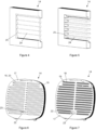
- a closing mechanism 14 is arranged at the extraction mouth 11, behind the grid 9 arranged on the wall 3.
- the closing mechanism 14 deliberately does not appear on the Figure 1 , in order to better distinguish the grid 9 and the extraction mouth 11.
- This closing mechanism 14 can be activated either in an open position, illustrated in Figure 2 , either in a closed position shown in Figure 3
- the open position allows the extraction of hot air, as shown by arrows 15, while the closed position blocks the extraction of hot air, as shown by arrows 16.
- the closing mechanism 14 comprises a grid 17 provided with passages 18 and a trapdoor 19 arranged behind this grid 17 and also provided with passages 20.
- the trapdoor 19 is movable in translation to make the passages coincide 20 of said hatch 19 with the passages 18 of the grid 17, thus corresponding to said open position, or to close the passages 18 of the grid by means of said hatch 19, thus corresponding to said closed position.
- the activation of the hatch 19 is carried out by means of an actuator 21 (shown diagrammatically on the figure 8 ) which may be electric, electromagnetic, electromechanical or other, for example a mini electric cylinder, a motor or an electromagnet with a mechanical system of the cam/link or spring type.
- This actuator 21 is controlled by the control unit 13, shown diagrammatically in figure 8 .
- FIGS. 6 and 7 illustrate a variant of the closing mechanism 14 comprising, as previously, a grid 17 provided with passages 18 and a trapdoor 19 provided with passages 20.
- the trapdoor 19 is movable in translation to make the passages 20 of said trapdoor 19 coincide with the passages 18 of the grid 17 ( Figure 6 ) or to close the passages 18 of the grid by means of said trapdoor 19 ( Figure 7 ).
- the activation of the hatch 19 is carried out by means of a lever 22 secured to the hatch 19 and capable of sliding in a slot 23 on the grid 17 to reach the open and closed positions of the closing mechanism 14.
- the closing mechanism 14 will be arranged in place of the grid 9, at the limit of the extraction mouth 11, in order to be able to access the lever 22 via the rear face 1a of the fryer 1 and manipulate it with one hand.
- the closing mechanism 14 is shutters 24 which can pivot from a window closing position 25, as illustrated in Figure 4 , blocking the passage of hot air, towards an open position of the window 25, as illustrated in Figure 5 , allowing the extraction of hot air.
- the activation of the shutters 24 can be carried out by an actuator 21 controlled by the control unit 13, this actuator 21 being for example a mini-electric motor (not shown) which, by means of a transmission system (not shown), causes the pivoting of all the shutters 24 from the closed position to the open position, and vice versa.
- the closing mechanism 14 with shutters 24 can be arranged in a position similar to the Figure 2 .
- the activation of the shutters 24 can be carried out manually, by means of a lever (not illustrated) causing the pivoting of these shutters 24 from the open position to the closed position, and vice versa.
- the closing mechanism 14 will be arranged in place of the grid 9, at the limit of the extraction mouth 11, in order to be able to access the lever via the rear face 1a of the fryer 1 and handle it.
- a closing mechanism 14 equipped with a flap (not shown) sliding towards an open position and towards a closed position of a passage on the extraction mouth 11, the activation of the flap being done manually by means of a lever.
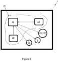
- the fryer 1 also includes a control device 26, shown diagrammatically in figure 8 , which makes it possible to control the opening of the closing mechanism 14, according to the various variants described above without limitation. Controlling the extraction of hot air, loaded with water vapor, makes it possible to adjust the cooking of the food so that it is more or less soft and/or more or less crispy.
- the control device 26 is implemented by means of the control unit 13 which will allow the activation of the closing mechanism 14 to be triggered when one or more cooking parameters are established.
- the control unit 13 activates an indicator 27 which may be a buzzer or a beep, or even a light, said indicator 27 making it possible to signal to the user to activate the lever to move the closing mechanism 14 to the open position.
- the fryer 1 comprises one or more measuring members 28 which may be a pressure sensor, a humidity sensor or a temperature sensor, which are placed in the cooking chamber 5 to measure respectively the pressure, the humidity level or the temperature in the cooking chamber 5.
- This measuring member 28 may also be a counting unit incorporated in the control unit 13 and allowing the cooking time to be measured.
- the control unit 13 processes the data transmitted by the measuring member(s) 28 and acts accordingly on the actuator 21 or on the indicator 27, as the case may be, when threshold values of pressure, temperature, humidity level and/or time are reached for these various parameters.
- the fryer 1 comprises a selection member 29 which can be composed of one or more selection buttons or a keypad or touchscreen, connected to the control unit 13.
- the control unit 13 will process the data from the selection retained to adjust the thresholds of the pressure, humidity, temperature and/or time parameters, according to those taken into account by the fryer 1.
- control unit 13 could also act on the actuator 21 or on the indicator 27 for activating the closing mechanism 14 in the closed position.
- the control unit 13 could also provide one or more sequences for activating the closing and opening of the closing mechanism 14 during a cooking cycle, depending on the type of food to be cooked and/or the desired cooking.
Landscapes
- Engineering & Computer Science (AREA)
- Food Science & Technology (AREA)
- Frying-Pans Or Fryers (AREA)
Description
La présente invention concerne les appareils de cuisson, plus précisément les friteuses à air chaud permettant de réaliser une cuisson des aliments en utilisant très peu d'huile, voire pas du tout d'huile.The present invention relates to cooking appliances, more precisely to hot air fryers allowing food to be cooked using very little oil, or even no oil at all.
L'invention porte tout particulièrement sur de telles friteuses à air chaud qui comprennent un dispositif de circulation d'air comprenant des moyens d'aspiration d'air frais et des moyens d'extraction d'air chaud, lesdits moyens d'extraction étant équipés d'un système d'obturation de l'extraction de l'air chaud afin de modifier la cuisson des aliments.The invention relates in particular to such hot air fryers which comprise an air circulation device comprising fresh air suction means and hot air extraction means, said extraction means being equipped with a system for closing the hot air extraction in order to modify the cooking of the food.
Les appareils de cuisson de type friteuse à air chaud sont connus de l'homme du métier. De tels appareils de cuisson permettent de réduire fortement la quantité de matière grasse, voire de la supprimer complètement, pendant la cuisson des aliments qui peuvent être d'origine végétale ou animale, par exemple des frites, des légumes, de la viande ou du poisson. En effet, la cuisson s'effectue avec peu ou pas d'huile grâce à de l'air chaud circulant dans une chambre de cuisson, ce qui permet de consommer des aliments plus diététiques.Hot air fryer-type cooking appliances are known to those skilled in the art. Such cooking appliances make it possible to significantly reduce the amount of fat, or even eliminate it completely, during the cooking of foods that may be of plant or animal origin, for example fries, vegetables, meat or fish. Indeed, cooking is carried out with little or no oil thanks to hot air circulating in a cooking chamber, which allows for the consumption of more dietetic foods.
Un tel appareil de cuisson comprend généralement une cuve qui reçoit un panier dans lequel sont disposés des aliments à cuire. Une fois les aliments disposés dans le panier et celui-ci positionné dans la cuve, l'appareil de cuisson peut être fermé pour former une chambre de cuisson incorporant la cuve, le panier et les aliments. De l'air chaud est ensuite pulsé dans cette chambre de cuisson au moyen d'un dispositif de chauffe et d'un dispositif de circulation d'air, la circulation de l'air chaud assurant ainsi la cuisson des aliments.Such a cooking appliance generally comprises a tank which receives a basket in which food to be cooked is arranged. Once the food is arranged in the basket and the basket is positioned in the tank, the cooking appliance can be closed to form a cooking chamber incorporating the tank, the basket and the food. Hot air is then forced into this cooking chamber by means of a heating device and an air circulation device, the circulation of the hot air thus ensuring the cooking of the food.
Le dispositif de circulation d'air comprend des moyens d'aspiration d'air frais configurés pour alimenter en air frais la chambre de cuisson et des moyens d'extraction d'air chaud configurés pour évacuer l'air chaud de la chambre de cuisson.The air circulation device comprises fresh air suction means configured to supply fresh air to the cooking chamber and air extraction means hot air configured to exhaust hot air from the cooking chamber.
Il est connu des appareils de cuisson pour lesquels lesdits moyens d'extraction comprennent un système d'obturation configuré pour être activé soit en position ouverte autorisant l'évacuation de l'air chaud soit en position fermée limitant l'évacuation de l'air chaud, afin de créer une atmosphère confinée dans la chambre de cuisson. On citera notamment les modèles d'utilité
Le document
Le document
La présente invention concerne un appareil de cuisson présentant de tels moyens d'extraction muni d'un système d'obturation, l'objectif étant d'assurer une parfaite maîtrise de la cuisson des aliments à moindre coût.The present invention relates to a cooking appliance having such extraction means equipped with a sealing system, the objective being to ensure perfect control of the cooking of food at a lower cost.
A cette effet, l'invention concerne un appareil de cuisson de type friteuse à air chaud, comprenant une chambre de cuisson et un dispositif de circulation d'air comprenant :
- des moyens d'aspiration d'air frais configurés pour acheminer l'air frais vers un dispositif de chauffe de cet air, l'air ainsi chauffé alimentant ensuite la chambre de cuisson et,
- des moyens d'extraction d'air chaud configurés pour évacuer l'air chaud de la chambre de cuisson, les moyens d'extraction comprenant un système d'obturation configuré pour être activé soit en position ouverte autorisant l'évacuation de l'air chaud soit en position fermée limitant l'évacuation de l'air chaud de manière à créer une atmosphère confinée dans la chambre de cuisson,
- fresh air suction means configured to convey the fresh air to a device for heating this air, the air thus heated then supplying the cooking chamber and,
- hot air extraction means configured to evacuate hot air from the cooking chamber, the extraction means comprising a shutter system configured to be activated either in the open position allowing the evacuation of hot air either in the closed position limiting the evacuation of hot air so as to create a confined atmosphere in the cooking chamber,
Ainsi, selon l'invention, l'au moins un paramètre de cuisson déterminé comprend le taux d'humidité, la température, le temps de cuisson ou encore la pression s'exerçant dans la chambre de cuisson.Thus, according to the invention, the at least one determined cooking parameter comprises the humidity level, the temperature, the cooking time or even the pressure exerted in the cooking chamber.
On entend par « durant un cycle de cuisson » le fait que l'activation du système d'obturation peut se faire pendant la cuisson en tant que telle."During a cooking cycle" means that the activation of the shutter system can take place during cooking itself.
Ainsi, l'appareil de cuisson selon l'invention permet de gérer précisément la cuisson des aliments en atmosphère confinée ou non. En effet, l'appareil de cuisson permet de commencer à cuire les aliments en atmosphère confinée, en plaçant le système d'obturation en position fermée, afin que lesdits aliments conservent leur moelleux. Puis, lorsque le dispositif de contrôle détecte que l'au moins un paramètre de cuisson a atteint une valeur définie, le système d'obturation peut passer en position ouverte, la cuisson des aliments se poursuivant avec une atmosphère plus sèche, afin de dorer et rendre croustillants les aliments en surface, le coeur de ces aliments restant moelleux.Thus, the cooking appliance according to the invention makes it possible to precisely manage the cooking of food in a confined or non-confined atmosphere. Indeed, the cooking appliance makes it possible to start cooking food in a confined atmosphere, by placing the closure system in the closed position, so that said food retains its softness. Then, when the control device detects that the at least one cooking parameter has reached a defined value, the closure system can move to the open position, the cooking of the food continuing with a drier atmosphere, in order to brown and crisp the food on the surface, the center of this food remaining soft.
Selon l'appareil de cuisson objet de l'invention, le dispositif de contrôle comprend au moins un organe de mesure de l'au moins un paramètre de cuisson et une unité de commande configurée pour traiter des données restituées par l'organe de mesure et pour activer le système d'obturation en fonction desdites données.According to the cooking appliance which is the subject of the invention, the control device comprises at least one member for measuring the at least one cooking parameter and a control unit configured to process data returned by the measuring member and to activate the sealing system as a function of said data.
On entend par « organe de mesure », un organe permettant la mesure d'un paramètre physique, mais également un organe permettant le comptage d'un paramètre temporel. Ainsi, selon une réalisation de l'appareil de cuisson, l'au moins un organe de mesure est choisi parmi un capteur d'humidité placé dans la chambre de cuisson, une unité de comptage du temps de cuisson, un capteur de température placé dans la chambre de cuisson et un capteur de pression placé dans la chambre de cuisson.The term "measuring member" means a member allowing the measurement of a physical parameter, but also a member allowing the counting of a time parameter. Thus, according to one embodiment of the cooking appliance, the at least one measuring member is chosen from a humidity sensor placed in the cooking chamber, a cooking time counting unit, a temperature sensor placed in the cooking chamber. cooking and a pressure sensor placed in the cooking chamber.
Selon une réalisation de l'appareil de cuisson, le dispositif de contrôle comprend un organe de sélection configuré pour spécifier le type d'aliments à cuire parmi plusieurs choix possibles et/ou le type de cuisson souhaité. En outre, l'unité de commande est configurée pour activer le système d'obturation en fonction des données restituées par l'organe de mesure et de la sélection réalisée. Ainsi, en fonction du type d'aliments sélectionné à cuire et/ou du type de cuisson souhaité, l'unité de commande ajuste la valeur de référence de l'au moins un paramètre de cuisson, ce qui finalement permet d'adapter au mieux le temps cuisson avec le système d'obturation en position fermée et celui avec le système d'obturation en position ouverte.According to one embodiment of the cooking appliance, the control device comprises a selection member configured to specify the type of food to be cooked from among several possible choices and/or the desired type of cooking. In addition, the control unit is configured to activate the shutter system based on the data returned by the measuring member and the selection made. Thus, depending on the type of food selected to be cooked and/or the desired type of cooking, the control unit adjusts the reference value of the at least one cooking parameter, which ultimately makes it possible to best adapt the cooking time with the shutter system in the closed position and that with the shutter system in the open position.
Selon l'appareil de cuisson objet de l'invention, les moyens d'extraction comprennent une bouche d'extraction et un mécanisme de fermeture de la bouche d'extraction, ledit mécanisme de fermeture étant configuré pour être actionné dans lesdites positions ouverte et fermée.According to the cooking appliance which is the subject of the invention, the extraction means comprise an extraction mouth and a mechanism for closing the extraction mouth, said closing mechanism being configured to be actuated in said open and closed positions.
Selon une première réalisation de l'appareil de cuisson, le mécanisme de fermeture est configuré pour être actionné manuellement. En outre, le dispositif de contrôle comprend au moins un indicateur sonore ou visuel spécifiant à un utilisateur d'actionner le mécanisme de fermeture au moins dans la position ouverte, durant la cuisson. On peut aussi envisager que l'indicateur sonore ou visuel spécifie à l'utilisateur d'actionner le mécanisme de fermeture dans la position fermée. De préférence, le mécanisme de fermeture comprend un levier d'activation manuelle.According to a first embodiment of the cooking appliance, the closing mechanism is configured to be manually actuated. In addition, the control device comprises at least one audible or visual indicator specifying to a user to actuate the closing mechanism at least in the open position, during cooking. It is also possible to envisage that the audible or visual indicator specifies to the user to actuate the closing mechanism in the closed position. Preferably, the closing mechanism comprises a manual activation lever.
Selon une première conception de l'appareil de cuisson, le mécanisme de fermeture comprend une grille munie de passages, la grille étant agencée au niveau de la bouche d'extraction. En outre, le mécanisme de fermeture comprend une trappe mobile vis-à-vis de la grille, la trappe étant agencée pour être déplacée dans une position d'obturation des passages ou dans une position de dégagement des passages.According to a first design of the cooking appliance, the closing mechanism comprises a grid provided with passages, the grid being arranged at the extraction mouth. In addition, the closing mechanism comprises a hatch movable relative to the grid, the hatch being arranged to be moved into a position for closing the passages or into a position for clearing the passages.
Selon une seconde conception de l'appareil de cuisson, le mécanisme de fermeture comprend une grille à volets mobiles. En outre, les volets sont agencés pour être déplacés dans une position d'ouverture de la grille ou dans une position de fermeture de la grille.According to a second design of the cooking appliance, the closing mechanism comprises a grid with movable flaps. In addition, the flaps are arranged to be moved into a gate open position or a gate closed position.
Selon une troisième conception de l'appareil de cuisson, le mécanisme de fermeture comprend au moins un passage et au moins un clapet. En outre, chaque clapet est agencé pour être plaqué contre le passage respectif afin de le fermer ou pour être dégagé dudit passage de manière à l'ouvrir.According to a third design of the cooking appliance, the closing mechanism comprises at least one passage and at least one flap. Furthermore, each flap is arranged to be pressed against the respective passage in order to close it or to be disengaged from said passage in order to open it.
La description suivante met en évidence les caractéristiques et avantages de la présente invention. Cette description s'appuie sur des figures, parmi lesquelles :
- La
figure 1 illustre une vue en coupe d'un appareil de cuisson de type friteuse à air chaud ; - Les
figures 2 et 3 illustrent en position ouverte et en position fermée un mécanisme de fermeture agencé au niveau d'une sortie d'extraction de l'air chaud sur l'appareil de cuisson ; - Les
figures 4 et 5 illustrent en position fermée et en position ouverte un mode de réalisation d'un mécanisme de fermeture sous la forme d'une grille à volets ; - Les
figures 6 et 7 illustrent en position ouverte et en position fermée un autre mode de réalisation d'un mécanisme de fermeture sous la forme d'une grille avec une trappe ; - La
figure 8 illustre sous forme schématique un dispositif de contrôle mis en œuvre sur l'appareil de cuisson.
- There
Figure 1 illustrates a sectional view of an air fryer type cooking appliance; - THE
Figures 2 and 3 illustrate in the open position and in the closed position a closing mechanism arranged at a hot air extraction outlet on the cooking appliance; - THE
Figures 4 and 5 illustrate in the closed position and in the open position an embodiment of a closing mechanism in the form of a shutter grille; - THE
Figures 6 and 7 illustrate in the open position and in the closed position another embodiment of a closing mechanism in the form of a grid with a hatch; - There
figure 8 illustrates in schematic form a control device implemented on the cooking appliance.
Dans la suite de la description, l'appareil de cuisson est constitué d'un exemple de friteuse à air chaud, d'autres conceptions de friteuses à air chaud existant et pouvant également comporter les caractéristiques essentielles faisant l'objet de la présente invention qui vont être détaillées ci-après.In the remainder of the description, the cooking appliance consists of an example of a hot air fryer, other designs of hot air fryers existing and also being able to include the essential characteristics which are the subject of the present invention which will be detailed below.
Dans la suite de la description, le terme friteuse sera utilisé pour dénommer l'appareil de cuisson 1, sauf indication.In the remainder of the description, the term fryer will be used to designate the
Dans la suite de la description, les mêmes références sont utilisées pour désigner les mêmes caractéristiques ou leurs équivalents, selon les diverses variantes décrites.In the remainder of the description, the same references are used to designate the same characteristics or their equivalents, according to the various variants described.
Comme illustré à la
En regard des
Sur ces
Les
D'autres variantes du mécanisme de fermeture 14 sont envisageables. Sur les
On pourrait encore envisager un mécanisme de fermeture 14 équipé d'un clapet (non illustré) coulissant vers une position d'ouverture et vers une position de fermeture d'un passage sur la bouche d'extraction 11, l'activation du clapet se faisant manuellement par le biais d'un levier.It would also be possible to envisage a
La friteuse 1 comprend également un dispositif de contrôle 26, schématisé en
Le dispositif de contrôle 26 est mis en œuvre au moyen de l'unité de commande 13 qui va permettre le déclenchement de l'activation du mécanisme de fermeture 14 lorsqu'un ou plusieurs paramètres de cuisson sont établis. Lorsque le mécanisme de fermeture 14 est à activation manuelle, au moyen d'un levier, l'unité de commande 13 active un indicateur 27 qui peut être une sonnerie ou un bip, voire un voyant lumineux, ledit indicateur 27 permettant de signaler à l'utilisateur d'activer le levier pour déplacer le mécanisme de fermeture 14 en position d'ouverture.The
La friteuse 1 comprend un ou plusieurs organes de mesure 28 qui peuvent être un capteur de pression, un capteur d'humidité ou un capteur de température, lesquels sont placés dans la chambre de cuisson 5 pour mesurer respectivement la pression, le taux d'humidité ou la température dans la chambre de cuisson 5. Cet organe de mesure 28 peut aussi être une unité de comptage incorporée dans l'unité de commande 13 et permettant la mesure du temps de cuisson. L'unité de commande 13 traite les données transmises par le ou les organes de mesure 28 et agit en conséquence sur l'actionneur 21 ou sur l'indicateur 27, selon les cas, lorsque des seuils de valeurs de pression, de température, de taux d'humidité et/ou de temps sont atteints pour ces divers paramètres.The
D'autres paramètres peuvent également être pris en compte par l'unité de commande 13, notamment le type d'aliments à cuire et/ou le type de cuisson souhaité par le consommateur. Pour cela, la friteuse 1 comprend un organe de sélection 29 qui peut être composé d'un ou plusieurs boutons de sélection ou d'un clavier à touches ou tactile, connecté à l'unité de commande 13. En fonction, du type d'aliments à cuire et du type de cuisson souhaité (plus ou moins moelleux au coeur et/ou plus ou moins croustillant en surface), l'unité de commande 13 traitera les données de la sélection retenue pour ajuster les seuils des paramètres de pression, d'humidité, de température et/ou de temps, selon ceux pris en considération par la friteuse 1.Other parameters can also be taken into account by the
La description qui précède n'est pas limitative, d'autres caractéristiques étant envisageables dans le cadre de l'invention. L'unité de commande 13 pourrait également agir sur l'actionneur 21 ou sur l'indicateur 27 pour l'activation du mécanisme de fermeture 14 dans la position fermée. L'unité de commande 13 pourrait également prévoir une ou plusieurs séquences d'activation de la fermeture et de l'ouverture du mécanisme de fermeture 14 durant un cycle de cuisson, selon le type d'aliments à cuire et/ou la cuisson souhaitée.The preceding description is not limiting, other characteristics being conceivable within the scope of the invention. The
Claims (8)
- Cooking apparatus (1) of the hot air fryer type, comprising a cooking chamber (5) and an air circulation device (8) comprising:- fresh air suction means configured to convey the fresh air to a device for heating this air, the air thus heated subsequently supplying the cooking chamber, and- hot air extraction means configured to discharge the hot air from the cooking chamber, the extraction means comprising a closure system configured to be activated either in the open position, allowing the discharge of the hot air, or in the closed position, limiting the discharge of the hot air, so as to create a confined atmosphere in the cooking chamber,said cooking apparatus comprising a control device (26) comprising means for managing the activation of the closure system according to at least one predetermined cooking parameter comprising humidity level, temperature, cooking time, or pressure exerted in the cooking chamber, during a cooking cycle, the extraction means comprising an extraction outlet (11) and a closure mechanism (14) of the extraction outlet, configured to be operated in said open and closed positions, characterised in that the closure mechanism (14) is configured to be operated manually, the control device (26) comprising at least one audible or visual indicator (27) instructing a user to operate the closure mechanism at least in the open position during cooking.
- Cooking apparatus (1) according to claim 1, wherein the control device (26) comprises at least one measuring element (28) for measuring the at least one parameter and a control unit (13) configured to process data returned by the measuring element and to activate the closure system based on said data.
- Cooking apparatus (1) according to claim 2, wherein the at least one measuring element (28) is selected from a humidity sensor placed in the cooking chamber, a cooking time counter unit, a temperature sensor placed in the cooking chamber, and a pressure sensor placed in the cooking chamber (5).
- Cooking apparatus (1) according to any one of claims 2 or 3, wherein the control device (26) comprises a selection element (29) configured to specify the type of food to be cooked from among several possible choices and/or the desired type of cooking, the control unit (13) being configured to activate the closure system based on the data returned by the measuring element (28) and the selection made.
- Cooking apparatus (1) according to any one of claims 1 to 4, wherein the closure mechanism (14) comprises a lever (22) for manual activation.
- Cooking apparatus (1) according to any one of claims 1 to 5, wherein the closure mechanism (14) comprises a grill (17) provided with passages (18), the grill being arranged at the extraction outlet (11), and a hatch (19) that is movable with respect to the grill (17), the hatch being designed to be moved into a position in which it closes off the passages (18) or into a position in which it releases said passages.
- Cooking apparatus (1) according to any one of claims 1 to 6, wherein the closure mechanism (14) comprises a grill (24) with movable slats, said slats being designed to be moved into a position in which the grill is open or into a position in which the grill is closed.
- Cooking apparatus (1) according to any one of claims 1 to 6, wherein the closure mechanism (14) comprises at least one passage and at least one flap, each flap being designed to be pressed against the respective passage in order to close it or to be released from said passage in order to open it.
Applications Claiming Priority (2)
| Application Number | Priority Date | Filing Date | Title |
|---|---|---|---|
| FR1855305A FR3082412B1 (en) | 2018-06-15 | 2018-06-15 | HOT AIR FRYER TYPE COOKING APPLIANCE WITH HOT AIR EXTRACTION CLOSING SYSTEM |
| PCT/EP2019/065418 WO2019238794A1 (en) | 2018-06-15 | 2019-06-12 | Cooking apparatus of the hot air deep fat fryer type with a system for closing the hot air extractor |
Publications (3)
| Publication Number | Publication Date |
|---|---|
| EP3806702A1 EP3806702A1 (en) | 2021-04-21 |
| EP3806702B1 true EP3806702B1 (en) | 2025-06-04 |
| EP3806702C0 EP3806702C0 (en) | 2025-06-04 |
Family
ID=63834131
Family Applications (1)
| Application Number | Title | Priority Date | Filing Date |
|---|---|---|---|
| EP19730346.4A Active EP3806702B1 (en) | 2018-06-15 | 2019-06-12 | Cooking apparatus of the hot air deep fat fryer type with a system for closing the hot air extractor |
Country Status (4)
| Country | Link |
|---|---|
| EP (1) | EP3806702B1 (en) |
| CN (1) | CN110604481A (en) |
| FR (1) | FR3082412B1 (en) |
| WO (1) | WO2019238794A1 (en) |
Families Citing this family (11)
| Publication number | Priority date | Publication date | Assignee | Title |
|---|---|---|---|---|
| CN110123159A (en) | 2017-08-09 | 2019-08-16 | 沙克忍者运营有限责任公司 | Cooking system |
| CN212788226U (en) | 2019-02-25 | 2021-03-26 | 沙克忍者运营有限责任公司 | cooking system |
| US20190254476A1 (en) | 2019-02-25 | 2019-08-22 | Sharkninja Operating Llc | Cooking device and components thereof |
| US11647861B2 (en) | 2020-03-30 | 2023-05-16 | Sharkninja Operating Llc | Cooking device and components thereof |
| CN113966962A (en) * | 2020-07-22 | 2022-01-25 | 即时品牌公司 | Air cooking device |
| CN213248568U (en) | 2020-08-10 | 2021-05-25 | 即时品牌公司 | air cooking device |
| CN114098459A (en) | 2020-09-01 | 2022-03-01 | 即时品牌公司 | Air cooking device |
| FR3127107B1 (en) * | 2021-09-17 | 2023-09-15 | Seb Sa | Electric cooking appliance |
| US11882961B1 (en) | 2023-01-18 | 2024-01-30 | Sharkninja Operating Llc | Cover plate for cooking devices |
| USD1101474S1 (en) | 2023-11-28 | 2025-11-11 | Sharkninja Operating Llc | Air fryer |
| EP4585117A1 (en) * | 2024-01-12 | 2025-07-16 | Foshan Shunde Midea Electrical Heating Appliances Manufacturing Co., Ltd. | Air fryer and cooking control method |
Family Cites Families (6)
| Publication number | Priority date | Publication date | Assignee | Title |
|---|---|---|---|---|
| KR101520611B1 (en) * | 2013-04-30 | 2015-05-21 | 동부대우전자 주식회사 | Cooking apparatus |
| CN204708660U (en) | 2015-04-28 | 2015-10-21 | 九阳股份有限公司 | A kind of air fryer |
| CN204813499U (en) | 2015-07-24 | 2015-12-02 | 浙江绍兴苏泊尔生活电器有限公司 | oil-free air fryer |
| CN108471907B (en) * | 2015-10-30 | 2021-09-03 | 皇家飞利浦有限公司 | Device and method for preparing food ingredients from hot air and a fluid introduced therein |
| CN106618249B (en) | 2016-06-23 | 2019-12-06 | 九阳股份有限公司 | Control method of air fryer |
| CN206303774U (en) * | 2016-08-25 | 2017-07-07 | 九阳股份有限公司 | A kind of vertical air is complained and quarrel loudly |
-
2018
- 2018-06-15 FR FR1855305A patent/FR3082412B1/en active Active
-
2019
- 2019-06-12 WO PCT/EP2019/065418 patent/WO2019238794A1/en not_active Ceased
- 2019-06-12 EP EP19730346.4A patent/EP3806702B1/en active Active
- 2019-06-14 CN CN201910515482.7A patent/CN110604481A/en active Pending
Also Published As
| Publication number | Publication date |
|---|---|
| EP3806702A1 (en) | 2021-04-21 |
| WO2019238794A1 (en) | 2019-12-19 |
| FR3082412A1 (en) | 2019-12-20 |
| CN110604481A (en) | 2019-12-24 |
| EP3806702C0 (en) | 2025-06-04 |
| FR3082412B1 (en) | 2023-01-20 |
Similar Documents
| Publication | Publication Date | Title |
|---|---|---|
| EP3806702B1 (en) | Cooking apparatus of the hot air deep fat fryer type with a system for closing the hot air extractor | |
| EP1215444B1 (en) | Oven and control method therefor | |
| EP2208448B1 (en) | Cooking appliance for sequential cooking, system and process | |
| FR3097733A1 (en) | Electric cooking appliance with a removable heating device. | |
| EP0767618B1 (en) | Electric apparatus for cooking precooked, frozen of fresh food products of the frying type without oil bath | |
| EP1318742B1 (en) | Multipurpose cooking appliance with automatic hinge opening | |
| EP3957220B1 (en) | Method for controlling cooking time and associated cooking appliance | |
| WO2014064378A1 (en) | Method for controlling a rice pressure cooker and rice pressure cooker for implementing such a method | |
| WO2012056172A2 (en) | Method for controlling a rice pressure cooker and rice pressure cooker for implementing such a method | |
| EP2269487B1 (en) | Pressure cooker with anti-emulsion valve | |
| EP0137809A1 (en) | Electric fryer | |
| EP3823505A1 (en) | Cooking appliance equipped with an external housing for connecting the power supply cord | |
| EP3785582B1 (en) | Hot air cooking appliance with compact size in a storage configuration | |
| EP3785583A1 (en) | Hot air cooking appliance with several functional configurations | |
| CA2408204C (en) | Cooking apparatus equipped with a pan having a safety draining device | |
| CA2268810A1 (en) | Electric cooking appliance comprising a device for condensing cooking vapours | |
| JP2000037296A (en) | Pressurized cooker | |
| FR3127381A1 (en) | Apparatus for preparing an infused drink | |
| EP3912529B1 (en) | Cooking appliance provided with a device for engagement and disengagement of a kitchen accessory placed in a vessel of the device | |
| EP2575565B1 (en) | System for making beverages by infusion | |
| EP1839544A1 (en) | Toaster | |
| FR3072012B1 (en) | COFFEE MACHINE USING A THERMAL PUMP AND MEANS FOR CONTROLLING THE SUPPLY TIME OF A HEATING ELEMENT OF A BOILER | |
| FR2803994A1 (en) | Movable oven, for helping professional caterers keeping warm or re-heating pre-cooked food, has insulated casing and drawers which contain a gas or electric heating unit | |
| EP1138213A1 (en) | Roasting apparatus | |
| WO2016005713A1 (en) | Method for cooking of foodstuffs at low pressure, and marmite-style cooking receptacle or similar for implementation thereof |
Legal Events
| Date | Code | Title | Description |
|---|---|---|---|
| STAA | Information on the status of an ep patent application or granted ep patent |
Free format text: STATUS: UNKNOWN |
|
| STAA | Information on the status of an ep patent application or granted ep patent |
Free format text: STATUS: THE INTERNATIONAL PUBLICATION HAS BEEN MADE |
|
| PUAI | Public reference made under article 153(3) epc to a published international application that has entered the european phase |
Free format text: ORIGINAL CODE: 0009012 |
|
| STAA | Information on the status of an ep patent application or granted ep patent |
Free format text: STATUS: REQUEST FOR EXAMINATION WAS MADE |
|
| 17P | Request for examination filed |
Effective date: 20210107 |
|
| AK | Designated contracting states |
Kind code of ref document: A1 Designated state(s): AL AT BE BG CH CY CZ DE DK EE ES FI FR GB GR HR HU IE IS IT LI LT LU LV MC MK MT NL NO PL PT RO RS SE SI SK SM TR |
|
| AX | Request for extension of the european patent |
Extension state: BA ME |
|
| DAV | Request for validation of the european patent (deleted) | ||
| DAX | Request for extension of the european patent (deleted) | ||
| STAA | Information on the status of an ep patent application or granted ep patent |
Free format text: STATUS: EXAMINATION IS IN PROGRESS |
|
| 17Q | First examination report despatched |
Effective date: 20230818 |
|
| GRAP | Despatch of communication of intention to grant a patent |
Free format text: ORIGINAL CODE: EPIDOSNIGR1 |
|
| STAA | Information on the status of an ep patent application or granted ep patent |
Free format text: STATUS: GRANT OF PATENT IS INTENDED |
|
| INTG | Intention to grant announced |
Effective date: 20250102 |
|
| GRAS | Grant fee paid |
Free format text: ORIGINAL CODE: EPIDOSNIGR3 |
|
| GRAA | (expected) grant |
Free format text: ORIGINAL CODE: 0009210 |
|
| STAA | Information on the status of an ep patent application or granted ep patent |
Free format text: STATUS: THE PATENT HAS BEEN GRANTED |
|
| AK | Designated contracting states |
Kind code of ref document: B1 Designated state(s): AL AT BE BG CH CY CZ DE DK EE ES FI FR GB GR HR HU IE IS IT LI LT LU LV MC MK MT NL NO PL PT RO RS SE SI SK SM TR |
|
| REG | Reference to a national code |
Ref country code: GB Ref legal event code: FG4D Free format text: NOT ENGLISH |
|
| REG | Reference to a national code |
Ref country code: CH Ref legal event code: EP |
|
| REG | Reference to a national code |
Ref country code: IE Ref legal event code: FG4D Free format text: LANGUAGE OF EP DOCUMENT: FRENCH |
|
| U01 | Request for unitary effect filed |
Effective date: 20250604 |
|
| U07 | Unitary effect registered |
Designated state(s): AT BE BG DE DK EE FI FR IT LT LU LV MT NL PT RO SE SI Effective date: 20250612 |
|
| U20 | Renewal fee for the european patent with unitary effect paid |
Year of fee payment: 7 Effective date: 20250630 |
|
| PG25 | Lapsed in a contracting state [announced via postgrant information from national office to epo] |
Ref country code: ES Free format text: LAPSE BECAUSE OF FAILURE TO SUBMIT A TRANSLATION OF THE DESCRIPTION OR TO PAY THE FEE WITHIN THE PRESCRIBED TIME-LIMIT Effective date: 20250604 |
|
| PG25 | Lapsed in a contracting state [announced via postgrant information from national office to epo] |
Ref country code: GR Free format text: LAPSE BECAUSE OF FAILURE TO SUBMIT A TRANSLATION OF THE DESCRIPTION OR TO PAY THE FEE WITHIN THE PRESCRIBED TIME-LIMIT Effective date: 20250905 Ref country code: NO Free format text: LAPSE BECAUSE OF FAILURE TO SUBMIT A TRANSLATION OF THE DESCRIPTION OR TO PAY THE FEE WITHIN THE PRESCRIBED TIME-LIMIT Effective date: 20250904 |
|
| PG25 | Lapsed in a contracting state [announced via postgrant information from national office to epo] |
Ref country code: PL Free format text: LAPSE BECAUSE OF FAILURE TO SUBMIT A TRANSLATION OF THE DESCRIPTION OR TO PAY THE FEE WITHIN THE PRESCRIBED TIME-LIMIT Effective date: 20250604 |
|
| PG25 | Lapsed in a contracting state [announced via postgrant information from national office to epo] |
Ref country code: HR Free format text: LAPSE BECAUSE OF FAILURE TO SUBMIT A TRANSLATION OF THE DESCRIPTION OR TO PAY THE FEE WITHIN THE PRESCRIBED TIME-LIMIT Effective date: 20250604 |
|
| PG25 | Lapsed in a contracting state [announced via postgrant information from national office to epo] |
Ref country code: RS Free format text: LAPSE BECAUSE OF FAILURE TO SUBMIT A TRANSLATION OF THE DESCRIPTION OR TO PAY THE FEE WITHIN THE PRESCRIBED TIME-LIMIT Effective date: 20250904 |
|
| PG25 | Lapsed in a contracting state [announced via postgrant information from national office to epo] |
Ref country code: IS Free format text: LAPSE BECAUSE OF FAILURE TO SUBMIT A TRANSLATION OF THE DESCRIPTION OR TO PAY THE FEE WITHIN THE PRESCRIBED TIME-LIMIT Effective date: 20251004 |
|
| PG25 | Lapsed in a contracting state [announced via postgrant information from national office to epo] |
Ref country code: SM Free format text: LAPSE BECAUSE OF FAILURE TO SUBMIT A TRANSLATION OF THE DESCRIPTION OR TO PAY THE FEE WITHIN THE PRESCRIBED TIME-LIMIT Effective date: 20250604 |
|
| PG25 | Lapsed in a contracting state [announced via postgrant information from national office to epo] |
Ref country code: CZ Free format text: LAPSE BECAUSE OF FAILURE TO SUBMIT A TRANSLATION OF THE DESCRIPTION OR TO PAY THE FEE WITHIN THE PRESCRIBED TIME-LIMIT Effective date: 20250604 |
|
| PG25 | Lapsed in a contracting state [announced via postgrant information from national office to epo] |
Ref country code: SK Free format text: LAPSE BECAUSE OF FAILURE TO SUBMIT A TRANSLATION OF THE DESCRIPTION OR TO PAY THE FEE WITHIN THE PRESCRIBED TIME-LIMIT Effective date: 20250604 |
|
| REG | Reference to a national code |
Ref country code: CH Ref legal event code: H13 Free format text: ST27 STATUS EVENT CODE: U-0-0-H10-H13 (AS PROVIDED BY THE NATIONAL OFFICE) Effective date: 20260127 |
|
| PG25 | Lapsed in a contracting state [announced via postgrant information from national office to epo] |
Ref country code: MC Free format text: LAPSE BECAUSE OF FAILURE TO SUBMIT A TRANSLATION OF THE DESCRIPTION OR TO PAY THE FEE WITHIN THE PRESCRIBED TIME-LIMIT Effective date: 20250604 |
|
| PLBE | No opposition filed within time limit |
Free format text: ORIGINAL CODE: 0009261 |
|
| STAA | Information on the status of an ep patent application or granted ep patent |
Free format text: STATUS: NO OPPOSITION FILED WITHIN TIME LIMIT |
|
| PG25 | Lapsed in a contracting state [announced via postgrant information from national office to epo] |
Ref country code: IE Free format text: LAPSE BECAUSE OF NON-PAYMENT OF DUE FEES Effective date: 20250612 |
|
| REG | Reference to a national code |
Ref country code: CH Ref legal event code: L10 Free format text: ST27 STATUS EVENT CODE: U-0-0-L10-L00 (AS PROVIDED BY THE NATIONAL OFFICE) Effective date: 20260416 |