EP3806792B1 - Système et procédé d'évaluation d'humidité pour soins de plaie - Google Patents
Système et procédé d'évaluation d'humidité pour soins de plaie Download PDFInfo
- Publication number
- EP3806792B1 EP3806792B1 EP19706365.4A EP19706365A EP3806792B1 EP 3806792 B1 EP3806792 B1 EP 3806792B1 EP 19706365 A EP19706365 A EP 19706365A EP 3806792 B1 EP3806792 B1 EP 3806792B1
- Authority
- EP
- European Patent Office
- Prior art keywords
- moisture
- coupon
- moisture sensor
- microcontroller
- electrochemical
- Prior art date
- Legal status (The legal status is an assumption and is not a legal conclusion. Google has not performed a legal analysis and makes no representation as to the accuracy of the status listed.)
- Active
Links
Images




Classifications
-
- A—HUMAN NECESSITIES
- A61—MEDICAL OR VETERINARY SCIENCE; HYGIENE
- A61F—FILTERS IMPLANTABLE INTO BLOOD VESSELS; PROSTHESES; DEVICES PROVIDING PATENCY TO, OR PREVENTING COLLAPSING OF, TUBULAR STRUCTURES OF THE BODY, e.g. STENTS; ORTHOPAEDIC, NURSING OR CONTRACEPTIVE DEVICES; FOMENTATION; TREATMENT OR PROTECTION OF EYES OR EARS; BANDAGES, DRESSINGS OR ABSORBENT PADS; FIRST-AID KITS
- A61F5/00—Orthopaedic methods or devices for non-surgical treatment of bones or joints; Nursing devices ; Anti-rape devices
- A61F5/44—Devices worn by the patient for reception of urine, faeces, catamenial or other discharge; Colostomy devices
- A61F5/445—Colostomy, ileostomy or urethrostomy devices
-
- A—HUMAN NECESSITIES
- A61—MEDICAL OR VETERINARY SCIENCE; HYGIENE
- A61F—FILTERS IMPLANTABLE INTO BLOOD VESSELS; PROSTHESES; DEVICES PROVIDING PATENCY TO, OR PREVENTING COLLAPSING OF, TUBULAR STRUCTURES OF THE BODY, e.g. STENTS; ORTHOPAEDIC, NURSING OR CONTRACEPTIVE DEVICES; FOMENTATION; TREATMENT OR PROTECTION OF EYES OR EARS; BANDAGES, DRESSINGS OR ABSORBENT PADS; FIRST-AID KITS
- A61F13/00—Bandages or dressings; Absorbent pads
- A61F13/15—Absorbent pads, e.g. sanitary towels, swabs or tampons for external or internal application to the body; Supporting or fastening means therefor; Tampon applicators
- A61F13/42—Absorbent pads, e.g. sanitary towels, swabs or tampons for external or internal application to the body; Supporting or fastening means therefor; Tampon applicators with wetness indicator or alarm
-
- H—ELECTRICITY
- H04—ELECTRIC COMMUNICATION TECHNIQUE
- H04B—TRANSMISSION
- H04B5/00—Near-field transmission systems, e.g. inductive or capacitive transmission systems
- H04B5/70—Near-field transmission systems, e.g. inductive or capacitive transmission systems specially adapted for specific purposes
- H04B5/79—Near-field transmission systems, e.g. inductive or capacitive transmission systems specially adapted for specific purposes for data transfer in combination with power transfer
-
- A—HUMAN NECESSITIES
- A61—MEDICAL OR VETERINARY SCIENCE; HYGIENE
- A61F—FILTERS IMPLANTABLE INTO BLOOD VESSELS; PROSTHESES; DEVICES PROVIDING PATENCY TO, OR PREVENTING COLLAPSING OF, TUBULAR STRUCTURES OF THE BODY, e.g. STENTS; ORTHOPAEDIC, NURSING OR CONTRACEPTIVE DEVICES; FOMENTATION; TREATMENT OR PROTECTION OF EYES OR EARS; BANDAGES, DRESSINGS OR ABSORBENT PADS; FIRST-AID KITS
- A61F13/00—Bandages or dressings; Absorbent pads
- A61F13/15—Absorbent pads, e.g. sanitary towels, swabs or tampons for external or internal application to the body; Supporting or fastening means therefor; Tampon applicators
- A61F13/42—Absorbent pads, e.g. sanitary towels, swabs or tampons for external or internal application to the body; Supporting or fastening means therefor; Tampon applicators with wetness indicator or alarm
- A61F2013/424—Absorbent pads, e.g. sanitary towels, swabs or tampons for external or internal application to the body; Supporting or fastening means therefor; Tampon applicators with wetness indicator or alarm having an electronic device
Definitions
- This disclosure relates to systems and methods for monitoring wound moisture and exudate levels.
- the disclosed systems and methods can be used to guide the treatment of wounds by clinicians in a hospital or similar setting or by patients opting to self-manage their wounds.
- the ability of a body to self-heal a wound is dependent, in part on its ability to maintain optimum moisture levels throughout and immediately surrounding the wound bed. Too little moisture can lead to dryness, cracking and irritation; too much moisture, e.g., chronic exudate overproduction, can lead to infection and tissue breakdown. In many cases, wounds are covered with protective dressings to generally protect the wound bed itself; however, this sometimes precludes the ability to monitor the state of the wound including, in particular, the moisture level. Removing a dressing to examine a wound can itself lead to irritation and disruption of the healing process, especially if the dressing is intended to protect the wound for extended periods of time.
- WO 2016/166731 A1 relates to a wound dressing with reusable electronics for wireless monitoring and a method of making the same.
- the device has a disposable portion including one or more sensors and a reusable portion including wireless electronics.
- a coupon for wireless communication with a transceiver includes a flexible substrate having a top surface and a bottom surface, a radio-frequency antenna circuit disposed on the top surface of the flexible substrate, and at least one electrochemical moisture sensor circuit disposed on the bottom surface of the flexible substrate.
- the coupon further includes a near-field communications module disposed on the top surface of the flexible substrate that is in electronic communication with the radio-frequency antenna circuit.
- the near-field communications module includes a microcontroller in signal communication with the radio-frequency antenna circuit and the at least one electrochemical moisture sensor circuit, and a memory for storing executable logic functions for measuring a moisture value of an environment proximal to the at least one electrochemical moisture sensor circuit.
- the near-field communications module further includes a multiplexer in signal communication with the microcontroller and the at least one electrochemical moisture sensor circuit, a signal converter capable of converting analog signals to digital signals and vice-versa, and an optional temperature sensor.
- the coupon further includes a bacteria sensor disposed on the bottom surface of the flexible substrate that is in signal communication with the near-field communications module.
- the near-field communications module is configured to receive operational power from an external radio-frequency source that is received by the radio-frequency antenna circuit.
- a system for wirelessly obtaining a moisture measurement includes a wireless reader including a transceiver configured to emit and receive radio frequency signals and a coupon.
- the coupon includes a flexible substrate having a top surface and a bottom surface, at least one electrochemical moisture sensor circuit disposed on the bottom surface of the flexible substrate that is configured to determine a moisture value, an antenna circuit disposed on the top surface of the flexible substrate configured to at least receive the radio frequency signals from the transceiver, and a microcontroller in electronic communication with the antenna circuit and the at least one electrochemical moisture sensor circuit.
- the system further includes a bacteria sensor circuit disposed on the bottom surface of the flexible substrate and configured to be in electronic communication with the microcontroller.
- the microcontroller is configured to obtain the moisture value from the at least one electrochemical moisture sensor circuit. In a related embodiment, the microcontroller is configured to wirelessly transmit the moisture measurement to the wireless reader via the antenna circuit.
- the moisture value is determined by obtaining a capacitance value of the at least one electrochemical moisture sensor circuit.
- the coupon is disposed on, or within a wound dressing or bandage.
- the microcontroller is configured to be powered by the radio frequency signal emitted by the transceiver of the wireless reader.
- the coupon includes an array of electrochemical moisture sensor circuits, each in signal communication with the microcontroller.
- the system further includes a multiplexer in electronic communication with the microcontroller that is configured for obtaining a capacitance value of each of the electrochemical moisture sensor circuits.
- a system for generating a wound moisture map includes a flexible coupon having a top surface and a bottom surface, wherein the bottom surface is configured to be applied at least in part to a wound or ulcer.
- the system further includes an antenna circuit and a microcontroller disposed on the top surface of the coupon, wherein the microcontroller is in electronic communication with the antenna circuit, and a plurality of electrochemical moisture sensor circuits disposed on the bottom surface of the coupon.
- Each electrochemical moisture sensor circuit of the plurality of electrochemical moisture sensor circuits is in electronic communication with the microcontroller, and the antenna circuit is adapted to send and receive radio frequency signals to and from a remote radio frequency transceiver, respectively.
- the system further incudes an electrochemical bacteria sensor disposed on the bottom surface of the coupon that is in electronic communication with the microcontroller.
- the system further includes an electronic temperature sensor disposed on the bottom surface that is in electronic communication with the microcontroller.
- the microcontroller is configured to receive query signals from the transceiver via the antenna, query the plurality of electrochemical moisture sensor circuits in a selective- or group-wide modality for one or more wound moisture measurements, and transmit the moisture measurements to the transceiver via the antenna.
- each electrochemical moisture sensor circuit of the plurality of electrochemical moisture sensor circuits includes an array of interdigitated electrodes.
- Certain advantages of the systems and methods include: low cost fabrication polymer thick-film (screen-printing), disposability, body-worn comfort, lightweight construction (e.g., printing on a polymeric substrate), real-time measurement capability to aid clinical management of wounds, wireless communication, adaptability to several dressing types (e.g., transparent film, foam, composite), a noninvasive approach with the ability to assess moisture without dressing removal (thereby reducing risk to pathogens, decrease number of dressing changes and in turn strengthening new epidermal tissue), ability to map the pattern of moisture across the wound surface (e.g., measuring wound moisture distribution and time variation).
- Further advantages include the ability to quantify moisture imbalance in wounds, the ability to administer timely and effective management of exudate levels, the ability to integrate wound moisture assessments into Electronic Medical Records systems for a variety of reasons, including specialty wound clinics for outcomes research, the ability to provide a reimbursement strategy for use of moisture measurement based on objective wireless evidence and integration of wound management in telecare or online decision support systems, especially for remote rural settings and managed care homes.
- a Wound Moisture Assessment System (hereinafter ⁇ WMAS') includes, inter alia, a flexible coupon configured to be placed on, over or about a wound such as, but not limited to, an ulcer.
- the coupon includes, inter alia, one or more moisture sensors configured to measure moisture in contact with, or in the immediate vicinity of the moisture sensor.
- the coupon includes requisite electronic circuitry to communicate with a WMAS wireless reader (hereinafter 'reader'). The reader is configured to energize the coupon and receive measurements from the one or more moisture sensors.
- Moisture measurements can be analyzed using an analysis module integral with the reader, or, alternatively, moisture measurements can be transmitted to a computing system where analysis of wound moisture data can be processed for visualization, storage, integration with medical health records, transmission to a remote caregiver, or other functions.
- data transfer between the reader and coupon, and energization of the coupon by the reader occurs wirelessly.
- the coupon can be configured with a desired number and type of moisture sensor(s), and a desired modality supporting wireless interrogation of the coupon by the reader.
- a moisture 'map' of a wound bed can be obtained. These data can then be used by, for example, the patient or a caregiver to monitor the healing process of the wound or to alert the patient or caregiver of a critical moisture imbalance that may delay or preclude healing or indicate infection.
- WMAS 100/200 (and use thereof) is illustrated according to one embodiment.
- a WMAS can utilize an analog or digital moisture sensor data collection schema, which are discussed herein as WMAS 100 and WMAS 200, respectively.
- coupon 201 is illustrated, FIG. 1 refers to coupon 101/201 and reader 120/220 to illustrate that, in a general sense, those elements are used in the same way by a patient, caregiver, doctor or other user.
- the WMAS 100 includes a flexible coupon 101 that itself includes an array of moisture sensors.
- the coupon 101 is configured to be applied over a wound, e.g., directly, in cooperation with an adhesive, or the coupon 101 can be integrated with a wound dressing as described in greater detail herein.
- the coupon 101 is configured for wireless communication with a wireless reader 120.
- the coupon 101 can be interrogated (i.e., moisture sensor readings can be obtained), by positioning the wireless reader 120 within range of the coupon 101 which triggers data collection of the moisture sensor(s).
- a single reading can provide real-time quantification of wound bed etiology; multiple sensor readings can be assembled into a moisture map to monitor wound healing over time or to identify that a wound is worsening or becoming infected, for example.
- interrogation of the coupon 101 is wireless, wound moisture and exudate levels can be determined without removing the protective coupon or dressing from the wound, which is one advantage of the WMAS 100 over traditional bandages and wound dressings.
- Interrogation of the coupon 101 by reader 120 can be accomplished by at least two approaches, each of which is described separately below.
- the first approach uses an analog radio frequency (RF) coupling between reader and coupon, and the second approach uses a digital schema.
- RF radio frequency
- the reader can communicate with a computing device 150.
- Computing device 150 can be, without limitation, a personal computer, workstation, personal data assistant, cellular telephone, tablet or other electronic device that is capable of sending and receiving data signals and at least displaying wound moisture data as generally described herein.
- Computing device 150 can also communicate with reader 120 directly, or by known networking communications protocols, e.g., TCP, UDP, ICMP, HTTP, etc., through local (e.g., LAN), wide-area (e.g., WAN) networks, including the Internet, which can be accomplished by wired or wireless connections, e.g., Ethernet, LTE, WIFI, Bluetooth ® , IR, WirelessHD, WiGig, etc., without limitation.
- Computing device 150 can be used, e.g., to display and store data collected by reader 120 in a user-friendly format, such as to display moisture maps as described herein.
- FIG. 2 a functional illustration of a WMAS 100 is shown according to one embodiment.
- wireless coupling between the reader and coupon is accomplished using an analog schema.
- the electronic circuit components of the coupon 101 can be disposed on coupon 101 by desired methods.
- a preferred method is ink-jet circuit deposition using a bio-friendly conductive ink such as silver nanoparticle ink.
- the coupon 101 includes a flexible substrate 102 such a thin film of boPET (biaxially-oriented polyethylene terephthalate) having a top side (surface) 102a and a bottom side (surface) 102b.
- An antenna circuit (hereinafter 'antenna') 110 is disposed on the top side 102a of the substrate and is configured for receiving radio frequency (RF) energy from a transceiver 125 of reader 120.
- RF radio frequency
- at least one moisture sensor circuit 105 is disposed on the bottom side 102b of the substrate.
- each moisture sensor 105 is in electronic signal communication with coupon antenna 110.
- antenna 110 is one which can be activated by proximity-based inductive coupling with transceiver 125, which provides a RF emission source.
- the wireless reader 120 and the coupon 101 can communicate in a similar fashion as passive RFID systems.
- Each moisture sensor 105 is in electronic communication with the antenna 110; e.g., they can be connected by a stenciled circuit path. This configuration allows RF energy received by the antenna 110 to be delivered to the at least one moisture sensor 105 for the purpose of obtaining a moisture value from each moisture sensor as described in greater detail herein.
- Such an approach advantageously eliminates the need for a separate moisture sensor power source, such as a battery or wired connection to the coupon 101, providing the subject with the same type of unrestricted mobility as if he were wearing a regular wound dressing.
- a separate moisture sensor power source such as a battery or wired connection to the coupon 101
- this configuration allows a coupon 101 to be placed on a wound for an extended period without needing to disturb the coupon to change batteries. This can reduce the likelihood of infection and minimize disturbance to the wound bed itself.
- transceiver 125 is configured to emit a controllable activation signal, e.g., an RF signal that is sufficient to power the at least one moisture sensor 105 when a moisture sensor reading is desired.
- antenna 110 is configured to receive the RF activation signal from transceiver 125 with minimal energy loss and shunt the energy to the at least one moisture sensor 105.
- each of the one or more moisture sensors 105 can be used to collect a moisture sensor reading, e.g., a moisture value, or other value that can be converted or interpreted as a moisture level, which can be communicated back to transceiver 125 via antenna 110 as described in greater detail herein.
- each moisture sensor 105 can optionally have a separate, dedicated antenna operably associated with it.
- each dedicated antenna can encompass the associated moisture sensor so that each moisture sensor/antenna pair can be interrogated individually by the reader 120.
- a programmable microcontroller 130 (discussed below) can be configured to activate and collect a moisture reading from each moisture sensor 105 individually, e.g., in a round-robin fashion.
- a single antenna can energize an array of moisture sensor circuits, wherein each moisture sensor circuit of the array can be configured with a unique conductance and capacitance to provide a uniquely-identifiable sensor impedance range.
- the backscattered resonant waveform can then include several resonant peaks, e.g., a unique peak frequency for each moisture sensor circuit, wherein each moisture sensor circuit can be present in a specific frequency band.
- the frequency band can be dependent on the characteristic impedance of each moisture sensor circuit.
- the reader 120 includes a programmable microcontroller 130 in electronic signal communication with the transceiver 125, a communications module 135 and a user interface module 140.
- microcontroller 130 includes at least a processor, a memory, and electronic data and command storage capabilities, e.g., RAM, ROM, a disk drive, cache, or other module for electronically storing instructions for activating the one or more moisture sensors 105 and receiving moisture sensor readings therefrom, preferably analyzing those data, and transmitting the moisture sensor reading results to a remote computing device.
- microcontroller 130 is in signal communication, e.g., through the use of an input/output port with user interface 140.
- User interface 140 can include, without limitation, a screen for displaying information relating to the acquisition of moisture sensor data, moisture analysis results and related data, historical data, and other information.
- user interface 140 can include a touch-sensitive display screen that provides the capability of entering user input, e.g., patient-identifying information, general system settings (date, time, interrogation frequency, etc.), computer network settings providing the capability of transmitting data from the WMAS 100 to a computer network, e.g., through the use of wired or wireless signal communications, activation buttons configured to initiate a wound moisture assessment, and other functions.
- microcontroller 130 is in signal communication with a communications module 135 that is configured to transmit moisture sensor readings to a remote computing device 150.
- the communications module 135 can be configured to provide bidirectional signal communication between the reader 120 and the remote computing device 150 by any preferred wired or wireless communications protocol or standard, such as WIFI, BLUETOOTH, IR, etc.
- the communications module 135 communicates with remote computing device 150 using wireless antennas 145 and 155, respectively.
- the wireless reader can be in the form of an RFID scanner gun which is configured to collect moisture sensor readings and transmit those data to computing device 150 for processing into a user-friendly format such as wound moisture map.
- the reader can be integral with a smartphone or other personal communications device equipped with near-field scanning capabilities.
- the smartphone can include a software interface for activating scanning functionality and sending, storing and displaying data associated with a moisture sensor scan.
- the microcontroller 130 is configured in part to cause transceiver 125 to emit a pulse-width modulated (PWM) activation signal which can either directly drive the antenna 110, or, alternatively, the activation signal can be fed through an adjustable low-pass filter to supply a sine wave (SW) signal to the antenna 110.
- PWM pulse-width modulated
- SW sine wave
- either the PWM or SW signal is configured to generate an electromagnetic field coupling between the antenna 110 of the coupon 101 and the transceiver 125 of the wireless reader 120.
- the microcontroller can generate a regulated alternating-current (AC) voltage signal that is applied to the transceiver 125 while simultaneously measuring the corresponding impedance of the at least one moisture sensor tag 105, as AC frequency f is varied. In this way, in this embodiment, moisture sensor readings are communicated from the coupon 101 to the reader 120.
- AC regulated alternating-current
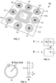
- moisture sensor 105 includes in part a resistor R, inductor (coil antenna) L, and capacitor C in a parallel ( FIG. 4, A ) or series ( FIG. 4, B ) resonant circuit configuration, also known as an RLC circuit as described in greater detail below.
- the capacitor element of the RLC moisture sensor circuit can operate as an electrochemical transducer to measure or determine wound moisture.
- an exemplary circular loop air coil antenna such as antenna 110 of reader 120, is shown in top (A) and side (B) views.
- the coil antenna can be a multi-layer coil antenna to form an inductance coil in limited space for wirelessly interrogating the one or more moisture sensors 105 of coupon 101.
- the at least one sensor 105 can be wirelessly interrogated by an electromagnetic field whose parameters depend at least in part on the physical design of the antenna, namely: an electric current I passing through the antenna coil, the antenna average radius r, the number of turns N in the antenna coil, the read-distance x along the central axis of the coil, the coil winding thickness t and coil winding height h.
- the electromagnetic field created by antenna 110 induces a current and a potential drop in the at least one moisture sensor 105 of coupon 101.
- the antenna coil includes N turns, where r is the average radius of the coil, t is the winding thickness and h is the winding height.
- each moisture sensor circuit can possess a characteristic (or resonant) frequency f and bandwidth B.
- f characteristic (or resonant) frequency
- bandwidth B bandwidth B
- the bandwidth, resonant frequency, and complex impedance Z of the RLC circuit of sensor 105 is dependent upon a capacitance value, which itself is dependent upon a moisture level of the environment surrounding the at least one sensor 105.
- a change in the moisture level of the surrounding environment can cause a corresponding, measurable shift and damping of the resonant frequency of the RLC resonator.
- the solid line shows sensor resonant impedance as a function of frequency.
- the bandwidth B of the sensor 105 circuit can be defined as the range between the peak of the maximum and minimum resonant values.
- the point corresponding to the lower frequency at half-power is f L , and referred to as the lower cut-off frequency with the point corresponding to the upper cut-off frequency as f H .
- the range between f H and f L can represent the bandwidth B as illustrated.
- the dashed line illustrates a shift and damping of the resonant impedance as a function of frequency (i.e., bandwidth) for a sensor 105 in a moist environment, where the complex impedance Z is given by the range between minimum and maximum values.
- a shift can be detected and analyzed, e.g., by microcontroller 130 of reader 120 as an impedance reflected in the antenna 110. This phenomenon can be exploited for qualifying and quantifying moisture levels of a wound bed when the sensor 105 is placed on or adjacent thereto.
- each moisture sensor 105 is configured as an RLC resonator circuit.
- the moisture sensor 105 includes a four-element electrode array (electrodes 107a-d) that together form a moisture transducer 106 and which acts as the capacitor in the RLC circuit.
- each electrode e.g., each of electrodes 107a-d
- the electrode-to-electrode spacing is about 0.0793 cm (1/32 inch). While the electrode dimensions disclosed here are suitable to enable the instant embodiment, it should be understood that other electrode dimensions and configurations can be substituted according to preference or to achieve operational characteristics as desired.
- the RLC circuit of the moisture sensor 105 further includes a substantially C-shaped resistor element 108 and a substantially ring-shaped inductor element 109 that surrounds both the C-shaped resistor element 108 and moisture transducer 106 as illustrated.
- a circuit can be printed, e.g., on a polyester film having about a five millimeter thickness with silver conductive polymer ink such that the moisture transducer 106, resistor 108 and inductor element 109 have thicknesses of about 1 mm.
- Exemplary printable conductors suitable for use in this capacity are DuPont's 5007 or 5025 printable silver conductors sold by DuPont, Research Triangle Park, North Carolina, USA; screen-printable silver ink nos. 1210 and 6105 provided by Methode (Chicago, Illinois, USA); and product no. ECI 1005 provided by Henkel Electrical Materials, Irvine, California, USA.
- coupon 101 can include a plurality of moisture sensors 105 arranged as desired to achieve a preferred moisture sensor density across coupon 101.
- each individual moisture sensor is labeled S1-S8 to correspond with the discussion of moisture mapping that follows.
- a plurality of moisture sensors 105 are in electronic communication with (i.e., through circuit connections), the centrally-disposed antenna 110 as shown.
- each moisture sensor 105 of the coupon 101 can be configured to be individually readable by reader 120 for collecting wound moisture and exudate levels in an area adjacent to, or in contact with each individual sensor 105.
- each sensor 105 can be configured to have a unique, identifiable resonant impedance profile, e.g., a resonance pattern through control of each printed sensor circuit.
- each resonant impedance profile can be measured for each sensor of the plurality of sensors and correlatively stored in memory.
- Each sensor can be identified by, e.g., one or more of a unique resonant impedance waveform shape (e.g., the solid line illustrated in FIG.
- the resonant impedance waveform can be measured for each individual sensor and correlatively stored with a particular sensor, e.g., sensor S1, sensor S2, etc.
- each sensor 105 disposed on coupon 101 can be individually interrogated for a surrounding moisture level reading by modifying the transceiver output to match the characteristic resonant frequency of any selected sensor 105.
- microcontroller 130 can be configured to make such output modifications in a step-wise order to interrogate each sensor present on a coupon 101.
- a WMAS 100 can be configured as a ⁇ slotted Aloha' system where the activation of each sensor is delayed in a particular order, e.g., clockwise beginning with a sensor at the 12 o'clock position.
- the WMAS 100 can be configured to utilize a so-called ⁇ adaptive binary tree' protocol, where each sensor 105 is configured with a pre-programmed ID bit and is activated only when the wireless reader 120 transmits an initialization symbol and a matching bit ID or ID sequence.
- an integrated circuit can be disposed on the coupon 101 and configured such that activation energy transmitted by the reader 120 and received by antenna 110 is shunted to each sensor S1-S8 in a particular order.
- the integrated circuit can be configured to intercept the activation energy received by antenna 110, then shunt the activation energy to a first sensor S1, followed by a second, different sensor S2, and so on, until all sensors S1-S8 have been activated in a selected order. Each sensor reading can then be collectively used to create a moisture map.
- coupon 101 includes eight moisture sensors 105, labeled S1-S8; however, it should be understood that more or fewer moisture sensors can be used as preferred.
- the array of moisture sensors can be used for creating a map of wound moisture or exudate. In a preferred approach, such a map can be collected at selected intervals over a time period to monitor and manage acute and chronic wounds.
- moisture sensor 105 readings of coupon 101 can be obtained when reader 120 is activated to emit a PWM signal.
- the PWM signal can be received by antenna 110, and thereby generate an electromagnetic field coupling between the transceiver 125 and antenna 110 of the coupon 101.
- Microcontroller 130 can be configured to generate a regulated AC voltage signal that is applied to the transceiver 125 and, simultaneously, measure the corresponding impedance of the at least one coupon sensor 105 as AC frequency is varied.
- the resulting waveform which correlates impedance as a function of AC frequency (hereinafter referred to as an "I/F waveform"), includes at least three features from which a moisture determination can be made: 1) the overall shape of the I/F waveform; 2) the amplitude of the I/F waveform; and 3) the symmetry of the I/F waveform pulse, which in this approach reflects the balance between leading and falling edges of the I/F waveform.
- the amplitude, or overall height of the I/F waveform can be used to reliably indicate the amount of moisture present in the vicinity of a sensor 105, and wet/dry cycling.
- the shape and symmetry of a I/F waveform can furthermore provide detailed information on the properties and chemistry of the fluid environment, such as electrochemical impedance, pH level and chemical composition (e.g., electrolyte identification), among other information.
- the reader 120 can be configured to power and communicate with the coupon 101 using a time pulse method.
- the reader 120 initiates a scan to read coupon 101 moisture by generating a time series pulse of known amplitude, width, and duty cycle.
- the antenna 110 captures the RF pulse wave transmitted from the reader 120 and the reflected impedance of the moisture sensor 105 is then analyzed by a time response analyzer (TRA) module 133 in the reader 120.
- TRA time response analyzer
- the TRA module 133 can be an electronic circuit module configured to quantify the pulse symmetry of the reflected I/F waveform from the sensor 105, for example: 1) the overall shape of the I/F waveform, 2) the amplitude of the I/F waveform, and 3) the symmetry of the I/F pulse, which, in this approach can represent a balance between the leading and falling edges of the reflected I/F waveform.
- FIG. 8 shows scan pulse and reflected I/F waveforms (charts A-D) of WMAS 100 test data for a coupon 101 exposed to varying degrees of moisture.
- each set shows the reader 120 scan pulse waveform in the top chart, e.g., chart A1 and the reflected, or output signal I/F waveform from a sensor 105 in the bottom chart, e.g., in chart A2.
- chart A in this example, a coupon 101 was immersed in a tap water solution to represent a soaked wound bandage.
- the reflected I/F waveform A2 has a decreased amplitude but its bandwidth is substantially narrow, similar in magnitude to the scan pulse A1.
- the coupon was exposed to a damp environment by applying two drops (502.75 mililiter per drop corresponding to 1.7 ⁇ 10 -3 fluid ounces per drop) of tap water solution to a coupon 101.
- the resulting output I/F waveform B2 is broadened, e.g., measured at its full-width-half-maximum (FWHM) and shows a decreased amplitude compared to the scan pulse B1.
- FWHM full-width-half-maximum
- Charts C and D show the effect of the I/F waveform shape, e.g., amplitude and width at FWHM showing a progressive shift toward greater output signal amplitude with increasing dampness and, concurrently, a greater negative deviation or 'recovery' following the excitation pulse with increasing sensor dampness.
- a correlative look-up table or a predictive mathematical model can be constructed from standard samples such as those shown in the charts of FIG. 8 , so that dampness and other factors of a wound bandage can be accurately determined by the WMAS 100.
- the amplitude of an I/F waveform appears to be dependent at least in part on the degree of dampness of the coupon 101 (and sensor 105 environment).
- the shape of the I/F waveform in general, e.g., amplitude, inflection and deflection points and areas, pulse width and other factors can be used to qualify and quantify exudate levels on or near a wound bed as described herein.
- FIG. 9 a functional illustration of a WMAS 200 is shown according to one embodiment.
- wireless communication between the reader and coupon can be accomplished using a digital circuitry schema.
- coupon, moisture sensor(s), reader and computing device refer to the WMAS components in a general sense as previously described, notwithstanding the differences of the analog and digital components of the reader and coupon in each respective section of this disclosure.
- the coupon 201 and reader 220 of WMAS 200 are configured with circuitry and modules for supporting digital acquisition of moisture sensor readings and digital transmission of moisture readings and associated data from the coupon 201 to the reader 220.
- some circuit components including, but not limited to the moisture sensors 205 can be disposed on coupon 201 by a selected circuit-printing technique.
- a selected circuit-printing technique For example, copper etching, a technique commonly used in the production of RFID tags can be used.
- the technique of inkjet circuit printing can be used.
- the electronic circuitry of coupon 201 can be printed directly on the coupon substrate using, preferably, a bio-compatible ink such as a silver nanoparticle ink.
- Other integrated circuit elements, such as control module 170 described below can be adhered to, or integrated into the coupon substrate by known methods.
- coupon 201 includes a control module 170 which, in this embodiment can be a fully-operational system-on-a-chip (SoC) configured for near-field communications (NFC) between the coupon 201 and reader 220.
- SoC system-on-a-chip
- the control module 170 can function, in part, as a transceiver, similar to transceiver 125 discussed with respect to FIG. 2 .
- the circuitry of coupon 201 can be powered by energy transmitted from an antenna 120a of the reader 220.
- the coupon 201 can include a power module 169 configured to receive RF energy which can be in circuit communication with other components of the coupon 201 requiring energy to function.
- the coupon 201 can thusly be energized to engender one or more data measurements to be taken, such as one or more moisture level readings as described in greater detail below.
- the measurement data can be transmitted by coupon 201 to reader 220.
- the control module 170 can include a near-field communications module configured to transmit data from the coupon 201 to the reader 220.
- the reader 220 can supply energy to the control module 170 through electromagnetic coupling and the digital response from the coupon 201 can be transmitted through backscatter to the reader 220.
- this form of energy harvesting and data transfer is accomplished through electromagnetic induction between the reader 220 and the coupon 201.
- reader 220 can be configured in a similar fashion as a radio frequency identification (RFID) scanner.
- RFID radio frequency identification
- control module 170 includes an ISO15693 radio-frequency interface with coupon antenna 175.
- antenna 175 is a printed circuit disposed on a top side 102a of the coupon substrate 102 that is configured to harness energy transmitted by reader antenna 120a necessary to power circuitry, modules and any other components of the coupon 201 through inductive coupling. Accordingly, in this embodiment, the antenna 175 circuit is in electronic communication with at least the control module 170 and the power module 169.
- coupon 201 does not necessarily require an on-board, stored power source such as a battery or wired electrical connection to carry out the functions of the coupon 201 as described herein, although such a configuration could be used in an alternative embodiment.
- the wireless configuration described herein advantageously provides the wearer with the same type of unrestricted mobility as if he were wearing a regular wound dressing.
- control module 170 can be a stand-alone near-field communications sensor transponder such as the RF430FRL152H sensor transponder by Texas Instruments, Dallas, TX, USA.
- the sensor transponder can be in circuit communication with one or more moisture sensors 205, temperature sensor 173, and bacteria sensor 182 of the coupon 201.
- control module 170 can store and analyze moisture sensor data to interpret results, e.g., moisture map data (as described in greater detail below) can be tabulated and transmitted to the reader to be displayed for clinical interpretation.
- moisture sensor data can be stored and analyzed in the controller 130 of the reader 220.
- a shared processing routine can utilize both controllers 171, 130; e.g., the coupon processor 170 can perform moisture sensor data preprocessing, filtering and formatting and the reader controller 130 can perform display and post measurement signal processing, including linearizing moisture sensor data.
- control module 170 can include an integrated circuit microcontroller 171.
- Microcontroller 171 can be selected from available commercial sources according to preference to address desired performance characteristics, power consumption or other aspects of coupon 101 functionality.
- One exemplary, non-limiting microcontroller that can be used is the MSP430 ultra-low power, 16-bit microcontroller provided by Texas Instruments, Inc., Dallas, TX, USA.
- microcontroller 171 is in electronic communication with the modules, sub-modules and sensor circuitry of the coupon 201, and is programmable to collect measurements, e.g., moisture and bacteria sensor measurements, alone or concurrently, as described herein.
- Microcontroller 171 is also in signal communication with antenna 175, enabling sensor measurements to be transmitted to reader 220.
- control module 170 further includes a conversion sub-module 172 to convert digital data, e.g., moisture sensor data as described herein, to wireless signals according to a NFC standard codec.
- digital data e.g., moisture sensor data as described herein
- control module 170 further includes first (176) and second (177) memory modules that can be used, e.g., for storing executable software instructions for carrying out various data-collecting functions as described herein, such as collecting sensor measurements, and storing data associated with those measurements.
- the first memory module can be a 2KB non-volatile ferroelectric memory
- the second memory module can be an 8KB read-only memory (ROM).
- control module 170 can optionally include an electronic temperature sensor.
- the temperature sensor can be used, e.g., to linearize moisture sensor data.
- temperature measurements can be recorded and transmitted along with moisture sensor measurements.
- temperature and moisture sensor data can be cooperatively used to correlate with bacteria sensor 182 data to assess the impact of bacteria on moisture sensor readings and to model bacterial activity.
- coupon 201 further includes an analog front-end component 184.
- the analog front-end component includes a multiplexer 186 that is configured to allow controller 170 to excite and gather moisture measurements from one or more moisture sensor circuits 205 of the coupon.
- coupon 201 can include as many moisture sensor circuits as desired.
- moisture sensor array 180 includes a plurality of individual moisture sensors 205 which are each configured to operate as electrochemical transducers to measure wound moisture.
- controller 170 can be configured to excite and gather data for all moisture sensors 205 concurrently, individually or according to a predetermined pattern.
- each sensor 205 is configured as a stand-alone electrochemical transducer that is in signal communication with microcontroller 171 via analog multiplexer 186.
- each sensor 205 includes interdigitated electrodes 107a-d.
- direct multiplexing obviates the resistor R and inductor L sensor circuit elements used in the analog counterpart (see, e.g., FIG. 7 ).
- capacitance is used to model an impedance change which is correlatable to a moisture level across sensor electrodes 107a-d.
- the inductor L is used to model the transmitter and receiver antenna coupling, which through the waveform analysis discussed previously, can provide correlation to moisture levels across electrodes 107a-d ( FIG. 7 ).
- the analog front-end component 184 further includes an operational amplifier 188 as an interface to an electrochemical bacteria sensor 182.
- Bacteria sensor 182 can be used, e.g., to detect and quantify contamination of moisture sensors 205 from exudate due to proliferation of bacteria and onset of infection.
- bacteria sensor 182 is centrally disposed on bottom side 102a of the coupon substrate and includes a Ag/AgCl reference electrode 182a, and a carbon-based working (182b) and counter (182c) electrode.
- the influence of exudate on sensor 205 impedance can be quantified and corrected for by, e.g., modeling bacterial contamination.
- impedance 'interference' due to bacterial contamination is caused by two primary sources: the first being microbial metabolism, which alters the conductivity of the medium; the second is electrode interfacial impedance, results when the presence of bacteria changes the surface properties of the electrodes, which can affect the capacitance of the electrode/electrolyte interface.
- temperature sensor 173 can provide an additional modeling and measuring parameter to account for the temperature effect on electrode capacitance, metabolic behavior of bacteria, and evaporation
- wireless reader 220 includes a microcontroller 130 in electronic signal communication with antenna 120a, a communications module 135 and a user interface 140 which itself is in signal communication with an external display 136.
- display 136 is a touch-screen display device that allows a user to input information, control functionality of the reader, activate moisture sensor scans, etc.
- reader 220 can optionally include buttons, keyboards or other user-controllable input devices which are not shown in FIG. 9 for the sake of figure clarity.
- controller 130 is configured to emit a controllable activation signal, e.g., an RF signal from antenna 120a that provides sufficient energy to power energy-necessary components of coupon 201, e.g., controller 170, and to allow moisture sensor 205 measurements to be taken.
- a controllable activation signal e.g., an RF signal from antenna 120a that provides sufficient energy to power energy-necessary components of coupon 201, e.g., controller 170, and to allow moisture sensor 205 measurements to be taken.
- antenna 175 of coupon 201 is configured to receive the activation signal from reader 220 with minimal energy loss.
- each of the one or more moisture sensors 205 can be used to collect a moisture sensor reading which is then transmitted back to reader 220 via antenna 175.
- microcontroller 130 includes at least a processor, a memory, and electronic data and command storage capabilities, e.g., RAM or ROM for electronically storing instructions for activating the one or more moisture sensors 205 and receiving moisture sensor readings therefrom, preferably analyzing those data, and transmitting the moisture sensor reading results to the computing device 150.
- microcontroller 130 is in signal communication, e.g., through the use of an input/output port, with user interface 140.
- User interface 140 can include, without limitation, a screen for displaying information relating to the acquisition of moisture sensor data, moisture analysis results and related data, historical data, and other information.
- user interface 140 can include a touch-sensitive display screen 136 that provides the capability of entering user input, e.g., patient-identifying information, general system settings (date, time, interrogation frequency, etc.), computer network settings providing the capability of transmitting data from the WMAS 100 to a computer network, e.g., through the use of wired or wireless signal communications, activation buttons configured to initiate a wound moisture assessment, and other functions.
- microcontroller 130 is in signal communication with a communications module 135 that is configured to transmit moisture sensor readings to computing device 150.
- the communications module 135 can be configured to provide bidirectional, electronic communication between the WMAS 100 and the remote computing device 150 by any preferred wired or wireless communications protocol or standard, such as WIFI, BLUETOOTH, IR, etc.
- the communications module 135 communicates with remote computing device 150 using wireless antennas 145 and 155, respectively.
- the wireless reader 220 can be in the form of an RFID scanner gun which collects moisture sensor readings and transmits those data to computing device 150 so that they may be processed into a user-friendly format such as a wound moisture map.
- coupon 201 can be powered through electromagnetic induction with reader 220 RF emission at, e.g., NFC frequencies of 13.56 MHz or other chosen frequencies.
- the reader 220 can use NFC standard techniques to power and communicate with the coupon; in such a case, the reader 220 can be implemented with a smartphone or other standard NFC device.
- reader 220 can be configured to transmit moisture sensor measurements from coupon 101 to computing device 150. Communication between the reader 220 and computing device 150 can be accomplished by any preferred wired or wireless communications protocol or standard, such as Ethernet, WIFI, BLUETOOTH, IR, etc. In general, moisture sensor measurements need not be directly between the reader 220 and the computing device 150.
- reader 220 can be in signal communication with a wireless router, access point or other communications hub which directs the measurement traffic to computing device 150 via a computer network, such as a LAN or the Internet, by known methods as disclosed above.
- computing device 150 can be configured to display information relating to the acquisition of moisture sensor data, moisture analysis results and related data, historical data, and other information via a software package.
- reader 220 can be configured to allow the user to enter information, such as the user's name, a patient ID, location, bed number, wound location, date, time, wound interrogation frequency or other data through a programmable user interface.
- the user-supplied information can be transmitted along with moisture sensor measurements from the reader 220 to the computing device 150 and, for example, compiled to form a data set.
- the user interface can include a touch-sensitive display screen that provides the capability of entering user input, computer network settings providing the capability of transmitting data from the reader 220 to a computer network, e.g., through the use of wired or wireless signal communications, activation buttons configured to initiate a wound moisture assessment, and other functions.
- WMAS 100 can be utilized to create a wound moisture map 160 of a wound.
- a moisture map of the type described herein can reflect moisture sensor data whether obtained by the analog or digital schemas described herein.
- a wound moisture map 160 can be a graphical representation of the moisture levels of a wound, as measured in different areas of the wound by the sensors 105/205 of coupon 101/201.
- a wound moisture map 160 can help to ascertain wound moisture imbalance and, in a preferred approach, such a map can be collected at selected intervals over a time period to monitor and manage acute and chronic wounds.
- FIG. 11 shows a plurality of moisture maps 160 for first, second, third and fourth dressings taken at 4, 8, 16 and 24-hour time intervals.
- each labeled square S1-S8 represents a moisture level measured by a corresponding moisture sensor S1-S8 of coupon 101 illustrated in FIG. 7 .
- square 161 graphically depicts the measured moisture level of the wound corresponding to sensor S6 of coupon 101.
- moisture map 160 can be graphically displayed using a legend to indicate a qualitative or quantitative moisture sensor reading.
- each moisture map 160 graphically depicts moisture sensor readings according to a "Dry,” “Slightly Wet,” “Semi-Wet” and “Wet” legend scale.
- the legend scale can be selected according to preference to correlate to a quantitative moisture level as measured by the moisture sensors 105.
- moisture map 160 could display quantitative data that show actual moisture levels as measured by each sensor 105/205, which can be expressed in any desired measurement unit.
- a coupon 101/201 provides the ability to dispose one or more moisture sensors at the perimeter of a wound where moisture sensing can be critical to: 1) understand where undermining (e.g., deep tissue damage under the wound margin) is occurring; 2) interpreting where maceration exists or where the locations where the wound perimeter is too dry, which can limit blood flow and irrigation of the wound bed; 3) ascertaining the true border of the wound; 4) ascertaining where new tissue could be forming or where granulation of tissue (epithelialization) is occurring; and 5) ascertaining where, and if infection is present.
- undermining e.g., deep tissue damage under the wound margin
- FIG. 11 shows an array of moisture maps 160, each for a first through fourth dressing.
- the top-left moisture map 160 corresponds to a measurement of a first coupon 101 (which may, e.g., be integrated into a wound dressing) at the 4-hour interval, and indicates that the respective portions of a wound adjacent to sensors S1-S8 are dry.
- the reading for moisture sensor S6 indicates a slightly wet environment
- the reading for moisture sensor S6 continues to indicate a slightly wet environment and moisture sensor S4 indicates a semi-wet environment
- moisture sensor S6 indicates a dry environment while sensor S7 indicates a slightly wet environment
- sensors S4 and S3 indicate semi-wet and wet environments, respectively.
- the exemplary data shown in FIG. 11 illustrate how coupon 101/201 having an array of moisture sensors 105/205 can be used to monitor physiological changes in a wound bed over time; accordingly, these data can be used in caring for the wound or providing an alert that wound healing is occurring or not.
- the beneficial effects of a moist versus dry wound environment include: prevention of tissue dehydration and cell death, accelerated angiogenesis, increased breakdown of dad tissue and fibrin, e.g., peri capillary fibrin cuffs, and potentiating the interaction of growth factors with their target cells.
- the extrapolation of moisture sensor data can be calibrated according to preference so that the relative terms “wet” “slightly wet” “semi-wet” and “wet” can reflect different degrees of wound moisture or exudate in a moisture map.
- a complex wound such as a pressure ulcer being treated with a vacuum-assisted closure (VAC) device, for example, points of desiccation and alternatively areas of pooling of exudate may exist.
- VAC vacuum-assisted closure
- the WMAS 100/200 can identify these areas and allow caregivers or the patient himself to modify their care to optimize the moisture of the wound for proper healing.
- coupon 101/201 can be integrated into a protective wound dressing or bandage of any kind.
- coupon 101/201 can be disposed on one side of a protective dressing and configured such that it can be applied directly to a wound, such as, but not limited to a venous, arterial, pressure or diabetic wound.
- the coupon 101/201 can be integrated into a protective dressing such that it is disposed between top and bottom layers of the dressing.
- the dressing can provide at least one layer of protective material between the wound bed and the coupon 101/201.
- Some exemplary, non-limiting types of dressings that coupon 101/201 can be integrated with include: tape and foam dressings, where coupon 101/201 can be disposed between the foam layer and the cover layer; transparent films, where coupon 101/201 can be printed directly on the film window; gauze, where coupon 101/201 can be embedded therein or thereon; composites, where coupon 101/201 can be embedded in intermediary layer or printed on the cover layer; and alginate, where coupon 101/201 can be disposed therein or on a secondary dressing.
- an exudate anti-fouling layer can be integrated into the dressings to reduce the deleterious effects of exudate adherence and acidity build-up between the wound and the dressing. This is illustrated in FIG. 12 by the dashed line between the intermediary layer and the absorbent layer.
- the anti-fouling layer can be perforated to promote exudate diffusion therethrough; and, in one embodiment, the holes of the perforated layer can contain exudate filter material to minimize exudate contamination of the coupon 101/201 components.
Landscapes
- Health & Medical Sciences (AREA)
- Engineering & Computer Science (AREA)
- Life Sciences & Earth Sciences (AREA)
- Animal Behavior & Ethology (AREA)
- Epidemiology (AREA)
- Biomedical Technology (AREA)
- Heart & Thoracic Surgery (AREA)
- Vascular Medicine (AREA)
- Veterinary Medicine (AREA)
- Public Health (AREA)
- General Health & Medical Sciences (AREA)
- Signal Processing (AREA)
- Computer Networks & Wireless Communication (AREA)
- Nursing (AREA)
- Orthopedic Medicine & Surgery (AREA)
- Measuring And Recording Apparatus For Diagnosis (AREA)
Claims (20)
- Coupon (101, 201) pour un soin de plaie conçu pour une communication sans fil avec un émetteur-récepteur (125), comprenant :un substrat flexible (102) ayant une surface supérieure (102a) et une surface inférieure (102b) ;un circuit d'antenne (110) radiofréquence disposé sur ladite surface supérieure dudit substrat flexible, le circuit d'antenne radiofréquence étant conçu pour recevoir une énergie radiofréquence ; etau moins un circuit capteur d'humidité électrochimique (105) disposé sur ladite surface inférieure dudit substrat flexible, l'au moins un circuit capteur d'humidité électrochimique étant configuré pour être alimenté par l'énergie radiofréquence.
- Coupon selon la revendication 1, comprenant en outre un module de communications en champ proche disposé sur ladite surface supérieure dudit substrat flexible qui est en communication électronique avec ledit circuit d'antenne radiofréquence.
- Coupon selon la revendication 2, ledit module de communications en champ proche comprenant :un microcontrôleur (171) en communication par signal avec ledit circuit d'antenne radiofréquence et ledit au moins un circuit capteur d'humidité électrochimique ; etune mémoire (176, 177) pour stocker des fonctions logiques exécutables pour mesurer une valeur d'humidité d'un environnement proximal audit au moins un circuit capteur d'humidité électrochimique.
- Coupon selon la revendication 3, ledit module de communications en champ proche comprenant en outre :un multiplexeur (186) en communication par signal avec ledit microcontrôleur (171) et ledit au moins un circuit capteur d'humidité électrochimique ;un convertisseur de signal capable de convertir des signaux analogiques en signaux numériques et vice-versa ; etun capteur de température (173) optionnel.
- Coupon selon la revendication 2, comprenant en outre un capteur de bactéries (182) disposé sur ladite surface inférieure dudit substrat flexible qui est communication par signal avec ledit module de communications en champ proche.
- Coupon selon la revendication 2, ledit module de communications en champ proche étant configuré pour recevoir une puissance de fonctionnement en provenance d'une source radiofréquence externe qui est reçue par ledit circuit d'antenne radiofréquence.
- Système (100, 200) pour un soin de plaie conçu pour obtenir sans fil une mesure d'humidité, comprenant :un lecteur sans fil (120, 220) comprenant un émetteur-récepteur (125) configuré pour émettre et recevoir des signaux radiofréquence ; etun coupon (101, 201), comprenant :un substrat flexible (102) ayant une surface supérieure (102a) et une surface inférieure (102b) ;au moins un circuit capteur d'humidité électrochimique (105) disposé sur ladite surface inférieure dudit substrat flexible qui est configuré pour déterminer une valeur d'humidité ;un circuit d'antenne (110) disposé sur ladite surface supérieure dudit substrat flexible configuré pour au moins recevoir lesdits signaux radiofréquence en provenance dudit émetteur-récepteur et pour alimenter l'au moins un circuit capteur d'humidité électrochimique par énergie radiofréquence des signaux radiofréquence reçus ; etun microcontrôleur (171) en communication électronique avec ledit circuit d'antenne et ledit au moins un circuit capteur d'humidité électrochimique.
- Système selon la revendication 7, comprenant en outre un circuit capteur de bactéries (182) disposé sur ladite surface inférieure dudit substrat flexible et configuré pour être en communication électronique avec ledit microcontrôleur.
- Système selon la revendication 7, ledit microcontrôleur étant configuré pour obtenir ladite valeur d'humidité en provenance dudit au moins un circuit capteur d'humidité électrochimique.
- Système selon la revendication 9, ledit microcontrôleur étant configuré pour émettre sans fil ladite mesure d'humidité audit lecteur sans fil (120) via ledit circuit d'antenne.
- Système selon la revendication 7, ladite valeur d'humidité étant déterminée en obtenant une valeur de capacité dudit au moins un circuit capteur d'humidité électrochimique.
- Système selon la revendication 7, ledit coupon étant disposé sur, ou dans, un pansement ou un bandage.
- Système selon la revendication 7, ledit microcontrôleur étant configuré pour être alimenté par ledit signal radiofréquence émis par ledit émetteur-récepteur (125) dudit lecteur sans fil (120).
- Système selon la revendication 7, ledit coupon comprenant un ensemble de circuits capteurs d'humidité électrochimiques, chacun en communication par signal avec ledit microcontrôleur (171).
- Système selon la revendication 14, comprenant en outre un multiplexeur (186) en communication électronique avec ledit microcontrôleur (171) qui est configuré pour obtenir une valeur de capacité de chacun desdits circuits capteurs d'humidité électrochimiques.
- Système (100, 200) pour un soin de plaie conçu pour générer un plan d'humidité de plaie (160), comprenant :un coupon flexible (101, 201) présentant une surface supérieure (102a) et une surface inférieure (102b), ladite surface inférieure étant configurée pour être appliquée au moins en partie à une plaie ou un ulcère ;un circuit d'antenne (110) et un microcontrôleur (171) disposés sur ladite surface supérieure dudit coupon, ledit microcontrôleur étant en communication électronique avec ledit circuit d'antenne ; etune pluralité de circuits capteurs d'humidité électrochimiques (105) disposés sur ladite surface inférieure dudit coupon ;chaque circuit capteur d'humidité électrochimique de ladite pluralité de circuits capteurs d'humidité électrochimiques étant en communication électronique avec ledit microcontrôleur ; etledit circuit d'antenne étant conçu pour envoyer et recevoir des signaux radiofréquence vers et en provenance d'un émetteur-récepteur (125) radiofréquence à distance, respectivement, et la pluralité de circuits capteurs d'humidité électrochimiques étant conçus pour être alimentés par une énergie radiofréquence des signaux radiofréquence reçus.
- Système selon la revendication 16, comprenant en outre un capteur de bactéries (182) électrochimique disposé sur ladite surface inférieure dudit coupon qui est en communication électronique avec ledit microcontrôleur.
- Système selon la revendication 16, comprenant en outre un capteur de température (173) électronique disposé sur ladite surface inférieure qui est en communication électronique avec ledit microcontrôleur.
- Système selon la revendication 16, ledit microcontrôleur (171) étant configuré pour :recevoir des signaux de demande en provenance dudit émetteur-récepteur (125) via ladite antenne (110) ;demander, à ladite pluralité de circuits capteurs d'humidité électrochimiques dans une modalité sélective ou de groupe, une ou plusieurs mesures d'humidité de plaie ; etémettre lesdites mesures d'humidité vers ledit émetteur-récepteur via ladite antenne.
- Système selon la revendication 16, chaque circuit capteur d'humidité électrochimique de ladite pluralité de circuits capteurs d'humidité électrochimiques comprenant un ensemble d'électrodes interdigitées.
Applications Claiming Priority (4)
| Application Number | Priority Date | Filing Date | Title |
|---|---|---|---|
| DKPA201870403 | 2018-06-15 | ||
| DKPA201870400 | 2018-06-15 | ||
| DKPA201870397 | 2018-06-15 | ||
| PCT/DK2019/050036 WO2019238180A1 (fr) | 2018-06-15 | 2019-01-31 | Système et procédé d'évaluation d'humidité pour soins de plaie |
Publications (2)
| Publication Number | Publication Date |
|---|---|
| EP3806792A1 EP3806792A1 (fr) | 2021-04-21 |
| EP3806792B1 true EP3806792B1 (fr) | 2024-11-06 |
Family
ID=65516401
Family Applications (1)
| Application Number | Title | Priority Date | Filing Date |
|---|---|---|---|
| EP19706365.4A Active EP3806792B1 (fr) | 2018-06-15 | 2019-01-31 | Système et procédé d'évaluation d'humidité pour soins de plaie |
Country Status (4)
| Country | Link |
|---|---|
| US (1) | US12414881B2 (fr) |
| EP (1) | EP3806792B1 (fr) |
| CN (1) | CN112261923B (fr) |
| WO (1) | WO2019238180A1 (fr) |
Families Citing this family (38)
| Publication number | Priority date | Publication date | Assignee | Title |
|---|---|---|---|---|
| CA3066073A1 (fr) | 2017-06-23 | 2018-12-27 | Smith & Nephew Plc | Positionnement de capteurs pour la surveillance ou le traitement de plaie active(e) par capteurs |
| GB201804502D0 (en) | 2018-03-21 | 2018-05-02 | Smith & Nephew | Biocompatible encapsulation and component stress relief for sensor enabled negative pressure wound therapy dressings |
| EP3664859A2 (fr) | 2017-08-10 | 2020-06-17 | Smith & Nephew plc | Positionnement de capteurs pour la surveillance ou le traitement des plaies activé(e) par capteurs |
| WO2019048624A1 (fr) | 2017-09-10 | 2019-03-14 | Smith & Nephew Plc | Systèmes et procédés d'inspection d'encapsulation et de composants dans des pansements équipés de capteurs |
| GB201718870D0 (en) | 2017-11-15 | 2017-12-27 | Smith & Nephew Inc | Sensor enabled wound therapy dressings and systems |
| GB201804971D0 (en) | 2018-03-28 | 2018-05-09 | Smith & Nephew | Electrostatic discharge protection for sensors in wound therapy |
| GB201718859D0 (en) | 2017-11-15 | 2017-12-27 | Smith & Nephew | Sensor positioning for sensor enabled wound therapy dressings and systems |
| WO2019063481A1 (fr) | 2017-09-27 | 2019-04-04 | Smith & Nephew Plc | Détection de ph pour appareils de surveillance et de thérapie de plaie à pression négative |
| WO2019072531A1 (fr) | 2017-09-28 | 2019-04-18 | Smith & Nephew Plc | Neurostimulation et surveillance à l'aide d'un appareil de surveillance et de traitement de plaie activé par un capteur |
| WO2019094635A1 (fr) | 2017-11-09 | 2019-05-16 | 11 Health and Technologies Inc. | Système et procédé de surveillance de stomie |
| US11559438B2 (en) | 2017-11-15 | 2023-01-24 | Smith & Nephew Plc | Integrated sensor enabled wound monitoring and/or therapy dressings and systems |
| GB201814011D0 (en) | 2018-08-29 | 2018-10-10 | Smith & Nephew | Componet positioning and encapsulation for sensor enabled wound dressings |
| GB2592508B (en) | 2018-09-12 | 2022-08-31 | Smith & Nephew | Device, apparatus and method of determining skin perfusion pressure |
| EP3856104B1 (fr) | 2018-09-28 | 2025-08-06 | T.J.Smith And Nephew, Limited | Fibres optiques permettant la détection optique à travers des pansements de plaie |
| WO2020076607A1 (fr) | 2018-10-09 | 2020-04-16 | Hollister Incorporated | Appareil de stomie doté d'un circuit d'encre conductrice pour détection de fuite |
| EP4368155B1 (fr) | 2018-10-09 | 2026-03-18 | Hollister Incorporated | Appareillage stomique comprenant des capteurs thermiques |
| GB201816838D0 (en) | 2018-10-16 | 2018-11-28 | Smith & Nephew | Systems and method for applying biocompatible encapsulation to sensor enabled wound monitoring and therapy dressings |
| USD893514S1 (en) | 2018-11-08 | 2020-08-18 | 11 Health And Technologies Limited | Display screen or portion thereof with graphical user interface |
| GB201820927D0 (en) | 2018-12-21 | 2019-02-06 | Smith & Nephew | Wound therapy systems and methods with supercapacitors |
| WO2020157103A1 (fr) | 2019-01-30 | 2020-08-06 | Smith & Nephew Plc | Pansements et systèmes intégrés à des capteurs |
| GB201901242D0 (en) | 2019-01-30 | 2019-03-20 | Smith & Nephew | Optical sensing systems and methods for sensing enabled wound dressings and systems |
| JP7529681B2 (ja) | 2019-03-18 | 2024-08-06 | スミス アンド ネフュー ピーエルシー | センサ統合基板用設計ルール |
| EP3941346A1 (fr) | 2019-03-19 | 2022-01-26 | Smith & Nephew plc | Systèmes et procédés pour la mesure de l'impédance d'un tissu |
| EP4559442A3 (fr) | 2019-06-14 | 2025-06-18 | Hollister Incorporated | Système de détection de fuite pour appareil de stomie |
| GB201914443D0 (en) | 2019-10-07 | 2019-11-20 | Smith & Nephew | Sensor enabled negative pressure wound monitoring apparatus with different impedances inks |
| GB201918856D0 (en) | 2019-12-19 | 2020-02-05 | Smith & Nephew | Sensor integrated dressings and systems |
| GB202003203D0 (en) | 2020-03-05 | 2020-04-22 | Smith & Nephew | Sensor integrated dressings and systems |
| GB2609367B (en) | 2020-04-21 | 2024-09-25 | Smith & Nephew | Wound treatment management using augmented reality overlay |
| GB202007391D0 (en) | 2020-05-19 | 2020-07-01 | Smith & Nephew | Patient protection from unsafe electric current in sensor integrated dressings and systems |
| DK4158298T3 (da) | 2020-05-27 | 2025-08-18 | Hollister Inc | System til registrering af stomilækage |
| DK3968910T3 (da) * | 2020-07-15 | 2023-04-03 | Hollister Inc | Modstandssensor til identifikation af lækagesteder i stomisystemet |
| US12472085B2 (en) | 2020-07-24 | 2025-11-18 | Hollister Incorporated | Double-sided sensor device for ostomy leak detection system |
| JP2023545504A (ja) | 2020-10-15 | 2023-10-30 | コンバテック・テクノロジーズ・インコーポレイテッド | オストミーシステムおよび方法 |
| WO2023018376A2 (fr) * | 2021-08-12 | 2023-02-16 | National University Of Singapore | Système de surveillance de plaie et capteur associé |
| FR3127577B1 (fr) | 2021-09-30 | 2023-10-06 | Urgo Rech Innovation Et Developpement | Coupon pour dispositif médical avec capteur d’humidité, dispositif médical, système, et procédé correspondants. |
| CN113916947A (zh) * | 2021-10-18 | 2022-01-11 | 江苏创芯海微科技有限公司 | 基于柔性湿度传感器阵列的湿度信息识别系统及方法 |
| CN116327291A (zh) * | 2023-03-16 | 2023-06-27 | 复旦大学附属中山医院 | 一种智能手术切口保持装置及方法 |
| USD1074482S1 (en) | 2023-06-28 | 2025-05-13 | Hollister Incorporated | Release liners for ostomy leak detection sensor |
Citations (3)
| Publication number | Priority date | Publication date | Assignee | Title |
|---|---|---|---|---|
| US20150018792A1 (en) * | 2012-01-30 | 2015-01-15 | Commissariat A L'energie Atomique Et Aux Energies Alternatives | Wound Dressing Provided with a Detection System |
| WO2017195038A1 (fr) * | 2016-05-13 | 2017-11-16 | Smith & Nephew Plc | Appareil de surveillance et de thérapie de plaie activé par un capteur |
| WO2018115461A1 (fr) * | 2016-12-22 | 2018-06-28 | Fleming Medical Ltd. | Système de pansement |
Family Cites Families (34)
| Publication number | Priority date | Publication date | Assignee | Title |
|---|---|---|---|---|
| US6433244B1 (en) | 1998-06-29 | 2002-08-13 | The Procter & Gamble Company | Disposable treatment article having a responsive system |
| US6720866B1 (en) | 1999-03-30 | 2004-04-13 | Microchip Technology Incorporated | Radio frequency identification tag device with sensor input |
| AU2002303198A1 (en) | 2001-03-30 | 2002-10-15 | Augmentech, Inc. | Patient incontinence/position monitoring apparatus and method of use thereof |
| US7612248B2 (en) * | 2002-12-19 | 2009-11-03 | 3M Innovative Properties Company | Absorbent medical articles |
| GB0408492D0 (en) | 2004-04-16 | 2004-05-19 | Univ Strathclyde | Performance measurement of wound dressings |
| US7570920B2 (en) | 2005-07-19 | 2009-08-04 | Intel Corporation | AM-FM hybrid signal communicated to RFID tags |
| CN101257845B (zh) * | 2005-09-02 | 2011-07-27 | 宝洁公司 | 指示皮肤含水量的方法和装置 |
| CN1808470A (zh) * | 2006-02-13 | 2006-07-26 | 上海中策工贸有限公司 | 尿片检测系统 |
| US7456744B2 (en) | 2006-05-16 | 2008-11-25 | 3M Innovative Properties Company | Systems and methods for remote sensing using inductively coupled transducers |
| CN101049261A (zh) | 2006-08-09 | 2007-10-10 | 上海中策工贸有限公司 | 医用纱布传感器系统 |
| US7948380B2 (en) | 2006-09-06 | 2011-05-24 | 3M Innovative Properties Company | Spatially distributed remote sensor |
| WO2009103034A2 (fr) | 2008-02-13 | 2009-08-20 | Board Of Regents, The University Of Texas System | Système, procédé et appareil pour détecteur de ph à film d'oxyde d'iridium amorphe |
| US20100022990A1 (en) | 2008-07-25 | 2010-01-28 | Boehringer Technologies, L.P. | Pump system for negative pressure wound therapy and improvements thereon |
| SE535589C2 (sv) * | 2010-07-12 | 2012-10-02 | Moelnlycke Health Care Ab | Sårförband innefattande ledande region |
| WO2012054474A1 (fr) | 2010-10-18 | 2012-04-26 | Avery Dennison Corporation | Dispositif de détection d'humidité rfid |
| EP2734166B8 (fr) | 2011-07-20 | 2018-08-15 | etectRx, Inc. | Capteurs d'humidité, système de surveillance d'humidité et procédés associés |
| CN202257867U (zh) * | 2011-07-29 | 2012-05-30 | 卓越进科技(深圳)有限公司 | 无线尿湿报警器及纸尿产品 |
| US8978452B2 (en) | 2011-08-11 | 2015-03-17 | 3M Innovative Properties Company | Wetness sensor using RF circuit with frangible link |
| US9393354B2 (en) | 2011-11-01 | 2016-07-19 | J&M Shuler Medical, Inc. | Mechanical wound therapy for sub-atmospheric wound care system |
| US9084530B2 (en) | 2012-04-12 | 2015-07-21 | Elwha Llc | Computational methods and systems for reporting information regarding appurtenances to wound dressings |
| US10158928B2 (en) | 2012-04-12 | 2018-12-18 | Elwha Llc | Appurtenances for reporting information regarding wound dressings |
| US10265219B2 (en) * | 2012-04-12 | 2019-04-23 | Elwha Llc | Wound dressing monitoring systems including appurtenances for wound dressings |
| US10226212B2 (en) | 2012-04-12 | 2019-03-12 | Elwha Llc | Appurtenances to cavity wound dressings |
| EP2866851B1 (fr) | 2012-06-28 | 2019-09-11 | KCI Licensing, Inc. | Tampon de liaison de plaie à dispositif d'identification par radiofréquence (rfid) et capteur de pression à extensomètre intégré |
| US20140276504A1 (en) * | 2013-03-13 | 2014-09-18 | Hill-Rom Services, Inc. | Methods and apparatuses for the detection of incontinence or other moisture, methods of fluid analysis, and multifunctional sensor systems |
| US9506886B1 (en) | 2014-04-30 | 2016-11-29 | Helvetia Wireless Llc | Systems and methods for detecting a liquid |
| CN203935329U (zh) * | 2014-05-28 | 2014-11-12 | 仲辉 | 一种医用纱布及其管理系统 |
| WO2016060938A2 (fr) | 2014-10-08 | 2016-04-21 | RF Micron, Inc. | Étiquette(s) et capteurs d'humidité d'identification par radiofréquence (rfid) présentant une détection étendue par l'intermédiaire de capillaires |
| EP3034054B1 (fr) | 2014-12-16 | 2021-01-20 | Absorbest AB | Pansement pourvu d'un capteur et son procédé de fabrication |
| US10702153B2 (en) * | 2015-04-15 | 2020-07-07 | King Abdullah University Of Science And Technology | Wound dressing with reusable electronics for wireless monitoring |
| TWM514624U (zh) * | 2015-08-13 | 2015-12-21 | Singli Technology Inc | 被照護者狀態判斷裝置及系統 |
| KR101942049B1 (ko) | 2016-03-29 | 2019-04-12 | 한국과학기술원 | 피에이치(pH) 센서, 무선전력전송 및 무선통신 기술을 이용한 창상 감염 모니터링용 스마트드레싱 및 스마트드레싱 시스템 |
| US9649230B1 (en) | 2016-08-17 | 2017-05-16 | Edward Li | Intelligent incontinence monitor |
| US11119053B2 (en) * | 2017-06-23 | 2021-09-14 | 3M Innovative Properties Company | Wireless sensing devices including stable near-field antenna |
-
2019
- 2019-01-31 EP EP19706365.4A patent/EP3806792B1/fr active Active
- 2019-01-31 US US17/252,291 patent/US12414881B2/en active Active
- 2019-01-31 CN CN201980039109.7A patent/CN112261923B/zh active Active
- 2019-01-31 WO PCT/DK2019/050036 patent/WO2019238180A1/fr not_active Ceased
Patent Citations (3)
| Publication number | Priority date | Publication date | Assignee | Title |
|---|---|---|---|---|
| US20150018792A1 (en) * | 2012-01-30 | 2015-01-15 | Commissariat A L'energie Atomique Et Aux Energies Alternatives | Wound Dressing Provided with a Detection System |
| WO2017195038A1 (fr) * | 2016-05-13 | 2017-11-16 | Smith & Nephew Plc | Appareil de surveillance et de thérapie de plaie activé par un capteur |
| WO2018115461A1 (fr) * | 2016-12-22 | 2018-06-28 | Fleming Medical Ltd. | Système de pansement |
Also Published As
| Publication number | Publication date |
|---|---|
| US12414881B2 (en) | 2025-09-16 |
| US20210267814A1 (en) | 2021-09-02 |
| CN112261923A (zh) | 2021-01-22 |
| CN112261923B (zh) | 2022-09-06 |
| EP3806792A1 (fr) | 2021-04-21 |
| WO2019238180A1 (fr) | 2019-12-19 |
Similar Documents
| Publication | Publication Date | Title |
|---|---|---|
| US12458278B2 (en) | Moisture assessment system and method for wound care | |
| EP3806792B1 (fr) | Système et procédé d'évaluation d'humidité pour soins de plaie | |
| O'Callaghan et al. | ‘Smart’wound dressings for advanced wound care: a review | |
| EP2739254B1 (fr) | Capteur d'humidité capacitif et procédé de fabrication associé | |
| EP2836269B1 (fr) | Procédure et système pour surveillance des pansements pour plaies | |
| US9451340B2 (en) | Computational methods and systems for reporting information regarding appurtenances to wound dressings | |
| US9510781B2 (en) | Dormant to active appurtenances for reporting information regarding wound dressings | |
| US10265219B2 (en) | Wound dressing monitoring systems including appurtenances for wound dressings | |
| US20190365571A1 (en) | A dressing system | |
| US20190254559A1 (en) | Implantable Sensor and Method for Such Sensor | |
| US20150087935A1 (en) | Real-time blood detection system | |
| SE534533C2 (sv) | Metod och system för detektering av fukt vid en absorberande artikel | |
| US20170340254A1 (en) | Real-time blood detection system | |
| US10357180B2 (en) | Health monitoring system | |
| WO2015084269A1 (fr) | Biocapteur implantable | |
| WO2014096973A2 (fr) | Systèmes et procédés de détection interne d'analytes | |
| US10405746B2 (en) | Wireless analog passive sensors |
Legal Events
| Date | Code | Title | Description |
|---|---|---|---|
| STAA | Information on the status of an ep patent application or granted ep patent |
Free format text: STATUS: UNKNOWN |
|
| STAA | Information on the status of an ep patent application or granted ep patent |
Free format text: STATUS: THE INTERNATIONAL PUBLICATION HAS BEEN MADE |
|
| PUAI | Public reference made under article 153(3) epc to a published international application that has entered the european phase |
Free format text: ORIGINAL CODE: 0009012 |
|
| STAA | Information on the status of an ep patent application or granted ep patent |
Free format text: STATUS: REQUEST FOR EXAMINATION WAS MADE |
|
| 17P | Request for examination filed |
Effective date: 20210115 |
|
| AK | Designated contracting states |
Kind code of ref document: A1 Designated state(s): AL AT BE BG CH CY CZ DE DK EE ES FI FR GB GR HR HU IE IS IT LI LT LU LV MC MK MT NL NO PL PT RO RS SE SI SK SM TR |
|
| AX | Request for extension of the european patent |
Extension state: BA ME |
|
| DAV | Request for validation of the european patent (deleted) | ||
| DAX | Request for extension of the european patent (deleted) | ||
| STAA | Information on the status of an ep patent application or granted ep patent |
Free format text: STATUS: EXAMINATION IS IN PROGRESS |
|
| 17Q | First examination report despatched |
Effective date: 20220310 |
|
| GRAP | Despatch of communication of intention to grant a patent |
Free format text: ORIGINAL CODE: EPIDOSNIGR1 |
|
| STAA | Information on the status of an ep patent application or granted ep patent |
Free format text: STATUS: GRANT OF PATENT IS INTENDED |
|
| INTG | Intention to grant announced |
Effective date: 20240529 |
|
| GRAS | Grant fee paid |
Free format text: ORIGINAL CODE: EPIDOSNIGR3 |
|
| GRAA | (expected) grant |
Free format text: ORIGINAL CODE: 0009210 |
|
| STAA | Information on the status of an ep patent application or granted ep patent |
Free format text: STATUS: THE PATENT HAS BEEN GRANTED |
|
| AK | Designated contracting states |
Kind code of ref document: B1 Designated state(s): AL AT BE BG CH CY CZ DE DK EE ES FI FR GB GR HR HU IE IS IT LI LT LU LV MC MK MT NL NO PL PT RO RS SE SI SK SM TR |
|
| REG | Reference to a national code |
Ref country code: GB Ref legal event code: FG4D |
|
| REG | Reference to a national code |
Ref country code: CH Ref legal event code: EP |
|
| REG | Reference to a national code |
Ref country code: DE Ref legal event code: R096 Ref document number: 602019061460 Country of ref document: DE |
|
| REG | Reference to a national code |
Ref country code: IE Ref legal event code: FG4D |
|
| P01 | Opt-out of the competence of the unified patent court (upc) registered |
Free format text: CASE NUMBER: APP_59793/2024 Effective date: 20241105 |
|
| REG | Reference to a national code |
Ref country code: LT Ref legal event code: MG9D |
|
| REG | Reference to a national code |
Ref country code: NL Ref legal event code: MP Effective date: 20241106 |
|
| PG25 | Lapsed in a contracting state [announced via postgrant information from national office to epo] |
Ref country code: IS Free format text: LAPSE BECAUSE OF FAILURE TO SUBMIT A TRANSLATION OF THE DESCRIPTION OR TO PAY THE FEE WITHIN THE PRESCRIBED TIME-LIMIT Effective date: 20250306 Ref country code: HR Free format text: LAPSE BECAUSE OF FAILURE TO SUBMIT A TRANSLATION OF THE DESCRIPTION OR TO PAY THE FEE WITHIN THE PRESCRIBED TIME-LIMIT Effective date: 20241106 Ref country code: PT Free format text: LAPSE BECAUSE OF FAILURE TO SUBMIT A TRANSLATION OF THE DESCRIPTION OR TO PAY THE FEE WITHIN THE PRESCRIBED TIME-LIMIT Effective date: 20250306 |
|
| PG25 | Lapsed in a contracting state [announced via postgrant information from national office to epo] |
Ref country code: FI Free format text: LAPSE BECAUSE OF FAILURE TO SUBMIT A TRANSLATION OF THE DESCRIPTION OR TO PAY THE FEE WITHIN THE PRESCRIBED TIME-LIMIT Effective date: 20241106 Ref country code: NL Free format text: LAPSE BECAUSE OF FAILURE TO SUBMIT A TRANSLATION OF THE DESCRIPTION OR TO PAY THE FEE WITHIN THE PRESCRIBED TIME-LIMIT Effective date: 20241106 |
|
| REG | Reference to a national code |
Ref country code: AT Ref legal event code: MK05 Ref document number: 1738578 Country of ref document: AT Kind code of ref document: T Effective date: 20241106 |
|
| PG25 | Lapsed in a contracting state [announced via postgrant information from national office to epo] |
Ref country code: BG Free format text: LAPSE BECAUSE OF FAILURE TO SUBMIT A TRANSLATION OF THE DESCRIPTION OR TO PAY THE FEE WITHIN THE PRESCRIBED TIME-LIMIT Effective date: 20241106 |
|
| PG25 | Lapsed in a contracting state [announced via postgrant information from national office to epo] |
Ref country code: ES Free format text: LAPSE BECAUSE OF FAILURE TO SUBMIT A TRANSLATION OF THE DESCRIPTION OR TO PAY THE FEE WITHIN THE PRESCRIBED TIME-LIMIT Effective date: 20241106 |
|
| PG25 | Lapsed in a contracting state [announced via postgrant information from national office to epo] |
Ref country code: NO Free format text: LAPSE BECAUSE OF FAILURE TO SUBMIT A TRANSLATION OF THE DESCRIPTION OR TO PAY THE FEE WITHIN THE PRESCRIBED TIME-LIMIT Effective date: 20250206 |
|
| PG25 | Lapsed in a contracting state [announced via postgrant information from national office to epo] |
Ref country code: LV Free format text: LAPSE BECAUSE OF FAILURE TO SUBMIT A TRANSLATION OF THE DESCRIPTION OR TO PAY THE FEE WITHIN THE PRESCRIBED TIME-LIMIT Effective date: 20241106 Ref country code: GR Free format text: LAPSE BECAUSE OF FAILURE TO SUBMIT A TRANSLATION OF THE DESCRIPTION OR TO PAY THE FEE WITHIN THE PRESCRIBED TIME-LIMIT Effective date: 20250207 Ref country code: AT Free format text: LAPSE BECAUSE OF FAILURE TO SUBMIT A TRANSLATION OF THE DESCRIPTION OR TO PAY THE FEE WITHIN THE PRESCRIBED TIME-LIMIT Effective date: 20241106 |
|
| PG25 | Lapsed in a contracting state [announced via postgrant information from national office to epo] |
Ref country code: PL Free format text: LAPSE BECAUSE OF FAILURE TO SUBMIT A TRANSLATION OF THE DESCRIPTION OR TO PAY THE FEE WITHIN THE PRESCRIBED TIME-LIMIT Effective date: 20241106 |
|
| PG25 | Lapsed in a contracting state [announced via postgrant information from national office to epo] |
Ref country code: RS Free format text: LAPSE BECAUSE OF FAILURE TO SUBMIT A TRANSLATION OF THE DESCRIPTION OR TO PAY THE FEE WITHIN THE PRESCRIBED TIME-LIMIT Effective date: 20250206 |
|
| PG25 | Lapsed in a contracting state [announced via postgrant information from national office to epo] |
Ref country code: SM Free format text: LAPSE BECAUSE OF FAILURE TO SUBMIT A TRANSLATION OF THE DESCRIPTION OR TO PAY THE FEE WITHIN THE PRESCRIBED TIME-LIMIT Effective date: 20241106 |
|
| PG25 | Lapsed in a contracting state [announced via postgrant information from national office to epo] |
Ref country code: DK Free format text: LAPSE BECAUSE OF FAILURE TO SUBMIT A TRANSLATION OF THE DESCRIPTION OR TO PAY THE FEE WITHIN THE PRESCRIBED TIME-LIMIT Effective date: 20241106 |
|
| PG25 | Lapsed in a contracting state [announced via postgrant information from national office to epo] |
Ref country code: EE Free format text: LAPSE BECAUSE OF FAILURE TO SUBMIT A TRANSLATION OF THE DESCRIPTION OR TO PAY THE FEE WITHIN THE PRESCRIBED TIME-LIMIT Effective date: 20241106 |
|
| PG25 | Lapsed in a contracting state [announced via postgrant information from national office to epo] |
Ref country code: RO Free format text: LAPSE BECAUSE OF FAILURE TO SUBMIT A TRANSLATION OF THE DESCRIPTION OR TO PAY THE FEE WITHIN THE PRESCRIBED TIME-LIMIT Effective date: 20241106 |
|
| PG25 | Lapsed in a contracting state [announced via postgrant information from national office to epo] |
Ref country code: SK Free format text: LAPSE BECAUSE OF FAILURE TO SUBMIT A TRANSLATION OF THE DESCRIPTION OR TO PAY THE FEE WITHIN THE PRESCRIBED TIME-LIMIT Effective date: 20241106 |
|
| PG25 | Lapsed in a contracting state [announced via postgrant information from national office to epo] |
Ref country code: CZ Free format text: LAPSE BECAUSE OF FAILURE TO SUBMIT A TRANSLATION OF THE DESCRIPTION OR TO PAY THE FEE WITHIN THE PRESCRIBED TIME-LIMIT Effective date: 20241106 |
|
| PG25 | Lapsed in a contracting state [announced via postgrant information from national office to epo] |
Ref country code: IT Free format text: LAPSE BECAUSE OF FAILURE TO SUBMIT A TRANSLATION OF THE DESCRIPTION OR TO PAY THE FEE WITHIN THE PRESCRIBED TIME-LIMIT Effective date: 20241106 |
|
| REG | Reference to a national code |
Ref country code: DE Ref legal event code: R097 Ref document number: 602019061460 Country of ref document: DE |
|
| REG | Reference to a national code |
Ref country code: CH Ref legal event code: PL |
|
| PG25 | Lapsed in a contracting state [announced via postgrant information from national office to epo] |
Ref country code: SE Free format text: LAPSE BECAUSE OF FAILURE TO SUBMIT A TRANSLATION OF THE DESCRIPTION OR TO PAY THE FEE WITHIN THE PRESCRIBED TIME-LIMIT Effective date: 20241106 |
|
| PLBE | No opposition filed within time limit |
Free format text: ORIGINAL CODE: 0009261 |
|
| STAA | Information on the status of an ep patent application or granted ep patent |
Free format text: STATUS: NO OPPOSITION FILED WITHIN TIME LIMIT |
|
| PG25 | Lapsed in a contracting state [announced via postgrant information from national office to epo] |
Ref country code: LU Free format text: LAPSE BECAUSE OF NON-PAYMENT OF DUE FEES Effective date: 20250131 Ref country code: MC Free format text: LAPSE BECAUSE OF FAILURE TO SUBMIT A TRANSLATION OF THE DESCRIPTION OR TO PAY THE FEE WITHIN THE PRESCRIBED TIME-LIMIT Effective date: 20241106 |
|
| 26N | No opposition filed |
Effective date: 20250807 |
|
| PG25 | Lapsed in a contracting state [announced via postgrant information from national office to epo] |
Ref country code: BE Free format text: LAPSE BECAUSE OF NON-PAYMENT OF DUE FEES Effective date: 20250131 |
|
| PG25 | Lapsed in a contracting state [announced via postgrant information from national office to epo] |
Ref country code: CH Free format text: LAPSE BECAUSE OF NON-PAYMENT OF DUE FEES Effective date: 20250131 |
|
| REG | Reference to a national code |
Ref country code: BE Ref legal event code: MM Effective date: 20250131 |
|
| PG25 | Lapsed in a contracting state [announced via postgrant information from national office to epo] |
Ref country code: IE Free format text: LAPSE BECAUSE OF NON-PAYMENT OF DUE FEES Effective date: 20250131 |
|
| PGFP | Annual fee paid to national office [announced via postgrant information from national office to epo] |
Ref country code: GB Payment date: 20260127 Year of fee payment: 8 |
|
| PGFP | Annual fee paid to national office [announced via postgrant information from national office to epo] |
Ref country code: DE Payment date: 20260128 Year of fee payment: 8 |
|
| PGFP | Annual fee paid to national office [announced via postgrant information from national office to epo] |
Ref country code: FR Payment date: 20260126 Year of fee payment: 8 |