EP3807012B1 - Zentrifuge - Google Patents
Zentrifuge Download PDFInfo
- Publication number
- EP3807012B1 EP3807012B1 EP19735218.0A EP19735218A EP3807012B1 EP 3807012 B1 EP3807012 B1 EP 3807012B1 EP 19735218 A EP19735218 A EP 19735218A EP 3807012 B1 EP3807012 B1 EP 3807012B1
- Authority
- EP
- European Patent Office
- Prior art keywords
- locking
- locking element
- drive shaft
- bearing
- rotor
- Prior art date
- Legal status (The legal status is an assumption and is not a legal conclusion. Google has not performed a legal analysis and makes no representation as to the accuracy of the status listed.)
- Active
Links
Images



Classifications
-
- B—PERFORMING OPERATIONS; TRANSPORTING
- B04—CENTRIFUGAL APPARATUS OR MACHINES FOR CARRYING-OUT PHYSICAL OR CHEMICAL PROCESSES
- B04B—CENTRIFUGES
- B04B9/00—Drives specially designed for centrifuges; Arrangement or disposition of transmission gearing; Suspending or balancing rotary bowls
- B04B9/08—Arrangement or disposition of transmission gearing ; Couplings; Brakes
-
- B—PERFORMING OPERATIONS; TRANSPORTING
- B04—CENTRIFUGAL APPARATUS OR MACHINES FOR CARRYING-OUT PHYSICAL OR CHEMICAL PROCESSES
- B04B—CENTRIFUGES
- B04B7/00—Elements of centrifuges
- B04B7/02—Casings; Lids
-
- B—PERFORMING OPERATIONS; TRANSPORTING
- B04—CENTRIFUGAL APPARATUS OR MACHINES FOR CARRYING-OUT PHYSICAL OR CHEMICAL PROCESSES
- B04B—CENTRIFUGES
- B04B9/00—Drives specially designed for centrifuges; Arrangement or disposition of transmission gearing; Suspending or balancing rotary bowls
- B04B9/12—Suspending rotary bowls ; Bearings; Packings for bearings
-
- B—PERFORMING OPERATIONS; TRANSPORTING
- B04—CENTRIFUGAL APPARATUS OR MACHINES FOR CARRYING-OUT PHYSICAL OR CHEMICAL PROCESSES
- B04B—CENTRIFUGES
- B04B7/00—Elements of centrifuges
- B04B7/02—Casings; Lids
- B04B2007/025—Lids for laboratory centrifuge rotors
-
- B—PERFORMING OPERATIONS; TRANSPORTING
- B04—CENTRIFUGAL APPARATUS OR MACHINES FOR CARRYING-OUT PHYSICAL OR CHEMICAL PROCESSES
- B04B—CENTRIFUGES
- B04B9/00—Drives specially designed for centrifuges; Arrangement or disposition of transmission gearing; Suspending or balancing rotary bowls
- B04B9/08—Arrangement or disposition of transmission gearing ; Couplings; Brakes
- B04B2009/085—Locking means between drive shaft and rotor
Definitions
- the invention relates to a centrifuge according to the type specified in the preamble of patent claim 1.
- Centrifuges with a removable rotor which have a device for axially locking the rotor on the drive shaft and which do not require complex assembly or special tools for locking.
- the DE 10 2014 112 501 A1 a generic centrifuge which has a drive shaft and a rotor mounted on the drive shaft and which can be removed axially in a removal direction.
- a quick-release fastener integrated into the rotor and the drive shaft is provided, by means of which the rotor can be fixed relative to the drive shaft in the removal direction.
- the quick-release fastener comprises an abutment in the drive shaft, into which the rotor engages with a locking part, and at least one locking element which, when activated, fixes the rotor relative to the drive shaft.
- the locking element acts between the locking part of the rotor and the abutment of the drive shaft.
- the quick-release fastener has a force transmission element.
- the locking element is operatively connected to an actuating element via the force transmission element.
- the quick-release fastener is unlocked by moving the actuating element, the force transmission element and the at least one locking element relative to the locking part in a direction along a straight line parallel to the longitudinal axis of the drive shaft.
- the actuating element moves in a direction along a straight line that runs parallel to the longitudinal axis of the drive shaft, towards the drive shaft.
- the force transmission element and the at least one locking element on one side and the locking part on the other side move relative to one another along a straight line that runs parallel to the longitudinal axis.
- the locking element is mounted so that it can pivot elastically via its solid-body joint.
- centrifuges Another problem with known centrifuges is that rotors with a low mass cannot lock themselves using their own weight, since the axial force required to deflect the locking elements is too large, which can lead to incorrect operation.
- the quick release has an actuating element that is pivoted about a horizontal axis.
- the actuating element also forms a locking bearing as a structural unit.
- the actuating element can therefore be rotated about the pivot axis.
- To unlock the actuating element must first be pressed, perpendicular to the drive axis, so that the actuating element is pivoted about the axis that is perpendicular to the drive shaft.
- the quick release as a whole with the rotor is then moved parallel to the drive axis, with a relative movement initially taking place between the quick release and the rotor. This creates further sources of error for wear and damage.
- the actuating element also has the locking bearing, this can only be operated with a great deal of force due to the clamping effect.
- the rotor is pressed and clamped onto the motor shaft by the spring force. This means that it is a force connection and not a form connection, which allows much higher locking forces.
- the user has to overcome the spring force to lock, which is why it is limited.
- a high spring force provides greater security against the rotor coming loose from the motor shaft. If the dynamic forces occurring during operation exceed the spring force, the system comes loose.
- the invention is therefore based on the object of developing a centrifuge according to the type specified in the preamble of claim 1 in such a way that it has a quick-change system that is reliable in continuous operation and in which only a small actuating force is required to insert the rotor.
- the locking function should be able to take place after the rotor has been placed on the drive shaft without additional effort using gravity alone, even with light rotors.
- the invention is based on the finding that this object can be achieved simply by pivoting the locking element from the locking position into an unlocking position and vice versa without elastic deformation and that this is most easily implemented by a normal joint acting about a horizontal pivot axis, i.e. not a solid-state joint, in particular by a hinge joint.
- the pivot axis of the locking joint is therefore aligned perpendicular to a straight line parallel to the longitudinal axis of the drive shaft, and the locking element is provided with a universal joint or bearing that can rotate about the pivot axis, the universal joint engaging in a bearing or the bearing enclosing a universal joint.
- the locking element is thus mounted in a simple manner via a hinge bearing. This makes it easy to reduce the force that needs to be applied, since, in contrast to a solid-state joint, there is no longer any elastic deformation, but only the friction of the universal joint in the bearing has to be overcome.
- a pivoting movement about a horizontally aligned pivot axis makes pivoting considerably easier than a vertically aligned pivot axis. This makes it possible to connect the rotor to the drive shaft purely by gravity, without any additional effort being necessary.
- the design options are increased.
- the universal joint shaft extends transversely to the longitudinal extension of the locking element and along the pivot axis of the locking element, about which the locking element is pivotably connected to the bearing.
- a relative movement takes place between the locking element with its universal joint shaft and the bearing.
- the bearing is part of a force transmission element which is operatively connected to the actuating element.
- the bearing can be designed as a radial bearing to enable easy production and to achieve high fatigue strength.
- the locking element has two cardan shaft areas perpendicular to its longitudinal extension, extending laterally to the longitudinal extension, each of which is assigned to an area of the bearing. Tilting due to one-sided bearing is thus avoided.
- the locking element has a locking area on one side in relation to the drive shaft area and a locking mass on the other side.
- the locking mass is preferably heavier than the locking area. This ensures that the locking mass is pushed outwards during operation of the centrifuge and at the same time the locking area of the locking element is pushed inwards and thus into the locking position. The safety of the quick release is thus increased.
- the centre of gravity of the locking element is located in the locking mass and there outside the intersection point of an axis along the longitudinal extension through the pivot axis in such a way that, when unlocking, a torque acts on the locking area of the locking element in the direction of the unlocking position.
- the locking area of the locking element is curved and/or adapted in terms of shape to the abutment and/or locking bearing. This enables a compact connection that is small in size.
- the locking element has a guide recess, in particular a U-shaped one, on its side remote from the free end. This reduces the loads on the bearing, particularly during load changes in the centrifuge.
- the force transmission element preferably has a guide that engages in the recess.
- the locking element is produced by powder injection molding, in particular metal powder injection molding - MIM -, by investment casting, by die casting, by cold forming, by plastic injection molding or by sintering. This makes it possible to produce locking elements that are both light and resistant to long-term loads.
- each locking element is designed identically to the other and arranged at an equal distance from the adjacent locking element. This ensures that the quick-release fastener does not create any imbalance when mounted with the drive shaft and the rotor.
- the force transmission element is spring-loaded in the direction of the locking position.
- the force transmission element can be designed as a cylindrical piston that is guided in a cylinder.
- the cylindrical piston can consist of several piston segments which are mounted so as to be movable relative to one another on a cylinder axis.
- a spring which acts on the cylindrical piston.
- several springs are provided, with one spring acting on a piston segment. This allows manufacturing tolerances to be compensated and ensures that the locking element is in flat contact with the abutment and locking bearing.
- the cylinder can be connected to the drive shaft so that the power transmission element is mounted on the drive shaft side. If the cylinder is connected to the rotor, the power transmission element is mounted on the rotor side.
- the actuating element moves toward or away from the drive shaft.
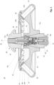
- Fig. 1 shows a schematic representation of a vertical section of a centrifuge according to the invention, designated overall by the reference number 10, with an angle rotor according to a first embodiment of the invention.
- the substructure is not shown, only the upper area of a drive shaft 12 is indicated schematically.
- a rotor 14 is arranged on the drive shaft 12.
- the centrifuge 10 comprises the vertically aligned cylindrical drive shaft 12 and the adapter 16 arranged on the drive shaft 12 and connected to the drive shaft 12 in a rotationally fixed manner.
- a concentrically arranged rotor hub 18 of the rotor 14 is mounted on the adapter 16.
- the adapter 16 and the rotor hub 18 and thus the drive shaft 12 and the rotor 14 are connected in a rotationally fixed manner in the manner explained below.
- the rotor 14 comprises a quick-release fastener 20.
- the rotor 14 is connected to the adapter 16 and thus to the drive shaft 12 via this quick-release fastener 20.
- the adapter 16 can also be designed as a unit with the drive shaft 12 and adapt the rotor hub 18 accordingly. Otherwise, the adapter 16 is optional. Alternatively, the drive shaft 12 can also be designed to directly accommodate the rotor hub 18.
- the outer contour 16a, 16b of the adapter 16 is essentially adapted to the inner profile of the rotor hub 18 and, viewed from a shoulder 16c, runs first in the form of a cone 16a tapering towards the top, then in the form of a cylinder 16b.
- the inner profile of the rotor hub 18 extends upwards beyond the free end of the cylindrical part of the outer contour 16b of the adapter 16 and then merges into a rotor central region 22 which is connected to the rotor hub 18 in a rotationally fixed manner.
- the rotor central region 22 has a locking part 24 which projects into the adapter 16 and has an outer contour whose diameter increases against the removal direction 26 first to a widest point 24a and then decreases.
- the region of the outer contour in which the circumference decreases against the removal direction 26 forms a control surface 24b, the function of which will be explained later.
- the locking part 24 is spaced from the inner contour of the adapter 16.
- a bore 24c which runs concentrically to a drive axis 28 is made in the locking part 24.
- the adapter 16 is provided centrally with a first cylindrical recess 30 and a second cylindrical recess 30 which is immediately adjacent to the top and has a wider diameter, resulting in an inner contour 32.
- the inner contour 32 is provided with a longer, higher section 32a, at the end of which on the rotor side a shoulder 32b is connected. This shoulder 32b is in turn connected to a shorter, lower section 32c with an inner diameter which is wider than the longer section 32a.
- the base of the cylindrical recess 30 rests on the drive shaft 12.
- a threaded screw 34 and pins (not shown here) connect the base to the drive shaft 12 at its front side.
- the drive shaft 12 and the adapter 16 are thereby connected to one another in a rotationally fixed manner.
- the shaft-side part of the quick release 20 Inside the adapter 16 above the bottom of the cylindrical recess 30 is the shaft-side part of the quick release 20.
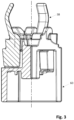
- This part comprises a Fig. 2 to 6 shown control unit 36, in which three locking elements 38 are each mounted in a radial bearing 40 and arranged at an equal distance from one another.
- the control unit 36 forms a piston 60, which is pushed in the removal direction by a spring 42 resting on the bottom of the cylindrical recess 30 26 is applied.
- the piston 60 can be moved along the longitudinal axis of the drive shaft 12, as will be explained further below.
- a support insert 44 is screwed into the section 32c of the adapter 16, which extends upwards over the free end of the section 32c and whose outer contour above the section 32c is adapted to the inner contour of the rotor central region 22.
- the support insert 44 has a bore 44a, which is dimensioned at the upper end so that the locking part 24 can pass through with its widest point 24a.
- the bore 44a widens conically towards the bottom and forms a support surface 44b, the function of which will be explained later.
- a removable cover 46 is arranged above the rotor 14 and forms a permanent structural unit with a handle 48.
- the handle 48 is fastened concentrically with the drive shaft 28 to the top of the cover 46, wherein a housing 50 of the handle 48 has a rotationally symmetrical outer contour and a cylindrical inner contour and a centrally arranged recess 46a of the cover 46, which extends through the latter.
- the rotor-side part of the quick-release fastener 20 is essentially arranged inside the handle 48. It comprises an actuating pin 52, the length of which is greater than the axial extent of the handle 48 and which, on the shaft side, passes through the locking part 24 in the bore 24c and comes into contact with a base area 36a of the control unit 36.
- the free end of the actuating pin 52 has an actuating button 52a. Unlocking takes place through the interaction of the handle 48 and the actuating button 52a.
- the actuating button 52a must be pressed, with the handle 48 serving as a counter bearing for the user, then the rotor 14 can be removed, in particular via the handle 48.
- Fig. 7 is in a section of a cross section along the central axis of the centrifuge 10 of Fig. 1
- the quick release 20 is shown in the unlocked state, but the rotor 14 is still placed on the adapter 16.
- the actuating pin 52 is pressed. This also causes the piston-shaped control unit 36, with the base area of which the actuating pin 52 is in stop on the shaft side, to be in the Locking space is displaced against the action of the spring 42 against the removal direction 26, which runs parallel to the longitudinal axis of the drive shaft 12.
- the locking elements 38 come to rest with their free ends on the control surface 24b of the locking part 24. They are then located outside their locking position between the locking part 24 and the abutment surface 44b.
- the pressure on the actuating pin 52 is released in the opposite direction to the removal direction 26.
- the rotor 14 is thereby moved into the locking position.
- the weight of the rotor 14 may be sufficient to move the rotor 14 into the locking position.
- the rotor With light rotors 14, the rotor may have to be pressed slightly into the locking position.
- the control unit 36 and thus also the locking elements 38 mounted in the control unit 36 are moved in the removal direction 26, i.e. along the longitudinal axis, due to the action of the spring 42 and counteract the weight of the rotor 14.
- the locking elements 38 slide along the control surface 24b of the locking part 24 of the rotor 14, past the widest point 24a into their locking position between the outer contour of the locking part 24 and the abutment surface 44b.
- the weight of the rotor 14 counteracts the locking elements 38 of the control unit 36 sliding over the control surface 24b.
- the locking elements 38 are deflected laterally, i.e. pivoted about a horizontal pivot axis 38b in order to pass the widest point 47a, but then do not return completely to their original orientation due to the center of gravity of the locking elements 38, as will be explained in more detail below, and again rest against the outer contour of the locking part 24 and the abutment surface 44b.
- the rotor 14 is now fixed in the centrifuge 10 in the axial direction, i.e. in the removal direction and in the opposite direction.
- Fig. 8 is in a section of a cross section along the central axis of the centrifuge 10 of Fig. 1
- the quick release fastener 20 is shown in the locked state.
- the actuating pin 52 is here in the position into which it is automatically brought by the indirect action of the spring 42 when no pressure is exerted on it from the outside in the direction of the longitudinal axis of the drive shaft 12.
- the control unit 36 and the locking elements 38 mounted on the control unit 36 are located in the area of the locking space near the rotor due to the action of the spring 42 and the lack of pressure exerted by the actuating pin 52 in the direction of the drive shaft 12.
- the locking elements 38 are located is in its locking position between the outer contour of the locking part 24 and the abutment surface 44b.
- the quick release fastener 20 is locked.
- the locking element 38 consists of three piston segments 54, 56 and 58. All three piston segments 54, 56, 58 are constructed accordingly and form a piston 60 as a force transmission element.
- the piston 60 is mounted in the cylindrical recess 30 of the adapter 16.
- the spring 42 acts on the piston 60.
- the piston segments 54, 56, 58 are mounted so that they can be displaced relative to one another along the drive axis 28. This allows manufacturing tolerances to be compensated and it is achieved that the locking elements 38 are all effective in the locking position.
- the locking elements 38 are therefore all arranged at the same distance from one another.
- Each piston segment 54, 56, 58 is provided with a radial bearing 40 to enable pivoting about the horizontal pivot axis 38b and thus about a straight line running perpendicular to a parallel line running to the longitudinal axis of the drive shaft 12.
- the radial bearing 40 is formed by two bearing arms 40a and 40b, which partially surround a universal joint shaft 38a extending transversely to the longitudinal extension of the locking element 38.
- the universal joint shaft 38a extends along the horizontal pivot axis 38b of the locking element 38 and has two universal joint shaft areas on each side.
- the locking element 38 can pivot about this pivot axis 38b between an unlocking position, as shown in Fig. 7 shown, and a locking position as shown in Fig. 8 is shown.
- the locking element 38 is provided with a substantially rectangular locking mass 38c, above it with the locking region 38e.
- the pivot axis 38b extends perpendicular to a straight line parallel to the longitudinal axis of the drive shaft 12, and is thus aligned horizontally when the longitudinal axis of the drive shaft 12 is aligned vertically.
- the piston segment 54, 56, 58 each has a recess 62 adapted to the outer contour of the locking mass 38c.
- the recess 62 is designed such that the locking mass 38c is always located within the envelope of the piston 60 surrounding the cylinder segment, regardless of the pivot position of the locking element 38. As a result, the movement along the drive axis 28 of the piston 60 in the cylindrical recess 30 in the adapter 16 is not hindered, regardless of the pivot position of the locking element 38.
- the recess 62 has a rectangular projection 62a in the lower region, which extends into the recess 62. Accordingly, the blocking mass 38c has an associated U-shaped recess 38d adapted to the projection 62a.
- the locking area 38e is bent and adapted to the outer contour of the locking part 24.
- the locking mass 38c is heavier than the locking area 38e.
- the center of gravity S of the locking element 38 is arranged in the locking mass 38c and is therefore outside the intersection point of an axis along the longitudinal extension of the locking element 38 through the pivot axis 38b.
- the piston segment 54, 56, 58 is provided with a centrally arranged strut 64, which, together with the other piston segments 54, 56, 58, forms a cylindrical receptacle 66 for the actuating pin 52, see in particular Fig. 6 .
- a horizontal strut 68 which is connected to the vertical strut 64 and runs into the projection 62a, forms the contact surface 68a of the spring 42.
- the struts 64 and 68 stabilize the piston segment in 54, 56, 58.
- the vertical strut 64 serves with the side surfaces of the piston segment 54, 56, 58 as a guide surface with respect to the other, adjacent piston segments 54, 56, 58, which together form the piston 60, in order to enable a relative movement of the piston segments 54, 56, 58 to one another.
- the locking element 38 is produced by powder injection molding, in particular metal powder injection molding, by investment casting, by die casting, by cold forming, by plastic injection molding or by sintering.
- the locking element 38 comprises the bearing 40 and the piston segments 54, 56 and 58 comprise the universal joint shaft 38a.
- the locking element 38 with the bearing 40 is pivotable relative to the universal joint shaft of the piston segment.
- the piston segments 54, 56 are constructed in accordance with the previously described embodiment.
Landscapes
- Centrifugal Separators (AREA)
Description
- Die Erfindung betrifft eine Zentrifuge gemäß der im Oberbegriff des Patentanspruches 1 angegebenen Art.
- Es sind bereits Zentrifugen mit abnehmbarem Rotor bekannt, die eine Einrichtung zur axialen Verriegelung des Rotors auf der Antriebswelle aufweisen und bei denen zur Verriegelung keine aufwendige Montage und kein spezielles Werkzeug erforderlich sind.
- Zum Beispiel ist aus der
DE 10 2014 112 501 A1 eine gattungsgemäße Zentrifuge bekannt, welche eine Antriebswelle und einen auf der Antriebswelle gelagerten, axial in eine Entnahmerichtung abnehmbaren Rotor aufweist. Dabei ist ein in den Rotor und die Antriebswelle integrierter Schnellverschluss vorgesehen, mittels dessen der Rotor gegenüber der Antriebswelle in Entnahmerichtung fixierbar ist. Der Schnellverschluss umfasst ein Widerlager in der Antriebswelle, in das der Rotor mit einem Verriegelungsteil eingreift, und zumindest ein Sperrelement, welches bei seiner Aktivierung den Rotor relativ zur Antriebswelle festlegt. Das Sperrelement wirkt zwischen dem Verriegelungsteil des Rotors und dem Widerlager der Antriebswelle. Der Schnellverschluss weist ein Kraftübertragungselement auf. Das Sperrelement steht über das Kraftübertragungselement mit einem Betätigungselement in Wirkverbindung. Die Entriegelung des Schnellverschlusses erfolgt durch eine Bewegung des Betätigungselements, des Kraftübertragungselements und des zumindest einen Sperrelements relativ zum Verriegelungsteil in eine Richtung entlang einer Geraden parallel zur Längsachse der Antriebswelle. Während der Entriegelung erfolgt eine Bewegung des Betätigungselements in Richtung entlang einer Geraden, welche parallel zur Längsachse der Antriebswelle verläuft, auf die Antriebswelle zu. Während einer Verriegelung erfolgt eine Relativbewegung des Kraftübertragungselements und des zumindest einen Sperrelements auf der einen Seite und des Verriegelungsteil auf der anderen Seite in Richtung entlang einer Geraden, welche parallel zur Längsachse verläuft, aufeinander zu. Das Sperrelement ist über sein Festkörpergelenk elastisch verschwenkbar gelagert. Dadurch muss beim Einbringen des Rotors eine axiale Kraftkomponente erzeugt werden. Um eine möglichst geringe Kraft erzeugen zu müssen, muss entweder der Federweg am Sperrelement vergrößert werden, was einen größeren Bauraum mit sich bringt, oder die Materialstärke des Sperrelements verringert werden, was zur Folge hat, dass der Klemmbereich kleiner wird. Dadurch werden vor allem auch unter Berücksichtigung von Fertigungstoleranzen die Haltekraft und Betriebssicherheit des Schnellverschlusses herabgesetzt. Eine Möglichkeit dem entgegenzuwirken wäre, das Material im Klemmbereich des Sperrelementes aufzudicken. In der Praxis hat sich aber gezeigt, dass diese Bereiche im Dauerbetrieb brechen können. - Weiterhin ist ein Problem bei den bekannten Zentrifugen, dass sich Rotoren mit einer geringen Masse nicht über das Eigengewicht verriegeln können, da die notwendige axiale Kraft, um die Sperrelemente auszulenken, zu groß ist, was zu Fehlbedienungen führen kann.
- Aus der
DE 698 10 060 T2 ist eine Zentrifuge bekannt, bei der jedoch die Sperrelemente um vertikal ausgerichtete Schwenkachsen aufweisende Gelenke schwenkbar sind und der Verriegelungsmechanismus unterschiedlich ist. Diese Konstruktion hat sich als sehr schwergängig und fehleranfällig erwiesen. - Aus der
DE 27 22 322 A1 ist eine Zentrifuge mit einem Schnellverschluss bekannt. Der Schnellverschluss weist ein Betätigungselement auf, welches um eine horizontale Achse verschwenkt wird. Das Betätigungselement bildet dabei zugleich ein Verriegelungslager als Baueinheit. Das Betätigungselement ist somit um die Schwenkachse drehbar. Zum Entriegeln muss zunächst das Betätigungselement gedrückt werden, und zwar senkrecht zur Antriebsachse, sodass das Betätigungselement um die zur Antriebswelle senkrecht verlaufende Achse verschwenkt wird. Anschließend wird der Schnellverschlusses als Ganzes mit dem Rotor parallel zur Antriebsachse verfahren, wobei zunächst eine Relativbewegung zwischen dem Schnellverschlusses und dem Rotor stattfindet. Hierdurch werden weitere Fehlerquellen für Verschleiß und Beschädigung geschaffen. Nachdem das Betätigungselement auch das Verriegelungslager aufweist, ist dieses aufgrund der Klemmwirkung nur mit sehr hohem Kraftaufwand zu betätigen. Der Rotor wird von der Federkraft auf die Motorwelle gedrückt und verspannt. D. h. es handelt sich um einen Kraftschluss und nicht um einen Formschluss, welcher wesentlich höhere Verriegelungskräfte erlaubt. Der Anwender muss zum Verriegeln die Federkraft überwinden, weshalb diese begrenzt ist. Eine große Federkraft sorgt für mehr Sicherheit gegen Lösen des Rotors von der Motorwelle. Überschreiten die während des Betriebs auftretenden dynamischen Kräfte die Federkraft, so löst sich das System. - Der Erfindung liegt daher die Aufgabe zugrunde, eine Zentrifuge gemäß der im Oberbegriff des Anspruches 1 angegebenen Art derart weiterzubilden, dass diese ein dauerbetriebssicheres Schnellwechselsystem aufweist, bei dem nur noch eine geringe Betätigungskraft zum Einbringen des Rotors notwendig ist. Vorzugsweise soll die Verriegelungsfunktion nach dem Aufsetzen des Rotors auf der Antriebswelle ohne zusätzlichen Kraftaufwand nur über die Schwerkraft auch bei leichten Rotoren erfolgen können.
- Der Erfindung liegt die Erkenntnis zugrunde, dass diese Aufgabe einfach dadurch gelöst werden kann, wenn das Sperrelement ohne elastische Verformung aus der Sperrstellung in eine Entriegelungsstellung und vice versa geschwenkt werden kann und dies am einfachsten durch ein normales, um eine horizontale Schwenkachse wirksames Gelenk, also gerade kein Festkörpergelenk, umgesetzt wird, insbesondere durch ein Scharniergelenk.
- Nach der Erfindung ist daher die Schwenkachse des Sperrgelenks senkrecht zu einer zur Längsachse der Antriebswelle parallelen Geraden ausgerichtet und das Sperrelement mit einer um die Schwenkachse drehbaren Gelenkwelle oder Lager versehen, wobei die Gelenkwelle in ein Lager eingreift oder das Lager eine Gelenkwelle umfasst. Das Sperrelement ist somit auf einfache Weise über ein Scharnierlager gelagert. Hierdurch kann auf einfache Weise die aufzubringende Kraft reduziert werden, da gegenüber einem Festkörpergelenk nun keine elastische Verformung mehr stattfindet, sondern nur noch die Reibung der Gelenkwelle im Lager zu überwinden ist. Zudem erleichtert eine Verschwenkbewegung um eine horizontal ausgerichteten Schwenkachse gegenüber einer vertikal ausgerichteten Schwenkachse ein Verschwenken erheblich. Hierdurch ist es möglich, den Rotor rein über die Schwerkraft mit der Antriebswelle zu verbinden, ohne dass ein zusätzlicher Kraftaufwand notwendig ist. Zudem erhöhen sich die konstruktiven Gestaltungsmöglichkeiten.
- Gemäß einer Ausführungsform der Erfindung erstreckt sich die Gelenkwelle quer zur Längserstreckung des Sperrelements und entlang der Schwenkachse des Sperrelements, um welche das Sperrelement schwenkbar mit dem Lager verbunden ist. Bei Bewegen des Sperrelements um die Schwenkachse findet eine Relativbewegung zwischen dem Sperrelement mit seiner Gelenkwelle und dem Lager statt. Auf einfache Weise wird hierdurch eine elastische Verformung des Sperrelements vermieden.
- Vorzugsweise ist das Lager Teil eines Kraftübertragungselements, das mit dem Betätigungselement in Wirkverbindung ist.
- Das Lager kann als Radiallager ausgebildet sein, um eine einfache Fertigung zu ermöglichen und hohe Dauerbruchfestigkeit zu erreichen.
- Insbesondere weist dabei das Sperrelement senkrecht zu seiner Längserstreckung zwei seitlich zur Längserstreckung sich erstreckende Gelenkwellenbereiche auf, die jeweils einem Bereich des Lagers zugeordnet sind. Ein Verkanten durch eine einseitige Lagerung wird hierdurch vermieden.
- Um die Voraussetzungen für eine Verstärkung der Haltekraft in der Verriegelungsposition zu schaffen, weist das Sperrelement auf der einen Seite bezogen auf den Gelenkwellenbereich einen Sperrbereich auf und auf der anderen Seite eine Sperrmasse. Hierbei ist bevorzugt die Sperrmasse schwerer als der Sperrbereich. Dadurch wird erreicht, dass die Sperrmasse während des Betriebs der Zentrifuge nach außen gedrückt wird und gleichzeitig der Sperrbereich des Sperrelements nach innen und somit in die Sperrstellung gedrückt wird. Die Sicherheit des Schnellverschlusses wird dadurch erhöht.
- Dafür liegt insbesondere der Schwerpunkt des Sperrelements in der Sperrmasse und dort so außerhalb des Schnittpunkts einer Achse entlang der Längserstreckung durch die Schwenkachse, dass beim Entriegeln ein Drehmoment auf den Sperrbereich des Sperrelements in Richtung Entriegelungsstellung wirkt.
- Vorzugsweise ist der Sperrbereich des Sperrelements gebogen ausgebildet und/oder im Hinblick auf die Form an das Widerlager und/oder Verriegelungslager angepasst. Hierdurch wird eine kompakte Verbindung ermöglicht, welche klein baut.
- Gemäß einer Ausführungsform der Erfindung weist das Sperrelement auf seiner dem freien Ende entfernt gelegenen Seite eine, insbesondere U-förmig ausgebildete, Führungsausnehmung auf. Vor allem bei Lastwechseln in der Zentrifuge werden hierbei Belastungen auf das Lager abgemildert. Dafür weist das Kraftübertragungselement bevorzugt eine in die Ausnehmung eingreifende Führung auf.
- Gemäß einer Ausführungsform der Erfindung ist das Sperrelement durch Pulverspritzgießen, insbesondere Metallpulverspritzgießen - MIM -, durch Feingießen, durch Druckgießen, durch Kaltumformen, durch Kunststoffspritzgießen oder durch Sintern hergestellt. Hierdurch lassen sich sowohl leichte als auch dauerbelastungfeste Sperrelemente fertigen.
- Um die Haltesicherheit des Rotors in der Zentrifuge zu erhöhen, sind zumindest zwei Sperrelemente, bevorzugt drei Sperrelemente, vorgesehen, wobei jedes Sperrelement gleich dem anderen ausgebildet und in gleichmäßigen Abstand zum jeweils benachbarten Sperrelement angeordnet ist. Hierdurch wird gewährleistet, dass der Schnellverschluss im montierten Zustand mit der Antriebswelle und dem Rotor keine Unwucht bildet.
- Vorzugsweise ist das Kraftübertragungselement in Richtung der Verriegelungsposition federbelastet. Das Kraftübertragungselement kann als zylindrischer Kolben ausgebildet sein, der in einem Zylinder geführt ist.
- Der zylindrische Kolben kann dabei aus mehreren Kolbensegmenten bestehen, welche zu einer Zylinderachse relativ zueinander beweglich gelagert sind.
- Vorzugsweise ist eine Feder vorgesehen, welche auf den zylindrischen Kolben wirkt. Alternativ sind mehrere Federn vorgesehen, wobei eine Feder auf ein Kolbensegment wirkt. Hierdurch können Fertigungstoleranzen ausgeglichen werden und ein flächiger Kontakt des Sperrelements mit dem Widerlager und Verriegelungslager gewährleistet werden.
- Hierbei kann der Zylinder mit der Antriebswelle verbunden sein, so dass das Kraftübertragungselement antriebswellenseitig gelagert ist. Ist der Zylinder mit dem Rotor verbunden, ist das Kraftübertragungselement rotorseitig gelagert.
- Vorzugsweise erfolgt während der Entriegelung eine Bewegung des Betätigungselements in Richtung auf die Antriebswelle zu oder von der Antriebswelle weg.
- Weitere Vorteile, Merkmale und Anwendungsmöglichkeiten der vorliegenden Erfindung ergeben sich aus der nachfolgenden Beschreibung in Verbindung mit den in den Zeichnungen dargestellten Ausführungsbeispielen.
- In der Beschreibung, in den Ansprüchen und in der Zeichnung werden die in der unten aufgeführten Liste der Bezugszeichen verwendeten Begriffe und zugeordneten Bezugszeichen verwendet. In der Zeichnung bedeutet:
- Fig. 1
- eine Schnittansicht eines Winkelrotors mit Deckel und einer Antriebswelle entlang der Mittelachse der Zentrifuge nach einer ersten Ausführungsform der Erfindung;
- Fig. 2a
- eine erste perspektivische Seitenansicht eines Kraftübertragungselement mit drei Sperrelementen gemäß einer ersten Ausführungsform der Erfindung;
- Fig. 2b
- eine zweite perspektivische Seitenansicht des Kraftübertragungselements mit den drei Sperrelementen gemäß einer ersten Ausführungsform der Erfindung;
- Fig. 2c
- eine dritte perspektivische Ansicht von schräg oben des Kraftübertragungselements mit den drei Sperrelementen gemäß einer ersten Ausführungsform der Erfindung;
- Fig. 2d
- eine Draufsicht auf das Kraftübertragungselement mit den drei Sperrelementen gemäß einer ersten Ausführungsform der Erfindung;
- Fig. 3
- eine perspektivische Seitenansicht mit Teilschnitt gemäß der
Fig. 2a ; - Fig. 4a
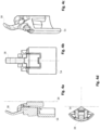
- eine Detailansicht im Schnitt eines Teils des Kraftübertragungselements mit dem Sperrelement gemäß der ersten Ausführungsform der Erfindung;
- Fig. 4b
- eine Seitenansicht des Teils des Kraftübertragungselements von
Fig. 4a ; - Fig. 4c
- eine perspektivische Ansicht von schräg oben des Teils des Kraftübertragungselements von
Fig. 4a ; - Fig. 4d
- eine Draufsicht auf das Teil des Kraftübertragungselements von
Fig. 4a ; - Fig. 5a
- eine Seitenansicht auf das Sperrelement gemäß der ersten Ausführungsform der Erfindung;
- Fig. 5b
- eine Vorderansicht auf das Sperrelement von
Fig. 5a ; - Fig. 5c
- eine perspektivische Ansicht von schräg oben auf das Sperrelement von
Fig. 5a ; - Fig. 5d
- eine Draufsicht auf das Sperrelement von
Fig. 5a ; - Fig. 6a
- eine Seitenansicht auf das Teil des Kraftübertragungselements ohne Sperrelement gemäß
Fig. 5a ; - Fig. 6b
- eine Vorderansicht des Teils des Kraftübertragungselements von
Fig. 6a ; - Fig. 6c
- eine perspektivische Ansicht von schräg oben auf das Teil des Kraftübertragungselements von
Fig. 6a ; - Fig. 6d
- eine Draufsicht auf das Teil des Kraftübertragungselements von
Fig. 6a ; - Fig. 7
- eine Schnittansicht des eingebauten Kraftübertragungselements mit Sperrelementen gemäß einer ersten Ausführungsform in der Entriegelungsposition, und
- Fig. 8
- eine Schnittansicht gemäß
Fig. 7 in der Verriegelungsposition. -
Fig. 1 zeigt in schematischer Darstellung einen vertikalen Schnitt einer insgesamt mit der Bezugsziffer 10 bezeichneten erfindungsgemäßen Zentrifuge mit einem Winkelrotor gemäß einer ersten Ausführungsform der Erfindung. Der Übersichtlichkeit halber ist die Unterkonstruktion nicht dargestellt, es wird nur der obere Bereich einer Antriebswelle 12 schematisch angedeutet. Auf der Antriebswelle 12 ist ein Rotor 14 angeordnet. - Nach dem in den Figuren dargestellten einem Ausführungsbeispiel umfasst die Zentrifuge 10 die vertikal ausgerichtete zylindrische Antriebswelle 12 und den auf der Antriebswelle 12 angeordneten und mit der Antriebswelle 12 drehfest verbundenen Adapter 16. Auf dem Adapter 16 ist eine konzentrisch angeordnete Rotornabe 18 des Rotors 14 aufgebracht. Der Adapter 16 und die Rotornabe 18 und somit die Antriebswelle 12 und der Rotor 14 sind drehfest in nachstehend erläuterter Weise verbunden. Der Rotor 14 umfasst einen Schnellverschluss 20. Über diesen Schnellverschluss 20 wird der Rotor 14 mit dem Adapter 16 und somit mit der Antriebswelle 12 verbunden.
- Der Adapter 16 kann konstruktiv auch in Einheit mit der Antriebswelle 12 ausgelegt werden und dementsprechend die Rotornabe 18 adaptieren. Im Übrigen ist der Adapter 16 optional. Alternativ kann auch die Antriebswelle 12 zur unmittelbaren Aufnahme der Rotornabe 18 ausgebildet sein.
- Die äußere Kontur 16a, 16b des Adapters 16 ist im Wesentlichen dem Innenprofil der Rotornabe 18 angepasst und verläuft von einem Absatz 16c aus betrachtet zuerst in Form eines sich nach oben hin verjüngenden Konus 16a, dann in Form eines Zylinders 16b.
- Das Innenprofil der Rotornabe 18 erstreckt sich über das freie Ende des zylindrischen Teils der äußeren Kontur 16b des Adapters 16 nach oben hinaus und geht dann in einen Rotorzentralbereich 22 über, welcher drehfest mit der Rotornabe 18 verbunden ist.
- Zur axialen Fixierung des Rotors 14 mit dem Adapter 16 und somit mit der Antriebswelle 12 weist der Rotorzentralbereich 22 ein in den Adapter 16 hineinragendes Verriegelungsteil 24 mit einer Außenkontur auf, deren Durchmesser entgegen der Entnahmerichtung 26 sich zuerst bis zu einer breitesten Stelle 24a vergrößert und dann abnimmt. Der Bereich der Außenkontur, in dem der Umfang entgegen der Entnahmerichtung 26 abnimmt, bildet eine Steuerfläche 24b, deren Funktion später erläutert wird. Das Verriegelungsteil 24 ist von der inneren Kontur des Adapters 16 beabstandet. Im Verriegelungsteil 24 ist eine konzentrisch zu einer Antriebsachse 28 verlaufende Bohrung 24c eingebracht.
- Der Adapter 16 ist zentrisch mit einer ersten zylindrischen und einer sich nach oben unmittelbar anschließenden, einen breiteren Durchmesser aufweisenden zweiten zylindrischen Ausnehmung 30 versehen, wodurch sich eine innere Kontur 32 ergibt. Die innere Kontur 32 ist mit einem, längeren, höheren Teilabschnitt 32a versehen, an dessen rotorseitigen Ende sich ein Absatz 32b anschließt. An diesen Absatz 32b schließt sich wiederum ein kürzerer, niedriger Teilabschnitt 32c mit einem gegenüber dem längeren Teilabschnitt 32a verbreiteten Innendurchmesser an.
- Der Boden der zylindrischen Ausnehmung 30 liegt auf der Antriebswelle 12 auf. Eine Gewindeschraube 34 und hier nicht dargestellte Stifte verbinden den Boden mit der Antriebswelle 12 an ihrer Stirnseite. Hierdurch sind die Antriebswelle 12 und der Adapter 16 drehfest miteinander verbunden.
- Innerhalb des Adapters 16 oberhalb des Bodens der zylindrischen Ausnehmung 30 befindet sich der wellenseitige Teil des Schnellverschlusses 20. Dieser Teil umfasst eine in
Fig. 2 bis 6 dargestellte Steuereinheit 36, in der drei Sperrelemente 38 jeweils in einem Radiallager 40 gelagert und in einem gleichen Abstand zueinander angeordnet sind. Die Steuereinheit 36 bildet einen Kolben 60, der von einer an dem Boden der zylindrischen Ausnehmung 30 anliegenden Feder 42 in die Entnahmerichtung 26 beaufschlagt ist. Der Kolben 60 kann entlang der Längsachse der Antriebswelle 12 bewegt werden, wie weiter unten noch erläutert wird. - In den Teilabschnitt 32c des Adapters 16 ist ein Widerlagereinsatz 44 eingeschraubt, der sich nach oben über das freie Ende des Teilabschnitts 32c erstreckt und dessen äußere Kontur oberhalb des Teilabschnitts 32c der inneren Kontur des Rotorzentralbereichs 22 angepasst ist. Der Widerlagereinsatz 44 weist eine Bohrung 44a auf, die am oberen Ende so bemessen ist, dass das Verriegelungsteil 24 mit seiner breitesten Stelle 24a passieren kann. Die Bohrung 44a verbreitert sich nach unten konisch und bildet eine Widerlagerfläche 44b aus, deren Funktion später erläutert wird.
- Die innere Kontur 32a, 32b, 32c des Adapters 16 bildet zusammen mit der Widerlagerfläche 44b des Widerlagereinsatzes 44 und, bei auf die Antriebswelle 12 aufgesetztem Rotor 14, der Außenkontur des Verriegelungsteils 24 die Begrenzung eines Verriegelungsraums, in dem die Verriegelung bzw. Entriegelung des Rotors 14 und somit die axiale Fixierung des Rotors 14 zur Antriebswelle 12 erfolgt.
- Oberhalb des Rotors 14 ist ein abnehmbarer Deckel 46 angeordnet, der mit einer Handhabe 48 eine unlösbare Baueinheit bildet. Die Handhabe 48 ist konzentrisch mit der Antriebsachse 28 an der Oberseite des Deckels 46 befestigt, wobei ein Gehäuse 50 der Handhabe 48 eine rotationssymmetrische Außenkontur und eine zylindrische Innenkontur aufweist und eine zentrisch angeordnete Ausnehmung 46a des Deckels 46, welche diesen durchgreift.
- Der rotorseitige Teil des Schnellverschlusses 20 ist im Wesentlichen im Inneren der Handhabe 48 angeordnet. Er umfasst einen Betätigungsstift 52, dessen Länge größer ist als die axiale Erstreckung der Handhabe 48 und der wellenseitig das Verriegelungsteil 24 in der Bohrung 24c durchgreift und mit einem Bodenbereich 36a der Steuereinheit 36 in Anlage kommt. Das freie Ende des Betätigungsstifts 52 weist einen Betätigungsknopf 52a auf. Im Zusammenwirken von Handhabe 48 und Betätigungsknopf 52a erfolgt die Entriegelung. Der Betätigungsknopf 52a muss gedrückt werden, wobei die Handhabe 48 dem Nutzer als Gegenlager dient, dann kann der Rotor 14 insbesondere über die Handhabe 48 entnommen werden.
- In
Fig. 7 ist in einem Ausschnitt aus einem Querschnitt entlang der Mittelachse der Zentrifuge 10 vonFig. 1 der Schnellverschluss 20 im entriegelten Zustand dargestellt, wobei der Rotor 14 aber noch auf dem Adapter 16 aufgesetzt ist. Der Betätigungsstift 52 ist gedrückt. Dadurch ist auch die kolbenförmige Steuereinheit 36, mit dessen Bodenbereich der Betätigungsstift 52 wellenseitig in Anschlag steht, im Verriegelungsraum gegen die Beaufschlagung der Feder 42 entgegen der Entnahmerichtung 26, welche parallel zur Längsachse der Antriebswelle 12 verläuft, verschoben. Die Sperrelemente 38 kommen in der vollständigen Entriegelungsstellung mit ihren freien Enden an der Steuerfläche 24b des Verriegelungsteils 24 zum Anliegen. Sie befinden sich dann außerhalb ihrer Sperrposition zwischen Verriegelungsteil 24 und Widerlagerfläche 44b. - Zur Verriegelung, siehe
Fig. 8 , wird der Druck auf den Betätigungsstift 52 entgegen der Entnahmerichtung 26 aufgehoben. Hierbei wird der Rotor 14 in die Verriegelungsstellung eingebracht. Die Gewichtskraft des Rotors 14 kann dabei ausreichen, den Rotor 14 in die Verriegelungsstellung einzubringen. Bei leichten Rotoren 14 muss ggfs. der Rotor etwas in Verriegelungsstellung gedrückt werden. Beim Aufsetzen des Rotors 14 werden die Steuereinheit 36 und damit auch die in der Steuereinheit 36 gelagerten Sperrelemente 38 auf Grund der Beaufschlagung durch die Feder 42 in Entnahmerichtung 26, also entlang der Längsachse, verfahren bzw. wirken der Gewichtskraft des Rotors 14 entgegen. Dabei gleiten die Sperrelemente 38 an der Steuerfläche 24b des Verriegelungsteils 24 des Rotors 14 entlang, vorbei an der breitesten Stelle 24a in ihre Sperrposition zwischen der Außenkontur des Verriegelungsteils 24 und der Widerlagerfläche 44b. Die Gewichtskraft des Rotors 14 wirkt den über die Steuerfläche 24b gleitenden Sperrelementen 38 der Steuereinheit 36 entgegen. - Für die Verriegelung werden die Sperrelemente 38 lateral ausgelenkt, also um eine horizontal verlaufende Schwenkachse 38b geschwenkt, um die breiteste Stelle 47a zu passieren, kehren dann aber aufgrund des Schwerpunktes der Sperrelemente 38, wie dies im Folgenden noch weiter erläutert wird, nicht ganz in ihre ursprüngliche Ausrichtung zurück und liegen wieder an der Außenkontur des Verriegelungsteils 24 und an der Widerlagerfläche 44b an. Der Rotor 14 ist nun in axialer Richtung, also in Entnahmerichtung und in die hierzu entgegengesetzte Richtung, in der Zentrifuge 10 fixiert.
- In
Fig. 8 ist in einem Ausschnitt aus einem Querschnitt entlang der Mittelachse der Zentrifuge 10 vonFig. 1 der Schnellverschluss 20 im verriegelten Zustand dargestellt. Im Gegensatz zur Darstellung in derFig. 7 befindet sich der Betätigungsstift 52 hier in der Position, in die er durch die mittelbare Beaufschlagung durch die Feder 42 selbsttätig gebracht wird, wenn kein Druck von außen in Richtung der Längsachse der Antriebswelle 12 auf ihn ausgeübt wird. Der Steuereinheit 36 und die auf der Steuereinheit 36 gelagerten Sperrelemente 38 befinden sich, bedingt durch die Beaufschlagung der Feder 42 und durch das Fehlen von durch den Betätigungsstift 52 in Richtung Antriebswelle 12 ausgeübten Drucks, im rotornahen Bereich des Verriegelungsraums. Die Sperrelemente 38 befinden sich in ihrer Sperrposition zwischen der Außenkontur des Verriegelungsteils 24 und Widerlagerfläche 44b. Der Schnellverschluss 20 ist verriegelt. - Wie insbesondere den
Fig. 2 bis 6 zu entnehmen ist, besteht das Sperrelement 38 aus drei Kolbensegmenten 54, 56 und 58. Alle drei Kolbensegmente 54, 56, 58 sind einander entsprechend aufgebaut und bilden einen Kolben 60 als Kraftübertragungselement. Der Kolben 60 ist in der zylindrischen Ausnehmung 30 des Adapters 16 gelagert. Auf den Kolben 60 wirkt die Feder 42. Die Kolbensegmente 54, 56, 58 sind zueinander entlang der Antriebsachse 28 relativ zueinander verschieblich gelagert. Hierdurch können Fertigungstoleranzen ausgeglichen werden und es wird erreicht, dass in der Verriegelungsstellung die Sperrelemente 38 alle wirksam sind. Die Sperrelemente 38 sind dadurch auch alle in einem gleichen Abstand zueinander angeordnet. - Jedes Kolbensegment 54, 56, 58 ist mit einem Radiallager 40 versehen, um ein Verschwenken um die horizontale Schwenkachse 38b und somit um eine senkrecht zu einer zur Längsachse der Antriebswelle 12 verlaufenden parallelen Geraden zu ermöglichen. Das Radiallager 40 wird durch zwei Lagerarme 40a und 40b gebildet, welche eine sich quer zur Längserstreckung des Sperrelements 38 erstreckende Gelenkwelle 38a bereichsweise umgreifen. Die Gelenkwelle 38a erstreckt sich entlang der horizontal verlaufenden Schwenkachse 38b des Sperrelements 38 und weist jeweils seitlich zwei Gelenkwellenbereiche auf. Um diese Schwenkachse 38b kann das Sperrelement 38 zwischen einer Entriegelungsstellung, wie sie in
Fig. 7 dargestellt ist, und einer Verriegelungsstellung, wie sie inFig. 8 dargestellt ist, verschwenken. Unterhalb der Gelenkwelle 38a ist das Sperrelement 38 mit einem im Wesentlichen rechteckigen Sperrmasse 38c versehen, oberhalb mit dem Sperrbereich 38e. Die Schwenkache 38b erstreckt sich dabei senkrecht zu einer zur Längsachse der Antriebswelle 12 parallelen Geraden, ist somit bei einer vertikalen Ausrichtung der Längsachse der Antriebswelle 12 horizontal ausgerichtet. - Das Kolbensegment 54, 56, 58 weist jeweils eine an die Außenkontur der Sperrmasse 38c angepasste Ausnehmung 62 auf. Die Ausnehmung 62 ist so gestaltet, dass sich der Sperrmasse 38c unabhängig von der Schwenkstellung des Sperrelements 38 immer innerhalb der das Zylindersegment Umhüllenden des Kolbens 60 befindet. Hierdurch wird die Bewegung entlang der Antriebsachse 28 des Kolbens 60 in der zylindrischen Ausnehmung 30 im Adapter 16 unabhängig von der Schwenkstellung des Sperrelements 38 nicht behindert.
- Die Ausnehmung 62 weist im unteren Bereich einen rechteckigen Vorsprung 62a auf, der sich in die Ausnehmung 62 hinein erstreckt. Entsprechend weist die Sperrmasse 38c eine zugeordnete und dem Vorsprung 62a angepasste U-förmige Ausnehmung 38d auf.
- Der Sperrbereich 38e ist gebogen und an die Außenkontur des Verriegelungsteils 24 angepasst.
- Die Sperrmasse 38c ist schwerer ausgebildet als der Sperrbereich 38e. Der Schwerpunkt S des Sperrelements 38 ist in der Sperrmasse 38c angeordnet und liegt somit außerhalb des Schnittpunkts einer Achse entlang der Längserstreckung des Sperrelements 38 durch die Schwenkachse 38b. Hierdurch wirkt beim Entriegeln ein Drehmoment auf den Sperrbereich 38e des Sperrelements 38 in Richtung Entriegelungsstellung. Beim Entriegeln, also beim Betätigen des Betätigungsstifts 52 und dem Verschieben des Kolbens 60 gegen die Kraft der Feder 42, verschwenkt somit das Sperrelement 38 um die horizontale Schwenkachse 38b aufgrund des anliegenden Drehmoments aus der Verriegelungsstellung in die Entriegelungsstellung.
- Das Kolbensegment 54, 56, 58 ist mit einer mittig angeordneten Strebe 64 versehen, welche mit den anderen Kolbensegmenten 54, 56, 58 aneinander anliegend eine zylindrische Aufnahme 66 für den Betätigungsstift 52 bilden, siehe hierzu insbesondere
Fig. 6 . Eine horizontale Strebe 68, welche mit der vertikalen Strebe 64 verbunden ist und in den Vorsprung 62a ausläuft, bildet die Anlagefläche 68a der Feder 42. Zudem stabilisieren die Streben 64 und 68 das Kolbensegment in 54, 56, 58. Die vertikale Strebe 64 dient mit den Seitenflächen des Kolbensegments 54, 56, 58 als Führungsfläche gegenüber den anderen, anliegenden Kolbensegmenten 54, 56, 58, welche zusammen den Kolben 60 bilden, um eine Relativbewegung der Kolbensegmente 54, 56, 58 zueinander zu ermöglichen. - Das Sperrelement 38 ist durch Pulverspritzgießen, insbesondere Metallpulverspritzgießen, durch Feingießen, durch Druckgießen, durch Kaltumformen, durch Kunststoffspritzgießen oder durch Sintern hergestellt.
- In einer hier nicht dargestellten alternativen Ausführungsform umfasst das Sperrelement 38 das Lager 40 und die Kolbensegmente 54, 56 und 58 umfassen die Gelenkwelle 38a. Das Sperrelement 38 mit dem Lager 40 ist relativ zur Gelenkwelle des Kolbensegments schwenkbar. Ansonsten sind die Kolbensegmente 54, 56 entsprechend der vorher beschriebenen Ausführungsform aufgebaut.
-
- 10
- Zentrifuge
- 12
- Antriebswelle
- 14
- Rotor
- 16
- Adapter
- 16a
- konischer Teil der äußeren Kontur des Adapters 16
- 16b
- zylindrischer Teil der äußeren Kontur des Adapters 16
- 16c
- Absatz der äußeren Kontur des Adapters 16
- 18
- Rotornabe
- 20
- Schnellverschluss
- 22
- Rotorzentralbereich
- 24
- Verriegelungsteil
- 24a
- breitester Teil der äußeren Kontur des Verriegelungsteils 24
- 24b
- Steuerfläche der äußeren Kontur des Verriegelungsteils 24
- 24c
- zentrische Bohrung im Verriegelungsteil 24
- 26
- Entnahmerichtung
- 28
- Antriebsachse
- 30
- zylindrische Ausnehmung im Adapter 16
- 32
- innere Kontur im Adapter 16
- 34
- Gewindeschraube
- 36
- Steuereinheit
- 38
- Sperrelement
- 38a
- Gelenkwelle
- 38b
- Schwenkachse
- 38c
- Sperrmasse
- 38d
- Ausnehmung im Sperrmasse 38c
- 38e
- Sperrbereich des Sperrelements 38
- 40
- Radiallager
- 40a
- Lagerarm, links
- 40b
- Lagerarm, rechts
- 42
- Feder
- 44
- Widerlagereinsatz
- 44a
- Bohrung im Widerlagereinsatz
- 44b
- Widerlagerfläche
- 46
- abnehmbarer Deckel
- 46a
- Ausnehmung im Deckel 46
- 48
- Handhabe
- 50
- Gehäuse der Handhabe 48
- 52
- Betätigungsstift
- 52a
- Betätigungsknopf des Betätigungsstiftes 52
- 54
- erstes Kolbensegment
- 56
- zweites Kolbensegment
- 58
- drittes Kolbensegment
- 60
- Kolben
- 62
- Ausnehmung
- 62a
- Vorsprung in der Ausnehmung 62
- 64
- Strebe
- 66
- zylindrische Aufnahme
- 68
- horizontale Strebe
- 68a
- Anlagefläche
- S
- Schwerpunkt des Sperrelements 38
Claims (16)
- Zentrifuge (10), aufweisenda) eine Antriebswelle (12), einen auf der Antriebswelle (12) gelagerten, axial in eine Entnahmerichtung (26) abnehmbaren Rotor (14),b) einen zwischen dem Rotor (14) und der Antriebswelle (12) wirksamen Schnellverschluss (20), mittels dessen der Rotor (14) gegenüber der Antriebswelle (12) in Entnahmerichtung (26) fixierbar ist,c) ein mit der Antriebswelle (12) verbundenes Widerlager (44),d) ein mit dem Rotor (14) verbundenes Verriegelungslager (24),e) zumindest ein Sperrelement (38), welches bei seiner Aktivierung den Rotor (14) relativ zur Antriebswelle (12) festlegt und zwischen dem Verriegelungslager (24) des Rotors (14) und dem Widerlager (44) der Antriebswelle (12) wirkt, wobei der Schnellverschluss (20) ein Betätigungselement (52) aufweist und das Sperrelement (38) mit dem Betätigungselement (52) so in Wirkverbindung steht, dass die Entriegelung des Schnellverschlusses (20) durch eine Bewegung des Betätigungselements (52) in eine Richtung parallel zur Längsachse der Antriebswelle (12) und durch eine Bewegung des Sperrelements (38) in eine Richtung parallel zur Längsachse der Antriebswelle (12) relativ zum Verriegelungslager (24) und/oder zum Widerlager (44) erfolgt, und dass während einer Verriegelung eine Relativbewegung des Sperrelements (38) auf der einen Seite und des Verriegelungslagers (24) und/oder des Widerlagers (44) auf der anderen Seite aufeinander zu in eine Richtung parallel zur Längsachse der Antriebswelle (12) erfolgen, wobei das Sperrelement (38) um eine Schwenkachse zumindest zwischen einer Sperrstellung und einer Entriegelungsstellung verschwenkbar ist, dadurch gekennzeichnet, dass die Schwenkachse (38b) senkrecht zu einer zur Antriebswelle (12) parallelen Geraden ausgerichtet ist und das Sperrelement (38) mit einer um die Schwenkachse (38b) drehbaren Gelenkwelle (38a) oder einem Lager (40) versehen ist, wobei die Gelenkwelle (38a) in ein Lager (40) eingreift oder das Lager (40) eine Gelenkwelle (38a) umfasst.
- Zentrifuge nach Anspruch 1, dadurch gekennzeichnet, dass die Gelenkwelle (38a) sich quer zur Längserstreckung des Sperrelements (38) und entlang der Schwenkachse (38b) des Sperrelements (38) erstreckt, um welche das Sperrelement (38) schwenkbar mit dem Lager (40) verbunden ist, und bei Bewegen des Sperrelements (38) um die Schwenkachse (38b) eine Relativbewegung zwischen dem Sperrelement (38) mit seiner Gelenkwelle (38a) und dem Lager (40) stattfindet.
- Zentrifuge nach Anspruch 1 oder 2, dadurch gekennzeichnet, dass das Lager (40) Teil eines Kraftübertragungselements (60) ist, das mit dem Betätigungselement (52) in Wirkverbindung ist und/oder das Lager (40) als Radiallager ausgebildet ist.
- Zentrifuge nach einem der vorangehenden Ansprüche, dadurch gekennzeichnet, dass das Sperrelement (38) senkrecht zu seiner Längserstreckung zwei seitlich zur Längserstreckung sich erstreckende Gelenkwellenbereiche (38a) aufweist, die jeweils einem Bereich des Lagers (40) zugeordnet sind.
- Zentrifuge nach einem der vorangehenden Ansprüche, dadurch gekennzeichnet, dass das Sperrelement (38) auf der einen Seite bezogen auf den Gelenkwellenbereich (38a) einen Sperrbereich (38e) aufweist und auf der anderen Seite eine Sperrmasse (38c).
- Zentrifuge nach Anspruch 5, dadurch gekennzeichnet, dass die Sperrmasse (38c) schwerer als der Sperrbereich (38e) ist und/oder die Sperrmasse (38c) während des Betriebs der Zentrifuge den Sperrbereich (38e) des Sperrelements (38) in die Sperrstellung drückt.
- Zentrifuge nach einem der Ansprüche 5 oder 6, dadurch gekennzeichnet, dass der Schwerpunkt (S) des Sperrelements (38) in der Sperrmasse (38c) so außerhalb des Schnittpunks einer Achse entlang der Längserstreckung durch die Schwenkachse (38b) liegt, dass beim Entriegeln ein Drehmoment auf den Sperrbereich (38e) des Sperrelements (38) in Richtung Entriegelungsstellung wirkt und/oder der Sperrbereich (38e) des Sperrelements (38) gebogen ausgebildet ist.
- Zentrifugen nach einem der Ansprüche 5 bis 7, dadurch gekennzeichnet, dass der Sperrbereich (38e) im Hinblick auf die Form an das Widerlager und/oder Verriegelungslager angepasst ist.
- Zentrifuge nach einem der Ansprüche 5 bis 8, dadurch gekennzeichnet, dass das Sperrmasse (38c) des Sperrelements (38) auf seiner dem freien Ende entfernt gelegenen Seite eine, insbesondere U-förmig ausgebildete, Führungsausnehmung (38d) aufweist.
- Zentrifuge nach Anspruch 3 und 8, dadurch gekennzeichnet, dass das Kraftübertragungselement (60) einen in die Ausnehmung eingreifenden Führungsvorsprung (62a) aufweist.
- Zentrifuge nach einem der vorangehenden Ansprüche, dadurch gekennzeichnet, dass das Sperrelement (38) durch Pulverspritzgießen, insbesondere Metallpulverspritzgießen - MIM -, durch Feingießen, durch Druckgießen, durch Kaltumformen, durch Kunststoffspritzgießen oder durch Sintern hergestellt ist.
- Zentrifuge nach einem der vorangehenden Ansprüche, dadurch gekennzeichnet, dass zumindest zwei Sperrelemente (38), bevorzugt drei Sperrelemente (38), vorgesehen sind, wobei jedes Sperrelement (38) gleich dem anderen ausgebildet ist und in gleichmäßigem Abstand zum jeweils benachbarten Sperrelement angeordnet ist.
- Zentrifuge nach einem der vorangehenden Ansprüche 3 bis 12, dadurch gekennzeichnet, dass das Kraftübertragungselement (60) in Richtung der Verriegelungsposition federbelastet ist.
- Zentrifuge nach einem der vorangehenden Ansprüche 3 bis 13, dadurch gekennzeichnet, dass das Kraftübertragungselement (60) als zylindrischer Kolben ausgebildet ist, der in einem Zylinder geführt ist, insbesondere dass der zylindrische Kolben (60) aus mehreren Kolbensegmenten (54, 56, 58) besteht, welche zu einer Zylinderachse relativ zueinander beweglich gelagert sind.
- Zentrifuge nach Anspruch 13 oder 14, dadurch gekennzeichnet, dass eine Feder (42) vorgesehen ist, welche auf den zylindrischen Kolben (60) wirkt oder mehrere Federn vorgesehen sind, wobei eine Feder auf ein Kolbensegment (54, 56, 58) wirkt.
- Zentrifuge nach einem der Ansprüche 13 bis 15, dadurch gekennzeichnet, dass der Zylinder mit der Antriebswelle (12) verbunden ist, so dass das Kraftübertragungselement (60) antriebswellenseitig gelagert ist oder der Zylinder mit dem Rotor (14) verbunden ist, so dass das Kraftübertragungselement (60) rotorseitig gelagert ist.
Applications Claiming Priority (2)
| Application Number | Priority Date | Filing Date | Title |
|---|---|---|---|
| DE102018114289.7A DE102018114289A1 (de) | 2018-06-14 | 2018-06-14 | Zentrifuge |
| PCT/EP2019/065255 WO2019238711A1 (de) | 2018-06-14 | 2019-06-11 | Zentrifuge |
Publications (2)
| Publication Number | Publication Date |
|---|---|
| EP3807012A1 EP3807012A1 (de) | 2021-04-21 |
| EP3807012B1 true EP3807012B1 (de) | 2025-02-12 |
Family
ID=67139687
Family Applications (1)
| Application Number | Title | Priority Date | Filing Date |
|---|---|---|---|
| EP19735218.0A Active EP3807012B1 (de) | 2018-06-14 | 2019-06-11 | Zentrifuge |
Country Status (7)
| Country | Link |
|---|---|
| US (1) | US11986842B2 (de) |
| EP (1) | EP3807012B1 (de) |
| JP (1) | JP7394075B2 (de) |
| KR (1) | KR102663294B1 (de) |
| CN (1) | CN112313011B (de) |
| DE (1) | DE102018114289A1 (de) |
| WO (1) | WO2019238711A1 (de) |
Families Citing this family (3)
| Publication number | Priority date | Publication date | Assignee | Title |
|---|---|---|---|---|
| DE102021121259A1 (de) | 2021-08-16 | 2023-02-16 | Andreas Hettich Gmbh & Co. Kg | Zentrifuge |
| CN113522540B (zh) * | 2021-09-13 | 2022-02-18 | 深圳市瑞沃德生命科技有限公司 | 一种转子及具有其的离心机 |
| EP4414085A1 (de) * | 2023-02-10 | 2024-08-14 | Thermo Electron LED GmbH | Rotor, rotorbefestigungsmechanismus, zentrifuge und zugehörige verfahren |
Citations (1)
| Publication number | Priority date | Publication date | Assignee | Title |
|---|---|---|---|---|
| DE2722322A1 (de) * | 1977-05-17 | 1978-11-30 | Compur Electronic Gmbh | Geraet zum trennen und messen von proben-bestandteilen |
Family Cites Families (7)
| Publication number | Priority date | Publication date | Assignee | Title |
|---|---|---|---|---|
| FR2770154B1 (fr) | 1997-10-23 | 1999-11-26 | Jouan | Centrifugeuse a rotor demontable et a dispositif de blocage axial du rotor sur une tete d'entrainement, et rotor pour une telle centrifugeuse |
| JP5442337B2 (ja) | 2009-06-30 | 2014-03-12 | 株式会社久保田製作所 | 遠心分離機、遠心分離機用ロータ |
| EP2698208A1 (de) | 2012-08-14 | 2014-02-19 | Fresenius Kabi Deutschland GmbH | Zentrifugenvorrichtung und Verfahren zum Betreiben einer Zentrifugenvorrichtung |
| DE102013107681B4 (de) | 2013-07-18 | 2018-02-08 | Andreas Hettich Gmbh & Co. Kg | Zentrifuge |
| DE102014112501B4 (de) | 2014-08-29 | 2017-07-27 | Andreas Hettich Gmbh & Co. Kg | Zentrifuge |
| DE102015113854A1 (de) | 2015-08-20 | 2017-02-23 | Andreas Hettich Gmbh & Co. Kg | Rotor einer Zentrifuge |
| DE102015113855A1 (de) * | 2015-08-20 | 2017-02-23 | Andreas Hettich Gmbh & Co. Kg | Rotor einer Zentrifuge |
-
2018
- 2018-06-14 DE DE102018114289.7A patent/DE102018114289A1/de not_active Withdrawn
-
2019
- 2019-06-11 JP JP2020569193A patent/JP7394075B2/ja active Active
- 2019-06-11 CN CN201980039696.XA patent/CN112313011B/zh active Active
- 2019-06-11 US US16/973,429 patent/US11986842B2/en active Active
- 2019-06-11 EP EP19735218.0A patent/EP3807012B1/de active Active
- 2019-06-11 WO PCT/EP2019/065255 patent/WO2019238711A1/de not_active Ceased
- 2019-06-11 KR KR1020217000202A patent/KR102663294B1/ko active Active
Patent Citations (1)
| Publication number | Priority date | Publication date | Assignee | Title |
|---|---|---|---|---|
| DE2722322A1 (de) * | 1977-05-17 | 1978-11-30 | Compur Electronic Gmbh | Geraet zum trennen und messen von proben-bestandteilen |
Also Published As
| Publication number | Publication date |
|---|---|
| JP2021526968A (ja) | 2021-10-11 |
| CN112313011A (zh) | 2021-02-02 |
| US20210245174A1 (en) | 2021-08-12 |
| KR20210020070A (ko) | 2021-02-23 |
| WO2019238711A1 (de) | 2019-12-19 |
| EP3807012A1 (de) | 2021-04-21 |
| DE102018114289A1 (de) | 2019-12-19 |
| JP7394075B2 (ja) | 2023-12-07 |
| US11986842B2 (en) | 2024-05-21 |
| KR102663294B1 (ko) | 2024-05-03 |
| CN112313011B (zh) | 2023-06-20 |
Similar Documents
| Publication | Publication Date | Title |
|---|---|---|
| EP2635380B1 (de) | Rotorlagerung für eine laborzentrifuge | |
| EP3186009B1 (de) | Schnellverschluss einer zentrifuge | |
| WO2017182228A1 (de) | Axialkugelgelenk und längeneinstellbarer zweipunktlenker mit einem solchen axialkugelgelenk | |
| EP0362566B1 (de) | Elastisches Lager | |
| EP3021974A1 (de) | Zentrifuge | |
| EP1217222B1 (de) | Toleranzausgleichselement | |
| WO2015113534A1 (de) | Nockenwellenverstärker | |
| DE19949654B4 (de) | Toleranzausgleichselement | |
| EP0275441B1 (de) | Spannvorrichtung | |
| AT393302B (de) | Vorrichtung zur verbindung zweier werkzeugteile | |
| WO2019238711A1 (de) | Zentrifuge | |
| EP1790437B1 (de) | Verfahren zum Einpressen eines auf einer Radnabe sitzenden Radlagers | |
| AT519652B1 (de) | Dichtungsvorrichtung und Hydraulikkolben mit Dichtungsvorrichtung | |
| EP1905545B1 (de) | Federspanner für Schraubenfedern | |
| DE102019206750B4 (de) | Vorrichtung zum Ausgleichen von Toleranzen zwischen einem ersten Bauteil und einem zweiten Bauteil | |
| DE2932248A1 (de) | Anordnung zum axialen fixieren und/oder anstellen von maschinenteilen | |
| DE10162910B4 (de) | Klemmspaltmutter | |
| EP4430313B1 (de) | Vorrichtung zur schwingungsgedämpften befestigung eines werkstücks | |
| EP3153279B1 (de) | Nach art einer spreizzange ausgebildetes handwerkzeug | |
| WO2004009276A1 (de) | Verbindung zweier maschinenteile | |
| EP2978564B2 (de) | Spannnest mit fixierelementen | |
| EP1715200B1 (de) | Kugelgelenkverbindung | |
| DE8702724U1 (de) | Türbeschlag | |
| DE8801499U1 (de) | Spannvorrichtung | |
| DE102016216604A1 (de) | Betätigungseinrichtung für ein Ausrücklager und Verfahren zu einer Vormontage desselben |
Legal Events
| Date | Code | Title | Description |
|---|---|---|---|
| STAA | Information on the status of an ep patent application or granted ep patent |
Free format text: STATUS: UNKNOWN |
|
| STAA | Information on the status of an ep patent application or granted ep patent |
Free format text: STATUS: THE INTERNATIONAL PUBLICATION HAS BEEN MADE |
|
| PUAI | Public reference made under article 153(3) epc to a published international application that has entered the european phase |
Free format text: ORIGINAL CODE: 0009012 |
|
| STAA | Information on the status of an ep patent application or granted ep patent |
Free format text: STATUS: REQUEST FOR EXAMINATION WAS MADE |
|
| 17P | Request for examination filed |
Effective date: 20210113 |
|
| AK | Designated contracting states |
Kind code of ref document: A1 Designated state(s): AL AT BE BG CH CY CZ DE DK EE ES FI FR GB GR HR HU IE IS IT LI LT LU LV MC MK MT NL NO PL PT RO RS SE SI SK SM TR |
|
| AX | Request for extension of the european patent |
Extension state: BA ME |
|
| RIN1 | Information on inventor provided before grant (corrected) |
Inventor name: EBERLE, KLAUS-GUENTER Inventor name: HEGELE, ROBERT Inventor name: PRILLA, RAINER Inventor name: HOELDERLE, ANDREAS Inventor name: HORNEK, MATTHIAS |
|
| DAV | Request for validation of the european patent (deleted) | ||
| DAX | Request for extension of the european patent (deleted) | ||
| REG | Reference to a national code |
Ref country code: DE Ref legal event code: R079 Free format text: PREVIOUS MAIN CLASS: B04B0009080000 Ipc: B04B0007020000 Ref country code: DE Ref legal event code: R079 Ref document number: 502019012916 Country of ref document: DE Free format text: PREVIOUS MAIN CLASS: B04B0009080000 Ipc: B04B0007020000 |
|
| GRAP | Despatch of communication of intention to grant a patent |
Free format text: ORIGINAL CODE: EPIDOSNIGR1 |
|
| STAA | Information on the status of an ep patent application or granted ep patent |
Free format text: STATUS: GRANT OF PATENT IS INTENDED |
|
| INTG | Intention to grant announced |
Effective date: 20240924 |
|
| RIC1 | Information provided on ipc code assigned before grant |
Ipc: B04B 9/08 20060101ALI20240916BHEP Ipc: B04B 7/02 20060101AFI20240916BHEP |
|
| GRAS | Grant fee paid |
Free format text: ORIGINAL CODE: EPIDOSNIGR3 |
|
| GRAA | (expected) grant |
Free format text: ORIGINAL CODE: 0009210 |
|
| STAA | Information on the status of an ep patent application or granted ep patent |
Free format text: STATUS: THE PATENT HAS BEEN GRANTED |
|
| AK | Designated contracting states |
Kind code of ref document: B1 Designated state(s): AL AT BE BG CH CY CZ DE DK EE ES FI FR GB GR HR HU IE IS IT LI LT LU LV MC MK MT NL NO PL PT RO RS SE SI SK SM TR |
|
| REG | Reference to a national code |
Ref country code: GB Ref legal event code: FG4D Free format text: NOT ENGLISH |
|
| REG | Reference to a national code |
Ref country code: DE Ref legal event code: R081 Ref document number: 502019012916 Country of ref document: DE Owner name: ANDREAS HETTICH GMBH, DE Free format text: FORMER OWNER: ANMELDERANGABEN UNKLAR / UNVOLLSTAENDIG, 80297 MUENCHEN, DE Ref country code: CH Ref legal event code: EP |
|
| REG | Reference to a national code |
Ref country code: IE Ref legal event code: FG4D Free format text: LANGUAGE OF EP DOCUMENT: GERMAN |
|
| REG | Reference to a national code |
Ref country code: DE Ref legal event code: R096 Ref document number: 502019012916 Country of ref document: DE |
|
| P01 | Opt-out of the competence of the unified patent court (upc) registered |
Free format text: CASE NUMBER: APP_15092/2025 Effective date: 20250327 |
|
| REG | Reference to a national code |
Ref country code: NL Ref legal event code: MP Effective date: 20250212 |
|
| PG25 | Lapsed in a contracting state [announced via postgrant information from national office to epo] |
Ref country code: RS Free format text: LAPSE BECAUSE OF FAILURE TO SUBMIT A TRANSLATION OF THE DESCRIPTION OR TO PAY THE FEE WITHIN THE PRESCRIBED TIME-LIMIT Effective date: 20250512 |
|
| PG25 | Lapsed in a contracting state [announced via postgrant information from national office to epo] |
Ref country code: FI Free format text: LAPSE BECAUSE OF FAILURE TO SUBMIT A TRANSLATION OF THE DESCRIPTION OR TO PAY THE FEE WITHIN THE PRESCRIBED TIME-LIMIT Effective date: 20250212 |
|
| PG25 | Lapsed in a contracting state [announced via postgrant information from national office to epo] |
Ref country code: PL Free format text: LAPSE BECAUSE OF FAILURE TO SUBMIT A TRANSLATION OF THE DESCRIPTION OR TO PAY THE FEE WITHIN THE PRESCRIBED TIME-LIMIT Effective date: 20250212 |
|
| PGFP | Annual fee paid to national office [announced via postgrant information from national office to epo] |
Ref country code: DE Payment date: 20250610 Year of fee payment: 7 |
|
| PG25 | Lapsed in a contracting state [announced via postgrant information from national office to epo] |
Ref country code: ES Free format text: LAPSE BECAUSE OF FAILURE TO SUBMIT A TRANSLATION OF THE DESCRIPTION OR TO PAY THE FEE WITHIN THE PRESCRIBED TIME-LIMIT Effective date: 20250212 |
|
| REG | Reference to a national code |
Ref country code: LT Ref legal event code: MG9D |
|
| PG25 | Lapsed in a contracting state [announced via postgrant information from national office to epo] |
Ref country code: IS Free format text: LAPSE BECAUSE OF FAILURE TO SUBMIT A TRANSLATION OF THE DESCRIPTION OR TO PAY THE FEE WITHIN THE PRESCRIBED TIME-LIMIT Effective date: 20250612 Ref country code: NO Free format text: LAPSE BECAUSE OF FAILURE TO SUBMIT A TRANSLATION OF THE DESCRIPTION OR TO PAY THE FEE WITHIN THE PRESCRIBED TIME-LIMIT Effective date: 20250512 |
|
| PG25 | Lapsed in a contracting state [announced via postgrant information from national office to epo] |
Ref country code: NL Free format text: LAPSE BECAUSE OF FAILURE TO SUBMIT A TRANSLATION OF THE DESCRIPTION OR TO PAY THE FEE WITHIN THE PRESCRIBED TIME-LIMIT Effective date: 20250212 |
|
| PG25 | Lapsed in a contracting state [announced via postgrant information from national office to epo] |
Ref country code: HR Free format text: LAPSE BECAUSE OF FAILURE TO SUBMIT A TRANSLATION OF THE DESCRIPTION OR TO PAY THE FEE WITHIN THE PRESCRIBED TIME-LIMIT Effective date: 20250212 |
|
| PG25 | Lapsed in a contracting state [announced via postgrant information from national office to epo] |
Ref country code: LV Free format text: LAPSE BECAUSE OF FAILURE TO SUBMIT A TRANSLATION OF THE DESCRIPTION OR TO PAY THE FEE WITHIN THE PRESCRIBED TIME-LIMIT Effective date: 20250212 Ref country code: PT Free format text: LAPSE BECAUSE OF FAILURE TO SUBMIT A TRANSLATION OF THE DESCRIPTION OR TO PAY THE FEE WITHIN THE PRESCRIBED TIME-LIMIT Effective date: 20250612 |
|
| PGFP | Annual fee paid to national office [announced via postgrant information from national office to epo] |
Ref country code: FR Payment date: 20250624 Year of fee payment: 7 |
|
| PG25 | Lapsed in a contracting state [announced via postgrant information from national office to epo] |
Ref country code: BG Free format text: LAPSE BECAUSE OF FAILURE TO SUBMIT A TRANSLATION OF THE DESCRIPTION OR TO PAY THE FEE WITHIN THE PRESCRIBED TIME-LIMIT Effective date: 20250212 Ref country code: GR Free format text: LAPSE BECAUSE OF FAILURE TO SUBMIT A TRANSLATION OF THE DESCRIPTION OR TO PAY THE FEE WITHIN THE PRESCRIBED TIME-LIMIT Effective date: 20250513 |
|
| PG25 | Lapsed in a contracting state [announced via postgrant information from national office to epo] |
Ref country code: SE Free format text: LAPSE BECAUSE OF FAILURE TO SUBMIT A TRANSLATION OF THE DESCRIPTION OR TO PAY THE FEE WITHIN THE PRESCRIBED TIME-LIMIT Effective date: 20250212 |
|
| PG25 | Lapsed in a contracting state [announced via postgrant information from national office to epo] |
Ref country code: SM Free format text: LAPSE BECAUSE OF FAILURE TO SUBMIT A TRANSLATION OF THE DESCRIPTION OR TO PAY THE FEE WITHIN THE PRESCRIBED TIME-LIMIT Effective date: 20250212 |
|
| PG25 | Lapsed in a contracting state [announced via postgrant information from national office to epo] |
Ref country code: DK Free format text: LAPSE BECAUSE OF FAILURE TO SUBMIT A TRANSLATION OF THE DESCRIPTION OR TO PAY THE FEE WITHIN THE PRESCRIBED TIME-LIMIT Effective date: 20250212 |
|
| PG25 | Lapsed in a contracting state [announced via postgrant information from national office to epo] |
Ref country code: IT Free format text: LAPSE BECAUSE OF FAILURE TO SUBMIT A TRANSLATION OF THE DESCRIPTION OR TO PAY THE FEE WITHIN THE PRESCRIBED TIME-LIMIT Effective date: 20250212 |
|
| PG25 | Lapsed in a contracting state [announced via postgrant information from national office to epo] |
Ref country code: EE Free format text: LAPSE BECAUSE OF FAILURE TO SUBMIT A TRANSLATION OF THE DESCRIPTION OR TO PAY THE FEE WITHIN THE PRESCRIBED TIME-LIMIT Effective date: 20250212 Ref country code: CZ Free format text: LAPSE BECAUSE OF FAILURE TO SUBMIT A TRANSLATION OF THE DESCRIPTION OR TO PAY THE FEE WITHIN THE PRESCRIBED TIME-LIMIT Effective date: 20250212 |
|
| PG25 | Lapsed in a contracting state [announced via postgrant information from national office to epo] |
Ref country code: RO Free format text: LAPSE BECAUSE OF FAILURE TO SUBMIT A TRANSLATION OF THE DESCRIPTION OR TO PAY THE FEE WITHIN THE PRESCRIBED TIME-LIMIT Effective date: 20250212 |
|
| PG25 | Lapsed in a contracting state [announced via postgrant information from national office to epo] |
Ref country code: SK Free format text: LAPSE BECAUSE OF FAILURE TO SUBMIT A TRANSLATION OF THE DESCRIPTION OR TO PAY THE FEE WITHIN THE PRESCRIBED TIME-LIMIT Effective date: 20250212 |
|
| REG | Reference to a national code |
Ref country code: DE Ref legal event code: R097 Ref document number: 502019012916 Country of ref document: DE |
|
| PLBE | No opposition filed within time limit |
Free format text: ORIGINAL CODE: 0009261 |
|
| STAA | Information on the status of an ep patent application or granted ep patent |
Free format text: STATUS: NO OPPOSITION FILED WITHIN TIME LIMIT |
|
| REG | Reference to a national code |
Ref country code: CH Ref legal event code: L10 Free format text: ST27 STATUS EVENT CODE: U-0-0-L10-L00 (AS PROVIDED BY THE NATIONAL OFFICE) Effective date: 20251224 |
|
| 26N | No opposition filed |
Effective date: 20251113 |
|
| REG | Reference to a national code |
Ref country code: CH Ref legal event code: H13 Free format text: ST27 STATUS EVENT CODE: U-0-0-H10-H13 (AS PROVIDED BY THE NATIONAL OFFICE) Effective date: 20260127 |
|
| PG25 | Lapsed in a contracting state [announced via postgrant information from national office to epo] |
Ref country code: MC Free format text: LAPSE BECAUSE OF FAILURE TO SUBMIT A TRANSLATION OF THE DESCRIPTION OR TO PAY THE FEE WITHIN THE PRESCRIBED TIME-LIMIT Effective date: 20250212 |
|
| PG25 | Lapsed in a contracting state [announced via postgrant information from national office to epo] |
Ref country code: LU Free format text: LAPSE BECAUSE OF NON-PAYMENT OF DUE FEES Effective date: 20250611 |
|
| GBPC | Gb: european patent ceased through non-payment of renewal fee |
Effective date: 20250611 |
|
| REG | Reference to a national code |
Ref country code: BE Ref legal event code: MM Effective date: 20250630 |
|
| PG25 | Lapsed in a contracting state [announced via postgrant information from national office to epo] |
Ref country code: GB Free format text: LAPSE BECAUSE OF NON-PAYMENT OF DUE FEES Effective date: 20250611 |
|
| PG25 | Lapsed in a contracting state [announced via postgrant information from national office to epo] |
Ref country code: IE Free format text: LAPSE BECAUSE OF NON-PAYMENT OF DUE FEES Effective date: 20250611 |
|
| PG25 | Lapsed in a contracting state [announced via postgrant information from national office to epo] |
Ref country code: BE Free format text: LAPSE BECAUSE OF NON-PAYMENT OF DUE FEES Effective date: 20250630 |
|
| PG25 | Lapsed in a contracting state [announced via postgrant information from national office to epo] |
Ref country code: CH Free format text: LAPSE BECAUSE OF NON-PAYMENT OF DUE FEES Effective date: 20250630 |