EP3807498B1 - Inspektionsverfahren und system - Google Patents
Inspektionsverfahren und system Download PDFInfo
- Publication number
- EP3807498B1 EP3807498B1 EP19742675.2A EP19742675A EP3807498B1 EP 3807498 B1 EP3807498 B1 EP 3807498B1 EP 19742675 A EP19742675 A EP 19742675A EP 3807498 B1 EP3807498 B1 EP 3807498B1
- Authority
- EP
- European Patent Office
- Prior art keywords
- component
- probe
- test
- inspection method
- deviation
- Prior art date
- Legal status (The legal status is an assumption and is not a legal conclusion. Google has not performed a legal analysis and makes no representation as to the accuracy of the status listed.)
- Active
Links
Images


Classifications
-
- F—MECHANICAL ENGINEERING; LIGHTING; HEATING; WEAPONS; BLASTING
- F01—MACHINES OR ENGINES IN GENERAL; ENGINE PLANTS IN GENERAL; STEAM ENGINES
- F01D—NON-POSITIVE DISPLACEMENT MACHINES OR ENGINES, e.g. STEAM TURBINES
- F01D21/00—Shutting-down of machines or engines, e.g. in emergency; Regulating, controlling, or safety means not otherwise provided for
- F01D21/003—Arrangements for testing or measuring
-
- G—PHYSICS
- G01—MEASURING; TESTING
- G01M—TESTING STATIC OR DYNAMIC BALANCE OF MACHINES OR STRUCTURES; TESTING OF STRUCTURES OR APPARATUS, NOT OTHERWISE PROVIDED FOR
- G01M15/00—Testing of engines
- G01M15/02—Details or accessories of testing apparatus
-
- G—PHYSICS
- G01—MEASURING; TESTING
- G01M—TESTING STATIC OR DYNAMIC BALANCE OF MACHINES OR STRUCTURES; TESTING OF STRUCTURES OR APPARATUS, NOT OTHERWISE PROVIDED FOR
- G01M15/00—Testing of engines
- G01M15/14—Testing gas-turbine engines or jet-propulsion engines
-
- G—PHYSICS
- G01—MEASURING; TESTING
- G01N—INVESTIGATING OR ANALYSING MATERIALS BY DETERMINING THEIR CHEMICAL OR PHYSICAL PROPERTIES
- G01N22/00—Investigating or analysing materials by the use of microwaves or radio waves, i.e. electromagnetic waves with a wavelength of one millimetre or more
- G01N22/02—Investigating the presence of flaws
-
- G—PHYSICS
- G01—MEASURING; TESTING
- G01N—INVESTIGATING OR ANALYSING MATERIALS BY DETERMINING THEIR CHEMICAL OR PHYSICAL PROPERTIES
- G01N25/00—Investigating or analyzing materials by the use of thermal means
- G01N25/72—Investigating presence of flaws
-
- G—PHYSICS
- G01—MEASURING; TESTING
- G01N—INVESTIGATING OR ANALYSING MATERIALS BY DETERMINING THEIR CHEMICAL OR PHYSICAL PROPERTIES
- G01N27/00—Investigating or analysing materials by the use of electric, electrochemical, or magnetic means
- G01N27/02—Investigating or analysing materials by the use of electric, electrochemical, or magnetic means by investigating impedance
- G01N27/04—Investigating or analysing materials by the use of electric, electrochemical, or magnetic means by investigating impedance by investigating resistance
- G01N27/041—Investigating or analysing materials by the use of electric, electrochemical, or magnetic means by investigating impedance by investigating resistance of a solid body
-
- G—PHYSICS
- G01—MEASURING; TESTING
- G01N—INVESTIGATING OR ANALYSING MATERIALS BY DETERMINING THEIR CHEMICAL OR PHYSICAL PROPERTIES
- G01N27/00—Investigating or analysing materials by the use of electric, electrochemical, or magnetic means
- G01N27/72—Investigating or analysing materials by the use of electric, electrochemical, or magnetic means by investigating magnetic variables
- G01N27/82—Investigating or analysing materials by the use of electric, electrochemical, or magnetic means by investigating magnetic variables for investigating the presence of flaws
- G01N27/90—Investigating or analysing materials by the use of electric, electrochemical, or magnetic means by investigating magnetic variables for investigating the presence of flaws using eddy currents
-
- G—PHYSICS
- G01—MEASURING; TESTING
- G01N—INVESTIGATING OR ANALYSING MATERIALS BY DETERMINING THEIR CHEMICAL OR PHYSICAL PROPERTIES
- G01N29/00—Investigating or analysing materials by the use of ultrasonic, sonic or infrasonic waves; Visualisation of the interior of objects by transmitting ultrasonic or sonic waves through the object
- G01N29/04—Analysing solids
- G01N29/043—Analysing solids in the interior, e.g. by shear waves
-
- G—PHYSICS
- G01—MEASURING; TESTING
- G01N—INVESTIGATING OR ANALYSING MATERIALS BY DETERMINING THEIR CHEMICAL OR PHYSICAL PROPERTIES
- G01N29/00—Investigating or analysing materials by the use of ultrasonic, sonic or infrasonic waves; Visualisation of the interior of objects by transmitting ultrasonic or sonic waves through the object
- G01N29/04—Analysing solids
- G01N29/12—Analysing solids by measuring frequency or resonance of acoustic waves
-
- G—PHYSICS
- G01—MEASURING; TESTING
- G01N—INVESTIGATING OR ANALYSING MATERIALS BY DETERMINING THEIR CHEMICAL OR PHYSICAL PROPERTIES
- G01N29/00—Investigating or analysing materials by the use of ultrasonic, sonic or infrasonic waves; Visualisation of the interior of objects by transmitting ultrasonic or sonic waves through the object
- G01N29/44—Processing the detected response signal, e.g. electronic circuits specially adapted therefor
- G01N29/4409—Processing the detected response signal, e.g. electronic circuits specially adapted therefor by comparison
- G01N29/4427—Processing the detected response signal, e.g. electronic circuits specially adapted therefor by comparison with stored values, e.g. threshold values
-
- G—PHYSICS
- G02—OPTICS
- G02B—OPTICAL ELEMENTS, SYSTEMS OR APPARATUS
- G02B23/00—Telescopes, e.g. binoculars; Periscopes; Instruments for viewing the inside of hollow bodies; Viewfinders; Optical aiming or sighting devices
- G02B23/24—Instruments or systems for viewing the inside of hollow bodies, e.g. fibrescopes
- G02B23/2476—Non-optical details, e.g. housings, mountings, supports
-
- F—MECHANICAL ENGINEERING; LIGHTING; HEATING; WEAPONS; BLASTING
- F05—INDEXING SCHEMES RELATING TO ENGINES OR PUMPS IN VARIOUS SUBCLASSES OF CLASSES F01-F04
- F05D—INDEXING SCHEME FOR ASPECTS RELATING TO NON-POSITIVE-DISPLACEMENT MACHINES OR ENGINES, GAS-TURBINES OR JET-PROPULSION PLANTS
- F05D2260/00—Function
- F05D2260/80—Diagnostics
-
- F—MECHANICAL ENGINEERING; LIGHTING; HEATING; WEAPONS; BLASTING
- F05—INDEXING SCHEMES RELATING TO ENGINES OR PUMPS IN VARIOUS SUBCLASSES OF CLASSES F01-F04
- F05D—INDEXING SCHEME FOR ASPECTS RELATING TO NON-POSITIVE-DISPLACEMENT MACHINES OR ENGINES, GAS-TURBINES OR JET-PROPULSION PLANTS
- F05D2260/00—Function
- F05D2260/83—Testing, e.g. methods, components or tools therefor
-
- G—PHYSICS
- G01—MEASURING; TESTING
- G01N—INVESTIGATING OR ANALYSING MATERIALS BY DETERMINING THEIR CHEMICAL OR PHYSICAL PROPERTIES
- G01N2291/00—Indexing codes associated with group G01N29/00
- G01N2291/01—Indexing codes associated with the measuring variable
- G01N2291/014—Resonance or resonant frequency
-
- G—PHYSICS
- G01—MEASURING; TESTING
- G01N—INVESTIGATING OR ANALYSING MATERIALS BY DETERMINING THEIR CHEMICAL OR PHYSICAL PROPERTIES
- G01N2291/00—Indexing codes associated with group G01N29/00
- G01N2291/02—Indexing codes associated with the analysed material
- G01N2291/025—Change of phase or condition
- G01N2291/0258—Structural degradation, e.g. fatigue of composites, ageing of oils
Definitions
- the present invention relates to an on-wing inspection method according to the preamble of patent claim 1 and a system for carrying out such an inspection method.
- Devices such as power machines, for example turbomachines, are usually equipped with a large number of sensors such as temperature sensors and vibration sensors to monitor the condition of invisible machine components inside the machine. If, for example, a temperature sensor on the high-pressure turbine side registers a so-called overtemperature, a corresponding warning message is issued in the cockpit of aircraft engines. To check whether the aircraft engine has been damaged by the overtemperature, the engine is removed from the wing and dismantled at component level. A destructive metallographic microstructure analysis is then carried out on the first high-pressure turbine stage. The microstructure change of the high-pressure turbine blade is assessed at three points using microsection standards.
- a microsection from areas of the test blade that are not overheated, for example the blade root, is also used to assess the changes in the middle of the blade. If unacceptable damage to the component is detected, all blades in this stage must be replaced and the inspection is continued for a subsequent turbine stage. However, it has been shown that in approximately 80% of cases no damage to the blade material occurred due to the excess temperature.
- the object of the invention is to create an on-wing inspection method that has a reduced inspection effort. Furthermore, the object of the invention is to create a system that enables the on-wing inspection method to be carried out.
- An on-wing inspection method for checking the condition of a component that is not visible from the outside and in particular a component or component area of a device that is not accessible from the outside provides for the use of a borescope.
- a non-destructive testing method is used in which a physical property of at least one component area is recorded.
- a comparison is made between a physical actual value recorded by the non-destructive testing method and a physical reference value of the component area.
- the reference value is read from a database and takes into account aging of the component.
- a deviation of the actual value from the reference value is then evaluated.
- the on-wing inspection method makes a reliable and clear decision as to whether a complex conventional inspection such as opening the device with, for example, a destructive metallographic material examination of individual components is necessary. It has been recognized that a structural change of the component or the component material can not only be detected by means of a metallographic examination or, more generally, by means of a materialographic examination, but that the structural change also affects the physical properties of the component, which can be recorded by appropriate physical measuring methods.
- the term "materialographic examination” also includes micrograph examinations of components that are not metallic in nature, such as components made of fiber-reinforced plastics. It therefore includes the term "Metallography examination", which literally only includes examinations of metallic components.
- a borescope-based non-destructive examination of the change in one or more physical properties enables the component to be examined with the device closed and thus on the assembled device. Unnecessary disassembly of the device is avoided. Taking aging into account ensures a reliable test result, since a deviation in the physical property measured in each case is not related to a new part, which shows no signs of aging, but to a used component with the same or at least a similar history.
- the aging of the component or component material results, for example, from temperature events from flight operations such as temperature progression and maximum temperature, running time, operating point of the engine, ETM data and the like. This significantly reduces the inspection effort.
- the comparison and evaluation are preferably automated, so that a person carrying out the inspection procedure only has to select the borescope with a test head and position it accordingly.
- the choice of the appropriate test method can be based on criteria such as the component material, the accessibility of the component and/or the previous history of the component and can also be automatically suggested to the user taking these exemplary criteria into account.
- Examples of devices are power machines such as turbomachines, in particular aircraft engines, industrial turbines, power plant turbines and ship turbines.
- the inspection effort is significantly reduced when the inspection method according to the invention is used.
- the inspection method enables a more reliable test result to be obtained when several blades are checked quickly, and thus a reliable statement about the condition of the respective component. In aircraft engines, unnecessary “shop visits” are avoided; instead, the "on-wing times" are increased.
- Preferred non-destructive testing methods include exposing at least one component region to a microwave field, an ultrasound field, X-rays or an eddy current.
- Other alternative or supplementary non-destructive testing methods are, without being limiting, a thermography analysis, a vibration and resonance analysis and/or a conductivity measurement, in particular an electrical conductivity measurement.
- existing holes such as in the case of In turbomachines, holes in the combustion chamber, which are used for injection nozzles, for example, are used to guide the X-ray source and X-ray detectors are introduced and safely positioned through existing borescope openings in the housing of the turbomachine.
- the measuring head When carrying out an eddy current test, for example, it is useful to position the measuring head in relation to the component in order to define the recorded material volume in a reproducible manner.
- the orientation and fixation of the test head can be used in particular at the cooling air holes.
- PCT process compensated resonance testing
- the electrodes for determining the current path through the component can be designed in such a way that current enters and exits, for example, via the cooling air holes.
- a cross measurement is possible, which enables statements to be made about an area.
- non-destructive testing methods X-ray testing, eddy current testing, resonance testing and conductivity measurement represent, for example, concrete applications on turbine blades in the installed state in turbomachines.
- the inspection test can then be terminated or repeated for another component area or for another component to increase the safety and reliability of the test result.
- the component is preferably subjected to a destructive materialography examination.
- a new non-destructive test can be carried out using an alternative test method. If the second test method also shows a deviation of the measured actual value of the reference value, the component is only then subjected to a destructive materialography examination. However, if the second test shows a tolerable deviation, a third test can be carried out using a non-destructive testing method that is different to the first and second test methods. If the third test then shows an intolerable deviation, the component is only then subjected to a destructive materialography examination. However, if the third test shows a tolerable deviation, the component can be assessed as "OK". These measures can prevent an unnecessary destructive materialography examination.
- one embodiment provides for the aforementioned steps (application of non-destructive testing method, value comparison and evaluation) to be repeated at least once with a different non-destructive testing method for the previously tested at least one component area.
- This increases the safety, reliability and objectivity of the inspection process.
- the selection of the test method for the so-called control test is, as with the initial test, preferably automated based on criteria such as component material, component accessibility and/or previous component history, supplemented by the criterion that the second test method is different from the first test method. It can be advantageous to also take into account the criterion that two identical test methods are not used. If, for example, the first test method was to determine electrical conductivity, it can be advantageous if the second test method, for example, involves an X-ray test.
- the comparison is preferably automated.
- the evaluation determines that the deviation is within a permissible tolerance range, one embodiment provides that the component is assessed as "OK”.
- the evaluation is preferably carried out automatically.
- one embodiment provides that the device is opened and the component is subjected to a destructive materialography examination. Due to the negative result of the inspection, the component is most likely defective and will probably need to be replaced.
- one embodiment provides for the inaccessible component area to be assessed as "OK” if, after repeating steps a) to c), the assessment includes determining that the deviation is within a permissible tolerance range.
- the non-destructive testing methods to be used are calibrated beforehand on reference components.
- Calibration is a preparatory measure and increases the reliability of the actual inspection process.
- the reference components have, for example, different running times, different maximum operating temperatures and the like.
- a system according to the invention which is set up to carry out an on-wing inspection method according to the invention, has a computer unit and a test head. It is set up in particular for the automated selection of the non-destructive testing method, for the detection of the physical property itself, for the automated performance of the value comparison between the detected actual value and the reference value and the automated evaluation of a tolerance between the actual value and the reference value.
- the system allows a reliable status check of a component or component area inside a device and not visible from the outside and in particular not accessible from the outside.
- the system is mobile and preferably portable by a person carrying out the inspection method, so that it can be quickly brought to the respective location.
- the system with computer unit and test head which is designed to carry out on-wing inspections of engines, has a particularly pliers-shaped design with several links, with a main sensor arranged in the middle of the test head.
- the test head can be designed to be collapsible so that when folded up it can be guided via borescope openings to thermally highly stressed areas, for example on turbine blades such as the leading edge, or the middle of the gas duct.
- a flexible, pliers-shaped design with several links allows the area of a component to be inspected to be opened and optimally enclosed, such as the Leading edge of an airfoil even with different geometries.
- the centrally located main sensor can be adapted and/or exchanged for different engine types or components such as high-pressure turbine blades if required.
- the side members serve to stabilize and fix the test head to the component.
- the lateral elements have additional sensors in the form of rigid or movable test buttons in order to test, for example, areas behind the leading edge (internal structure of the blade) of turbine blades via the pressure and suction sides.
- the test head is designed to be movable and interchangeable, in particular for carrying out several test procedures and for adapting the system to different test tasks.
- the test head is arranged on a flexible, rigid or stiffenable test head guide with integrated signal and/or control lines, which connect the test head in particular to the computer unit, and in one embodiment of the test head, a pivotable connection device is provided for connecting the test head to the test head guide in order to enable flexible mobility of the system when carrying out the inspection procedure.
- connection device In one version of the test head, cameras are provided on the connection device, which can be used in particular for guiding and positioning the test head and/or for carrying out measurements and for documenting the examination.
- FIG. 1 to 3 A preferred embodiment of an inspection method 1 according to the invention is explained on an exemplary component 2.
- the exemplary component 2 is shown in the Figures 1 and 2 outlined and a turbine-side rotor blade 2 of a turbomachine such as an aircraft engine.
- the rotor blade 2 essentially has a blade root 4, a blade airfoil 6 and a platform 8 arranged between the blade root 4 and the blade airfoil 6.
- the blade airfoil 6 has a suction side 10 and an opposite pressure side 12, which are connected to one another via a leading edge 14 and a trailing edge 16.
- the inspection method 1 according to the invention is to be applied by way of example in a blade-side component section 18, preferably in a component section 18 at half the height of the blade.
- a pressure-side front component area or test area 22 is defined in the blade-side component section 18.
- the component section 18 and the test area 22 can be defined almost arbitrarily, as long as they are accessible for a subsequent non-destructive borescope-based test and in particular for a test head of a borescope.
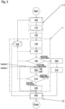
- FIG. 3 The sequence of inspection method 1 is now outlined.
- a borescope with a system according to the invention is required.
- the system has a computer unit and a corresponding test head for the borescope.
- the test head enables the intended non-destructive testing methods to be used.
- the database 105 can be part of the computer unit and thus represent a storage medium of the computer unit.
- preparatory measures 1.1 are carried out, which enable the inspection procedure 1 to be applied repeatedly.
- the preparatory measures are carried out at least once in order to be able to carry out the inspection procedure 1 as often as required.
- the preparatory measures create a data set consisting at least of reference values and preferably also of reference value-related tolerances or tolerance fields, which can also be supplemented by calibration results from test procedures.
- a database 105 is created with reference values of at least the component sections 18 of the component 2 in which the test areas 22, 24, 26, 28 are defined and which are to be examined in the context of the inspection procedure using a borescope with regard to a Changes in their physical material properties are to be investigated.
- the reference values are obtained from reference components that have been in operation and/or are in operation and contain an aging of the component material that results, for example, from temperature events from flight operations such as temperature profile and maximum temperature, running time, operating point of the engine, ETM data and the like.
- Each reference value is assigned a tolerance field in order to be able to determine whether a deviation between the reference value and a measured actual value of the component or component material in the respective test area 22 is tolerable or not tolerable.
- step 110 calibration of test methods
- possible non-destructive test methods are then calibrated on the reference component.
- Exemplary and non-exhaustive test methods are measurements of electrical, magnetic and/or thermal conductivity (eddy current, microwave and thermography), vibration and resonance investigations, penetration properties (X-rays and ultrasound), a conductivity measurement, in particular a conductivity measurement, and the like.
- the results of the calibration can also be written into the database 105.
- the preparatory measures 1.1 for the actual inspection method 1 are thus completed.
- a warning message 120 is generated by a corresponding sensor on the aircraft engine, such as an overtemperature
- the inspection method 1 proposes the steps explained below according to the invention.
- step 130 applying a test method with the device closed
- a non-destructive test method is selected and a borescope is provided with a corresponding test head.
- the system suggests a preferred test method to a user. Criteria for the automated selection can be component material, component accessibility and/or previous component history.
- step 140 compare between actual value and reference value
- a comparison is then made between the actual physical value recorded by the non-destructive testing method and an associated physical reference value of the component area 22, which is read from the database and, as mentioned above, contains the aging of the component 2 or its material in at least this test area 22.
- the comparison is preferably carried out automatically so that the greatest possible objectivity is ensured.
- step 150 evaluation of a deviation
- the evaluation is preferably carried out automatically so that the greatest possible objectivity is ensured.
- the aircraft engine is dismantled from the respective aircraft in a step 300 (opening the device) and the component 2 is destructively examined using materialography in a step 310 (materialography examination). This means that a conventional inspection of the aircraft engine is carried out as explained above.
- test area 22 is preferably subjected to a control test in a step 200 (control test with closed device) to increase safety and reliability (variant 1).
- step 400 writing results to database
- step 400 can be proceeded to directly after the positive evaluation (variant 2).
- Step 400 writing results to database is explained below.
- steps 130 application of a test procedure with the device closed
- 140 comparison between actual value and reference value
- steps 130 application of a test procedure with the device closed
- 140 comparison between actual value and reference value
- the test procedure for the control test is preferably selected automatically based on criteria such as component material, component accessibility and/or previous component history, supplemented by the criterion that the second test procedure is different from the first test procedure.
- step 210 evaluation of a deviation
- step 150 evaluation of a deviation
- step 300 opening the device
- step 310 materialography examination
- step 220 component "OK"
- the component material in the test area 22 is Overtemperature warning has not been damaged to such an extent that the component should not be used any further. Inspection procedure 1 is then completed for test area 22.
- step 400 writing test results to database 105
- step 400 the actual values obtained from the non-destructive tests and also from any necessary materialographic examinations are entered into database 105 for further consideration of aging with regard to test area 22.
- the inspection method 1 provides for the condition of the inaccessible component section 20 to be assessed as "OK" if the control test 200 (steps 130, 140 and 210) also shows that the deviation for an accessible test area, in the example test area 22, is within the permissible tolerance field.
- the inspection method 1 is preferably not only carried out for one test area 22, but the inspection method 1 is, as in Figure 2 indicated, applied to a large number of test areas 22, 24, 26, 28.
- the inspection procedure 1 can be carried out for each test area 22, 24, 26, 28 in isolation from the other test areas 22, 24, 26, 28 or combined.
- Isolated means that the first test procedure and then the control test 200 are carried out on each test area 22, 24, 26, 28 if the deviation of the first test in the front test area 22 was tolerable. Only then does the middle test area 24, then the rear test area 26 and then the suction-side test area 28 come into play.
- Combined means that the first test procedure is first carried out on all test areas 22, 24, 26, 28 and then, provided there is no deviation outside the respective tolerance field, the control test 200 is carried out on the test areas 22, 24, 26, 28.
- the advantage of the isolated approach is that the borescope does not need to be moved or repositioned in any test area for the initial test and for the control test. This ensures that the control test is carried out on exactly the same test area 22, 24, 26, 28 as the previous or initial test, which increases the reliability of the measurement results.
- test head does not have to be changed as often, since the test head is only changed once the initial test has been carried out on all test areas 22, 24, 26, 28.
- borescope and in particular its test head must be calibrated twice on each test area.
- a borescope-based inspection method for checking a condition of a component of a device that is not visible from the outside, wherein a structural change in the component material is detected on the basis of a physical property and evaluated in relation to at least one physical reference value in which aging of the material is taken into account, as well as a system with a computer unit and at least one test head for carrying out such an inspection method for computer-aided and in particular computer-operated selection of a non-destructive testing method for detecting the physical property and the detection of the physical property itself, carrying out a value comparison between a detected actual value and the reference value and an evaluation of a tolerance between the actual value and the reference value.
- FIG. 4a and 4b An exemplary test head 31 of a system 30 according to the invention is shown.
- the exemplary test head 31 is particularly suitable for on-wing inspections of engines. This is, as in Figure 1 shown, is connected to a computer unit 32 via a data line 33.
- the test head 31 can be guided in the folded state, for example, via borescope openings to thermally highly stressed areas such as the leading edge or the middle of the gas channel of turbine blades.
- Its flexible, pincer-shaped design with several links 36 allows opening and optimal enclosing of the area of a component 2 to be tested, such as the leading edge of an airfoil, even with different geometries.
- a main sensor 37 is arranged in the middle, for example for testing the leading edge of an airfoil, which can also be adapted and/or exchanged for different engine types or components 2 such as high-pressure turbine blades if required.
- the side links 36 serve to stabilize and fix the test head 31 to the component 2.
- These can also contain additional sensors in the form of rigid or movable test buttons. 38, for example to check areas behind the leading edge (internal structure of the blade) of turbine blades via the pressure and suction side.
- the movable and exchangeable test head 31 is arranged on a flexible, rigid or stiffenable test head guide 34 with integrated signal and/or control lines 33, which connect the test head 31 to the computer unit 32.
- a pivotable connection device 35 can be provided, on which cameras 39 can be provided for guiding and positioning the test head 31, for carrying out measurements and for documenting the examination.
Landscapes
- Physics & Mathematics (AREA)
- General Physics & Mathematics (AREA)
- Chemical & Material Sciences (AREA)
- Engineering & Computer Science (AREA)
- Health & Medical Sciences (AREA)
- Life Sciences & Earth Sciences (AREA)
- Analytical Chemistry (AREA)
- Biochemistry (AREA)
- General Health & Medical Sciences (AREA)
- Immunology (AREA)
- Pathology (AREA)
- Mechanical Engineering (AREA)
- General Engineering & Computer Science (AREA)
- Combustion & Propulsion (AREA)
- Electrochemistry (AREA)
- Chemical Kinetics & Catalysis (AREA)
- Acoustics & Sound (AREA)
- Electromagnetism (AREA)
- Optics & Photonics (AREA)
- Astronomy & Astrophysics (AREA)
- Signal Processing (AREA)
- Investigating Or Analyzing Materials By The Use Of Magnetic Means (AREA)
- Testing Of Devices, Machine Parts, Or Other Structures Thereof (AREA)
- Investigating Materials By The Use Of Optical Means Adapted For Particular Applications (AREA)
Description
- Die vorliegende Erfindung betrifft ein On-Wing-Inspektionsverfahren nach dem Oberbegriff des Patentanspruchs 1 sowie ein System zur Durchführung eines derartigen Inspektionsverfahrens.
- Vorrichtungen wie Kraftmaschinen, beispielsweise Strömungsmaschinen, sind gewöhnlich zur Zustandsüberwachung von nicht sichtbaren Maschinenbauteilen im Maschineninnern mit einer Vielzahl von Sensoren wie Temperatursensoren und Schwingungssensoren versehen. Registriert nun beispielsweise ein hochdruckturbinenseitiger Temperatursensor eine sogenannte Übertemperatur, so wird bei Flugtriebwerken im Cockpit eine entsprechende Warnmeldung ausgegeben. Zur Überprüfung, ob das Flugtriebwerk durch die Übertemperatur einen Schaden genommen hat, wird das Triebwerk vom Flügel demontiert und auf Bauteilebene zerlegt. An der ersten Hochdruckturbinenstufe wird dann eine zerstörende metallografische Gefügeanalyse durchgeführt. Anhand von Schliffstandards wird die Gefügeänderung der Hochdruckturbinenlaufschaufel an drei Stellen bewertet. Zur Berücksichtigung normaler, alterungsbedingter Effekte auf die Gefügestruktur wird ein Schliff auch aus nicht überhitzten Bereichen der Prüfschaufel, zum Beispiel dem Schaufelfuß, zur Bewertung der Veränderungen in Blattmitte herangezogen. Wird eine unzulässige Schädigung des Bauteils nachgewiesen, sind alle Laufschaufeln dieser Stufe zu ersetzen und die Inspektion wird für eine nachfolgende Turbinenstufe fortgesetzt. Es hat sich jedoch gezeigt, dass in ca. 80 % der Fälle keine Schädigung des Laufschaufelwerkstoffes durch die Übertemperatur eingetreten ist.
- Bislang sind verschiedene Verfahren zur Prüfung des Zustands von außerhalb einer Vorrichtung nicht sichtbaren Bauteilen mittels unterschiedlicher, insbesondere für die jeweiligen Zwecke angepasster Prüfköpfe bekannt, welche teilweise Signalverarbeitungseinrichtungen und Prüfköpfe in verschiedenen Ausbildungen zur Durchführung unterschiedlicher Inspektionsverfahren aufweisen. Solche Verfahren bzw. Aspekte solcher Verfahren und Vorrichtungen hierzu sind beispielsweise in den Dokumenten
US 2012/158319 A1 ,DE 10 2006 048791 A1 ,DE 11 2014 000505 T5 ,US 4 139 822 A ,US 2017/006201 A1 ,JP H07 270261 A US 5 301 061 A ,US 2004/051525 A1 ,US 20143/060289 A1 ,US 2015/192499 A1 ,DE 10 2016 224 049 A1 beschrieben. - Darüber hinaus ist aus dem Dokument
US 2017/241286 A1 ein Verfahren zum Feststellen eines Verzugs in einer Komponente eines Gasturbinenmotors, ausEP 3 171 166 A1 ein Verfahren zum Überprüfen einer von außen nicht sichtbarer Komponente einer Vorrichtung und ausUS 2014/260755 A1 sind mehrgliedrige Roboterarme für Luftanwendungen bekannt, wobei der Roboterarm für die in-situ-Reparatur einer internen Komponente eines Gasturbinentriebwerks verwendet werden kann. - Aufgabe der Erfindung ist es, ein On-Wing-Inspektionsverfahren zu schaffen, dass einen reduzierten Inspektionsaufwand aufweist. Des Weiteren ist es Aufgabe der Erfindung ein System zu schaffen, dass die Durchführung des On-Wing-Inspektionsverfahrens ermöglicht.
- Diese Aufgabe wird gelöst durch ein On-Wing-Inspektionsverfahren mit den Merkmalen des Patentanspruchs 1 und durch ein System mit den Merkmalen des Patentanspruchs 10.
- Ein erfindungsgemäßes On-Wing-Inspektionsverfahren zum Überprüfen eines Zustandes eines von außen nicht sichtbaren Bauteils und insbesondere von außen nicht zugänglichen Bauteils bzw. Bauteilbereichs einer Vorrichtung sieht die Verwendung eines Boroskops vor. In einem 1. Schritt wird ein zerstörungsfreies Prüfverfahren angewendet, bei dem eine physikalische Eigenschaft zumindest eines Bauteilbereichs erfasst wird. In einem Folgeschritt wird ein Vergleich zwischen einem durch das zerstörungsfreie Prüfverfahren erfassten physikalischen Ist-Wert und einem physikalischen Referenzwert des Bauteilbereichs durchgeführt. Der Referenzwert wird aus einer Datenbank gelesen und berücksichtigt eine Alterung des Bauteils. In einem weiteren Schritt wird dann eine Abweichung des Ist-Wertes von dem Referenzwert bewertet.
- Das erfindungsgemäße On-Wing-Inspektionsverfahren trifft eine zuverlässige und klare Entscheidung darüber, ob eine aufwendig herkömmliche Inspektion wie ein Öffnen der Vorrichtung mit beispielsweise einer zerstörenden metallografischen Werkstoffuntersuchung einzelner Bauteile notwendig ist. Es ist erkannt worden, dass eine Gefügeänderung des Bauteils bzw. des Bauteilwerkstoffes nicht nur mittels einer Metallografieuntersuchung bzw. allgemeiner ausgedrückt mittels einer Materialografieuntersuchung nachweisbar ist, sondern dass sich die Gefügeänderung ebenfalls auch auf physikalische Eigenschaften des Bauteils auswirkt, was durch entsprechende physikalische Messverfahren erfasst werden kann. Der Begriff "Materialografieuntersuchung" umfasst Schliffbilduntersuchungen auch von Bauteilen, die nicht metallischer Natur sind, wie zum Beispiel Bauteile aus Faserverbundkunststoffen. Er umfasst somit den Begriff "Metallografieuntersuchung", der wortsinngemäß nur Untersuchungen an metallischen Bauteilen umfasst. Eine boroskopbasierte zerstörungsfreie Überprüfung der Veränderung einer oder mehrerer physikalischer Eigenschaften ermöglicht eine Untersuchung des Bauteils bei geschlossener Vorrichtung und somit an der montierten Vorrichtung. Eine unnötige Zerlegung der Vorrichtung wird vermieden. Die Berücksichtigung der Alterung gewährleistet ein zuverlässiges Prüfergebnis, da eine Abweichung in der jeweils gemessenen physikalischen Eigenschaft nicht auf ein Neuteil bezogen wird, das eben keine Alterungsspuren aufweist, sondern auf ein gelaufenes Bauteil mit gleicher oder zumindest ähnlicher Historie. Die Alterung des Bauteils bzw. Bauteilwerkstoffs, ergibt sich beispielsweise über Temperaturereignisse aus dem Flugbetrieb wie Temperaturverlauf und Höchsttemperatur, Laufdauer, Betriebspunkt des Triebwerks, ETM-Daten und dergleichen. Hierdurch lässt sich der Inspektionsaufwand wesentlich reduzieren. Der Vergleich und die Bewertung erfolgen vorzugsweise automatisiert, so dass eine das Inspektionsverfahren durchführende Person lediglich das Boroskop mit einem Prüfkopf auszuwählen und entsprechend zu positionieren hat. Die Wahl des geeigneten Prüfverfahrens kann sich an Kriterien wie dem Bauteilwerkstoff, der Bauteilzugänglichkeit und/oder der bisherigen Historie des Bauteils orientieren und unter Berücksichtigung dieser beispielhaften Kriterien ebenfalls automatisiert dem Anwender vorgeschlagen werden. Beispielhafte Vorrichtungen sind Kraftmaschinen wie Strömungsmaschinen, insbesondere Flugtriebwerke, Industrieturbinen, Kraftwerksturbinen und Schiffsturbinen.
- Der Inspektionsaufwand wird bei Anwendung des erfindungsgemäßen Inspektionsverfahrens deutlich reduziert. Das Inspektionsverfahren ermöglicht bei einer schnellen Überprüfung mehrerer Schaufeln ein zuverlässigeres Prüfergebnis und somit eine belastbare Ausage über den Zustand des jeweiligen Bauteils. Bei Flugtriebwerken werden unnötige "Shop Visits" vermieden, stattdessen werden die "On-Wing-Zeiten" erhöht.
- Bevorzugte zerstörungsfreie Prüfverfahren beinhalten eine Aussetzung des zumindest einen Bauteilbereichs einem Mikrowellenfeld, einem Ultraschallfeld, Röntgenstrahlen oder einem Wirbelstrom. Weitere alternative oder ergänzende zerstörungsfreie Prüfverfahren sind, ohne einschränkend zu wirken, eine Thermografieanalyse, eine Schwingungs- und Resonanzanalyse und/ oder eine Leitfähigkeitsmessung, insbesondere eine elektrische Leitfähigkeitsmessung.
- So ist zur Durchführung einer Röntgenprüfung die Zugänglichkeit des bzw. der Bauteile von zwei Seiten vorteilhaft. Beispielsweise können durch vorhandene Bohrungen, wie insbesondere bei Strömungsmaschinen Bohrungen in der Brennkammer, die beispielsweise für Einspritzdüsen genutzt werden, der Röntgenstrahler geführt und durch vorhandene Boroskopöffnungen im Gehäuse der Strömungsmaschine Röntgendetektoren eingeführt und sicher positioniert werden.
- Bei der Durchführung einer Wirbelstromprüfung ist es beispielsweise zweckmäßig, den Messkopf bauteilbezogen zu positionieren, um das erfasste Materialvolumen reproduzierbar zu definieren. Hierbei ist die Orientierung und Fixierung des Prüfkopfs insbesondere an den Kühlluftbohrungen verwendbar.
- Eine weitere konkret durchführbare Messmethode ist die prozesskompensierte Resonanzprüfung PCRT (Process Compensated Resonance Testing). Über diese Resonanzanalyse können mittels einer speziellen Hochfrequenzmesstechnik und einer speziellen Analyse-Software auch vergleichsweise kleine lokale Veränderungen im Bauteil erfasst werden.
- Bei der Durchführung einer elektrischen Leitfähigkeitsmessung können die Elektroden zum Festlegen des Strompfads durch das Bauteil so gestaltet werden, dass ein Stromein- und -austritt beispielsweise über die Kühlluftbohrungen erfolgt. Insbesondere ist beim Verwenden von mehr als zwei Messstellen eine Kreuzmessung möglich, die Aussagen um eine Fläche ermöglicht.
- Die genannten Beispiele für zerstörungsfreie Prüfverfahren: Röntgenprüfung Wirbelstromprüfung Resonanzprüfung und Leitfähigkeitsmessung stellen beispielsweise konkrete Anwendungen an Turbinenschaufeln im eingebauten Zustand bei Strömungsmaschinen dar.
- Sollte beim Bewerten festgestellt werden, dass, die Abweichung innerhalb eines zulässigen Toleranzfeldes liegt, sieht ein Ausführungsbeispiel vor, das Bauteil als "in Ordnung" beurteilt wird. Die Inspektionsprüfung kann dann beendet oder zur Erhöhung der Sicherheit und Zuverlässigkeit des Prüfergebnisses für einen weiteren Bauteilbereich oder für ein weiteres Bauteil wiederholt werden.
- Sollte beim Bewerten festgestellt werden, dass die Abweichung außerhalb eines zulässigen Toleranzfeldes liegt, wird das Bauteil bevorzugterweise einer zerstöremden Materialografieuntersuchung unterzogen. Alternativ kann eine erneute zerstörungsfreie Prüfung mit einem alternativen Prüfverfahren durchgeführt werden. Zeigt als Ergebnis auch das zweite Prüfverfahren eine zu große bzw. nicht tolerierbare Abweichung des gemessenen Ist-Wertes von dem Referenzwert, wird das Bauteil erst dann einer zerstörenden Materialografieuntersuchung zugeführt. Sollte jedoch die zweite Prüfung eine tolerierbare Abweichung zeigen, kann eine dritte Prüfung mit einem zum ersten und zweiten Prüfverfahren andersartigen zerstörungsfreien Prüfverfahren durchgeführt werden. Wenn die dritte Prüfung dann eine nicht tolerierbare Abweichung zeigt, wird das Bauteil erst dann einer zerstörenden Materialografieuntersuchung zugeführt. Wenn die dritte Prüfung jedoch eine tolerierbare Abweichung zeigt, kann das Bauteil als "in Ordnung" bewertet werden. Durch diese Maßnahmen kann eine unnötige zerstörende Materialografieuntersuchung verhindert werden.
- Sollte beim Bewerten festgestellt werden, dass, die Abweichung innerhalb eines zulässigen Toleranzfeldes liegt, sieht ein Ausführungsbeispiel vor, die vorgenannten Schritte (Anwendung zerstörungsfreies Prüfverfahren, Wertevergleich und Bewertung) zumindest einmal mit einem andersartigen zerstörungsfreien Prüfverfahren für den zuvor geprüften zumindest einen Bauteilbereich zu wiederholen. Hierdurch wird die Sicherheit, die Zuverlässigkeit und die Objektivität des Inspektionsverfahrens erhöht. Die Auswahl des Prüfverfahrens für die sogenannte Kontrollprüfung erfolgt wie schon die Erstprüfung bevorzugterweise automatisiert anhand von Kriterien wie Bauteilwerkstoff, Bauteilzugänglichkeit und/oder bisherige Bauteilhistorie, ergänzt um das Kriterium, dass das zweite Prüfverfahren andersartig als das erste Prüfverfahren ist. Dabei kann es vorteilhaft sein, wenn zusätzlich das Kriterium mitberücksichtigt werden, dass nicht zwei gleichartige Prüfverfahren verwendet werden. Wenn zum Beispiel das erste Prüfverfahren ein Erfassen der elektrischen Leitfähigkeit zum Gegenstand hatte, so kann es vorteilhaft sein, wenn beim zweiten Prüfverfahren beispielsweise eine Durchleuchtungsprüfung erfolgt. Der Vergleich erfolgt vorzugsweise automatisiert.
- Sollte nach dem erneuten Durchführen der vorgenannten Schritte (Anwendung zerstörungsfreies Prüfverfahren, Wertevergleich und Bewertung) bei der Bewertung festgestellt werden, dass die Abweichung innerhalb eines zulässigen Toleranzfeldes liegt, sieht ein Ausführungsbeispiel vor, dass das Bauteil als "in Ordnung" beurteilt wird. Die Bewertung erfolgt vorzugsweise automatisiert.
- Sollte nach dem erneuten Durchführen der vorgenannten Schritte (Anwendung zerstörungsfreies Prüfverfahren, Wertevergleich und Bewertung) bei der Bewertung festgestellt werden, dass die Abweichung außerhalb eines zulässigen Toleranzfeldes liegt, sieht ein Ausführungsbeispiel vor, dass die Vorrichtung geöffnet und das Bauteil einer zerstörenden Materialografieuntersuchung unterzogen wird. Durch die negativ ausgefallene Kontrollprüfung ist das Bauteil mit großer Wahrscheinlichkeit schadhaft, so dass es wahrscheinlich auszutauschen ist.
- Um eine Aussage über den Zustand eines für einen Prüfkopf des Boroskops unzugänglichen Bauteilbereich zu treffen, sieht ein Ausführungsbeispiel vor, den unzugänglichen Bauteilbereich dann als "in Ordnung" zu bewerten, wenn nach dem erneuten Durchführen der Schritte a) bis c) die Bewertung ein Feststellen umfasst, dass die Abweichung innerhalb eines zulässigen Toleranzfeldes liegt.
- Bevorzugterweise werden die zerstörungsfreien Prüfverfahren, die angewendet werden sollen, zuvor an Referenzbauteilen kalibriert. Die Kalibrierung ist eine vorbereitende Maßnahme und erhöht die Zuverlässigkeit des eigentlichen Inspektionsverfahrens. Die Referenbauteile weisen beispielsweise unterschiedliche Laufzeiten, verschiedene maximale Betriebstemperaturen und dergleichen auf.
- Ein erfindungsgemäßes System, das dazu eingerichtet ist, ein erfindungsgemäßes On-Wing-Inspektionsverfahren durchzuführen, hat eine Rechnereinheit und einen Prüfkopf. Es ist insbesondere zur automatisierten Auswahl des zerstörungsfreien Prüfverfahrens, zur Erfassung der physikalischen Eigenschaft an sich, zur automatisierten Durchführung des Wertevergleichs zwischen dem erfassten Ist-Wert und dem Referenzwert und der automatisierten Bewertung einer Toleranz zwischen dem Ist-Wert und dem Referenzwert eingerichtet. Das System erlaubt eine zuverlässige Zustandsüberprüfung eines im Inneren einer Vorrichtung und von außen nicht sichtbaren und insbesondere von außen nicht zugänglichen Bauteils bzw. Bauteilbereichs. Das System ist mobil und bevorzugterweise von einer das Inspektionsverfahren durchführenden Person tragbar, so dass es schnell an den jeweiligen Einsatzort gebracht werden kann.
- Das System mit Rechnereinheit und Prüfkopf, das zur Durchführung von On-Wing Inspektionen von Triebwerken eingerichtet ist, weist eine insbesondere zangenförmige Ausführung mit mehreren Gliedern auf, wobei mittig am Prüfkopf ein Hauptsensor angeordnet ist. So kann der Prüfkopf beispielsweise zusammenklappbar ausgebildet sein, um im zusammengeklappten Zustand beispielsweise über Boroskopöffnungen an thermisch hoch belastete Stellen beispielsweise bei Turbinenschaufeln wie der Leading Edge, oder die Gaskanalmitte geführt zu werden. Eine flexible, zangenförmige Ausführung mit mehreren Gliedern erlaubt ein Öffnen und ein optimales Umschließen des zu prüfenden Bereiches eines Bauteils wie beispielsweise der Leading Edge eines Airfoils auch bei unterschiedlicher Geometrie. Der mittig angeordnete ein Hauptsensor kann bei Bedarf auch für unterschiedliche Triebwerkstypen bzw. Bauteile wie Hochdruckturbinenschaufeln angepasst und/ oder ausgetauscht werden. Die seitlichen Glieder dienen der Stabilisierung und Fixierung des Prüfkopfes am Bauteil.
- Bei einer Ausführung des Prüfkopfs weisen die seitlichen Glieder zusätzliche Sensoren in Form von starr oder beweglich ausgeführten Prüfknöpfen auf, um bei Turbinenschaufeln beispielsweise Bereiche hinter der Leading Edge (Innenstruktur der Schaufel) über die Druck- und Saugseite zu prüfen.
- Bei einer Ausführung des Prüfkopfs ist der Prüfkopf beweglich und austauschbar ausgeführt, insbesondere zum Durchführen mehrerer Prüfverfahren und zum Anpassens des Systems an verschiedene Prüfaufgaben.
- Bei einer Ausführung ist der Prüfkopf an einer flexiblen, starren oder versteifbaren Prüfkopfführung mit integrierten Signal- und/ oder Steuerleitungen angeordnet ist, welche den Prüfkopf insbesondere mit der Rechnereinheit verbinden, und bei einer Ausführung des Prüfkopfs ist zur Anbindung des Prüfkopfs an die Prüfkopfführung eine schwenkbare Anbindungseinrichtung vorgesehen um eine flexible Bewegbarkeit des Systems bei der Durchführung des Inspektionsverfahrens zu ermöglichen.
- Bei einer Ausführung des Prüfkopfs sind an der Anbindungseinrichtung Kameras vorgesehen, welche insbesondere zur Führung und Positionierung des Prüfkopfes und/ oder zum Durchführen von Messungen und zur Dokumentation der Untersuchung vorgesehen werden kann.
- Sonstige vorteilhafte Ausführungsbeispiele der Erfindung sind Gegenstand weiterer Unteransprüche.
- Im Folgenden werden bevorzugte Ausführungsbeispiele der Erfindung anhand stark vereinfachter schematischer Darstellungen näher erläutert. Es zeigen:
- Figur 1
- eine Seitenansicht eines beispielhaft zu inspizierenden Bauteils,
- Figur 2
- eine Draufsicht auf einen Bereich des in
Figur 1 gezeigten Bauteils, - Figur 3
- einen Ablauf eines erfindungsgemäßen Inspektionsverfahrens, und
- Figur 4a und 4b
- einen beispielhaften Prüfkopf eines erfindungsgemäßen Systems.
- In den
Figuren 1 bis 3 wird ein bevorzugtes Ausführungsbeispiel eines erfindungsgemäßen Inspektionsverfahrens 1 an einem beispielhaften Bauteil 2 erläutert. Das beispielhafte Bauteil 2 ist in denFiguren 1 und 2 skizziert und eine turbinenseitige Laufschaufel 2 einer Strömungsmaschine wie ein Flugtriebwerk. Die Laufschaufel 2 hat im Wesentlichen einen Schaufelfuß 4, ein Schaufelblatt 6 und eine zwischen dem Schaufelfuß 4 und dem Schaufelblatt 6 angeordnete Plattform 8. Das Schaufelblatt 6 hat eine Saugseite 10 sowie eine entgegengesetzte Druckseite 12, die über eine Vorderkante 14 und eine Hinterkante 16 miteinander verbunden sind. - In einem blattseitigen Bauteilabschnitt 18, bevorzugterweise in einem Bauteilabschnitt 18 auf halber Höhe des Schaufelblattes, soll das erfindungsgemäße Inspektionsverfahren 1 beispielhaft angewendet werden. Hierzu wird in dem blattseitigen Bauteilabschnitt 18 ein druckseitiger vorderer Bauteilbereich bzw. Prüfbereich 22 festgelegt. Der Bauteilabschnitt 18 und der Prüfbereich 22 sind nahezu beliebig festlegbar, solange sie für eine folgende zerstörungsfreie boroskopbasierte Prüfung und insbesondere für einen Prüfkopf eines Boroskops zugänglich sind.
- In
Figur 3 ist nun der Ablauf des Inspektionsverfahrens 1 skizziert. Benötigt wird ein Boroskop mit einem erfindungsgemäßen System. Das System weist eine Rechnereinheit und einen entsprechenden Prüfkopf für das Boroskop auf. Der Prüfkopf ermöglicht die Anwendung von den beabsichtigten zerstörungsfreien Prüfverfahren. Die Datenbank 105 kann Teil der Rechnereinheit sein und somit ein Speichermedium der Rechnereinheit darstellen. - Vor dem Beginn des eigentlichen Inspektionsverfahrens 1 werden vorbereitende Maßnahmen 1.1 (Schritte 100 und 110) durchgeführt, die eine wiederholte Anwendung des Inspektionsverfahrens 1 ermöglichen. Die vorbereitenden Maßnahmen werden zumindest einmal vorgenommen, um das Inspektionsverfahren 1 dann beliebig oft durchführen zu können. Im Wesentlichen wird bei den vorbereitenden Maßnahmen eine Datenmenge, zumindest bestehend aus Referenzwerten und bevorzugterweise auch aus referenzwertbezogenen Toleranzen bzw. Toleranzfeldern, angelegt, die zusätzlich um Kalibrierungsergebnisse von Prüfverfahren ergänzt werden können.
- Im Schritt 100 (Erstellen einer Datenbank) wird eine Datenbank 105 mit Referenzwerten von zumindest den Bauteilabschnitten 18 des Bauteils 2 erstellt, in denen die Prüfbereiche 22, 24, 26, 28 definiert sind und die im Rahmen des Inspektionsverfahrens per Boroskop hinsichtlich einer Veränderung ihrer physikalischen Werkstoffeigenschaften untersucht werden sollen. Die Referenzwerte werden von im Betrieb gewesenen und/oder sich im Betrieb befindenden Referenzbauteilen gewonnen und enthalten eine Alterung des Bauteilwerkstoffs, die sich beispielsweise über Temperaturereignisse aus dem Flugbetrieb wie Temperaturverlauf und Höchsttemperatur, Laufdauer, Betriebspunkt des Triebwerks, ETM-Daten und dergleichen ergibt. Jedem Referenzwert wird ein Toleranzfeld zugeordnet, um bestimmen zu können, ob eine Abweichung zwischen dem Referenzwert und einem gemessenen Ist-Wert des Bauteils bzw. Bauteilwerkstoffs im jeweiligen Prüfbereich 22 tolerierbar oder nicht tolerierbar ist.
- Im Schritt 110 (Kalibrieren von Prüfverfahren) werden dann mögliche zerstörungsfreie Prüfverfahren an dem Referenzbauteil kalibriert. Beispielhafte und nicht abschließende Prüfverfahren sind Messungen der elektrischen, magnetischen und/oder thermischen Leitfähigkeit (Wirbelstrom, Mikrowelle und Thermografie), Schwingungs- und Resonanzuntersuchungen, Durchdringungseigenschaften (Röntgenstrahlen und Ultraschall), eine Leitfähigkeitsmessung, insbesondere eine Leitfähigkeitsmessung, und dergleichen. Die Ergebnisse der Kalibrierung können ebenfalls in die Datenbank 105 geschrieben werden.
- Die vorbereitenden Maßnahmen 1.1 für das eigentliche Inspektionsverfahren 1 sind damit abgeschlossen. Sobald nun eine Warnmeldung 120 von einem entsprechenden Sensor an dem Flugtriebwerk wie eine Übertemperatur erzeugt wird, schlägt das Inspektionsverfahren 1 erfindungsgemäß die im Folgenden erläuterten Schritte vor.
- Im Schritt 130 (Anwenden eines Prüfverfahrens bei geschlossener Vorrichtung) wird ein zerstörungsfreies Prüfverfahren ausgewählt und ein Boroskop mit einem entsprechenden Prüfkopf versehen. Bevorzugterweise werden einem Anwender von dem System ein bevorzugtes Prüfverfahren vorgeschlagen. Kriterien für die automatisierte Auswahl können sein Bauteilwerkstoff, Bauteilzugänglichkeit und/oder bisherige Bauteilhistorie.
- Im Schritt 140 (Vergleich zwischen Ist-Wert und Referenzwert) wird dann ein Vergleich zwischen dem durch das zerstörungsfreie Prüfverfahren erfassten physikalischen Ist-Wert und einem zugehörigen physikalischen Referenzwert des Bauteilbereich 22, der aus der Datenbank gelesen wird und wie vorgenannt die Alterung des Bauteils 2 bzw. dessen Werkstoffs in zumindest diesem Prüfbereich 22 enthält, durchgeführt. Der Vergleich erfolgt bevorzugterweise automatisiert, so dass eine größtmögliche Objektivität gegeben ist.
- Im Schritt 150 (Bewertung einer Abweichung) wird dann festgestellt, ob die Abweichung außerhalb oder innerhalb des zulässigen referenzwertbezogenen Toleranzfeldes liegt. Die Bewertung erfolgt vorzugsweise automatisiert, so dass eine größtmögliche Objektivität gegeben ist.
- Wenn die Abweichung außerhalb des Toleranzfeldes liegt, wird in einem Schritt 300 (Öffnen der Vorrichtung) das Flugtriebwerk von dem jeweiligen Fluggerät demontiert und in einem Schritt 310 (Materialografieuntersuchung) das Bauteil 2 zerstörend materialografisch untersucht. D. h., es erfolgt eine eingangs erläuterte herkömmliche Inspektion des Flugtriebwerks.
- Wenn die Abweichung innerhalb des Toleranzfeldes liegt, wird bevorzugterweise zur Erhöhung der Sicherheit und Zuverlässigkeit in einem Schritt 200 (Kontrollprüfung bei geschlossener Vorrichtung) der Prüfbereich 22 einer Kontrollprüfung unterzogen (Variante 1). Alternativ kann direkt nach der positiven Bewertung zum Schritt 400 (Ergebnisse in Datenbank schreiben) gegangen werden (Variante 2). Der Schritt 400 (Ergebnisse in Datenbank schreiben) wird im Folgenden noch erläutert.
- Bei der Kontrollprüfung 200 (Variante 1) werden die Schritte 130 (Anwenden eines Prüfverfahrens bei geschlossener Vorrichtung) und 140 (Vergleich zwischen Ist-Wert und Referenzwert) unter Anwendung eines zum ersten Prüfverfahren andersartigen zerstörungsfreien Prüfverfahrens erneut durchgeführt. Die Auswahl des Prüfverfahrens für die Kontrollprüfung erfolgt wie schon die Erstprüfung bevorzugterweise automatisiert anhand von Kriterien wie Bauteilwerkstoff, Bauteilzugänglichkeit und/oder bisherige Bauteilhistorie, ergänzt um das Kriterium, dass das zweite Prüfverfahren andersartig als das erste Prüfverfahren ist.
- Im Schritt 210 (Bewertung einer Abweichung), der dem Schritt 150 (Bewertung einer Abweichung) entspricht, wird dann zum Abschluss der Kontrollprüfung 200 festgestellt, ob die Abweichung außerhalb oder innerhalb des für die Kontrollprüfung geltenden zulässigen Toleranzfeldes liegt.
- Wenn die Abweichung außerhalb des Toleranzfeldes liegt, wird mit den Schritten 300 (Öffnen der Vorrichtung) und dem oben erläuterten Schritt 310 (Materialografieuntersuchung) weiter verfahren.
- Wenn die Abweichung innerhalb des Toleranzfeldes liegt, wird in einem Schritt 220 (Bauteil "in Ordnung") bestimmt, dass der Bauteilwerkstoff im Prüfbereich 22 durch die Übertemperaturwarnung nicht derart beschädigt wurde, dass das Bauteil nicht weiter verwendet werden dürfte. Das Inspektionsverfahren 1 ist dann für den Prüfbereich 22 abgeschlossen.
- Nach der Durchführung des Inspektionsverfahrens 1 folgt eine Nachbereitung 1.2 (Schritt 400). Dabei werden im Schritt 400 (Prüfergebnisse in Datenbank 105 schreiben) die durch die zerstörungsfreien Prüfungen und auch die durch die gegebenenfalls notwendigen Materialografieuntersuchungen gewonnenen Ist-Werte in die Datenbank 105 zur weiteren Berücksichtigung der Alterung bezüglich des Prüfbereiches 22 eingepflegt.
- Um eine Aussage über die Werkstoffbeschaffenheit einer für das Boroskop bzw. dessen Prüfkopf nicht zugänglichen Bauteilabschnitt zu treffen, beispielsweise ein in
Figur 1 mit dem Bezugszeichen 20 bezifferter fußseitiger Bauteilabschnitt, sieht das Inspektionsverfahren 1 vor, den Zustand des nicht zugänglichen Bauteilabschnitt 20 als "in Ordnung" zu bewerten, wenn auch die Kontrollprüfung 200 (Schritte 130, 140 und 210) ergibt, dass sich die Abweichung für einen zugänglichen Prüfbereich, in dem Beispiel Prüfbereich 22, innerhalb des zulässigen Toleranzfeldes befindet. - Um die Zuverlässigkeit des Inspektionsverfahrens 1 zu erhöhen, wird das Inspektionsverfahren 1 bevorzugterweise nicht nur für einen Prüfbereich 22 durchgeführt, sondern das Inspektionsverfahren 1 wird, wie in
Figur 2 angedeutet, auf eine Vielzahl von Prüfbereichen 22, 24, 26, 28 angewendet. Das Inspektionsverfahren 1 kann dabei für jeden Prüfbereich 22, 24, 26, 28 isoliert von den anderen Prüfbereichen 22, 24, 26, 28 durchgeführt werden oder kombiniert. - "Isoliert" bedeutet, dass an jedem Prüfbereich 22, 24, 26, 28 das erste Prüfverfahren und dann die Kontrollprüfung 200 durchgeführt wird, wenn die Abweichung der ersten Prüfung im vorderen Prüfbereich 22 tolerierbar war. Erst danach wird sich dem mittleren Prüfbereich 24, dann dem hinteren Prüfbereich 26 und dann dem saugseitigen Prüfbereich 28 zugewandt.
- "Kombiniert" bedeutet, dass erst an allen Prüfbereichen 22, 24, 26, 28 das erste Prüfverfahren und dann, sofern sich keine Abweichung außerhalb des jeweiligen Toleranzfeldes befindet, die Kontrollprüfung 200 an den Prüfbereichen 22, 24, 26, 28 durchgeführt wird.
- Der Vorteil des isolierten Vorgehens besteht darin, dass das Boroskop bei jedem Prüfbereich für die erste Prüfung und für die Kontrollprüfung im Prinzip nicht bewegt bzw. neu positioniert werden muss. Hierdurch wird sichergestellt, dass die Kontrollprüfung genau am gleichen Prüfbereich 22, 24, 26, 28 wie die vorhergehende bzw. Erstprüfung durchgeführt wird, was die Zuverlässigkeit der Messergebnisse erhöht.
- Der Vorteil des kombinierten Vorgehens besteht darin, dass im Vergleich zum isolierten Vorgehen der Prüfkopf nicht so häufig gewechselt werden muss, da der Prüfkopf erst gewechselt wird, wenn die Erstprüfung an sämtlichen Prüfbereichen 22, 24, 26, 28 durchgeführt ist. Dafür muss das Boroskop und insbesondere dessen Prüfkopf an jedem Prüfbereich zweimal eingemessen werden.
- Offenbart sind ein boroskopbasiertes Inspektionsverfahren zum Überprüfen eines Zustandes eines von außen nicht sichtbaren Bauteils einer Vorrichtung, wobei eine Gefügeänderung des Bauteilwerkstoffs anhand einer physikalischen Eigenschaft erfasst und bezogen auf zumindest einen physikalischen Referenzwert bewertet wird, in denen eine Alterung des Werkstoffs berücksichtigt ist, sowie ein System mit einer Rechnereinheit und zumindest einem Prüfkopf zur Durchführung eines derartigen Inspektionsverfahrens zur rechnergestützten und insbesondere rechnerdurchgeführten Auswahl eines zerstörungsfreien Prüferverfahrens zur Erfassung der physikalischen Eigenschaft sowie der Erfassung der physikalischen Eigenschaft an sich, Durchführung eines Wertevergleichs zwischen einem erfassten Ist-Wertes und dem Referenzwert und einer Bewertung einer Toleranz zwischen dem Ist-Wert und dem Referenzwert.
- In den
Figuren 4a und 4b ist ein beispielhafter Prüfkopf 31 eines erfindungsgemäßen Systems 30 dargestellt. Der beispielhaft dargestellte Prüfkopf 31 ist insbesondere für On-Wing Inspektionen von Triebwerken geeignet. Dieser ist, wie inFigur 1 dargestellt, über eine Datenleitung 33 mit einer Rechnereinheit 32 verbunden. Der Prüfkopf 31 kann im zusammengeklappten Zustand beispielsweise über Boroskopöffnungen an thermisch hoch belastete Stellen wie der Leading Edge, oder die Gaskanalmitte von Turbinenschaufeln geführt werden. Seine flexible, zangenförmige Ausführung mit mehreren Gliedern 36 erlaubt ein Öffnen und ein optimales Umschließen des zu prüfenden Bereiches eines Bauteils 2 wie beispielsweise der Leading-Edge eines Airfoils auch bei unterschiedlicher Geometrie. Mittig ist ein Hauptsensor 37 beispielsweise zum Prüfen der Leading Edge eines Airfolis angeordnet, der bei Bedarf auch für unterschiedliche Triebwerkstypen bzw. Bauteile 2 wie Hochdruckturbinenschaufeln angepasst und/ oder ausgetauscht werden kann. Die seitlichen Glieder 36 dienen der Stabilisierung und Fixierung des Prüfkopfes 31 am Bauteil 2. Diese können aber auch zusätzliche Sensoren in Form von starr oder beweglich ausgeführten Prüfknöpfen 38 aufweisen, um beispielsweise bei Turbinenschaufeln Bereiche hinter der Leading Edge (Innenstruktur der Schaufel) über die Druck- und Saugseite zu prüfen. - Der bewegliche und austauschbare Prüfkopf 31 ist an einer flexiblen, starren oder versteifbaren Prüfkopfführung 34 mit integrierten Signal- und/ oder Steuerleitungen 33 angeordnet, welche den Prüfkopf 31 mit der Rechnereinheit 32 verbinden. Zur Anbindung des Prüfkopfs 31 an die Prüfkopfführung 34 kann eine schwenkbare Anbindungseinrichtung 35 vorgesehen sein, an welcher Kameras 39 zur Führung und Positionierung des Prüfkopfes 31, zum Durchführen von Messungen und zur Dokumentation der Untersuchung vorgesehen werden kann.
-
- 1
- Inspektionsverfahren
- 2
- Bauteil / Schaufel
- 4
- Schaufelfuß
- 6
- Schaufelblatt
- 8
- Plattform
- 10
- Saugseite
- 12
- Druckseite
- 14
- Vorderkante
- 16
- Hinterkante
- 18
- blattseitiger Bauteilabschnitt
- 20
- fußseitiger Bauteilabschnitt
- 22
- vorderer Bauteilbereich / Prüfbereich
- 24
- mittlerer Bauteilbereich / Prüfbereich
- 26
- hinterer Bauteilbereich / Prüfbereich
- 28
- saugseitiger Bauteilbereich / Prüfbereich
- 30
- System
- 31
- Prüfkopf
- 32
- Rechnereinheit
- 33
- Datenleitung
- 34
- Prüfkopfführung
- 35
- Anbindungseinrichtung
- 36
- Glieder
- 37
- Hauptsensor
- 38
- Prüfknopf
- 39
- Kamera
- 100
- Erstellen Datenbank
- 105
- Datenbank
- 110
- Kalibrieren von Prüfverfahren
- 120
- Warnmeldung
- 130
- Anwenden des Prüfverfahrens bei geschlossener Vorrichtung
- 140
- Vergleich zwischen Ist-Wert und Referenzwert
- 150
- Bewerten einer Abweichung
- 300
- Öffnen der Vorrichtung
- 310
- Materialografieuntersuchung
- 200
- Kontrollprüfung bei geschlossener Vorrichtung
- 210
- Bewerten der Abweichung
- 220
- Bauteil "in Ordnung"
- 400
- Ergebnisse in Datenbank schreiben
Claims (16)
- On-Wing-Inspektionsverfahren (1) zum schnellen Überprüfen eines Zustandes von außen nicht sichtbarer Schaufeln eines Flugtriebwerks mit einem Boroskop, mit den Schritten:a. Anwenden eines zerstörungsfreien Prüfverfahrens (130, 200), bei dem eine physikalische Eigenschaft zumindest eines Bauteilbereichs (22, 24, 26, 28) erfasst wird,b. Durchführen eines Vergleichs (140) zwischen einem durch das zerstörungsfreie Prüfverfahren (130, 200) erfassten physikalischen Ist-Wert und einem physikalischen Referenzwert des Bauteilbereichs (22, 24, 26, 28), der aus einer Datenbank (105) gelesen wird und in dem eine Alterung des Bauteils (2) berücksichtigt ist,c. Bewerten (150, 210) einer Abweichung des Ist-Wertes von dem Referenzwert.
- On-Wing-Inspektionsverfahren nach Patentanspruch 1, wobei bei dem Prüfverfahren (130, 200) der Bauteilbereich (22, 24, 26, 28) einem Mikrowellenfeld, einem Ultraschallfeld, Röntgenstrahlen oder einem Wirbelstrom ausgesetzt wird, eine Thermografieanalyse, Schwingungs- und Resonanzanalysen oder eine Leitfähigkeitsmessung durchgeführt wird.
- On-Wing-Inspektionsverfahren nach Patentanspruch 1 oder 2, wobei das Bewerten (150) ein Feststellen umfasst, dass die Abweichung innerhalb eines zulässigen Toleranzfeldes liegt, und wobei das Bauteil (2) als "in Ordnung" beurteilt wird.
- On-Wing-Inspektionsverfahren nach Patentanspruch 1 oder 2, wobei das Bewerten (150) ein Feststellen umfasst, dass die Abweichung außerhalb eines zulässigen Toleranzfeldes liegt, und wobei das Bauteil (2) einer zerstörenden Materialografieuntersuchung unterzogen wird.
- On-Wing-Inspektionsverfahren nach Patentanspruch 1 oder 2, wobei das Bewerten (150) ein Feststellen umfasst, dass die Abweichung innerhalb eines zulässigen Toleranzfeldes liegt, und wobei die Schritte a) bis c) zumindest einmal mit einem andersartigen zerstörungsfreien Prüfverfahren (200) für den zuvor geprüften zumindest einen Bauteilbereich (22, 24, 26, 28) wiederholt werden.
- On-Wing-Inspektionsverfahren nach Patentanspruch 5, wobei nach dem erneuten Durchführen der Schritte a) bis c) das Bewerten (210) ein Feststellen umfasst, dass die Abweichung innerhalb eines zulässigen Toleranzfeldes liegt, und wobei das Bauteil (2) als "in Ordnung" beurteilt wird.
- On-Wing-Inspektionsverfahren nach Patentanspruch 5, wobei nach dem erneuten Durchführen der Schritte a) bis c) die Bewertung (210) ein Feststellen umfasst, dass die Abweichung außerhalb eines zulässigen Toleranzfeldes liegt, und wobei die Vorrichtung geöffnet und das Bauteil (2) einer Materialografieuntersuchung unterzogen wird.
- On-Wing-Inspektionsverfahren nach Patentanspruch 6, wobei nach dem erneuten Durchführen der Schritte a) bis c) die Bewertung (210) ein Feststellen umfasst, dass die Abweichung innerhalb eines zulässigen Toleranzfeldes liegt, und wobei ein für einen Prüfkopf des Boroskops unzugänglicher Bauteilbereich (22, 24, 26, 28) "in Ordnung" ist.
- On-Wing-Inspektionsverfahren nach einem der vorhergehenden Patentansprüche, wobei das jeweilige Prüfverfahren (130, 200) an Referenzbauteilen kalibriert wird.
- System mit Rechnereinheit (32) und Prüfkopf (31), das dazu eingerichtet ist, ein On-Wing-Inspektionsverfahren (1) nach einem der vorhergehenden Patentansprüche durchzuführen.
- System mit Rechnereinheit (32) und Prüfkopf (31) nach Anspruch 10, wobei der Prüfkopf (31) umfassend eine zangenförmige Ausführung mit mehreren Gliedern (36), wobei mittig am Prüfkopf (31) ein Hauptsensor (37) angeordnet ist.
- System mit Rechnereinheit (32) und Prüfkopf (31) nach Anspruch 11, wobei die seitlichen Glieder (36) zusätzliche Sensoren in Form von starr oder beweglich ausgeführten Prüfköpfen (38) aufweisen.
- System mit Rechnereinheit (32) und Prüfkopf (31) nach einem der Ansprüche 10 bis 12, wobei der Prüfkopf (31) beweglich und austauschbar ausgeführt ist.
- System mit Rechnereinheit (32) und Prüfkopf (31) nach einem der Ansprüche 10 bis 13, wobei der Prüfkopf (31) an einer flexiblen, starren oder versteifbaren Prüfkopfführung (34) mit integrierten Signal- und/ oder Steuerleitungen (33) angeordnet ist, welche den Prüfkopf (31) insbesondere mit der Rechnereinheit (32) verbinden.
- System mit Rechnereinheit (32) und Prüfkopf (31) nach Anspruch 14, wobei zur Anbindung des Prüfkopfs (31) an die Prüfkopfführung (34) eine schwenkbare Anbindungseinrichtung (35) vorgesehen ist.
- System mit Rechnereinheit (32) und Prüfkopf (31) nach Anspruch 15, wobei an der Anbindungseinrichtung (35) Kameras (39) vorgesehen sind.
Applications Claiming Priority (2)
| Application Number | Priority Date | Filing Date | Title |
|---|---|---|---|
| DE102018209609.0A DE102018209609A1 (de) | 2018-06-14 | 2018-06-14 | Inspektionsverfahren und System |
| PCT/DE2019/000160 WO2019238152A2 (de) | 2018-06-14 | 2019-06-11 | Inspektionsverfahren und system |
Publications (2)
| Publication Number | Publication Date |
|---|---|
| EP3807498A2 EP3807498A2 (de) | 2021-04-21 |
| EP3807498B1 true EP3807498B1 (de) | 2025-01-15 |
Family
ID=67402776
Family Applications (1)
| Application Number | Title | Priority Date | Filing Date |
|---|---|---|---|
| EP19742675.2A Active EP3807498B1 (de) | 2018-06-14 | 2019-06-11 | Inspektionsverfahren und system |
Country Status (4)
| Country | Link |
|---|---|
| US (1) | US11976997B2 (de) |
| EP (1) | EP3807498B1 (de) |
| DE (1) | DE102018209609A1 (de) |
| WO (1) | WO2019238152A2 (de) |
Families Citing this family (4)
| Publication number | Priority date | Publication date | Assignee | Title |
|---|---|---|---|---|
| DE102019209495A1 (de) * | 2019-06-28 | 2020-12-31 | MTU Aero Engines AG | Verfahren zum Überprüfen einer Schaufel eines Triebwerks und Überprüfungsvorrichtung zum Überprüfen einer Schaufel eines Triebwerks |
| DE102019211104A1 (de) | 2019-07-25 | 2021-01-28 | Siemens Aktiengesellschaft | Verfahren und Vorrichtung zur Detektion von alterungsbedingten Schäden oder Delaminationen an Bauteilen, insbesondere Leistungsmodulen leistungselektronischer Geräte sowie Leistungselektronisches Gerät, insbesondere Umrichter |
| US11846548B2 (en) * | 2021-03-16 | 2023-12-19 | Kidde Technologies, Inc. | Protective sleeves for fire and overheat detection systems for aircraft applications |
| CN113418938B (zh) * | 2021-06-19 | 2023-04-14 | 西北工业大学 | 航空发动机风扇支板雷达吸波材料对比试验装置及方法 |
Citations (3)
| Publication number | Priority date | Publication date | Assignee | Title |
|---|---|---|---|---|
| US20140260755A1 (en) * | 2013-03-14 | 2014-09-18 | Rolls-Royce Plc | Multi-jointed arm assembly |
| EP3171166A1 (de) * | 2015-11-19 | 2017-05-24 | Rolls-Royce plc | Ultraschallprüfvorrichtung mit einem akustischen wellenleiter |
| US20170241286A1 (en) * | 2016-02-24 | 2017-08-24 | General Electric Company | Detectable Datum Markers for Gas Turbine Engine Components for Measuring Distortion |
Family Cites Families (44)
| Publication number | Priority date | Publication date | Assignee | Title |
|---|---|---|---|---|
| US4139822A (en) * | 1977-06-14 | 1979-02-13 | General Electric Company | Eddy current probe for inspecting interiors of gas turbines, said probe having pivotal adjustments and a borescope |
| US5301061A (en) | 1989-07-27 | 1994-04-05 | Olympus Optical Co., Ltd. | Endoscope system |
| JPH07270261A (ja) | 1994-03-31 | 1995-10-20 | Olympus Optical Co Ltd | 3端子構造を有する圧電振動子を用いた圧覚及び触覚センサ |
| US6031566A (en) | 1996-12-27 | 2000-02-29 | Olympus America Inc. | Method and device for providing a multiple source display and a remote visual inspection system specially adapted for use with the device |
| US6643570B2 (en) * | 2000-06-22 | 2003-11-04 | Barry Bangert | Aircraft engine reliability business model |
| US20190168787A1 (en) * | 2002-06-04 | 2019-06-06 | General Electric Company | Inspection system and method |
| US6867586B2 (en) * | 2002-09-17 | 2005-03-15 | Siemens Westinghouse Power Corporation | Eddy current inspection probe for inspecting multiple portions of a turbine blade having different geometric surfaces |
| DE102006048791A1 (de) | 2006-10-12 | 2008-04-17 | Rieth-Hoerst, Stefan, Dr. | Verfahren zur Prüfung der Qualität von Werkstücken oder Maschinenteilen mittels Schallanalyse |
| DE102009028367A1 (de) * | 2009-08-10 | 2011-02-17 | Robert Bosch Gmbh | Verfahren und Vorrichtung zur Dynamik-Diagnose einer Abgas-Sonde |
| WO2012054867A1 (en) | 2010-10-21 | 2012-04-26 | Vibrant Corporation | Utilizing resonance inspection of in-service parts |
| GB2487930A (en) * | 2011-02-09 | 2012-08-15 | Rolls Royce Plc | Inspection of engine components |
| FR2993375B1 (fr) | 2012-07-10 | 2014-07-18 | Snecma | Methode de detection d'une degradation d'une turbomachine par surveillance des performances de ladite turbomachine |
| US9251582B2 (en) * | 2012-12-31 | 2016-02-02 | General Electric Company | Methods and systems for enhanced automated visual inspection of a physical asset |
| US10162796B2 (en) | 2012-12-31 | 2018-12-25 | General Electric Company | Inspection systems and methods |
| US9954908B2 (en) * | 2013-01-22 | 2018-04-24 | General Electric Company | Systems and methods for collaborating in a non-destructive testing system |
| US9217999B2 (en) | 2013-01-22 | 2015-12-22 | General Electric Company | Systems and methods for analyzing data in a non-destructive testing system |
| US9316512B2 (en) * | 2013-06-11 | 2016-04-19 | The Boeing Company | Nondestructive inspection system for difficult to access areas |
| US20150000405A1 (en) * | 2013-06-27 | 2015-01-01 | Honeywell International Inc. | Non-destructive evaluation methods for determining a thickness of a coating layer on a turbine engine component |
| JP6153410B2 (ja) * | 2013-07-30 | 2017-06-28 | オリンパス株式会社 | ブレード検査装置及びブレード検査方法 |
| JP6242105B2 (ja) * | 2013-07-30 | 2017-12-06 | オリンパス株式会社 | ブレード検査装置及びブレード検査方法 |
| JP6180221B2 (ja) * | 2013-08-01 | 2017-08-16 | オリンパス株式会社 | ブレード検査装置 |
| EP2853970B1 (de) * | 2013-09-30 | 2019-03-13 | MTU Aero Engines GmbH | Verfahren zum Durchführen einer Wartung eines Triebwerks |
| FR3015698B1 (fr) | 2013-12-20 | 2022-10-14 | Turbomeca | Endoscope et procede pour son utilisation |
| US10108003B2 (en) | 2014-05-30 | 2018-10-23 | General Electric Company | Systems and methods for providing monitoring state-based selectable buttons to non-destructive testing devices |
| CH711632A2 (de) * | 2015-10-05 | 2017-04-13 | Gen Electric | System und Verfahren zum Detektieren von Defekten in stationären Komponenten von Rotationsmaschinen. |
| DE102016203904A1 (de) | 2016-03-10 | 2017-09-14 | Siemens Aktiengesellschaft | Verfahren zur Durchführung einer Klangprobe und Endoskopvorrichtung |
| EP3239684A1 (de) * | 2016-04-29 | 2017-11-01 | Siemens Aktiengesellschaft | Fehlerdiagnose während eines tests einer turbineneinheit |
| US10807738B2 (en) * | 2016-12-01 | 2020-10-20 | General Electric Company | Maintenance operation analytics |
| DE102016224049A1 (de) | 2016-12-02 | 2018-06-07 | Lufthansa Technik Ag | Verfahren und Einrichtung zur Schadensvermessung eines hohlen Flugzeug- oder Gasturbinen-Bauteils |
| US10775269B2 (en) * | 2017-02-08 | 2020-09-15 | Raytheon Technologies Corporation | Blade health inspection using an excitation actuator and vibration sensor |
| US10400624B2 (en) * | 2017-05-09 | 2019-09-03 | United Technologies Corporation | System and method for planning engine borescope inspections based on FOD probability estimation |
| US10408770B2 (en) * | 2017-08-31 | 2019-09-10 | George Glover | Video borescope device |
| DE102017218426B3 (de) * | 2017-10-16 | 2019-01-17 | Lufthansa Technik Ag | Vorrichtung und Verfahren zur Boroskopinspektion von Strahltriebwerken |
| US11410298B2 (en) * | 2017-12-05 | 2022-08-09 | Raytheon Technologies Corporation | System and method for determining part damage |
| WO2019109241A1 (zh) * | 2017-12-05 | 2019-06-13 | 程琳 | 将内窥检查的数据进行记录的方法和系统 |
| US10878556B2 (en) * | 2018-01-19 | 2020-12-29 | United Technologies Corporation | Interactive semi-automated borescope video analysis and damage assessment system and method of use |
| US11010887B2 (en) * | 2018-09-17 | 2021-05-18 | General Electric Company | Automated distress ranking system |
| US11103964B2 (en) * | 2018-12-06 | 2021-08-31 | General Electric Company | Service apparatus for use with rotary machines |
| DE102019100577B3 (de) * | 2019-01-11 | 2019-12-19 | Bayerische Motoren Werke Aktiengesellschaft | Verfahren zur Überwachung von Sensorsignalen und quantitative Ermittlung des stöchiometrischen Kraftstoff-Luftverhältnisses des gefahrenen Kraftstoffs mittels Injektortest und Katalysatordiagnose in einem Fahrzeug |
| US11186386B2 (en) * | 2019-04-11 | 2021-11-30 | The Boeing Company | Automated aircraft inspection system |
| US10816510B1 (en) * | 2019-04-20 | 2020-10-27 | The Boeing Company | System and method for using eddy current edge effect to measure a gap between two conductive parts |
| US11260477B2 (en) * | 2019-05-02 | 2022-03-01 | MTU Aero Engines AG | Repair tool for turbomachinery and related method |
| US11480068B2 (en) * | 2019-10-15 | 2022-10-25 | General Electric Company | Systems and method of servicing a turbomachine |
| US12595907B2 (en) * | 2019-11-22 | 2026-04-07 | Rtx Corporation | Inspection port for an attritable engine support structure |
-
2018
- 2018-06-14 DE DE102018209609.0A patent/DE102018209609A1/de not_active Withdrawn
-
2019
- 2019-06-11 US US16/972,736 patent/US11976997B2/en active Active
- 2019-06-11 WO PCT/DE2019/000160 patent/WO2019238152A2/de not_active Ceased
- 2019-06-11 EP EP19742675.2A patent/EP3807498B1/de active Active
Patent Citations (3)
| Publication number | Priority date | Publication date | Assignee | Title |
|---|---|---|---|---|
| US20140260755A1 (en) * | 2013-03-14 | 2014-09-18 | Rolls-Royce Plc | Multi-jointed arm assembly |
| EP3171166A1 (de) * | 2015-11-19 | 2017-05-24 | Rolls-Royce plc | Ultraschallprüfvorrichtung mit einem akustischen wellenleiter |
| US20170241286A1 (en) * | 2016-02-24 | 2017-08-24 | General Electric Company | Detectable Datum Markers for Gas Turbine Engine Components for Measuring Distortion |
Also Published As
| Publication number | Publication date |
|---|---|
| DE102018209609A1 (de) | 2019-12-19 |
| WO2019238152A3 (de) | 2020-02-27 |
| US11976997B2 (en) | 2024-05-07 |
| US20210262895A1 (en) | 2021-08-26 |
| WO2019238152A2 (de) | 2019-12-19 |
| EP3807498A2 (de) | 2021-04-21 |
Similar Documents
| Publication | Publication Date | Title |
|---|---|---|
| EP3807498B1 (de) | Inspektionsverfahren und system | |
| EP2761140B1 (de) | Endoskopiesystem und korrespondierendes verfahren zur untersuchung von gasturbinen | |
| DE68901839T2 (de) | Optische kontrolle von mikrobohrungen einer turbinenschaufel. | |
| DE60219111T2 (de) | Verfahren und System zur Diagnose von Turbinenmotoren | |
| DE69724555T2 (de) | Diagnostische Tendenzanalyse für Flugzeugtriebwerke | |
| EP2715322B1 (de) | Verfahren und vorrichtung zur rissprüfung eines flugzeug- oder gasturbinen-bauteils | |
| EP2678654B1 (de) | Verfahren für die funktionsprüfung von turbomaschinen, sowie prüfeinrichtung dafür | |
| DE102019132038A1 (de) | Verfahren und systeme zur überwachung von rotorschaufeln in turbinentriebwerken | |
| CH698630A2 (de) | Defektmodus-Erkennungseinrichtung. | |
| EP4288768B1 (de) | Verfahren zum prüfen eines bauteils einer strömungsmaschine | |
| DE60314955T2 (de) | Verfahren zur Inspektion von Dampfturbinen | |
| DE2854529A1 (de) | Verfahren und vorrichtung zur ultraschallpruefung | |
| EP3956736A1 (de) | Computer-implementiertes verfahren zur bestimmung von defekten eines mittels eines additiven fertigungsprozesses hergestellten objekts | |
| DE102008034162B4 (de) | Verfahren und Vorrichtung zur scannenden Induktionsthermographie mit flexiblem Bewegungspfad | |
| DE3340516A1 (de) | Verfahren und system zur korrektur der netto-schubmessungen in einer flugtriebwerks-pruefzelle | |
| DE102009039224A1 (de) | Verfahren und Vorrichtung zur Erkennung von verstopften Bohrungen in einem Bauteil | |
| EP2853970B1 (de) | Verfahren zum Durchführen einer Wartung eines Triebwerks | |
| EP2924414B1 (de) | Druckmessvorrichtung zur messung dynamischer drücke sowie gasturbinenbrennkammer mit einer druckmessvorrichtung | |
| EP3732371B1 (de) | Verfahren zum kalibrieren von nominalfrequenzen | |
| DE102012206103B3 (de) | Verfahren zum Ermitteln des Schadensausmaßes eines Einschlagschadens auf einer Oberfläche eines Körpers | |
| EP2808667A1 (de) | Verfahren zur Abschätzung von Risslängenfortschritten | |
| DE102008052904B4 (de) | Verfahren zum Ermitteln von mechanischen Eigenschaften einer Beschaufelung | |
| EP3510255B1 (de) | Verfahren zur eindeutigen positionszuordnung und identifizierung einer turbinenschaufel | |
| EP1363248A1 (de) | Verfahren zur Statuserkennung eines mechanisch beanspruchten Bauteils, ein Computersystem auf dem das Verfahren läuft, ein Computerprogramm mit Programmcode-Mitteln und ein Computer-programmprodukt | |
| DE102018211761A1 (de) | Vorrichtung mit einem Untersuchungsmittel zur zerstörungsfreien Untersuchung eines Bauteils und Verfahren zum Untersuchen eines Bauteils |
Legal Events
| Date | Code | Title | Description |
|---|---|---|---|
| STAA | Information on the status of an ep patent application or granted ep patent |
Free format text: STATUS: UNKNOWN |
|
| STAA | Information on the status of an ep patent application or granted ep patent |
Free format text: STATUS: THE INTERNATIONAL PUBLICATION HAS BEEN MADE |
|
| PUAI | Public reference made under article 153(3) epc to a published international application that has entered the european phase |
Free format text: ORIGINAL CODE: 0009012 |
|
| STAA | Information on the status of an ep patent application or granted ep patent |
Free format text: STATUS: REQUEST FOR EXAMINATION WAS MADE |
|
| 17P | Request for examination filed |
Effective date: 20210108 |
|
| AK | Designated contracting states |
Kind code of ref document: A2 Designated state(s): AL AT BE BG CH CY CZ DE DK EE ES FI FR GB GR HR HU IE IS IT LI LT LU LV MC MK MT NL NO PL PT RO RS SE SI SK SM TR |
|
| AX | Request for extension of the european patent |
Extension state: BA ME |
|
| DAV | Request for validation of the european patent (deleted) | ||
| DAX | Request for extension of the european patent (deleted) | ||
| STAA | Information on the status of an ep patent application or granted ep patent |
Free format text: STATUS: EXAMINATION IS IN PROGRESS |
|
| 17Q | First examination report despatched |
Effective date: 20221129 |
|
| GRAP | Despatch of communication of intention to grant a patent |
Free format text: ORIGINAL CODE: EPIDOSNIGR1 |
|
| STAA | Information on the status of an ep patent application or granted ep patent |
Free format text: STATUS: GRANT OF PATENT IS INTENDED |
|
| INTG | Intention to grant announced |
Effective date: 20240911 |
|
| GRAS | Grant fee paid |
Free format text: ORIGINAL CODE: EPIDOSNIGR3 |
|
| GRAA | (expected) grant |
Free format text: ORIGINAL CODE: 0009210 |
|
| STAA | Information on the status of an ep patent application or granted ep patent |
Free format text: STATUS: THE PATENT HAS BEEN GRANTED |
|
| AK | Designated contracting states |
Kind code of ref document: B1 Designated state(s): AL AT BE BG CH CY CZ DE DK EE ES FI FR GB GR HR HU IE IS IT LI LT LU LV MC MK MT NL NO PL PT RO RS SE SI SK SM TR |
|
| REG | Reference to a national code |
Ref country code: CH Ref legal event code: EP Ref country code: GB Ref legal event code: FG4D Free format text: NOT ENGLISH |
|
| REG | Reference to a national code |
Ref country code: DE Ref legal event code: R096 Ref document number: 502019012816 Country of ref document: DE |
|
| REG | Reference to a national code |
Ref country code: IE Ref legal event code: FG4D Free format text: LANGUAGE OF EP DOCUMENT: GERMAN |
|
| REG | Reference to a national code |
Ref country code: NL Ref legal event code: MP Effective date: 20250115 |
|
| PG25 | Lapsed in a contracting state [announced via postgrant information from national office to epo] |
Ref country code: NL Free format text: LAPSE BECAUSE OF FAILURE TO SUBMIT A TRANSLATION OF THE DESCRIPTION OR TO PAY THE FEE WITHIN THE PRESCRIBED TIME-LIMIT Effective date: 20250115 |
|
| PG25 | Lapsed in a contracting state [announced via postgrant information from national office to epo] |
Ref country code: RS Free format text: LAPSE BECAUSE OF FAILURE TO SUBMIT A TRANSLATION OF THE DESCRIPTION OR TO PAY THE FEE WITHIN THE PRESCRIBED TIME-LIMIT Effective date: 20250415 |
|
| PG25 | Lapsed in a contracting state [announced via postgrant information from national office to epo] |
Ref country code: FI Free format text: LAPSE BECAUSE OF FAILURE TO SUBMIT A TRANSLATION OF THE DESCRIPTION OR TO PAY THE FEE WITHIN THE PRESCRIBED TIME-LIMIT Effective date: 20250115 |
|
| PG25 | Lapsed in a contracting state [announced via postgrant information from national office to epo] |
Ref country code: PL Free format text: LAPSE BECAUSE OF FAILURE TO SUBMIT A TRANSLATION OF THE DESCRIPTION OR TO PAY THE FEE WITHIN THE PRESCRIBED TIME-LIMIT Effective date: 20250115 |
|
| PGFP | Annual fee paid to national office [announced via postgrant information from national office to epo] |
Ref country code: DE Payment date: 20250618 Year of fee payment: 7 |
|
| PG25 | Lapsed in a contracting state [announced via postgrant information from national office to epo] |
Ref country code: ES Free format text: LAPSE BECAUSE OF FAILURE TO SUBMIT A TRANSLATION OF THE DESCRIPTION OR TO PAY THE FEE WITHIN THE PRESCRIBED TIME-LIMIT Effective date: 20250115 |
|
| PGFP | Annual fee paid to national office [announced via postgrant information from national office to epo] |
Ref country code: GB Payment date: 20250620 Year of fee payment: 7 |
|
| REG | Reference to a national code |
Ref country code: LT Ref legal event code: MG9D |
|
| PG25 | Lapsed in a contracting state [announced via postgrant information from national office to epo] |
Ref country code: IS Free format text: LAPSE BECAUSE OF FAILURE TO SUBMIT A TRANSLATION OF THE DESCRIPTION OR TO PAY THE FEE WITHIN THE PRESCRIBED TIME-LIMIT Effective date: 20250515 Ref country code: NO Free format text: LAPSE BECAUSE OF FAILURE TO SUBMIT A TRANSLATION OF THE DESCRIPTION OR TO PAY THE FEE WITHIN THE PRESCRIBED TIME-LIMIT Effective date: 20250415 |
|
| PG25 | Lapsed in a contracting state [announced via postgrant information from national office to epo] |
Ref country code: HR Free format text: LAPSE BECAUSE OF FAILURE TO SUBMIT A TRANSLATION OF THE DESCRIPTION OR TO PAY THE FEE WITHIN THE PRESCRIBED TIME-LIMIT Effective date: 20250115 |
|
| PG25 | Lapsed in a contracting state [announced via postgrant information from national office to epo] |
Ref country code: LV Free format text: LAPSE BECAUSE OF FAILURE TO SUBMIT A TRANSLATION OF THE DESCRIPTION OR TO PAY THE FEE WITHIN THE PRESCRIBED TIME-LIMIT Effective date: 20250115 Ref country code: PT Free format text: LAPSE BECAUSE OF FAILURE TO SUBMIT A TRANSLATION OF THE DESCRIPTION OR TO PAY THE FEE WITHIN THE PRESCRIBED TIME-LIMIT Effective date: 20250515 |
|
| PGFP | Annual fee paid to national office [announced via postgrant information from national office to epo] |
Ref country code: FR Payment date: 20250624 Year of fee payment: 7 |
|
| PG25 | Lapsed in a contracting state [announced via postgrant information from national office to epo] |
Ref country code: GR Free format text: LAPSE BECAUSE OF FAILURE TO SUBMIT A TRANSLATION OF THE DESCRIPTION OR TO PAY THE FEE WITHIN THE PRESCRIBED TIME-LIMIT Effective date: 20250416 Ref country code: BG Free format text: LAPSE BECAUSE OF FAILURE TO SUBMIT A TRANSLATION OF THE DESCRIPTION OR TO PAY THE FEE WITHIN THE PRESCRIBED TIME-LIMIT Effective date: 20250115 |
|
| PG25 | Lapsed in a contracting state [announced via postgrant information from national office to epo] |
Ref country code: SE Free format text: LAPSE BECAUSE OF FAILURE TO SUBMIT A TRANSLATION OF THE DESCRIPTION OR TO PAY THE FEE WITHIN THE PRESCRIBED TIME-LIMIT Effective date: 20250115 |
|
| PG25 | Lapsed in a contracting state [announced via postgrant information from national office to epo] |
Ref country code: SM Free format text: LAPSE BECAUSE OF FAILURE TO SUBMIT A TRANSLATION OF THE DESCRIPTION OR TO PAY THE FEE WITHIN THE PRESCRIBED TIME-LIMIT Effective date: 20250115 |
|
| PG25 | Lapsed in a contracting state [announced via postgrant information from national office to epo] |
Ref country code: DK Free format text: LAPSE BECAUSE OF FAILURE TO SUBMIT A TRANSLATION OF THE DESCRIPTION OR TO PAY THE FEE WITHIN THE PRESCRIBED TIME-LIMIT Effective date: 20250115 |
|
| PG25 | Lapsed in a contracting state [announced via postgrant information from national office to epo] |
Ref country code: IT Free format text: LAPSE BECAUSE OF FAILURE TO SUBMIT A TRANSLATION OF THE DESCRIPTION OR TO PAY THE FEE WITHIN THE PRESCRIBED TIME-LIMIT Effective date: 20250115 |
|
| REG | Reference to a national code |
Ref country code: DE Ref legal event code: R097 Ref document number: 502019012816 Country of ref document: DE |
|
| PG25 | Lapsed in a contracting state [announced via postgrant information from national office to epo] |
Ref country code: EE Free format text: LAPSE BECAUSE OF FAILURE TO SUBMIT A TRANSLATION OF THE DESCRIPTION OR TO PAY THE FEE WITHIN THE PRESCRIBED TIME-LIMIT Effective date: 20250115 Ref country code: CZ Free format text: LAPSE BECAUSE OF FAILURE TO SUBMIT A TRANSLATION OF THE DESCRIPTION OR TO PAY THE FEE WITHIN THE PRESCRIBED TIME-LIMIT Effective date: 20250115 |
|
| PG25 | Lapsed in a contracting state [announced via postgrant information from national office to epo] |
Ref country code: RO Free format text: LAPSE BECAUSE OF FAILURE TO SUBMIT A TRANSLATION OF THE DESCRIPTION OR TO PAY THE FEE WITHIN THE PRESCRIBED TIME-LIMIT Effective date: 20250115 |
|
| PG25 | Lapsed in a contracting state [announced via postgrant information from national office to epo] |
Ref country code: SK Free format text: LAPSE BECAUSE OF FAILURE TO SUBMIT A TRANSLATION OF THE DESCRIPTION OR TO PAY THE FEE WITHIN THE PRESCRIBED TIME-LIMIT Effective date: 20250115 |
|
| PLBE | No opposition filed within time limit |
Free format text: ORIGINAL CODE: 0009261 |
|
| STAA | Information on the status of an ep patent application or granted ep patent |
Free format text: STATUS: NO OPPOSITION FILED WITHIN TIME LIMIT |
|
| REG | Reference to a national code |
Ref country code: CH Ref legal event code: L10 Free format text: ST27 STATUS EVENT CODE: U-0-0-L10-L00 (AS PROVIDED BY THE NATIONAL OFFICE) Effective date: 20251126 |
|
| 26N | No opposition filed |
Effective date: 20251016 |
|
| REG | Reference to a national code |
Ref country code: CH Ref legal event code: H13 Free format text: ST27 STATUS EVENT CODE: U-0-0-H10-H13 (AS PROVIDED BY THE NATIONAL OFFICE) Effective date: 20260127 |
|
| PG25 | Lapsed in a contracting state [announced via postgrant information from national office to epo] |
Ref country code: MC Free format text: LAPSE BECAUSE OF FAILURE TO SUBMIT A TRANSLATION OF THE DESCRIPTION OR TO PAY THE FEE WITHIN THE PRESCRIBED TIME-LIMIT Effective date: 20250115 |
|
| PG25 | Lapsed in a contracting state [announced via postgrant information from national office to epo] |
Ref country code: LU Free format text: LAPSE BECAUSE OF NON-PAYMENT OF DUE FEES Effective date: 20250611 |
|
| REG | Reference to a national code |
Ref country code: BE Ref legal event code: MM Effective date: 20250630 |
|
| PG25 | Lapsed in a contracting state [announced via postgrant information from national office to epo] |
Ref country code: IE Free format text: LAPSE BECAUSE OF NON-PAYMENT OF DUE FEES Effective date: 20250611 |
|
| PG25 | Lapsed in a contracting state [announced via postgrant information from national office to epo] |
Ref country code: BE Free format text: LAPSE BECAUSE OF NON-PAYMENT OF DUE FEES Effective date: 20250630 |
|
| PG25 | Lapsed in a contracting state [announced via postgrant information from national office to epo] |
Ref country code: CH Free format text: LAPSE BECAUSE OF NON-PAYMENT OF DUE FEES Effective date: 20250630 |