EP3808468B1 - Verfahren zur befestigung von geteiltem stempel und abkantbremse - Google Patents
Verfahren zur befestigung von geteiltem stempel und abkantbremse Download PDFInfo
- Publication number
- EP3808468B1 EP3808468B1 EP19819067.0A EP19819067A EP3808468B1 EP 3808468 B1 EP3808468 B1 EP 3808468B1 EP 19819067 A EP19819067 A EP 19819067A EP 3808468 B1 EP3808468 B1 EP 3808468B1
- Authority
- EP
- European Patent Office
- Prior art keywords
- tools
- divided tools
- tool
- attachment portions
- divided
- Prior art date
- Legal status (The legal status is an assumption and is not a legal conclusion. Google has not performed a legal analysis and makes no representation as to the accuracy of the status listed.)
- Active
Links
Images

Classifications
-
- B—PERFORMING OPERATIONS; TRANSPORTING
- B21—MECHANICAL METAL-WORKING WITHOUT ESSENTIALLY REMOVING MATERIAL; PUNCHING METAL
- B21D—WORKING OR PROCESSING OF SHEET METAL OR METAL TUBES, RODS OR PROFILES WITHOUT ESSENTIALLY REMOVING MATERIAL; PUNCHING METAL
- B21D5/00—Bending sheet metal along straight lines, e.g. to form simple curves
- B21D5/02—Bending sheet metal along straight lines, e.g. to form simple curves on press brakes without making use of clamping means
- B21D5/0209—Tools therefor
-
- B—PERFORMING OPERATIONS; TRANSPORTING
- B21—MECHANICAL METAL-WORKING WITHOUT ESSENTIALLY REMOVING MATERIAL; PUNCHING METAL
- B21D—WORKING OR PROCESSING OF SHEET METAL OR METAL TUBES, RODS OR PROFILES WITHOUT ESSENTIALLY REMOVING MATERIAL; PUNCHING METAL
- B21D5/00—Bending sheet metal along straight lines, e.g. to form simple curves
- B21D5/02—Bending sheet metal along straight lines, e.g. to form simple curves on press brakes without making use of clamping means
- B21D5/0209—Tools therefor
- B21D5/0254—Tool exchanging
Definitions
- the present disclosure relates to a divided tool attachment method for attaching a plurality of divided tools to tool attachment portions of a press brake using an automatic tool changer (ATC) and to the press brake. More specifically, the present disclosure relates to an attachment method by which it is possible to attach a plurality of divided tools to tool attachment portions of a press brake in a mutually contact (abutting) state without causing minute gaps between divided tools when the divided tools are attached using an ATC, and to the press brake used in the attachment method.
- ATC automatic tool changer
- an upper tool and a lower tool are attached to upper and lower tables. Also, the workpiece is supplied between the upper and lower tools, the workpiece is positioned therebetween, and the upper and lower tools are engaged, thereby folding the workpiece into a V shape.
- attachment/detachment of the upper tool and the lower tool to and from the upper and lower tables and change of the upper tool and the lower tool from the upper and lower tables are performed in accordance with the lengths of folded lines of workpieces. In this case, a plurality of tools corresponding to the bending lengths of workpieces are needed. Thus, there is a problem that storage and management of the tools are burdensome.
- Patent Literatures 1 and 2 disclose an automatic tool changer (ATC) (see Patent Literatures 1 and 2, for example).
- Patent Literature 3 discloses a tool changing device for a press brake, comprising transfer devices with drivable push chains for the transfer of forming tools. The forming tools are individually placed in the press brake based on positional information.
- a servomotor included in the ATC is controlled on the basis of position information of an encoder included in the servomotor to perform position control of the ATC with reference to information regarding to the positions at which the divided tools are to be positioned, length information of the combined divided tools, and the like.
- a minute gap may remain between divided tools, and this may cause a bending scratch, for example, even in a case in which the ATC is precisely positioned at the command position when the ATC is positioned through position control and the operation of causing the divided tools to approach each other is performed.
- One or more embodiments were made in view of the aforementioned problem to retain a plurality of divided tools with no gaps between the divided tools even in a case in which a plurality of divided tools are combined.
- whether or not the divided tools have abutted on each other is detected by detecting the torque of the servomotor for moving the automatic tool changers. It is thus possible to retain the plurality of divided tools with gaps eliminated between the divided tools attached to the tool attachment portions.
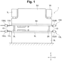
- a press brake 1 includes left and right side frames 3L and 3R.
- An upper table 5U is included above the side frames 3L and 3R.
- a lower table 5L that faces the upper table 5U in an up-down direction (a Z-axis direction) is included below the side frames 3L and 3R.
- the upper table 5U is configured as a ram moved up and down by upper and lower operating devices 7L and 7R such as fluid pressure cylinders, for example, attached to the side frames 3L and 3R.
- Tool attachment portions 9U and 9L in a left-right direction (X-axis direction) to which upper and lower tools (divided tools) P and D are attached are included in the upper and lower tables 5U and 5L.
- guide members 11U and 11L in the left-right direction are included behind the upper and lower tables 5U and 5L (behind the upper and lower tables 5U and 5L in the Y-axis direction).
- Upper and lower automatic tool changers (ATCs) 13U and 13L for changing the tools P and D between tool storage portions (not illustrated in Figure 1 ) and the tool attachment portions 9U and 9L are included in the upper and lower guide members 11U and 11L.
- a pair of left and right ATC 13UL and 13UR and a pair of left and right ATC 13LL and 13LR are included in the upper and lower ATCs 13U and 13L, respectively, so as to be freely movable in the left-right direction along the upper and lower guide members 11U and 11L.
- Each of the ATCs 13UL, 13UR, 13LL, and 13LR can individually move and be positioned in the left-right direction by controlling a servomotor (not illustrated) individually provided for each of the ATCs 13UL, 13UR, 13LL, and 13LR under control of a control device (not illustrated).
- the configuration of the ATCs 13UL, 13UR, 13LL, and 13LR is known as described in WO00/41824 , for example.
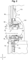
- tool retention members (fingers) 15 that are engageable with engagement holes PH and DH (see Figure 2 ) in the front-back direction included in the tools P and D, respectively, are included in each of the ATCs 13UL, 13UR, 13LL, and 13LR.
- the tool retention members 15 are included to be movable (to be able to advance and retreat) in the front-back direction (the Y-axis direction; the left-right direction in Figure 2 ) in order to engage with the engagement holes PH and DH included in the tools P and D, respectively, or in order to be separated from the engagement holes PH and DH included in the tools P and D, respectively. Therefore, if the tool retention members 15 are retained in an advancing state in which the tool retention members 15 retain the tools P and D and are moved in the left-right direction, then the tool retention members 15 abut on the upper and lower tools P and D attached to the tool attachment portions 9U and 9L in the left-right direction.
- the upper and lower ATCs 13U and 13L are adapted to attach/detach the upper and lower tools P and D to and from the upper and lower tool attachment portions 9U and 9L and change the upper and lower tools P and D from the upper and lower tool attachment portions 9U and 9L, and the tool retention members 15 are included so as to be engageable with the engagement holes PH an DH in the front-back direction included in the upper and lower tools P and D.
- the tool retention members 15 are included so as to be able to advance and retreat with respect to the tools P and D attached to the tool attachment portions 9U and 9L as is well known.
- the tool retention members 15 are retained in a state in which the tool retention members 15 have advanced in a horizontal state when the tool retention members 15 are inserted into the engagement holes PH and DH included in the upper and lower tools P and D, respectively, attached to the tool attachment portions 9U and 9L to hold the tools P and D.
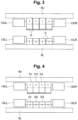
- the attachment is performed as follows. Position control for the upper and lower ATCs 13UL, 13UR, 13LL, and 13LR is performed under control of the control device to arrange the upper and lower tools P and D at desired positions, as conceptually illustrated in Figure 3 . In this case, slight gaps may be generated between the tools P and D as illustrated in Figure 3 due to backlash of the drive unit, deflection of the tool retention members 15, negative drawing tolerance of the tools P and D, and the like.
- tools P1 and D1 on one end side among the tools P and D are positioned at predetermined positions (reference positions) as illustrated in Figure 4 .
- secured states of the tools P1 and D1 are retained in a non-movable state by pressing and securing piece (not illustrated; illustrated with the reference sign 31 in Patent Literature 1) included in the tool attachment portions 9U and 9L or the ATCs 13UL and 13LL on the one side.
- different tools P2, D2, P3, D3, ... are tentatively (temporarily) attached to the tool attachment portions 9U and 9L in a movable state in proximity to the tools P1 and D1 that have already been attached, using the ATCs 13UR and 13LR.
- the tools P2, P3, ..., D2, D3, ... are relatively pressed and moved toward the ATCs 13UL and 13LL using the ATCs 13UR and 13LR.
- a control device 21 that controls the operation of the ATCs 13UR and 13LR pressing the tools P2, P3, ..., D2, D3, ... is configured as follows.
- the control device 21 is configured of a computer, for example, and includes a comparison operation unit 23 as illustrated in Figure 5 .
- a torque detecting unit 27 included in each servomotor 25 for moving the ATCs 13UR and 13LR and the like is connected to the comparison operation unit 23.
- a setting value memory 29 is connected to the comparison operation unit 23.
- the setting value memory 29 stores a torque setting value set in advance.
- a detected torque detected by the torque detecting unit 27 and the torque setting value stored in the setting value memory 29 are compared by the comparison operation unit 23. If the detected torque is equal to the set torque as a result of the comparison, a moving stop command unit 31 connected to the comparison operation unit 23 outputs a stop command signal to the servomotor 25, and the moving of the servomotor 25 is then stopped.
- the pressing by the ATCs 13UR and 13LR is stopped when a pressing force with which the ATCs 13UR and 13LR press the tools P2, P3, ..., D2, D3, ... reaches the setting value set in advance.
- the control device 21 that controls the operations of the press brake 1 includes the setting value memory 29 that stores the torque set in advance and the comparison operation unit 23 that compares a detected torque value with the setting value. Therefore, each of the tools P and D is pressed with a pressing force (torque) set in advance, and the adjacent tools P1, P2, ..., D1, D2, ... abut on (contact with) each other. Thus, no gaps are present between the tools P1, P2, ..., D1, D2, ... as illustrated in Figure 4 .
- the tools P1 and D1 on one end side are positioned at precise positions in advance through positioning control. Then, the tools P2, P3, ..., D2, D3, ... are pressed with a predetermined pressing force set in advance such that the different tools P2, P3, ..., D2, D3, ... that have tentatively been attached are caused to abut on the tools P1 and D1 in a positioned state. Therefore, the adjacent tools P1, P2, ..., D1, D2, ... are arranged in a state in which the adjacent tools P1, P2, ..., D1, D2, ... are in contact with each other. It is thus possible to solve the problem that minute gaps are present between the tools P1, P2, P3, ..., D1, D2, D3, .... Note that when the different tools P2 and D2 are caused to abut on the tools P1 and D1, the tools P1 and D1 are secured in a non-movable state by the ATCs 13UL and 13LL on the one side, for example.
- a plurality of desired tools P2, P3, ..., D2, D3, ... are tentatively attached to the tool attachment portions 9U and 9L using the ATCs 13U and 13L. Then, the plurality of tools P2, P3, ..., D2, D3, ... are collectively moved toward the tools P1 and D1 that have already been attached. Then, the adjacent tools P and D are caused to abut on each other.
- (C) a plurality of desired tools P and D are tentatively attached to the tool attachment portions 9U and 9L using the ATCs 13UR and 13LR. Then, an operation of collectively moving the plurality of tools P and D toward the tools P1 and D1 that have already been attached and causing the tools P and D to abut on each other is repeated a plurality of times. In other words, it is possible to cause the adjacent tools P and D to abut on each other by grouping a plurality of desired tools P and D and pressing the tools P and D in each group toward the tools P1 and D1 every time the tools P and D in each group are attached to the tool attachment portions 9U and 9L using the ATCs 13U and 13L.
Landscapes
- Engineering & Computer Science (AREA)
- Mechanical Engineering (AREA)
- Bending Of Plates, Rods, And Pipes (AREA)
- Mounting, Exchange, And Manufacturing Of Dies (AREA)
Claims (2)
- Verfahren zur Befestigung von geteilten Werkzeugen zum Befestigen mehrerer geteilter Werkzeuge (P, D) an Werkzeugbefestigungsabschnitten (9U, 9L) einer Abkantpresse (1) unter Verwendung erster automatischer Werkzeugwechsler (13UR, 13LR) und zweiter automatischer Werkzeugwechsler (13UL, 13LL), wobei das Verfahren zur Befestigung von geteilten Werkzeugen umfasst:(a) Befestigen verschiedener geteilter Werkzeuge (P, D) an den Werkzeugbefestigungsabschnitten (9U, 9L) in der Nähe von zuvor befestigten geteilten Werkzeugen (P, D) die bereits an den Werkzeugbefestigungsabschnitten (9U, 9L) befestigt sind, unter Verwendung der ersten und zweiten automatischen Werkzeugwechsler (13UR, 13LR, 13UL, 13LL),
charakterisiert durch(b) relatives Bewegen der befestigten verschiedenen geteilten Werkzeuge (P, D) zu den zuvor befestigten geteilten Werkzeugen (P, D) unter Verwendung der ersten automatischen Werkzeugwechsler (13UR, 13LR) und Veranlassen, dass die verschiedenen geteilten Werkzeuge (P, D) an die zuvor befestigten geteilten Werkzeuge (P, D) gepresst werden, die durch die zweiten automatischen Werkzeugwechsler (13UL, 13LL) in einem unbeweglichen Zustand gesichert sind; und(c) Erfassen, dass die verschiedenen geteilten Werkzeuge (P, D) an die zuvor befestigten geteilten Werkzeuge (P, D) angestoßen haben, in einem Fall, in dem ein Drehmoment eines Servomotors (25) zum Bewegen der ersten automatischen Werkzeugwechsler (13UR, 13LR) in einer Links-Rechts-Richtung einen im Voraus eingestellten Einstellwert erreicht hat und Stoppen der Bewegung der verschiedenen geteilten Werkzeuge (P, D). - Abkantpresse (1), umfassend:obere und untere Tische (5U, 5L) mit Werkzeugbefestigungsabschnitten (9U, 9L) zum Befestigen geteilter Werkzeuge (P, D);erste automatische Werkzeugwechsler (13UR, 13LR) und zweite automatische Werkzeugwechsler (13UL, 13LL), die relativ zwischen Werkzeugspeicherabschnitten (17U, 17L) und den Werkzeugbefestigungsabschnitten (9U, 9L) hin und her bewegbar sind, um lösbare geteilte Werkzeuge von den Werkzeugbefestigungsabschnitten (9U, 9L) zu wechseln ( P, D), wobei die ersten und zweiten automatischen Werkzeugwechsler (13UR, 13LR, 13UL, 13LL) konfiguriert sind, um verschiedene geteilte Werkzeuge (P, D) an den Werkzeugbefestigungsabschnitten (9U, 9L) in der Nähe von zuvor befestigten geteilten Werkzeugen (P, D) zu befestigen, die bereits an den Werkzeugbefestigungsabschnitten (9U, 9L) befestigt sind,charakterisiert durcheine Drehmomenterfassungseinheit (27), die so konfiguriert ist, dass sie ein Drehmoment eines Servomotors (25) zum Bewegen der ersten automatischen Werkzeugwechsler (13UR, 13LR) erfasst; undeine Steuervorrichtung (21), die dazu konfiguriert ist:die zweiten automatischen Werkzeugwechsler (13UL, 13LL) zu steuern, um die zuvor angebrachten geteilten Werkzeuge (P, D) in einem nicht beweglichen Zustand zu sichern;die ersten automatischen Werkzeugwechsler (13UR, 13LR) zu steuern, um die verschiedenen geteilten Werkzeuge (P, D) an die zuvor befestigten geteilten Werkzeuge (P, D) zu pressen, indem die befestigten verschiedenen geteilten Werkzeuge (P, D) relativ zu den zuvor angebrachten geteilten Werkzeugen (P, D) bewegt werden;einen im Voraus eingestellten Einstellwert mit einem Erfassungswert, der von der Drehmomenterfassungseinheit (27) erfasst wird, zu vergleichen, wenn die verschiedenen geteilten Werkzeuge (P, D) gegen die zuvor befestigten geteilten Werkzeuge (P, D) gepresst werden; unddie Bewegung der ersten automatischen Werkzeugwechsler (13UR, 13LR) zu stoppen, wenn der Erfassungswert gleich dem Einstellwert ist.
Applications Claiming Priority (2)
| Application Number | Priority Date | Filing Date | Title |
|---|---|---|---|
| JP2018111731A JP6641420B2 (ja) | 2018-06-12 | 2018-06-12 | 分割金型の装着方法及びプレスブレーキ |
| PCT/JP2019/021143 WO2019239883A1 (ja) | 2018-06-12 | 2019-05-28 | 分割金型の装着方法及びプレスブレーキ |
Publications (3)
| Publication Number | Publication Date |
|---|---|
| EP3808468A1 EP3808468A1 (de) | 2021-04-21 |
| EP3808468A4 EP3808468A4 (de) | 2021-08-04 |
| EP3808468B1 true EP3808468B1 (de) | 2023-05-24 |
Family
ID=68843269
Family Applications (1)
| Application Number | Title | Priority Date | Filing Date |
|---|---|---|---|
| EP19819067.0A Active EP3808468B1 (de) | 2018-06-12 | 2019-05-28 | Verfahren zur befestigung von geteiltem stempel und abkantbremse |
Country Status (4)
| Country | Link |
|---|---|
| US (1) | US11794231B2 (de) |
| EP (1) | EP3808468B1 (de) |
| JP (1) | JP6641420B2 (de) |
| WO (1) | WO2019239883A1 (de) |
Families Citing this family (2)
| Publication number | Priority date | Publication date | Assignee | Title |
|---|---|---|---|---|
| JP6789347B2 (ja) * | 2019-05-07 | 2020-11-25 | 株式会社アマダ | 自動金型交換装置及び金型交換方法 |
| US12558717B2 (en) * | 2021-04-21 | 2026-02-24 | Amada Co., Ltd. | Bending system, and divided tool arrangement method |
Family Cites Families (11)
| Publication number | Priority date | Publication date | Assignee | Title |
|---|---|---|---|---|
| JPS63157722A (ja) | 1986-12-19 | 1988-06-30 | Toyo Koki:Kk | 曲げ加工装置 |
| JP2521742B2 (ja) * | 1987-02-20 | 1996-08-07 | 株式会社 アマダ | 折曲げ機 |
| JP2521741B2 (ja) * | 1987-02-20 | 1996-08-07 | 株式会社 アマダ | 折曲げ機 |
| DE3830488A1 (de) * | 1988-09-08 | 1990-03-15 | Fastenrath Fasti Werk | Elektronisches werkzeugerkennungssystem fuer gesenkbiegepressen |
| JP2591415B2 (ja) * | 1992-12-25 | 1997-03-19 | 村田機械株式会社 | 板材折曲機の金型交換装置 |
| JP4558852B2 (ja) | 1998-08-28 | 2010-10-06 | 株式会社アマダ | 金型及び金型交換装置 |
| JP2000094039A (ja) * | 1998-09-18 | 2000-04-04 | Amada Co Ltd | 曲げ加工機 |
| US6240758B1 (en) * | 1999-06-21 | 2001-06-05 | Toyokoki Co., Ltd. | Hydraulic machine |
| EP2613797B1 (de) | 2010-09-09 | 2015-11-04 | University Of Southern California | Zusammensetzungen und verfahren zur brechungsbeseitigung von biofilmen |
| JP5970339B2 (ja) * | 2012-11-01 | 2016-08-17 | 株式会社アマダホールディングス | 金型交換装置 |
| PL2946846T3 (pl) | 2014-05-23 | 2018-02-28 | Felder Kg | Urządzenie do wymiany narzędzi prasy do obróbki plastycznej |
-
2018
- 2018-06-12 JP JP2018111731A patent/JP6641420B2/ja active Active
-
2019
- 2019-05-28 US US16/973,078 patent/US11794231B2/en active Active
- 2019-05-28 WO PCT/JP2019/021143 patent/WO2019239883A1/ja not_active Ceased
- 2019-05-28 EP EP19819067.0A patent/EP3808468B1/de active Active
Also Published As
| Publication number | Publication date |
|---|---|
| US20210245222A1 (en) | 2021-08-12 |
| JP2019214061A (ja) | 2019-12-19 |
| US11794231B2 (en) | 2023-10-24 |
| WO2019239883A1 (ja) | 2019-12-19 |
| EP3808468A1 (de) | 2021-04-21 |
| JP6641420B2 (ja) | 2020-02-05 |
| EP3808468A4 (de) | 2021-08-04 |
Similar Documents
| Publication | Publication Date | Title |
|---|---|---|
| KR101147890B1 (ko) | 공작물용 모듈형 이송 시스템 | |
| US4312110A (en) | Automatic pallet-changing metal-cutting machine | |
| EP2708312B1 (de) | Bearbeitungszentrum | |
| EP4234117B1 (de) | Werkzeugwechselverfahren | |
| CN102056710B (zh) | 用于机床的托盘操纵系统 | |
| US9358601B2 (en) | Method for reshaping a plate-like workpiece | |
| CN104245227B (zh) | 立式加工中心的五面加工用角度头的自动工具交换装置 | |
| KR102319337B1 (ko) | 터릿 공구대 장치 및 이의 공구 교환방법 | |
| EP3808468B1 (de) | Verfahren zur befestigung von geteiltem stempel und abkantbremse | |
| EP4074431B1 (de) | Verfahren zum einlegen einer geteilten form und pressbremse | |
| EP3769884A1 (de) | Hand zum auswechseln einer spannfutterklaue, verfahren zum automatischen auswechseln einer spannfutterklaue und system zum automatischen auswechseln einer klaue | |
| EP3970875B1 (de) | Biegesystem und verfahren zur korrektur von werkzeugfehlausrichtung | |
| FI68545B (fi) | Foerfarande och anordning foer flyttning av ett eller flera fastorgan i ett automatiskt plaotslagericentrum | |
| JP2019122972A (ja) | 金型有無検出方法及びプレスブレーキ | |
| KR20170009060A (ko) | 터닝 센터의 소재 교환 장치 | |
| EP0421580A2 (de) | Werkzeugmaschine mit mehreren Köpfen, vor allem für Holzbearbeitung | |
| CN116619100A (zh) | 一种数控机床换刀装置 | |
| CN108311901B (zh) | 一种自动定位夹具系统及其定位方法 | |
| US12145191B2 (en) | Bending system and tool transport method | |
| JP5252956B2 (ja) | パレット交換可能な工作機械システム | |
| CN210756469U (zh) | 一种工件钻孔夹具 | |
| CN121424143A (zh) | 一种卧式多工位智能加工中心 | |
| JPH05337564A (ja) | パンチプレスにおける金型選択方法とその制御装置 | |
| JPH0780666A (ja) | レーザ複合加工機 |
Legal Events
| Date | Code | Title | Description |
|---|---|---|---|
| STAA | Information on the status of an ep patent application or granted ep patent |
Free format text: STATUS: THE INTERNATIONAL PUBLICATION HAS BEEN MADE |
|
| PUAI | Public reference made under article 153(3) epc to a published international application that has entered the european phase |
Free format text: ORIGINAL CODE: 0009012 |
|
| STAA | Information on the status of an ep patent application or granted ep patent |
Free format text: STATUS: REQUEST FOR EXAMINATION WAS MADE |
|
| 17P | Request for examination filed |
Effective date: 20201217 |
|
| AK | Designated contracting states |
Kind code of ref document: A1 Designated state(s): AL AT BE BG CH CY CZ DE DK EE ES FI FR GB GR HR HU IE IS IT LI LT LU LV MC MK MT NL NO PL PT RO RS SE SI SK SM TR |
|
| AX | Request for extension of the european patent |
Extension state: BA ME |
|
| A4 | Supplementary search report drawn up and despatched |
Effective date: 20210707 |
|
| RIC1 | Information provided on ipc code assigned before grant |
Ipc: B21D 5/02 20060101AFI20210701BHEP Ipc: B21D 37/04 20060101ALI20210701BHEP |
|
| DAV | Request for validation of the european patent (deleted) | ||
| DAX | Request for extension of the european patent (deleted) | ||
| STAA | Information on the status of an ep patent application or granted ep patent |
Free format text: STATUS: EXAMINATION IS IN PROGRESS |
|
| 17Q | First examination report despatched |
Effective date: 20220125 |
|
| RIN1 | Information on inventor provided before grant (corrected) |
Inventor name: NISHIHATA, YUTO Inventor name: ONAGI, YOUSUKE Inventor name: WATANABE, KATSUMI |
|
| INTG | Intention to grant announced |
Effective date: 20230118 |
|
| GRAS | Grant fee paid |
Free format text: ORIGINAL CODE: EPIDOSNIGR3 |
|
| STAA | Information on the status of an ep patent application or granted ep patent |
Free format text: STATUS: GRANT OF PATENT IS INTENDED |
|
| GRAA | (expected) grant |
Free format text: ORIGINAL CODE: 0009210 |
|
| STAA | Information on the status of an ep patent application or granted ep patent |
Free format text: STATUS: THE PATENT HAS BEEN GRANTED |
|
| AK | Designated contracting states |
Kind code of ref document: B1 Designated state(s): AL AT BE BG CH CY CZ DE DK EE ES FI FR GB GR HR HU IE IS IT LI LT LU LV MC MK MT NL NO PL PT RO RS SE SI SK SM TR |
|
| REG | Reference to a national code |
Ref country code: GB Ref legal event code: FG4D |
|
| REG | Reference to a national code |
Ref country code: CH Ref legal event code: EP |
|
| REG | Reference to a national code |
Ref country code: DE Ref legal event code: R096 Ref document number: 602019029351 Country of ref document: DE |
|
| REG | Reference to a national code |
Ref country code: AT Ref legal event code: REF Ref document number: 1569203 Country of ref document: AT Kind code of ref document: T Effective date: 20230615 |
|
| REG | Reference to a national code |
Ref country code: IE Ref legal event code: FG4D |
|
| P01 | Opt-out of the competence of the unified patent court (upc) registered |
Effective date: 20230527 |
|
| REG | Reference to a national code |
Ref country code: LT Ref legal event code: MG9D |
|
| REG | Reference to a national code |
Ref country code: NL Ref legal event code: MP Effective date: 20230524 |
|
| REG | Reference to a national code |
Ref country code: AT Ref legal event code: MK05 Ref document number: 1569203 Country of ref document: AT Kind code of ref document: T Effective date: 20230524 |
|
| PG25 | Lapsed in a contracting state [announced via postgrant information from national office to epo] |
Ref country code: SE Free format text: LAPSE BECAUSE OF FAILURE TO SUBMIT A TRANSLATION OF THE DESCRIPTION OR TO PAY THE FEE WITHIN THE PRESCRIBED TIME-LIMIT Effective date: 20230524 Ref country code: PT Free format text: LAPSE BECAUSE OF FAILURE TO SUBMIT A TRANSLATION OF THE DESCRIPTION OR TO PAY THE FEE WITHIN THE PRESCRIBED TIME-LIMIT Effective date: 20230925 Ref country code: NO Free format text: LAPSE BECAUSE OF FAILURE TO SUBMIT A TRANSLATION OF THE DESCRIPTION OR TO PAY THE FEE WITHIN THE PRESCRIBED TIME-LIMIT Effective date: 20230824 Ref country code: NL Free format text: LAPSE BECAUSE OF FAILURE TO SUBMIT A TRANSLATION OF THE DESCRIPTION OR TO PAY THE FEE WITHIN THE PRESCRIBED TIME-LIMIT Effective date: 20230524 Ref country code: ES Free format text: LAPSE BECAUSE OF FAILURE TO SUBMIT A TRANSLATION OF THE DESCRIPTION OR TO PAY THE FEE WITHIN THE PRESCRIBED TIME-LIMIT Effective date: 20230524 Ref country code: AT Free format text: LAPSE BECAUSE OF FAILURE TO SUBMIT A TRANSLATION OF THE DESCRIPTION OR TO PAY THE FEE WITHIN THE PRESCRIBED TIME-LIMIT Effective date: 20230524 |
|
| PG25 | Lapsed in a contracting state [announced via postgrant information from national office to epo] |
Ref country code: RS Free format text: LAPSE BECAUSE OF FAILURE TO SUBMIT A TRANSLATION OF THE DESCRIPTION OR TO PAY THE FEE WITHIN THE PRESCRIBED TIME-LIMIT Effective date: 20230524 Ref country code: PL Free format text: LAPSE BECAUSE OF FAILURE TO SUBMIT A TRANSLATION OF THE DESCRIPTION OR TO PAY THE FEE WITHIN THE PRESCRIBED TIME-LIMIT Effective date: 20230524 Ref country code: LV Free format text: LAPSE BECAUSE OF FAILURE TO SUBMIT A TRANSLATION OF THE DESCRIPTION OR TO PAY THE FEE WITHIN THE PRESCRIBED TIME-LIMIT Effective date: 20230524 Ref country code: LT Free format text: LAPSE BECAUSE OF FAILURE TO SUBMIT A TRANSLATION OF THE DESCRIPTION OR TO PAY THE FEE WITHIN THE PRESCRIBED TIME-LIMIT Effective date: 20230524 Ref country code: IS Free format text: LAPSE BECAUSE OF FAILURE TO SUBMIT A TRANSLATION OF THE DESCRIPTION OR TO PAY THE FEE WITHIN THE PRESCRIBED TIME-LIMIT Effective date: 20230924 Ref country code: HR Free format text: LAPSE BECAUSE OF FAILURE TO SUBMIT A TRANSLATION OF THE DESCRIPTION OR TO PAY THE FEE WITHIN THE PRESCRIBED TIME-LIMIT Effective date: 20230524 Ref country code: GR Free format text: LAPSE BECAUSE OF FAILURE TO SUBMIT A TRANSLATION OF THE DESCRIPTION OR TO PAY THE FEE WITHIN THE PRESCRIBED TIME-LIMIT Effective date: 20230825 |
|
| PG25 | Lapsed in a contracting state [announced via postgrant information from national office to epo] |
Ref country code: FI Free format text: LAPSE BECAUSE OF FAILURE TO SUBMIT A TRANSLATION OF THE DESCRIPTION OR TO PAY THE FEE WITHIN THE PRESCRIBED TIME-LIMIT Effective date: 20230524 |
|
| REG | Reference to a national code |
Ref country code: CH Ref legal event code: PL |
|
| PG25 | Lapsed in a contracting state [announced via postgrant information from national office to epo] |
Ref country code: SK Free format text: LAPSE BECAUSE OF FAILURE TO SUBMIT A TRANSLATION OF THE DESCRIPTION OR TO PAY THE FEE WITHIN THE PRESCRIBED TIME-LIMIT Effective date: 20230524 |
|
| REG | Reference to a national code |
Ref country code: BE Ref legal event code: MM Effective date: 20230531 |
|
| PG25 | Lapsed in a contracting state [announced via postgrant information from national office to epo] |
Ref country code: SM Free format text: LAPSE BECAUSE OF FAILURE TO SUBMIT A TRANSLATION OF THE DESCRIPTION OR TO PAY THE FEE WITHIN THE PRESCRIBED TIME-LIMIT Effective date: 20230524 Ref country code: SK Free format text: LAPSE BECAUSE OF FAILURE TO SUBMIT A TRANSLATION OF THE DESCRIPTION OR TO PAY THE FEE WITHIN THE PRESCRIBED TIME-LIMIT Effective date: 20230524 Ref country code: RO Free format text: LAPSE BECAUSE OF FAILURE TO SUBMIT A TRANSLATION OF THE DESCRIPTION OR TO PAY THE FEE WITHIN THE PRESCRIBED TIME-LIMIT Effective date: 20230524 Ref country code: LU Free format text: LAPSE BECAUSE OF NON-PAYMENT OF DUE FEES Effective date: 20230528 Ref country code: LI Free format text: LAPSE BECAUSE OF NON-PAYMENT OF DUE FEES Effective date: 20230531 Ref country code: EE Free format text: LAPSE BECAUSE OF FAILURE TO SUBMIT A TRANSLATION OF THE DESCRIPTION OR TO PAY THE FEE WITHIN THE PRESCRIBED TIME-LIMIT Effective date: 20230524 Ref country code: DK Free format text: LAPSE BECAUSE OF FAILURE TO SUBMIT A TRANSLATION OF THE DESCRIPTION OR TO PAY THE FEE WITHIN THE PRESCRIBED TIME-LIMIT Effective date: 20230524 Ref country code: CZ Free format text: LAPSE BECAUSE OF FAILURE TO SUBMIT A TRANSLATION OF THE DESCRIPTION OR TO PAY THE FEE WITHIN THE PRESCRIBED TIME-LIMIT Effective date: 20230524 Ref country code: CH Free format text: LAPSE BECAUSE OF NON-PAYMENT OF DUE FEES Effective date: 20230531 |
|
| REG | Reference to a national code |
Ref country code: DE Ref legal event code: R097 Ref document number: 602019029351 Country of ref document: DE |
|
| PG25 | Lapsed in a contracting state [announced via postgrant information from national office to epo] |
Ref country code: MC Free format text: LAPSE BECAUSE OF FAILURE TO SUBMIT A TRANSLATION OF THE DESCRIPTION OR TO PAY THE FEE WITHIN THE PRESCRIBED TIME-LIMIT Effective date: 20230524 |
|
| REG | Reference to a national code |
Ref country code: IE Ref legal event code: MM4A |
|
| PG25 | Lapsed in a contracting state [announced via postgrant information from national office to epo] |
Ref country code: MC Free format text: LAPSE BECAUSE OF FAILURE TO SUBMIT A TRANSLATION OF THE DESCRIPTION OR TO PAY THE FEE WITHIN THE PRESCRIBED TIME-LIMIT Effective date: 20230524 |
|
| PLBE | No opposition filed within time limit |
Free format text: ORIGINAL CODE: 0009261 |
|
| STAA | Information on the status of an ep patent application or granted ep patent |
Free format text: STATUS: NO OPPOSITION FILED WITHIN TIME LIMIT |
|
| PG25 | Lapsed in a contracting state [announced via postgrant information from national office to epo] |
Ref country code: IE Free format text: LAPSE BECAUSE OF NON-PAYMENT OF DUE FEES Effective date: 20230528 |
|
| GBPC | Gb: european patent ceased through non-payment of renewal fee |
Effective date: 20230824 |
|
| PG25 | Lapsed in a contracting state [announced via postgrant information from national office to epo] |
Ref country code: IE Free format text: LAPSE BECAUSE OF NON-PAYMENT OF DUE FEES Effective date: 20230528 |
|
| 26N | No opposition filed |
Effective date: 20240227 |
|
| PG25 | Lapsed in a contracting state [announced via postgrant information from national office to epo] |
Ref country code: SI Free format text: LAPSE BECAUSE OF FAILURE TO SUBMIT A TRANSLATION OF THE DESCRIPTION OR TO PAY THE FEE WITHIN THE PRESCRIBED TIME-LIMIT Effective date: 20230524 |
|
| PG25 | Lapsed in a contracting state [announced via postgrant information from national office to epo] |
Ref country code: SI Free format text: LAPSE BECAUSE OF FAILURE TO SUBMIT A TRANSLATION OF THE DESCRIPTION OR TO PAY THE FEE WITHIN THE PRESCRIBED TIME-LIMIT Effective date: 20230524 Ref country code: IT Free format text: LAPSE BECAUSE OF FAILURE TO SUBMIT A TRANSLATION OF THE DESCRIPTION OR TO PAY THE FEE WITHIN THE PRESCRIBED TIME-LIMIT Effective date: 20230524 Ref country code: FR Free format text: LAPSE BECAUSE OF NON-PAYMENT OF DUE FEES Effective date: 20230724 Ref country code: BE Free format text: LAPSE BECAUSE OF NON-PAYMENT OF DUE FEES Effective date: 20230531 |
|
| PG25 | Lapsed in a contracting state [announced via postgrant information from national office to epo] |
Ref country code: GB Free format text: LAPSE BECAUSE OF NON-PAYMENT OF DUE FEES Effective date: 20230824 |
|
| PG25 | Lapsed in a contracting state [announced via postgrant information from national office to epo] |
Ref country code: GB Free format text: LAPSE BECAUSE OF NON-PAYMENT OF DUE FEES Effective date: 20230824 |
|
| PG25 | Lapsed in a contracting state [announced via postgrant information from national office to epo] |
Ref country code: BG Free format text: LAPSE BECAUSE OF FAILURE TO SUBMIT A TRANSLATION OF THE DESCRIPTION OR TO PAY THE FEE WITHIN THE PRESCRIBED TIME-LIMIT Effective date: 20230524 |
|
| PG25 | Lapsed in a contracting state [announced via postgrant information from national office to epo] |
Ref country code: BG Free format text: LAPSE BECAUSE OF FAILURE TO SUBMIT A TRANSLATION OF THE DESCRIPTION OR TO PAY THE FEE WITHIN THE PRESCRIBED TIME-LIMIT Effective date: 20230524 |
|
| PGFP | Annual fee paid to national office [announced via postgrant information from national office to epo] |
Ref country code: DE Payment date: 20250521 Year of fee payment: 7 |
|
| PG25 | Lapsed in a contracting state [announced via postgrant information from national office to epo] |
Ref country code: CY Free format text: LAPSE BECAUSE OF FAILURE TO SUBMIT A TRANSLATION OF THE DESCRIPTION OR TO PAY THE FEE WITHIN THE PRESCRIBED TIME-LIMIT; INVALID AB INITIO Effective date: 20190528 |
|
| PG25 | Lapsed in a contracting state [announced via postgrant information from national office to epo] |
Ref country code: HU Free format text: LAPSE BECAUSE OF FAILURE TO SUBMIT A TRANSLATION OF THE DESCRIPTION OR TO PAY THE FEE WITHIN THE PRESCRIBED TIME-LIMIT; INVALID AB INITIO Effective date: 20190528 |
|
| PG25 | Lapsed in a contracting state [announced via postgrant information from national office to epo] |
Ref country code: TR Free format text: LAPSE BECAUSE OF FAILURE TO SUBMIT A TRANSLATION OF THE DESCRIPTION OR TO PAY THE FEE WITHIN THE PRESCRIBED TIME-LIMIT Effective date: 20230524 |