EP3808531A2 - Procédé de conduite d'une buse de vanne à pointeau - Google Patents
Procédé de conduite d'une buse de vanne à pointeau Download PDFInfo
- Publication number
- EP3808531A2 EP3808531A2 EP20202281.0A EP20202281A EP3808531A2 EP 3808531 A2 EP3808531 A2 EP 3808531A2 EP 20202281 A EP20202281 A EP 20202281A EP 3808531 A2 EP3808531 A2 EP 3808531A2
- Authority
- EP
- European Patent Office
- Prior art keywords
- needle
- mold cavity
- nozzle
- shut
- closed position
- Prior art date
- Legal status (The legal status is an assumption and is not a legal conclusion. Google has not performed a legal analysis and makes no representation as to the accuracy of the status listed.)
- Granted
Links
Images

Classifications
-
- B—PERFORMING OPERATIONS; TRANSPORTING
- B29—WORKING OF PLASTICS; WORKING OF SUBSTANCES IN A PLASTIC STATE IN GENERAL
- B29C—SHAPING OR JOINING OF PLASTICS; SHAPING OF MATERIAL IN A PLASTIC STATE, NOT OTHERWISE PROVIDED FOR; AFTER-TREATMENT OF THE SHAPED PRODUCTS, e.g. REPAIRING
- B29C45/00—Injection moulding, i.e. forcing the required volume of moulding material through a nozzle into a closed mould; Apparatus therefor
- B29C45/17—Component parts, details or accessories; Auxiliary operations
- B29C45/26—Moulds
- B29C45/27—Sprue channels ; Runner channels or runner nozzles
- B29C45/28—Closure devices therefor
- B29C45/2806—Closure devices therefor consisting of needle valve systems
-
- B—PERFORMING OPERATIONS; TRANSPORTING
- B29—WORKING OF PLASTICS; WORKING OF SUBSTANCES IN A PLASTIC STATE IN GENERAL
- B29C—SHAPING OR JOINING OF PLASTICS; SHAPING OF MATERIAL IN A PLASTIC STATE, NOT OTHERWISE PROVIDED FOR; AFTER-TREATMENT OF THE SHAPED PRODUCTS, e.g. REPAIRING
- B29C45/00—Injection moulding, i.e. forcing the required volume of moulding material through a nozzle into a closed mould; Apparatus therefor
- B29C45/17—Component parts, details or accessories; Auxiliary operations
- B29C45/26—Moulds
- B29C45/27—Sprue channels ; Runner channels or runner nozzles
- B29C45/2737—Heating or cooling means therefor
-
- B—PERFORMING OPERATIONS; TRANSPORTING
- B29—WORKING OF PLASTICS; WORKING OF SUBSTANCES IN A PLASTIC STATE IN GENERAL
- B29C—SHAPING OR JOINING OF PLASTICS; SHAPING OF MATERIAL IN A PLASTIC STATE, NOT OTHERWISE PROVIDED FOR; AFTER-TREATMENT OF THE SHAPED PRODUCTS, e.g. REPAIRING
- B29C45/00—Injection moulding, i.e. forcing the required volume of moulding material through a nozzle into a closed mould; Apparatus therefor
- B29C45/17—Component parts, details or accessories; Auxiliary operations
- B29C45/76—Measuring, controlling or regulating
- B29C45/7686—Measuring, controlling or regulating the ejected articles, e.g. weight control
-
- B—PERFORMING OPERATIONS; TRANSPORTING
- B29—WORKING OF PLASTICS; WORKING OF SUBSTANCES IN A PLASTIC STATE IN GENERAL
- B29C—SHAPING OR JOINING OF PLASTICS; SHAPING OF MATERIAL IN A PLASTIC STATE, NOT OTHERWISE PROVIDED FOR; AFTER-TREATMENT OF THE SHAPED PRODUCTS, e.g. REPAIRING
- B29C45/00—Injection moulding, i.e. forcing the required volume of moulding material through a nozzle into a closed mould; Apparatus therefor
- B29C45/17—Component parts, details or accessories; Auxiliary operations
- B29C45/76—Measuring, controlling or regulating
- B29C45/77—Measuring, controlling or regulating of velocity or pressure of moulding material
-
- B—PERFORMING OPERATIONS; TRANSPORTING
- B29—WORKING OF PLASTICS; WORKING OF SUBSTANCES IN A PLASTIC STATE IN GENERAL
- B29C—SHAPING OR JOINING OF PLASTICS; SHAPING OF MATERIAL IN A PLASTIC STATE, NOT OTHERWISE PROVIDED FOR; AFTER-TREATMENT OF THE SHAPED PRODUCTS, e.g. REPAIRING
- B29C45/00—Injection moulding, i.e. forcing the required volume of moulding material through a nozzle into a closed mould; Apparatus therefor
- B29C45/17—Component parts, details or accessories; Auxiliary operations
- B29C45/76—Measuring, controlling or regulating
- B29C45/78—Measuring, controlling or regulating of temperature
-
- B—PERFORMING OPERATIONS; TRANSPORTING
- B29—WORKING OF PLASTICS; WORKING OF SUBSTANCES IN A PLASTIC STATE IN GENERAL
- B29C—SHAPING OR JOINING OF PLASTICS; SHAPING OF MATERIAL IN A PLASTIC STATE, NOT OTHERWISE PROVIDED FOR; AFTER-TREATMENT OF THE SHAPED PRODUCTS, e.g. REPAIRING
- B29C45/00—Injection moulding, i.e. forcing the required volume of moulding material through a nozzle into a closed mould; Apparatus therefor
- B29C45/17—Component parts, details or accessories; Auxiliary operations
- B29C45/26—Moulds
- B29C45/27—Sprue channels ; Runner channels or runner nozzles
- B29C45/28—Closure devices therefor
- B29C45/2806—Closure devices therefor consisting of needle valve systems
- B29C2045/2848—Closure devices therefor consisting of needle valve systems having an adjustable stroke length
-
- B—PERFORMING OPERATIONS; TRANSPORTING
- B29—WORKING OF PLASTICS; WORKING OF SUBSTANCES IN A PLASTIC STATE IN GENERAL
- B29C—SHAPING OR JOINING OF PLASTICS; SHAPING OF MATERIAL IN A PLASTIC STATE, NOT OTHERWISE PROVIDED FOR; AFTER-TREATMENT OF THE SHAPED PRODUCTS, e.g. REPAIRING
- B29C45/00—Injection moulding, i.e. forcing the required volume of moulding material through a nozzle into a closed mould; Apparatus therefor
- B29C45/17—Component parts, details or accessories; Auxiliary operations
- B29C45/26—Moulds
- B29C45/27—Sprue channels ; Runner channels or runner nozzles
- B29C45/28—Closure devices therefor
- B29C45/2806—Closure devices therefor consisting of needle valve systems
- B29C2045/2865—Closure devices therefor consisting of needle valve systems having position detecting means
-
- B—PERFORMING OPERATIONS; TRANSPORTING
- B29—WORKING OF PLASTICS; WORKING OF SUBSTANCES IN A PLASTIC STATE IN GENERAL
- B29C—SHAPING OR JOINING OF PLASTICS; SHAPING OF MATERIAL IN A PLASTIC STATE, NOT OTHERWISE PROVIDED FOR; AFTER-TREATMENT OF THE SHAPED PRODUCTS, e.g. REPAIRING
- B29C2945/00—Indexing scheme relating to injection moulding, i.e. forcing the required volume of moulding material through a nozzle into a closed mould
- B29C2945/76—Measuring, controlling or regulating
- B29C2945/76344—Phase or stage of measurement
- B29C2945/76381—Injection
-
- B—PERFORMING OPERATIONS; TRANSPORTING
- B29—WORKING OF PLASTICS; WORKING OF SUBSTANCES IN A PLASTIC STATE IN GENERAL
- B29C—SHAPING OR JOINING OF PLASTICS; SHAPING OF MATERIAL IN A PLASTIC STATE, NOT OTHERWISE PROVIDED FOR; AFTER-TREATMENT OF THE SHAPED PRODUCTS, e.g. REPAIRING
- B29C2945/00—Indexing scheme relating to injection moulding, i.e. forcing the required volume of moulding material through a nozzle into a closed mould
- B29C2945/76—Measuring, controlling or regulating
- B29C2945/76494—Controlled parameter
- B29C2945/76531—Temperature
-
- B—PERFORMING OPERATIONS; TRANSPORTING
- B29—WORKING OF PLASTICS; WORKING OF SUBSTANCES IN A PLASTIC STATE IN GENERAL
- B29C—SHAPING OR JOINING OF PLASTICS; SHAPING OF MATERIAL IN A PLASTIC STATE, NOT OTHERWISE PROVIDED FOR; AFTER-TREATMENT OF THE SHAPED PRODUCTS, e.g. REPAIRING
- B29C2945/00—Indexing scheme relating to injection moulding, i.e. forcing the required volume of moulding material through a nozzle into a closed mould
- B29C2945/76—Measuring, controlling or regulating
- B29C2945/76494—Controlled parameter
- B29C2945/76551—Time
-
- B—PERFORMING OPERATIONS; TRANSPORTING
- B29—WORKING OF PLASTICS; WORKING OF SUBSTANCES IN A PLASTIC STATE IN GENERAL
- B29C—SHAPING OR JOINING OF PLASTICS; SHAPING OF MATERIAL IN A PLASTIC STATE, NOT OTHERWISE PROVIDED FOR; AFTER-TREATMENT OF THE SHAPED PRODUCTS, e.g. REPAIRING
- B29C2945/00—Indexing scheme relating to injection moulding, i.e. forcing the required volume of moulding material through a nozzle into a closed mould
- B29C2945/76—Measuring, controlling or regulating
- B29C2945/76494—Controlled parameter
- B29C2945/76568—Position
-
- B—PERFORMING OPERATIONS; TRANSPORTING
- B29—WORKING OF PLASTICS; WORKING OF SUBSTANCES IN A PLASTIC STATE IN GENERAL
- B29C—SHAPING OR JOINING OF PLASTICS; SHAPING OF MATERIAL IN A PLASTIC STATE, NOT OTHERWISE PROVIDED FOR; AFTER-TREATMENT OF THE SHAPED PRODUCTS, e.g. REPAIRING
- B29C2945/00—Indexing scheme relating to injection moulding, i.e. forcing the required volume of moulding material through a nozzle into a closed mould
- B29C2945/76—Measuring, controlling or regulating
- B29C2945/76494—Controlled parameter
- B29C2945/76595—Velocity
- B29C2945/76598—Velocity linear movement
-
- B—PERFORMING OPERATIONS; TRANSPORTING
- B29—WORKING OF PLASTICS; WORKING OF SUBSTANCES IN A PLASTIC STATE IN GENERAL
- B29C—SHAPING OR JOINING OF PLASTICS; SHAPING OF MATERIAL IN A PLASTIC STATE, NOT OTHERWISE PROVIDED FOR; AFTER-TREATMENT OF THE SHAPED PRODUCTS, e.g. REPAIRING
- B29C2945/00—Indexing scheme relating to injection moulding, i.e. forcing the required volume of moulding material through a nozzle into a closed mould
- B29C2945/76—Measuring, controlling or regulating
- B29C2945/76655—Location of control
- B29C2945/76732—Mould
- B29C2945/76752—Mould runners, nozzles
- B29C2945/76755—Mould runners, nozzles nozzles
-
- B—PERFORMING OPERATIONS; TRANSPORTING
- B29—WORKING OF PLASTICS; WORKING OF SUBSTANCES IN A PLASTIC STATE IN GENERAL
- B29C—SHAPING OR JOINING OF PLASTICS; SHAPING OF MATERIAL IN A PLASTIC STATE, NOT OTHERWISE PROVIDED FOR; AFTER-TREATMENT OF THE SHAPED PRODUCTS, e.g. REPAIRING
- B29C2945/00—Indexing scheme relating to injection moulding, i.e. forcing the required volume of moulding material through a nozzle into a closed mould
- B29C2945/76—Measuring, controlling or regulating
- B29C2945/76822—Phase or stage of control
- B29C2945/76859—Injection
-
- B—PERFORMING OPERATIONS; TRANSPORTING
- B29—WORKING OF PLASTICS; WORKING OF SUBSTANCES IN A PLASTIC STATE IN GENERAL
- B29C—SHAPING OR JOINING OF PLASTICS; SHAPING OF MATERIAL IN A PLASTIC STATE, NOT OTHERWISE PROVIDED FOR; AFTER-TREATMENT OF THE SHAPED PRODUCTS, e.g. REPAIRING
- B29C2945/00—Indexing scheme relating to injection moulding, i.e. forcing the required volume of moulding material through a nozzle into a closed mould
- B29C2945/76—Measuring, controlling or regulating
- B29C2945/76929—Controlling method
- B29C2945/76936—The operating conditions are corrected in the next phase or cycle
-
- B—PERFORMING OPERATIONS; TRANSPORTING
- B29—WORKING OF PLASTICS; WORKING OF SUBSTANCES IN A PLASTIC STATE IN GENERAL
- B29C—SHAPING OR JOINING OF PLASTICS; SHAPING OF MATERIAL IN A PLASTIC STATE, NOT OTHERWISE PROVIDED FOR; AFTER-TREATMENT OF THE SHAPED PRODUCTS, e.g. REPAIRING
- B29C2945/00—Indexing scheme relating to injection moulding, i.e. forcing the required volume of moulding material through a nozzle into a closed mould
- B29C2945/76—Measuring, controlling or regulating
- B29C2945/76929—Controlling method
- B29C2945/76939—Using stored or historical data sets
Definitions
- the invention relates to a method for operating a needle valve nozzle.
- Hot runner nozzles and injection molding tools are well known. They are usually used in the processing of materials, for example thermoplastic materials or liquid silicones, by means of injection molding technology, which are only flowable and thus malleable at a certain minimum temperature. To do this, it is necessary to bring the hot runner nozzle to this minimum temperature - which is dependent on the material to be processed - and to keep it there, which is usually done with the aid of heating devices.
- Hot runner nozzles can be designed as a needle valve nozzle, comprising a valve needle, which passes through the needle valve nozzle in a longitudinally displaceable manner along a stroke and is adjustable by means of a drive between an opening position and a closing position that closes the outlet opening of the nozzle.
- the flowable material is fed to a separable tool block (mold cavity) at a specifiable temperature and under high pressure.
- a separable tool block (mold cavity) at a specifiable temperature and under high pressure.
- These are usually on one temperature-controlled distribution system several - also temperature-controlled - hot runner nozzles mounted, which feed the material to be processed into the mold cavity or the mold cavity in a metered manner via a flow channel. There the material forms a product that corresponds to the mold cavity.
- the quality of the injection-molded product depends, among other things, on whether the filling quantity of the material introduced into the mold cavity is appropriately dimensioned in order to avoid injection molding errors, for example. Injection molding errors due to incorrect metering of the material can be, for example, sink marks, incomplete cavity filling, webbed feet or vacuoles. Other quality criteria can also be used to measure the quality of the injection molded product. In order to meet these quality criteria, a quality-assuring mold cavity filling quantity can first be calculated simulatively or iteratively or empirically determined before the start of production.
- One way of regulating the amount of material that can be introduced into the mold cavity is to control the needle stroke.
- the stroke path or its length and the stroke speed of the valve needle can be adjustable.
- the EP 3 299 140 B1 provides a control of a needle stroke speed in such a way that, depending on the detected system state, a valve pin referred to as a valve pin is moved at different speeds within a stroke.
- this approach requires considerable real-time sensors and corresponding control means, so that this method can be described as complex and time-consuming.
- the WO 2017/144344 A1 discloses, according to its title, a method for carrying out a cyclical production process, the method according to the generally held main claim providing: changing at least one process setting variable; Determine automatically at least one process parameter variant for a changed process setting variable; Automatic checking whether the determined process parameter variant is within a process stability limit and is process stable; Checking whether the quality feature of the goods produced with a changed process setting value lies within the quality tolerance of the goods produced and thus good parts have been produced; and automated creation of a process parameter zone with at least one determined process parameter variant which is process-stable and whose process setting variable produces good parts.
- the method therefore proposes the determination of a process parameter zone which is to be approximated by changing the process setting values by a To prevent the injection molding process from drifting out of a stable state.
- This process can be described as time-consuming, in particular due to the obligatory test for process stability and the extensive test procedure for the formation of the process parameter zone.
- the object of the present invention is therefore to propose a method for operating a needle valve nozzle in an injection molding device, in particular a method for the initial determination of a quality-assuring mold cavity filling quantity, which ensures a predefined quality of an injection-molded product in the simplest possible way.
- the capacity of the cavity is then a desired filling quantity if the at least one predefined quality criterion is met.
- the requirement for a method that is simplified compared to the known prior art excludes the use of complex sensors and, if necessary, real-time sensors that have been used up to now.
- the shut-off needle therefore does not move to an intermediate position or remains there during a single stroke. Rather, the shut-off needle can only be adjusted between the closed and the open position.
- the valve pin does not move at different speeds during a single stroke. Rather, the shut-off needle is adjusted with a travel speed that is constant over the entire stroke of a stroke. Because of the constant adjustment speed, the method according to the invention does not require any sensor system specifically provided for this purpose for detecting valve pin positions.
- the position of the valve needles had to be known at all times in order to be able to change the travel speed of the valve needles accordingly if a criterion was present.
- the invention reduces the previously known method complexity, since the valve pin position monitored by means of sensors no longer has to be processed as information by a control loop.
- the method according to the invention therefore considerably reduces the complexity of known methods in a surprisingly simple manner.
- the method is based on an iterative approximation of desired process parameters that enable a desired product quality.
- at least one process parameter is initially specified as a starting value and a first injection molding process is carried out based on this.
- An injection molding process comprises at least one injection of material into the cavity, possibly pressing down and cooling the material in the cavity, and removing the product formed from the material from the cavity from the mold. Then either the product is compared with at least one previously defined quality criterion or at least one process parameter recorded during the injection is compared with at least one previously defined quality criterion, or both.
- the product can be measured manually or automatically in order to compare it.
- the result can either be that the quality criterion is met or not. If the quality criterion is met, there is a quality criterion-fulfilling and thus desired filling quantity and the method can be ended. If the quality criterion is not met, however, it can be concluded on the basis of the type and / or the numerical size of the non-fulfillment whether the injected mold cavity filling quantity was too large or too small. The Then one or more process parameters (needle stroke path, needle stroke speed, needle stroke acceleration, nozzle temperature and outlet opening duration) are changed accordingly and a subsequent iteration is carried out. This can be done until the desired process parameters for the needle shut-off nozzle have been determined.
- the needle stroke can be changed, for example, in that the open position of the shut-off needle is spatially further removed from the closed position (increase) or is moved closer to the closed position (reduction).
- the needle stroke speed can be changed, for example, by activating the drive accordingly.
- the nozzle temperature can be changed, for example, by means of a control and the outlet opening duration can be changed, for example, in that the loss needle remains in its open position for a longer (increase) or shorter (reduction). Individual process parameters can also influence each other.
- an internal mold cavity pressure and / or a mold cavity wall temperature and / or an optical or mechanical quality feature is recorded as a measured value immediately after the valve needle has been moved into its closed position.
- This measured value can serve as a numerical description of the product or process parameter in order to carry out the comparison in a simple way.
- the recorded measured value is stored in a database.
- This measured value can be used, for example, to determine one or more process parameters in subsequent applications of the method, for example when determining a mold cavity filling quantity for comparable mold cavities, since the result or the effect of a process parameter can be estimated and thus a process parameter can already be specified which presumably is already approximated to the process parameter, which corresponds to a suitable mold cavity filling quantity.
- the process parameters can be stored in a database if the product corresponds to the at least one predefined quality criterion.
- This measured value can be used, for example, as the starting value of the method in the event that a mold cavity filling quantity is to be determined for comparable mold cavities.
- the injection molding device comprises at least one mold cavity and at least one separate needle shut-off nozzle is assigned to each mold cavity, the Process parameters can be specified and specified separately for each needle shut-off nozzle.
- the method according to the invention can namely also advantageously be used with a multiple cavity, that is to say when several cavities are to be filled and several needle shut-off nozzles are to be set.
- the method can then provide that the comparison of the product formed in the mold cavity and / or of at least one process parameter recorded during injection with at least one predefined quality criterion in order to determine whether the mold cavity filling quantity was too large or too small is carried out on a cavity-related basis and that The result from this comparison of the needle shut-off nozzle assigned to the cavity is beneficial in terms of increasing / reducing one or more process parameters.
- valve needle is adjusted by means of a stepper motor or servo motor serving as a drive, which preferably comprises an encoder and / or preferably has a position query means, and / or can preferably be operated pneumatically, hydraulically or electrically.
- the position query means can be designed in such a way that it detects positions of the shut-off needle exclusively in its open and / or closed position, but not in between.
- the method can be designed such that a real-time position of the shut-off needle is not detected by a sensor system.
- the method according to the invention can namely also be carried out in a simple manner without these data.
- a sensor system is to be understood as one which is used exclusively or at least primarily to detect the position of the needle. If this data is generated anyway, for example by an encoder, it is at least not used in the method.
- the current position of the valve needle is namely not necessary for the proposed method.
- the method can provide that the valve needle is not moved into intermediate positions between its open position and its closed position.
- An intermediate position is present, for example, when a travel speed of the valve needle changes from a first speed to a second speed of the opposite changed speed within one stroke.
- the needle position at which the change in speed takes effect should be regarded as an intermediate position.
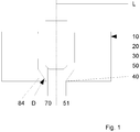
- Valve gate nozzle is part of an injection molding tool (not shown further). It has a nozzle body 20, which is preferably externally heated, in which a (not visible) material pipe is formed which delimits a melt channel 30 concentrically to the longitudinal axis L of the needle valve nozzle 10.
- a melt to be processed for example a metal, silicone or plastic melt, can be fed to a mold cavity (not shown in detail) via the melt channel 30 and an outlet opening 40. The mold cavity is therefore fluidically connected to the needle shut-off nozzle.
- an axially displaceable shut-off needle 50 is provided, which penetrates the melt channel 30 in a longitudinally displaceable manner and can be brought from an open position to a closed position by means of a drive (not shown), an open position being shown.
- the closure needle 50 which is at least partially cylindrical, has a closure part 70 at its end which, in the closed position, engages through an end section 84 of the nozzle body 20 into a cylindrical sealing seat D.
- This is in the exemplary embodiment Fig. 1 Introduced in front of a sprue opening 51 and conical in its upper area so that the closure part 70 - supported by the melt accumulating there - can move into the sealing seat D with little friction.
- the method for operating a valve gate nozzle in an injection molding device can start in step S01, after which at least one process parameter is specified for the valve gate nozzle, selected from the group comprising: needle stroke path, needle stroke speed, needle stroke acceleration, nozzle temperature and outlet opening duration.
- the value of the process parameter can be freely selected or based on empirical values. A value can be selected that realizes a mold cavity filling quantity that is as quality-assuring as possible in order to keep the number of iterations as low as possible.
- the shut-off needle 50 is adjusted from its closed position into its open position in accordance with the at least one process parameter with a continuous needle stroke speed defined before the adjustment.
- shut-off needle 50 is then moved from its open position into its closed position in accordance with the process parameter at a continuous needle stroke speed in S04.
- the cast product and the filling quantity are then evaluated in S05.
- the item manufactured in an injection molding process is considered a product. Therefore, both a single and a multiple cavity produce a product in one injection molding process.
- the product can also be assessed in sections. For this purpose, the product formed in the mold cavity and / or at least one process parameter detected during the injection is compared with at least one predefined quality criterion in order to determine whether the mold cavity filling quantity was too large, too small or suitable. If the product meets one or more quality criteria, the injected quantity is considered suitable and the process can be ended, as S06 shows.
- This at least one value-changed process parameter is defined as a new predetermined process parameter and the method is described above from step S01 Sequence carried out again in order to approximate and achieve the appropriate mold cavity filling quantity.
- This at least one value-modified process parameter is defined as a new predetermined process parameter and the method is carried out again from step S01 in the sequence described above in order to approximate and achieve the suitable mold cavity filling quantity.
- the predefined quality criterion can also be a range of values.
- the comparison shows that the filling quantity was too large or too small and a subsequent comparison in the immediately following iteration results in the opposite of the first comparison, namely that the filling quantity was too small or too large.
- an intermediate value of the process value (s) of the first and second iteration can then be selected for the third iteration, for example.
Landscapes
- Engineering & Computer Science (AREA)
- Manufacturing & Machinery (AREA)
- Mechanical Engineering (AREA)
- Injection Moulding Of Plastics Or The Like (AREA)
- Moulds For Moulding Plastics Or The Like (AREA)
Priority Applications (1)
| Application Number | Priority Date | Filing Date | Title |
|---|---|---|---|
| EP23189458.5A EP4249202A3 (fr) | 2019-10-16 | 2020-10-16 | Procédé de conduite d'une buse de vanne à pointeau |
Applications Claiming Priority (1)
| Application Number | Priority Date | Filing Date | Title |
|---|---|---|---|
| DE102019127988.7A DE102019127988A1 (de) | 2019-10-16 | 2019-10-16 | Verfahren zum Betrieb einer Nadelverschlussdüse |
Related Child Applications (2)
| Application Number | Title | Priority Date | Filing Date |
|---|---|---|---|
| EP23189458.5A Division EP4249202A3 (fr) | 2019-10-16 | 2020-10-16 | Procédé de conduite d'une buse de vanne à pointeau |
| EP23189458.5A Division-Into EP4249202A3 (fr) | 2019-10-16 | 2020-10-16 | Procédé de conduite d'une buse de vanne à pointeau |
Publications (4)
| Publication Number | Publication Date |
|---|---|
| EP3808531A2 true EP3808531A2 (fr) | 2021-04-21 |
| EP3808531A3 EP3808531A3 (fr) | 2021-07-28 |
| EP3808531C0 EP3808531C0 (fr) | 2023-09-13 |
| EP3808531B1 EP3808531B1 (fr) | 2023-09-13 |
Family
ID=73131624
Family Applications (2)
| Application Number | Title | Priority Date | Filing Date |
|---|---|---|---|
| EP20202281.0A Active EP3808531B1 (fr) | 2019-10-16 | 2020-10-16 | Procédé de conduite d'une buse de vanne à pointeau |
| EP23189458.5A Pending EP4249202A3 (fr) | 2019-10-16 | 2020-10-16 | Procédé de conduite d'une buse de vanne à pointeau |
Family Applications After (1)
| Application Number | Title | Priority Date | Filing Date |
|---|---|---|---|
| EP23189458.5A Pending EP4249202A3 (fr) | 2019-10-16 | 2020-10-16 | Procédé de conduite d'une buse de vanne à pointeau |
Country Status (2)
| Country | Link |
|---|---|
| EP (2) | EP3808531B1 (fr) |
| DE (1) | DE102019127988A1 (fr) |
Cited By (1)
| Publication number | Priority date | Publication date | Assignee | Title |
|---|---|---|---|---|
| CN117400502A (zh) * | 2023-10-31 | 2024-01-16 | 山东佳邦机械设备有限公司 | 一种注塑机节能控制系统及控制方法 |
Citations (2)
| Publication number | Priority date | Publication date | Assignee | Title |
|---|---|---|---|---|
| WO2017144344A1 (fr) | 2016-02-22 | 2017-08-31 | Kistler Holding Ag | Procédé de mise en oeuvre d'un processus de production cyclique |
| EP3299140B1 (fr) | 2013-06-24 | 2019-05-01 | Synventive Molding Solutions, Inc. | Appareil et procédé de commande d'écoulement de moulage par injection |
Family Cites Families (8)
| Publication number | Priority date | Publication date | Assignee | Title |
|---|---|---|---|---|
| JPS5215566U (fr) * | 1975-07-22 | 1977-02-03 | ||
| US4279582A (en) * | 1979-04-02 | 1981-07-21 | Incoe Corporation | Method and apparatus for individual control of injection mold shut-off bushings |
| US9440389B2 (en) * | 2011-11-23 | 2016-09-13 | Synventive Molding Solutions, Inc. | Controlled valve pin movement based on cavity sensor feedback |
| WO2014150632A1 (fr) * | 2013-03-18 | 2014-09-25 | Husky Injection Molding Systems Ltd. | Contrôle de matière fondue dans un système de moulage par injection |
| EP2926971B1 (fr) * | 2014-04-03 | 2019-09-11 | Ashley Stone | Dispositifs de canaux chauffants et méthodes comprenant un ensemble actionné par la force de Lorentz |
| US9919462B2 (en) * | 2014-12-10 | 2018-03-20 | Inglass S.P.A. | Molding apparatus and method for producing articles molded through sequential injection |
| DE102016003970A1 (de) * | 2015-04-02 | 2016-10-06 | Otto Männer Innovation GmbH | Heißkanalvorrichtung zum seitlichen Angießen mit kontinuierlicher Ventilnadelbewegung |
| US10875226B2 (en) * | 2016-07-20 | 2020-12-29 | Synventive Molding Soliutions, Inc. | Injection molding apparatus and method for automatic cycle to cycle cavity injection |
-
2019
- 2019-10-16 DE DE102019127988.7A patent/DE102019127988A1/de active Pending
-
2020
- 2020-10-16 EP EP20202281.0A patent/EP3808531B1/fr active Active
- 2020-10-16 EP EP23189458.5A patent/EP4249202A3/fr active Pending
Patent Citations (2)
| Publication number | Priority date | Publication date | Assignee | Title |
|---|---|---|---|---|
| EP3299140B1 (fr) | 2013-06-24 | 2019-05-01 | Synventive Molding Solutions, Inc. | Appareil et procédé de commande d'écoulement de moulage par injection |
| WO2017144344A1 (fr) | 2016-02-22 | 2017-08-31 | Kistler Holding Ag | Procédé de mise en oeuvre d'un processus de production cyclique |
Cited By (1)
| Publication number | Priority date | Publication date | Assignee | Title |
|---|---|---|---|---|
| CN117400502A (zh) * | 2023-10-31 | 2024-01-16 | 山东佳邦机械设备有限公司 | 一种注塑机节能控制系统及控制方法 |
Also Published As
| Publication number | Publication date |
|---|---|
| DE102019127988A1 (de) | 2021-04-22 |
| EP3808531C0 (fr) | 2023-09-13 |
| EP3808531A3 (fr) | 2021-07-28 |
| EP4249202A2 (fr) | 2023-09-27 |
| EP3808531B1 (fr) | 2023-09-13 |
| EP4249202A3 (fr) | 2023-12-27 |
Similar Documents
| Publication | Publication Date | Title |
|---|---|---|
| EP0062788B1 (fr) | Procédé et dispositif pour la fabrication en particulier d'ébauches creuses en matière thermoplastique | |
| EP0909628B1 (fr) | Méthode et dispositif pour le réglage du chauffage du canal d'injection d'un moule à cavités multiples | |
| EP0026828B1 (fr) | Dispositif pour influencer le poids d'un corps creux thermoplastique fabriqué selon le procédé d'extrusion-soufflage | |
| EP2583811B1 (fr) | Procédé de quantification de basculements de procédés dans le cadre d'un processus d'injection d'une machine de moulage par injection | |
| EP0897786B1 (fr) | Procédé de régulation d'une machine de moulage par injection de matières plastiques | |
| EP2360003A1 (fr) | Procédé et dispositif de commande d'une buse d'obturateur à aiguille d'un outil de moulage par injection | |
| DE102018107870A1 (de) | Verfahren, Vorrichtung und Presse zum Spritzgießen von Kunststoff | |
| DE3886461T2 (de) | Verfahren und vorrichtung zum regulieren des einspritzdruckes einer spritzgiessmaschine. | |
| DE69617974T2 (de) | Kombinationssteuerung für das spritzgiessen | |
| EP1377427A1 (fr) | Procede pour la regulation du retrait de pieces moulees par injection | |
| DE102016101523B4 (de) | System und Verfahren zum Spritzgießen von Kunststoffen | |
| EP1056583B1 (fr) | Procede pour evaluer des pieces moulees | |
| EP3698937B1 (fr) | Procédé pour régler le remplissage d'au moins une cavité | |
| EP3808531B1 (fr) | Procédé de conduite d'une buse de vanne à pointeau | |
| DE69212622T2 (de) | Verfahren zur Steuerung einer Spritzgiessmaschine in Abhängigkeit vom Harzdruck in der Düse | |
| DE69015083T2 (de) | Rohkunststoffzufuhranlage für eine Formmaschine. | |
| DE3608973C2 (de) | Verfahren und Vorrichtung zum Steuern des Umschaltens von der Nachdruckphase in die isochore Abkühlphase beim Spritzgießen thermoplastischer Kunststoffe | |
| DE102015121498B4 (de) | Verfahren und Vorrichtung zum Spritzgießen von Kunststoffen | |
| EP0407847B1 (fr) | Procédé et dispositif pour produire des corps creux en matière thermoplastique | |
| DE4221423C2 (de) | Verfahren und Vorrichtung zum Herstellen von Gegenständen aus thermoplastischem Kunststoff durch Spritzgießen | |
| DE102006048788B4 (de) | Verfahren und Vorrichtung zur Herstellung eines einen Hohlraum aufweisenden Bauteils aus Kunststoff | |
| DE10052068A1 (de) | Werkzeug einer Spritzguß- oder Spritzprägemaschine, Verfahren zur Herstellung einer implantierbaren Linse sowie implantierbare Linse | |
| DE4336243A1 (de) | Verfahren zum Spritzgießen von Kunststoffkörpern und Vorrichtung zur Durchführung des Verfahrens | |
| WO2025172560A1 (fr) | Procédé de détermination d'au moins un paramètre pendant un processus de moulage par injection et dispositif de moulage par injection | |
| DE102011105765A1 (de) | Vorrichtung und Verfahren zum Spritzgießen von Kunststoff-Formteilen aus thermoplastischem Kunststoff |
Legal Events
| Date | Code | Title | Description |
|---|---|---|---|
| PUAI | Public reference made under article 153(3) epc to a published international application that has entered the european phase |
Free format text: ORIGINAL CODE: 0009012 |
|
| STAA | Information on the status of an ep patent application or granted ep patent |
Free format text: STATUS: THE APPLICATION HAS BEEN PUBLISHED |
|
| AK | Designated contracting states |
Kind code of ref document: A2 Designated state(s): AL AT BE BG CH CY CZ DE DK EE ES FI FR GB GR HR HU IE IS IT LI LT LU LV MC MK MT NL NO PL PT RO RS SE SI SK SM TR |
|
| AX | Request for extension of the european patent |
Extension state: BA ME |
|
| PUAL | Search report despatched |
Free format text: ORIGINAL CODE: 0009013 |
|
| AK | Designated contracting states |
Kind code of ref document: A3 Designated state(s): AL AT BE BG CH CY CZ DE DK EE ES FI FR GB GR HR HU IE IS IT LI LT LU LV MC MK MT NL NO PL PT RO RS SE SI SK SM TR |
|
| RIC1 | Information provided on ipc code assigned before grant |
Ipc: B29C 45/28 20060101AFI20210624BHEP Ipc: B29C 45/76 20060101ALI20210624BHEP Ipc: B29C 45/77 20060101ALI20210624BHEP Ipc: B29C 45/78 20060101ALI20210624BHEP Ipc: B29C 45/27 20060101ALI20210624BHEP |
|
| STAA | Information on the status of an ep patent application or granted ep patent |
Free format text: STATUS: REQUEST FOR EXAMINATION WAS MADE |
|
| 17P | Request for examination filed |
Effective date: 20220128 |
|
| RBV | Designated contracting states (corrected) |
Designated state(s): AL AT BE BG CH CY CZ DE DK EE ES FI FR GB GR HR HU IE IS IT LI LT LU LV MC MK MT NL NO PL PT RO RS SE SI SK SM TR |
|
| GRAP | Despatch of communication of intention to grant a patent |
Free format text: ORIGINAL CODE: EPIDOSNIGR1 |
|
| STAA | Information on the status of an ep patent application or granted ep patent |
Free format text: STATUS: GRANT OF PATENT IS INTENDED |
|
| INTG | Intention to grant announced |
Effective date: 20230405 |
|
| GRAS | Grant fee paid |
Free format text: ORIGINAL CODE: EPIDOSNIGR3 |
|
| GRAA | (expected) grant |
Free format text: ORIGINAL CODE: 0009210 |
|
| STAA | Information on the status of an ep patent application or granted ep patent |
Free format text: STATUS: THE PATENT HAS BEEN GRANTED |
|
| AK | Designated contracting states |
Kind code of ref document: B1 Designated state(s): AL AT BE BG CH CY CZ DE DK EE ES FI FR GB GR HR HU IE IS IT LI LT LU LV MC MK MT NL NO PL PT RO RS SE SI SK SM TR |
|
| REG | Reference to a national code |
Ref country code: CH Ref legal event code: EP |
|
| REG | Reference to a national code |
Ref country code: DE Ref legal event code: R096 Ref document number: 502020005214 Country of ref document: DE |
|
| REG | Reference to a national code |
Ref country code: IE Ref legal event code: FG4D Free format text: LANGUAGE OF EP DOCUMENT: GERMAN |
|
| REG | Reference to a national code |
Ref country code: CH Ref legal event code: PK Free format text: BERICHTIGUNGEN |
|
| U01 | Request for unitary effect filed |
Effective date: 20231011 |
|
| U07 | Unitary effect registered |
Designated state(s): AT BE BG DE DK EE FI FR IT LT LU LV MT NL PT SE SI Effective date: 20231019 |
|
| RIN2 | Information on inventor provided after grant (corrected) |
Inventor name: SOMMER, STEFAN Inventor name: SCHNELL, TORSTEN Inventor name: SOMMER, SIEGRID Inventor name: GUENTHER, HERBERT |
|
| PG25 | Lapsed in a contracting state [announced via postgrant information from national office to epo] |
Ref country code: GR Free format text: LAPSE BECAUSE OF FAILURE TO SUBMIT A TRANSLATION OF THE DESCRIPTION OR TO PAY THE FEE WITHIN THE PRESCRIBED TIME-LIMIT Effective date: 20231214 |
|
| PG25 | Lapsed in a contracting state [announced via postgrant information from national office to epo] |
Ref country code: RS Free format text: LAPSE BECAUSE OF FAILURE TO SUBMIT A TRANSLATION OF THE DESCRIPTION OR TO PAY THE FEE WITHIN THE PRESCRIBED TIME-LIMIT Effective date: 20230913 Ref country code: NO Free format text: LAPSE BECAUSE OF FAILURE TO SUBMIT A TRANSLATION OF THE DESCRIPTION OR TO PAY THE FEE WITHIN THE PRESCRIBED TIME-LIMIT Effective date: 20231213 Ref country code: HR Free format text: LAPSE BECAUSE OF FAILURE TO SUBMIT A TRANSLATION OF THE DESCRIPTION OR TO PAY THE FEE WITHIN THE PRESCRIBED TIME-LIMIT Effective date: 20230913 Ref country code: GR Free format text: LAPSE BECAUSE OF FAILURE TO SUBMIT A TRANSLATION OF THE DESCRIPTION OR TO PAY THE FEE WITHIN THE PRESCRIBED TIME-LIMIT Effective date: 20231214 |
|
| U20 | Renewal fee for the european patent with unitary effect paid |
Year of fee payment: 4 Effective date: 20240116 |
|
| PG25 | Lapsed in a contracting state [announced via postgrant information from national office to epo] |
Ref country code: IS Free format text: LAPSE BECAUSE OF FAILURE TO SUBMIT A TRANSLATION OF THE DESCRIPTION OR TO PAY THE FEE WITHIN THE PRESCRIBED TIME-LIMIT Effective date: 20240113 |
|
| PG25 | Lapsed in a contracting state [announced via postgrant information from national office to epo] |
Ref country code: ES Free format text: LAPSE BECAUSE OF FAILURE TO SUBMIT A TRANSLATION OF THE DESCRIPTION OR TO PAY THE FEE WITHIN THE PRESCRIBED TIME-LIMIT Effective date: 20230913 |
|
| PG25 | Lapsed in a contracting state [announced via postgrant information from national office to epo] |
Ref country code: SM Free format text: LAPSE BECAUSE OF FAILURE TO SUBMIT A TRANSLATION OF THE DESCRIPTION OR TO PAY THE FEE WITHIN THE PRESCRIBED TIME-LIMIT Effective date: 20230913 Ref country code: RO Free format text: LAPSE BECAUSE OF FAILURE TO SUBMIT A TRANSLATION OF THE DESCRIPTION OR TO PAY THE FEE WITHIN THE PRESCRIBED TIME-LIMIT Effective date: 20230913 Ref country code: IS Free format text: LAPSE BECAUSE OF FAILURE TO SUBMIT A TRANSLATION OF THE DESCRIPTION OR TO PAY THE FEE WITHIN THE PRESCRIBED TIME-LIMIT Effective date: 20240113 Ref country code: ES Free format text: LAPSE BECAUSE OF FAILURE TO SUBMIT A TRANSLATION OF THE DESCRIPTION OR TO PAY THE FEE WITHIN THE PRESCRIBED TIME-LIMIT Effective date: 20230913 Ref country code: CZ Free format text: LAPSE BECAUSE OF FAILURE TO SUBMIT A TRANSLATION OF THE DESCRIPTION OR TO PAY THE FEE WITHIN THE PRESCRIBED TIME-LIMIT Effective date: 20230913 Ref country code: SK Free format text: LAPSE BECAUSE OF FAILURE TO SUBMIT A TRANSLATION OF THE DESCRIPTION OR TO PAY THE FEE WITHIN THE PRESCRIBED TIME-LIMIT Effective date: 20230913 |
|
| PG25 | Lapsed in a contracting state [announced via postgrant information from national office to epo] |
Ref country code: PL Free format text: LAPSE BECAUSE OF FAILURE TO SUBMIT A TRANSLATION OF THE DESCRIPTION OR TO PAY THE FEE WITHIN THE PRESCRIBED TIME-LIMIT Effective date: 20230913 |
|
| REG | Reference to a national code |
Ref country code: DE Ref legal event code: R097 Ref document number: 502020005214 Country of ref document: DE |
|
| PG25 | Lapsed in a contracting state [announced via postgrant information from national office to epo] |
Ref country code: MC Free format text: LAPSE BECAUSE OF FAILURE TO SUBMIT A TRANSLATION OF THE DESCRIPTION OR TO PAY THE FEE WITHIN THE PRESCRIBED TIME-LIMIT Effective date: 20230913 |
|
| PLBE | No opposition filed within time limit |
Free format text: ORIGINAL CODE: 0009261 |
|
| STAA | Information on the status of an ep patent application or granted ep patent |
Free format text: STATUS: NO OPPOSITION FILED WITHIN TIME LIMIT |
|
| PG25 | Lapsed in a contracting state [announced via postgrant information from national office to epo] |
Ref country code: MC Free format text: LAPSE BECAUSE OF FAILURE TO SUBMIT A TRANSLATION OF THE DESCRIPTION OR TO PAY THE FEE WITHIN THE PRESCRIBED TIME-LIMIT Effective date: 20230913 |
|
| 26N | No opposition filed |
Effective date: 20240614 |
|
| PG25 | Lapsed in a contracting state [announced via postgrant information from national office to epo] |
Ref country code: IE Free format text: LAPSE BECAUSE OF NON-PAYMENT OF DUE FEES Effective date: 20231016 |
|
| PG25 | Lapsed in a contracting state [announced via postgrant information from national office to epo] |
Ref country code: IE Free format text: LAPSE BECAUSE OF NON-PAYMENT OF DUE FEES Effective date: 20231016 |
|
| U20 | Renewal fee for the european patent with unitary effect paid |
Year of fee payment: 5 Effective date: 20241025 |
|
| PGFP | Annual fee paid to national office [announced via postgrant information from national office to epo] |
Ref country code: GB Payment date: 20241025 Year of fee payment: 5 |
|
| PG25 | Lapsed in a contracting state [announced via postgrant information from national office to epo] |
Ref country code: CY Free format text: LAPSE BECAUSE OF FAILURE TO SUBMIT A TRANSLATION OF THE DESCRIPTION OR TO PAY THE FEE WITHIN THE PRESCRIBED TIME-LIMIT; INVALID AB INITIO Effective date: 20201016 |
|
| PG25 | Lapsed in a contracting state [announced via postgrant information from national office to epo] |
Ref country code: HU Free format text: LAPSE BECAUSE OF FAILURE TO SUBMIT A TRANSLATION OF THE DESCRIPTION OR TO PAY THE FEE WITHIN THE PRESCRIBED TIME-LIMIT; INVALID AB INITIO Effective date: 20201016 |
|
| REG | Reference to a national code |
Ref country code: CH Ref legal event code: U11 Free format text: ST27 STATUS EVENT CODE: U-0-0-U10-U11 (AS PROVIDED BY THE NATIONAL OFFICE) Effective date: 20251101 |
|
| U20 | Renewal fee for the european patent with unitary effect paid |
Year of fee payment: 6 Effective date: 20251028 |
|
| PG25 | Lapsed in a contracting state [announced via postgrant information from national office to epo] |
Ref country code: TR Free format text: LAPSE BECAUSE OF FAILURE TO SUBMIT A TRANSLATION OF THE DESCRIPTION OR TO PAY THE FEE WITHIN THE PRESCRIBED TIME-LIMIT Effective date: 20230913 |
|
| PGFP | Annual fee paid to national office [announced via postgrant information from national office to epo] |
Ref country code: CH Payment date: 20251101 Year of fee payment: 6 |