EP3808535A1 - Verfahren und vorrichtung zum bewegen eines kunststoffartikels - Google Patents
Verfahren und vorrichtung zum bewegen eines kunststoffartikels Download PDFInfo
- Publication number
- EP3808535A1 EP3808535A1 EP20201008.8A EP20201008A EP3808535A1 EP 3808535 A1 EP3808535 A1 EP 3808535A1 EP 20201008 A EP20201008 A EP 20201008A EP 3808535 A1 EP3808535 A1 EP 3808535A1
- Authority
- EP
- European Patent Office
- Prior art keywords
- guide means
- product
- face
- along
- teeth
- Prior art date
- Legal status (The legal status is an assumption and is not a legal conclusion. Google has not performed a legal analysis and makes no representation as to the accuracy of the status listed.)
- Granted
Links
Images



Classifications
-
- B—PERFORMING OPERATIONS; TRANSPORTING
- B29—WORKING OF PLASTICS; WORKING OF SUBSTANCES IN A PLASTIC STATE IN GENERAL
- B29C—SHAPING OR JOINING OF PLASTICS; SHAPING OF MATERIAL IN A PLASTIC STATE, NOT OTHERWISE PROVIDED FOR; AFTER-TREATMENT OF THE SHAPED PRODUCTS, e.g. REPAIRING
- B29C51/00—Shaping by thermoforming, i.e. shaping sheets or sheet like preforms after heating, e.g. shaping sheets in matched moulds or by deep-drawing; Apparatus therefor
- B29C51/26—Component parts, details or accessories; Auxiliary operations
- B29C51/261—Handling means, e.g. transfer means, feeding means
-
- B—PERFORMING OPERATIONS; TRANSPORTING
- B65—CONVEYING; PACKING; STORING; HANDLING THIN OR FILAMENTARY MATERIAL
- B65H—HANDLING THIN OR FILAMENTARY MATERIAL, e.g. SHEETS, WEBS, CABLES
- B65H29/00—Delivering or advancing articles from machines; Advancing articles to or into piles
- B65H29/54—Article strippers, e.g. for stripping from advancing elements
- B65H29/56—Article strippers, e.g. for stripping from advancing elements for stripping from elements or machines
-
- B—PERFORMING OPERATIONS; TRANSPORTING
- B65—CONVEYING; PACKING; STORING; HANDLING THIN OR FILAMENTARY MATERIAL
- B65H—HANDLING THIN OR FILAMENTARY MATERIAL, e.g. SHEETS, WEBS, CABLES
- B65H2404/00—Parts for transporting or guiding the handled material
- B65H2404/20—Belts
- B65H2404/23—Belts with auxiliary handling means
- B65H2404/234—Belts with auxiliary handling means penetrating means
Definitions
- the invention relates to a method and/or an apparatus for moving products made of plastics, for example products in sheet, film or slab form.
- the invention can be applied for moving products made of plastics in the form of a strip for extracting the products from a thermoforming apparatus, where "strip” means a product provided with one dimension (thickness) less than the other two dimensions (width and a length).
- the invention may be applied, for example, to extracting products made of thermoformable material from a machine, in particular a press, a thermoforming apparatus, or other similar machines.
- thermoforming apparatus The products in the thermoforming apparatus are usually loaded, moved and unloaded by using a conveyor of closed-loop type.
- the conveyor comprises a driven pulley and an idler pulley, on which a closed loop chain (or belt) can be fitted.
- the conveyor is built into the thermoforming apparatus and extends in a horizontal direction, i.e. a direction parallel to a plane on which the thermoforming apparatus rests, from an inlet zone where the product is loaded, to an outlet zone where the product is extracted/unloaded.
- Two chain conveyors are arranged near mutually opposite edges of the machine, so as not to occupy the space dedicated to the operation of moulding the product.
- Each conveyor is provided with teeth sized to engage with at least a first face of the product, in particular with an abutting portion thereof.
- the teeth of the conveyor when they are engaged with the product extend vertically, i.e. in a direction that is transverse to the horizontal direction.
- thermoforming apparatus On the aforesaid mutually opposite edges of the thermoforming apparatus, at a height that is substantially the same as that occupied by the conveyors, fixed guides are fitted that are arranged for supporting the product during movement thereof.
- Each guide is shaped to define a seat that houses an edge of the product, where edge of the product means an end portion of the first face and a second face of the product opposite the first face.
- Each guide extends in the same horizontal direction as the conveyor and has substantially the same extent so as to support the product in all the zones of the thermoforming apparatus.
- each tooth of the chain is disengaged from the side portion of the previously penetrated product, releasing the penetrated product gradually.
- An operator positioned in the outlet zone can thus receive and extract the processed product from the thermoforming apparatus.
- thermoforming apparatus It is further particularly complicated to reach manually all the zones of the thermoforming apparatus to extract the product.
- One object of the invention is to provide a solution to the problem of how to extract a product made of plastics from a thermoforming apparatus, in particular a product made of plastics engaged and locked on cogged conveying means.
- One object of the invention is to overcome one or more of the aforesaid limits and drawbacks of the prior art.
- One object of the invention is to move the product to extract the product automatically from the cogged conveying means.
- One object of the invention is to extract a product made of plastics in any zone of the thermoforming apparatus and at any instant of time.
- One advantage is to provide a method for moving a product made of plastics on a thermoforming apparatus so as to extract the product from cogged conveying means automatically, simply and rapidly.
- thermoforming apparatus provided with an extracting device arranged for moving the product automatically, simply and rapidly.
- One advantage is to provide an extracting device that is constructionally simple and cheap to perform extraction of the product.
- One advantage is to provide an extracting device having reduced dimensions and space take-up.
- One advantage is to reduce the probability of damaging the product during the extraction step.
- One advantage is to avoid, or at least significantly reduce, the interventions of the operator to move the product and the number of accidents linked to the aforesaid interventions.
- thermoforming method and/or an apparatus according to one or more of the claims set out below.
- one method for extracting a product made of plastics from cogged conveying means comprises the step of moving first guide means facing a first face of the product, along a first direction between a first position in which the first guide means is near a root of at least one of the teeth and the product is engaged and locked on the teeth of the cogged conveying means, and a second position in which the first guide means is near a tip of at least one of the teeth and supports the first face of the product that is disengaged from the teeth.
- a thermoforming apparatus comprises cogged conveying means provided with teeth that engages a product made of plastics, an extracting device that in turn comprises first guide means that is movable along a first direction between a first position in which this first guide means is near a root of at least one of the teeth of the cogged conveying means and the product is engaged and locked on the teeth, and a second position in which the aforesaid first guide means is near a tip of at least one of the teeth and supports the first face of the product that is disengaged from the teeth.
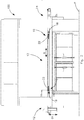
- thermoforming apparatus With reference to the aforesaid figures, with 100 a thermoforming apparatus has been indicated overall.
- thermoforming apparatus 100 may be suitable, in particular, for processing one or more products A made of plastics, in particular mould processing, for example hot moulding.
- the thermoforming apparatus 100 may comprise an inlet zone 12 in which the product A is loaded.
- the thermoforming apparatus 100 may comprise an outlet zone 14, arranged downstream of the aforesaid inlet zone 12, in which the product can be moved away from the thermoforming apparatus 100.
- the inlet zone 12 and the outlet zone 14 are arranged along a substantially horizontal feeding direction 8, i.e. a direction parallel to a plane P on which the thermoforming apparatus 100 rests.
- the thermoforming apparatus 100 may further comprise a processing zone 13 arranged downstream of the inlet zone 12 to perform moulding processing, or thermoforming, on the product A.
- the processing zone 13 there are moulds and other components that are of known type and are not shown that are suitable for performing moulding processing/thermoforming on the product. They will not therefore be described.
- the product A made of plastics that are processed in the thermoforming apparatus 100 may be made in the form of a slab, sheet or film.
- the product A may be in the form of a strip, where "strip" means a product that has three set dimensions, a first dimension (for example the thickness) being considerably less than a second and a third dimension (for example width and a length).
- the second and the third dimension (width and length) extend on another plane (not shown) parallel to the plane P whilst the first dimension extends transversely to the other plane.
- the fact that the product comprises two dimensions that prevail over the thickness means that two faces are defined, i.e. a first face 3 and a second face 6 that are opposite one another, as visible in Figures 4 to 6 .
- conveying means may be provided that is arranged for conveying the product A along the feeding direction 8 between the inlet zone 12 and the outlet zone 14.
- the conveying means may be of the closed loop type and may comprise cogged conveying means 1.
- the cogged conveying means 1 may comprise a toothed conveyor of known type, for example comprising a driven pulley and an idler pulley, between which a closed-loop chain may be fitted (or alternatively a belt or other flexible conveying element).
- the cogged conveying means 1 may extend in a direction parallel to the feeding direction 8; in one embodiment of the invention shown in Figure 1 , the cogged conveying means 1 comprises a first toothed conveyor 1a arranged on a first side edge of the thermoforming apparatus 100, and a second toothed conveyor 1b arranged on a second side edge of the thermoforming apparatus 100, the aforesaid second edge being opposite the first edge.
- the first toothed conveyor 1a and the second toothed conveyor 1b are arranged in a specular manner on the first edge and on the second edge of the thermoforming apparatus 100.
- the arrangement of the first 1a and of the second 1b toothed conveyor enables the product A to be conveyed along the feeding direction 8 without them occupying the space dedicated to the processing/moulding operation of the product A.
- the first 1a and the second 1b toothed conveyor are provided with a plurality of teeth 4 sized for engaging with at least the first face 3 of the product A.
- the teeth 4 may be arranged in a row along the feeding direction 8 between the inlet zone 12 and the outlet zone 14 of the thermoforming apparatus 100.
- the teeth 4 , 5 , 6 with the numeric reference 4 only one tooth of the row has been indicated.
- the teeth of the first toothed conveyor 1a are substantially the same in shape and size as the teeth of the second toothed conveyor 1b.
- the first face 3 of the product A that engages with the tooth 4 is the lower face of the product A.
- the product A is then arranged and locked on the cogged conveying means 1.
- the teeth 4 of the first toothed conveyor 1a may engage with a first abutting portion 15 of the first face 3 of the product A
- the teeth of the second toothed conveyor 1b may engage with a second abutting portion (not shown) of the aforesaid first face 3, the second abutting portion being opposite the first abutting portion 15.
- the teeth 4 may engage with the first face 3, making an incision on the first face 3 and traversing the first face 3 partially or can traverse the entire thickness of the product A.
- thermoforming apparatus 100 for example the first edge where the first toothed conveyor 1a is arranged and the first abutting portion 15 of the first face 3 of the product A. It remains understood that on the second edge that is not shown, in a manner that is specular to the first edge, the second toothed conveyor 1b and the second abutting portion of the first face of the product are arranged.
- thermoforming apparatus 100 in particular in the vicinity of the cogged conveying means 1, at least one extracting device 10 may fitted that is arranged for moving the product A, in particular extracted from the cogged conveying means 1.
- the extracting device 10 comprises first guide means 2 that faces, and is arranged for supporting, the first face 3 of the product A.
- the first guide means 2 is fitted to the first side edge in the vicinity of the first toothed conveyor 1a.
- the first guide means 2 faces in particular a first end portion 16 of the first face 3.
- the end portion 16 may be more external than the abutting portion 15.
- the end portion 16 may be arranged in the vicinity of, or can be adjacent to, the abutting portion 15.
- the extracting device 10 comprises further first guide means, which may be structurally identical to the first guide means 2, which is arranged for supporting the first face 3 of the product A.
- the further first guide means is arranged in the second side edge of the thermoforming apparatus 100 in the vicinity of the second toothed conveyor 1b.
- the further first guide means faces in particular a second end portion (not shown) of the first face 3, opposite the end portion 16.
- first guide means 2 or to the further first guide means, they being structurally the same as one another.
- the first guide means 2 may extend in the same direction as the cogged conveying means 1.
- the first guide means 2 may have substantially the same extent as the cogged conveying means 1 so as to support the product A in all the zones of the thermoforming apparatus 100.
- the first guide means 2 may comprise for example a plate, sized to support the first face 3 of the product.
- the plate faces the end portion 16 and is intended to come into contact with the latter, as will be explained below.
- the extracting device 10 further comprises second guide means 5 that faces a second face 6 of the product A.
- the second face 6 being opposite and substantially parallel to the first face 3.
- the second guide means 5 may be structurally identical to the first guide means 2.
- the second guide means 5 is fitted to the first side edge of the thermoforming apparatus 100.
- the second guide means 5 may be arranged at a set distance measured along a first direction D1 from the first guide means 2.
- the first direction D1 may be oriented transversely to one of the faces of the product A, for example to the first face 3.
- the first direction D1 may be substantially orthogonal to one of the faces of the product A, for example to the first face 3.
- the first direction D1 may be oriented transversely to the feeding direction 8.
- the second guide means 5 faces in particular a first strip portion 17 of the second face 6.
- the first strip portion 17 is substantially aligned on the first end portion 16 along the first direction D1.
- the extracting device 10 comprises further second guide means structurally identical to the second guide means 5, which also faces the second face 6.
- the further second guide means is arranged (in a specular manner) on the second side edge of the machine tool 100 and may be arranged at a set distance from the further first guide means along the first direction D1.
- the further second guide means faces in particular a second strip portion (not shown) of the second face 6, the second strip portion being opposite (specular to) the first strip portion.
- the second guide means 5 may comprise a plate facing the strip portion 17 of the second face 6.
- the second guide means 5 is oriented substantially parallel to the first guide means 2 and may extend in the same direction as the first guide means 2.
- the first guide means 2 may be movable along the first direction D1 between a first position in which the aforesaid first guide means 2 is near a root 4a of at least one tooth of the plurality of teeth 4 and the product A is engaged and locked on the plurality of teeth 4 of the cogged conveying means 1, and a second position in which the first guide means 2 is near a tip 4b of the tooth of the plurality of teeth 4 and supports the first face 3 of the product A, the latter being disengaged from the plurality of teeth 4.
- the first guide means 2 in the first position is placed at a set distance, measured along the first direction D1, from the end portion 16 of the first face 3 of the product A.
- the first guide means in the first position may be in contact with the aforesaid end portion of the first face of the product.
- the root 4a and the tip 4b of one of the teeth 4 are aligned substantially parallel to the first direction D1. In this manner, movement is facilitated, in particular extraction, or disengagement, of the product A from the cogged conveying means 1.
- the first guide means 2 and the second guide means 5 are connected to a first actuator 18 that is drivable to move the aforesaid first guide means 2 and second guide means 5 along the first direction D1.
- the second guide means 5 is further connected to a second actuator 22 that is drivable to move the aforesaid second guide means 5 along the second direction D2 that is transverse to the first direction D1.
- the first guide means 2 is connected to at least one first actuator 18 that is drivable to move the aforesaid first guide means 2 along the first direction D1.
- the first actuator 18 may comprise an actuator of linear type.
- first actuators connectable to the first guide means may vary.
- two actuators 18 are shown connected to the first guide means 2, one arranged in the vicinity of the inlet zone 12 and one in the vicinity of the outlet zone 14. The like occurs to the further first guide means fitted to the second edge of the thermoforming apparatus and is not illustrated.
- the first guide means 2 is connected to the first actuator 18 by a first support unit 19.
- the first support unit 19 is connected on one side to the first guide means 2 and on the other to a stem of the first actuator 18.
- the first support unit 19 may comprise a support bar 20 connected to the first guide means 2, for example in contact with the first guide means 2.
- the first support unit 20 may further comprise a bracket 21 connected, in particular by mechanical connection of known type, to the stem of the first actuator 18.
- the support bar 20 and the bracket 21 may be connected together, for example welded.
- the second guide means 5 is movable along the second direction D2 between a first configuration in which the second guide means 5 covers at least one portion of the second face 6, for example the strip portion 17 ( Figures 4 and 5 ), and a second configuration in which the second guide means 5 leaves this strip portion 17 free ( Figure 6 ) of the second face 6.
- the second guide means 5 spaced apart from and substantially parallel to the first guide means 2 whilst it moves along the second direction D2.
- the second guide means 5 is provided with at least one shaped portion 7 sized to house the plurality of teeth 4 of the cogged conveying means 1.
- a shaped portion is obtained, for example a groove, that extends parallel to the feeding direction 8 between the inlet zone 12 and the outlet zone 14.
- the shaped portion 7 is in a position that is substantially aligned on that of the teeth 4 along the direction D1, so as to define a housing seat for the teeth 4 of the cogged conveying means 1.
- the second guide means 5 is also movable along the first direction D1 between an engaged position in which the second guide means 5, preferably the shaped portion 7, is near the tip 4b of one of the teeth 4, and a disengaged position in which the second guide means 5, preferably the shaped portion 7, is spaced away from the aforesaid tip 4b.
- the second guide means 5 may be in contact, or not, with the strip portion 17 of the face 6 of the product.
- the second guide means 5 may be at least partially engaged by the tip 4b of the teeth.
- the shaped portion 7 may be at least partially engaged by the tip 4b of the teeth.
- the tips 4b thereof may be housed in the aforesaid shaped portion 7.
- the second guide means 5 is movable along the second direction D2 when it is near the aforesaid disengaged position.
- the second guide means 5 is connected to at least one second actuator 22 that is drivable to move the second guide means 5 along the second direction D2.
- the second actuator 22 may comprise an actuator of linear type.
- the number of second actuators 22 that are connectable to the second guide means 5 may vary.
- two actuators 22 are provided that are connected to the second guide means 5, one arranged in the vicinity of the inlet zone 12 and one in the vicinity of the outlet zone 14. The like occurs for the further second guide means that are on the second edge of the thermoforming apparatus and are not illustrated.
- the second actuator 22 and/or the second support unit 23 may be connected to the first actuator 18 to be movable along the first direction D1.
- the second actuator 22 and/or the second support unit 23 are connected to the first support unit 19.
- the second guide means 5 is connected to the second actuator 22 by a second support unit 23.
- the second actuator 22 may be driven to move the stem thereof along a driving direction M transverse to the first direction D1 and substantially parallel to the feeding direction 8.
- the second support unit 23 is arranged for modifying the direction of the movement set by the second actuator 22 (along the drive direction M) to move the second guide means 5 along the second direction D2, as explained below.
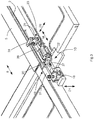
- the second support unit 23 may comprise a first connecting element 24 connected rotatably at a first end to the second guide means 5.
- the first connecting element 24 may comprise, for example, a rod, or a fork, hinged or pivoted on the first end on the second guide means 5.
- the first connecting element 24 is further connected rotatably to a second connecting element 25 in a second end (opposite the first end).
- the second connecting element 25 may comprise a stiff element, for example a lever.
- the first connecting element 24 and the second connecting element 25 are movable rotatably with respect to one another.
- the second connecting element 25 is connected rotatably to a base element 26 so as to be able to rotate around a rotation axis R parallel to the first direction D1.
- the base element 26 acts as a support element for the second connecting element 25.
- the base element 26 may be connected, for example by mechanical connecting means (of known type), to the support bar 20 of the first support unit 19 and is movable along the first direction D1.
- the second connecting element 25 is lastly connected rotatably to a stem of the second actuator 22 (for example hinged).
- the stem moves along the drive direction M for a set stroke matched by a rotation by a set angle ⁇ of the second connecting element 25 around the rotation axis R.
- the rotation of the second connecting element 25 moves along the second direction D2 the first connecting element 24, and consequently moves the second guide means 5 along the aforesaid second direction D2.
- the second actuator 22 may be connected to the support bar 20 of the first support unit 19 so as to be movable along the first direction D1.
- the second actuator 22 may be hinged on the support bar 20.
- the second actuator 22 may be connected rotatably, in particular hinged, on a third connecting element 27 fixed in a removable manner to the support bar 20.
- the third connecting element 27 may comprise a plate or a bracket.
- thermoforming apparatus 100 may actuate, in particular, a method for moving a product A made of plastics, as disclosed below.
- the operation of the thermoforming apparatus 100 may actuate a method for moving a product A made of plastics, in the form of a sheet or slab, by cogged conveying means 1 arranged on the thermoforming apparatus 100.
- the cogged conveying means 1 is provided with a plurality of teeth 4 arranged in a row along a feeding direction 8 between an inlet zone 12 and an outlet zone 14 of the thermoforming apparatus 100.
- the method may comprise the step of moving the first guide means 2 arranged on the thermoforming apparatus 100 and facing a first face 3 of the product A, along a first direction D1, oriented transversely to one of the faces of the product A, between a first position in which the first guide means 2 is near 4a a tooth of the plurality of teeth 4 and the product A is engaged and locked on the teeth 4, and a second position in which said first guide means 2 is near a tip 4b of one of the teeth 4 and supports the first face 3 of the product A that is disengaged from the teeth 4.
- the teeth may engage with an abutting portion 15 of the first face 3 of the product; the first guide means 2 may face an end portion 16 of the first face 3 of the product A, which is more external than, and in the vicinity of, the abutting portion 15.
- the root 4a and the tip 4b of the tooth of the plurality of teeth 4 are aligned substantially parallel to the first direction D1.
- the method for moving the product A may further envisage the step of moving the second guide means 5 arranged on the thermoforming apparatus 100 and facing a second face 6 of the product A, along a second direction D2 transverse to the first direction D1.
- the second face 6 is opposite the first face 3 along the first direction D1.
- the second guide means 5 is moved along the second direction D2 between a first configuration in which it covers at least one portion of the second face 6, and a second configuration in which it leaves free at least one portion of the second face 6.
- the second guide means 5 is arranged to cover a strip portion 17 of the second face 6 of the product A.
- the second guide means 5 is arranged at a set distance measured along the first direction D1 with respect to the first guide means 2.
- the second guide means 5 is oriented substantially parallel to the first guide means 2.
- the method for moving the product A may comprise the step of moving the second guide means 5 along the second direction D2 to make the second guide means 5 remain spaced apart and substantially parallel to the first guide means 2.
- the second guide means 5 is provided with at least one shaped portion 7 sized to house the plurality of teeth 4 of the cogged conveying means 1.
- the step of moving the first guide means 2 may also comprise the step of moving also the second guide means 5 along the first direction D1 between an engaged position in which the second guide means 5, preferably the shaped portion 7 of the aforesaid second guide means 5, is near the tip 4b of one of the teeth 4, and a disengaged position in which the second guide means 5, preferably the shaped portion 7, is spaced away from the aforesaid tip 4b.
- the second guide means 5 is moved along the second direction D2 when the latter is in the vicinity of said disengaged position.
- the first guide means 2 and second guide means 5 are both connected to a first actuator 18 that is drivable to move the first guide means 2 and second guide means 5 along the first direction D1.
- the second guide means 5 is further connected to a second actuator 22 that is drivable to move the second guide means 5 along the second direction D2.
- the extracting device in particular to the first and to the second guide means, the product is moved, in particular extracted from the cogged conveying means, without accidental falls and undesired movements occurring.
- thermoforming apparatus Owing to the extracting device, it is possible to move the product, in particular extract the product from the cogged conveying means and remove the product from the thermoforming apparatus, in any position between the inlet zone and an outlet zone of the aforesaid thermoforming apparatus.
- the product is not removable from the thermoforming apparatus, and thus secured between the first guide means and second guide means, until the second guide means is moved along the second direction and frees the second face of the product.
- the compactness of the extracting device enables the operator to lift and remove the product from the thermoforming apparatus with great facility; in fact, in a disengaged configuration the second guide means remains substantially parallel to the first guide means and has reduced vertical space take-up (measured along the first direction D1).
Landscapes
- Engineering & Computer Science (AREA)
- Mechanical Engineering (AREA)
- Blow-Moulding Or Thermoforming Of Plastics Or The Like (AREA)
- Encapsulation Of And Coatings For Semiconductor Or Solid State Devices (AREA)
- Injection Moulding Of Plastics Or The Like (AREA)
Applications Claiming Priority (1)
| Application Number | Priority Date | Filing Date | Title |
|---|---|---|---|
| IT102019000019055A IT201900019055A1 (it) | 2019-10-16 | 2019-10-16 | Metodo e Apparato per movimentare articoli in materiale plastico |
Publications (2)
| Publication Number | Publication Date |
|---|---|
| EP3808535A1 true EP3808535A1 (de) | 2021-04-21 |
| EP3808535B1 EP3808535B1 (de) | 2022-09-28 |
Family
ID=69701375
Family Applications (1)
| Application Number | Title | Priority Date | Filing Date |
|---|---|---|---|
| EP20201008.8A Active EP3808535B1 (de) | 2019-10-16 | 2020-10-09 | Verfahren und vorrichtung zum bewegen eines kunststoffartikels |
Country Status (3)
| Country | Link |
|---|---|
| EP (1) | EP3808535B1 (de) |
| IT (1) | IT201900019055A1 (de) |
| PL (1) | PL3808535T3 (de) |
Citations (3)
| Publication number | Priority date | Publication date | Assignee | Title |
|---|---|---|---|---|
| GB928346A (en) * | 1960-09-23 | 1963-06-12 | Design Ct Inc | Feed mechanism for sheet material forming machine |
| US4428723A (en) * | 1982-02-18 | 1984-01-31 | Thiel Alfons W | Apparatus for stretching a continuously advancing synthetic-resin web and feeding same stepwise to a thermoforming machine |
| EP0206838A2 (de) * | 1985-06-26 | 1986-12-30 | Continuous Graphics, Inc. | Verarbeitung von Endlosformularen |
-
2019
- 2019-10-16 IT IT102019000019055A patent/IT201900019055A1/it unknown
-
2020
- 2020-10-09 EP EP20201008.8A patent/EP3808535B1/de active Active
- 2020-10-09 PL PL20201008.8T patent/PL3808535T3/pl unknown
Patent Citations (3)
| Publication number | Priority date | Publication date | Assignee | Title |
|---|---|---|---|---|
| GB928346A (en) * | 1960-09-23 | 1963-06-12 | Design Ct Inc | Feed mechanism for sheet material forming machine |
| US4428723A (en) * | 1982-02-18 | 1984-01-31 | Thiel Alfons W | Apparatus for stretching a continuously advancing synthetic-resin web and feeding same stepwise to a thermoforming machine |
| EP0206838A2 (de) * | 1985-06-26 | 1986-12-30 | Continuous Graphics, Inc. | Verarbeitung von Endlosformularen |
Also Published As
| Publication number | Publication date |
|---|---|
| EP3808535B1 (de) | 2022-09-28 |
| IT201900019055A1 (it) | 2021-04-16 |
| PL3808535T3 (pl) | 2023-01-30 |
Similar Documents
| Publication | Publication Date | Title |
|---|---|---|
| CN106944529B (zh) | 补强钢片裁切载带包装机 | |
| EP2052979B1 (de) | Verpackungsvorrichtung mit ergonomischer Werkzeugänderung | |
| US9248929B2 (en) | Work station for a packaging machine and tool changing method | |
| EP0697959B1 (de) | Verfahren und vorrichtung zum wechseln von formen in warmformpressen | |
| EP2179656A1 (de) | System zum Stapeln und Entstapeln von Formeinheiten | |
| CN112061795B (zh) | 用于自动分离料盘的分盘装置 | |
| US20080134643A1 (en) | Web Packaging System with Ergonomic Tooling Change | |
| US9580193B2 (en) | Cutting station with complete cutting tool | |
| WO2012137082A1 (en) | Palletizing device and method | |
| EP2251266B1 (de) | Maschine zum Anbringen von Deckeln, insbesondere für Schalen und Körbe aus deformierbarem Material und dergleichen | |
| CN113148744A (zh) | 用于形成片材堆的片材堆垛机和方法 | |
| CN111409251A (zh) | 双胆并行压空吸塑成型机及其使用方法 | |
| CA1232529A (en) | Jam detection and removal for wrapping machine | |
| EP3808535B1 (de) | Verfahren und vorrichtung zum bewegen eines kunststoffartikels | |
| CN102079149B (zh) | 手提带自动装配机及装配方法 | |
| WO2004037652A1 (en) | Loader and packaging apparatus | |
| CN110304306A (zh) | 取盒输送机 | |
| CN210854369U (zh) | 自动出料堆码装置 | |
| CA3184507A1 (en) | Method for producing masses of food pieces and device for producing masses of food pieces | |
| KR19980076447A (ko) | 프레스가공에 의한 브랭크시트의 자동 적재장치 | |
| EP2363362A1 (de) | Behandlungsanordnung für gestapelte Behälter | |
| EP2308313B1 (de) | Anlage zur Behandlung eines Nahrungsmittels | |
| CN216470801U (zh) | 一种自动收卷转运装置 | |
| KR20170014650A (ko) | 파우치 정렬장치 | |
| EP4272559B1 (de) | Maschine zur herstellung eines nahrungsmittels, vorzugsweise eines kekses |
Legal Events
| Date | Code | Title | Description |
|---|---|---|---|
| PUAI | Public reference made under article 153(3) epc to a published international application that has entered the european phase |
Free format text: ORIGINAL CODE: 0009012 |
|
| STAA | Information on the status of an ep patent application or granted ep patent |
Free format text: STATUS: THE APPLICATION HAS BEEN PUBLISHED |
|
| AK | Designated contracting states |
Kind code of ref document: A1 Designated state(s): AL AT BE BG CH CY CZ DE DK EE ES FI FR GB GR HR HU IE IS IT LI LT LU LV MC MK MT NL NO PL PT RO RS SE SI SK SM TR |
|
| AX | Request for extension of the european patent |
Extension state: BA ME |
|
| STAA | Information on the status of an ep patent application or granted ep patent |
Free format text: STATUS: REQUEST FOR EXAMINATION WAS MADE |
|
| 17P | Request for examination filed |
Effective date: 20210608 |
|
| RBV | Designated contracting states (corrected) |
Designated state(s): AL AT BE BG CH CY CZ DE DK EE ES FI FR GB GR HR HU IE IS IT LI LT LU LV MC MK MT NL NO PL PT RO RS SE SI SK SM TR |
|
| GRAP | Despatch of communication of intention to grant a patent |
Free format text: ORIGINAL CODE: EPIDOSNIGR1 |
|
| STAA | Information on the status of an ep patent application or granted ep patent |
Free format text: STATUS: GRANT OF PATENT IS INTENDED |
|
| RIC1 | Information provided on ipc code assigned before grant |
Ipc: B65H 29/56 20060101ALI20220330BHEP Ipc: B29C 51/26 20060101AFI20220330BHEP |
|
| INTG | Intention to grant announced |
Effective date: 20220421 |
|
| GRAS | Grant fee paid |
Free format text: ORIGINAL CODE: EPIDOSNIGR3 |
|
| GRAA | (expected) grant |
Free format text: ORIGINAL CODE: 0009210 |
|
| STAA | Information on the status of an ep patent application or granted ep patent |
Free format text: STATUS: THE PATENT HAS BEEN GRANTED |
|
| AK | Designated contracting states |
Kind code of ref document: B1 Designated state(s): AL AT BE BG CH CY CZ DE DK EE ES FI FR GB GR HR HU IE IS IT LI LT LU LV MC MK MT NL NO PL PT RO RS SE SI SK SM TR |
|
| REG | Reference to a national code |
Ref country code: GB Ref legal event code: FG4D |
|
| REG | Reference to a national code |
Ref country code: CH Ref legal event code: EP |
|
| REG | Reference to a national code |
Ref country code: AT Ref legal event code: REF Ref document number: 1520979 Country of ref document: AT Kind code of ref document: T Effective date: 20221015 |
|
| REG | Reference to a national code |
Ref country code: DE Ref legal event code: R096 Ref document number: 602020005335 Country of ref document: DE |
|
| REG | Reference to a national code |
Ref country code: IE Ref legal event code: FG4D |
|
| REG | Reference to a national code |
Ref country code: LT Ref legal event code: MG9D |
|
| PG25 | Lapsed in a contracting state [announced via postgrant information from national office to epo] |
Ref country code: SE Free format text: LAPSE BECAUSE OF FAILURE TO SUBMIT A TRANSLATION OF THE DESCRIPTION OR TO PAY THE FEE WITHIN THE PRESCRIBED TIME-LIMIT Effective date: 20220928 Ref country code: RS Free format text: LAPSE BECAUSE OF FAILURE TO SUBMIT A TRANSLATION OF THE DESCRIPTION OR TO PAY THE FEE WITHIN THE PRESCRIBED TIME-LIMIT Effective date: 20220928 Ref country code: NO Free format text: LAPSE BECAUSE OF FAILURE TO SUBMIT A TRANSLATION OF THE DESCRIPTION OR TO PAY THE FEE WITHIN THE PRESCRIBED TIME-LIMIT Effective date: 20221228 Ref country code: LV Free format text: LAPSE BECAUSE OF FAILURE TO SUBMIT A TRANSLATION OF THE DESCRIPTION OR TO PAY THE FEE WITHIN THE PRESCRIBED TIME-LIMIT Effective date: 20220928 Ref country code: LT Free format text: LAPSE BECAUSE OF FAILURE TO SUBMIT A TRANSLATION OF THE DESCRIPTION OR TO PAY THE FEE WITHIN THE PRESCRIBED TIME-LIMIT Effective date: 20220928 Ref country code: FI Free format text: LAPSE BECAUSE OF FAILURE TO SUBMIT A TRANSLATION OF THE DESCRIPTION OR TO PAY THE FEE WITHIN THE PRESCRIBED TIME-LIMIT Effective date: 20220928 |
|
| REG | Reference to a national code |
Ref country code: NL Ref legal event code: MP Effective date: 20220928 |
|
| REG | Reference to a national code |
Ref country code: AT Ref legal event code: MK05 Ref document number: 1520979 Country of ref document: AT Kind code of ref document: T Effective date: 20220928 |
|
| PG25 | Lapsed in a contracting state [announced via postgrant information from national office to epo] |
Ref country code: HR Free format text: LAPSE BECAUSE OF FAILURE TO SUBMIT A TRANSLATION OF THE DESCRIPTION OR TO PAY THE FEE WITHIN THE PRESCRIBED TIME-LIMIT Effective date: 20220928 Ref country code: GR Free format text: LAPSE BECAUSE OF FAILURE TO SUBMIT A TRANSLATION OF THE DESCRIPTION OR TO PAY THE FEE WITHIN THE PRESCRIBED TIME-LIMIT Effective date: 20221229 |
|
| PG25 | Lapsed in a contracting state [announced via postgrant information from national office to epo] |
Ref country code: SM Free format text: LAPSE BECAUSE OF FAILURE TO SUBMIT A TRANSLATION OF THE DESCRIPTION OR TO PAY THE FEE WITHIN THE PRESCRIBED TIME-LIMIT Effective date: 20220928 Ref country code: RO Free format text: LAPSE BECAUSE OF FAILURE TO SUBMIT A TRANSLATION OF THE DESCRIPTION OR TO PAY THE FEE WITHIN THE PRESCRIBED TIME-LIMIT Effective date: 20220928 Ref country code: PT Free format text: LAPSE BECAUSE OF FAILURE TO SUBMIT A TRANSLATION OF THE DESCRIPTION OR TO PAY THE FEE WITHIN THE PRESCRIBED TIME-LIMIT Effective date: 20230130 Ref country code: ES Free format text: LAPSE BECAUSE OF FAILURE TO SUBMIT A TRANSLATION OF THE DESCRIPTION OR TO PAY THE FEE WITHIN THE PRESCRIBED TIME-LIMIT Effective date: 20220928 Ref country code: CZ Free format text: LAPSE BECAUSE OF FAILURE TO SUBMIT A TRANSLATION OF THE DESCRIPTION OR TO PAY THE FEE WITHIN THE PRESCRIBED TIME-LIMIT Effective date: 20220928 Ref country code: AT Free format text: LAPSE BECAUSE OF FAILURE TO SUBMIT A TRANSLATION OF THE DESCRIPTION OR TO PAY THE FEE WITHIN THE PRESCRIBED TIME-LIMIT Effective date: 20220928 |
|
| PG25 | Lapsed in a contracting state [announced via postgrant information from national office to epo] |
Ref country code: SK Free format text: LAPSE BECAUSE OF FAILURE TO SUBMIT A TRANSLATION OF THE DESCRIPTION OR TO PAY THE FEE WITHIN THE PRESCRIBED TIME-LIMIT Effective date: 20220928 Ref country code: IS Free format text: LAPSE BECAUSE OF FAILURE TO SUBMIT A TRANSLATION OF THE DESCRIPTION OR TO PAY THE FEE WITHIN THE PRESCRIBED TIME-LIMIT Effective date: 20230128 Ref country code: EE Free format text: LAPSE BECAUSE OF FAILURE TO SUBMIT A TRANSLATION OF THE DESCRIPTION OR TO PAY THE FEE WITHIN THE PRESCRIBED TIME-LIMIT Effective date: 20220928 |
|
| REG | Reference to a national code |
Ref country code: BE Ref legal event code: MM Effective date: 20221031 |
|
| P01 | Opt-out of the competence of the unified patent court (upc) registered |
Effective date: 20230519 |
|
| REG | Reference to a national code |
Ref country code: DE Ref legal event code: R097 Ref document number: 602020005335 Country of ref document: DE |
|
| PG25 | Lapsed in a contracting state [announced via postgrant information from national office to epo] |
Ref country code: NL Free format text: LAPSE BECAUSE OF FAILURE TO SUBMIT A TRANSLATION OF THE DESCRIPTION OR TO PAY THE FEE WITHIN THE PRESCRIBED TIME-LIMIT Effective date: 20220928 Ref country code: MC Free format text: LAPSE BECAUSE OF FAILURE TO SUBMIT A TRANSLATION OF THE DESCRIPTION OR TO PAY THE FEE WITHIN THE PRESCRIBED TIME-LIMIT Effective date: 20220928 Ref country code: LU Free format text: LAPSE BECAUSE OF NON-PAYMENT OF DUE FEES Effective date: 20221009 Ref country code: AL Free format text: LAPSE BECAUSE OF FAILURE TO SUBMIT A TRANSLATION OF THE DESCRIPTION OR TO PAY THE FEE WITHIN THE PRESCRIBED TIME-LIMIT Effective date: 20220928 |
|
| PG25 | Lapsed in a contracting state [announced via postgrant information from national office to epo] |
Ref country code: DK Free format text: LAPSE BECAUSE OF FAILURE TO SUBMIT A TRANSLATION OF THE DESCRIPTION OR TO PAY THE FEE WITHIN THE PRESCRIBED TIME-LIMIT Effective date: 20220928 |
|
| PLBE | No opposition filed within time limit |
Free format text: ORIGINAL CODE: 0009261 |
|
| STAA | Information on the status of an ep patent application or granted ep patent |
Free format text: STATUS: NO OPPOSITION FILED WITHIN TIME LIMIT |
|
| 26N | No opposition filed |
Effective date: 20230629 |
|
| PG25 | Lapsed in a contracting state [announced via postgrant information from national office to epo] |
Ref country code: BE Free format text: LAPSE BECAUSE OF NON-PAYMENT OF DUE FEES Effective date: 20221031 |
|
| PG25 | Lapsed in a contracting state [announced via postgrant information from national office to epo] |
Ref country code: IE Free format text: LAPSE BECAUSE OF NON-PAYMENT OF DUE FEES Effective date: 20221009 |
|
| PG25 | Lapsed in a contracting state [announced via postgrant information from national office to epo] |
Ref country code: SI Free format text: LAPSE BECAUSE OF FAILURE TO SUBMIT A TRANSLATION OF THE DESCRIPTION OR TO PAY THE FEE WITHIN THE PRESCRIBED TIME-LIMIT Effective date: 20220928 Ref country code: FR Free format text: LAPSE BECAUSE OF NON-PAYMENT OF DUE FEES Effective date: 20221128 |
|
| PG25 | Lapsed in a contracting state [announced via postgrant information from national office to epo] |
Ref country code: CY Free format text: LAPSE BECAUSE OF FAILURE TO SUBMIT A TRANSLATION OF THE DESCRIPTION OR TO PAY THE FEE WITHIN THE PRESCRIBED TIME-LIMIT Effective date: 20220928 |
|
| PG25 | Lapsed in a contracting state [announced via postgrant information from national office to epo] |
Ref country code: MK Free format text: LAPSE BECAUSE OF FAILURE TO SUBMIT A TRANSLATION OF THE DESCRIPTION OR TO PAY THE FEE WITHIN THE PRESCRIBED TIME-LIMIT Effective date: 20220928 |
|
| REG | Reference to a national code |
Ref country code: CH Ref legal event code: PL |
|
| PG25 | Lapsed in a contracting state [announced via postgrant information from national office to epo] |
Ref country code: CH Free format text: LAPSE BECAUSE OF NON-PAYMENT OF DUE FEES Effective date: 20231031 |
|
| PG25 | Lapsed in a contracting state [announced via postgrant information from national office to epo] |
Ref country code: HU Free format text: LAPSE BECAUSE OF FAILURE TO SUBMIT A TRANSLATION OF THE DESCRIPTION OR TO PAY THE FEE WITHIN THE PRESCRIBED TIME-LIMIT; INVALID AB INITIO Effective date: 20201009 Ref country code: CH Free format text: LAPSE BECAUSE OF NON-PAYMENT OF DUE FEES Effective date: 20231031 Ref country code: BG Free format text: LAPSE BECAUSE OF FAILURE TO SUBMIT A TRANSLATION OF THE DESCRIPTION OR TO PAY THE FEE WITHIN THE PRESCRIBED TIME-LIMIT Effective date: 20220928 |
|
| PG25 | Lapsed in a contracting state [announced via postgrant information from national office to epo] |
Ref country code: MT Free format text: LAPSE BECAUSE OF FAILURE TO SUBMIT A TRANSLATION OF THE DESCRIPTION OR TO PAY THE FEE WITHIN THE PRESCRIBED TIME-LIMIT Effective date: 20220928 |
|
| GBPC | Gb: european patent ceased through non-payment of renewal fee |
Effective date: 20241009 |
|
| PG25 | Lapsed in a contracting state [announced via postgrant information from national office to epo] |
Ref country code: GB Free format text: LAPSE BECAUSE OF NON-PAYMENT OF DUE FEES Effective date: 20241009 |
|
| PGFP | Annual fee paid to national office [announced via postgrant information from national office to epo] |
Ref country code: PL Payment date: 20250929 Year of fee payment: 6 |
|
| PG25 | Lapsed in a contracting state [announced via postgrant information from national office to epo] |
Ref country code: TR Free format text: LAPSE BECAUSE OF FAILURE TO SUBMIT A TRANSLATION OF THE DESCRIPTION OR TO PAY THE FEE WITHIN THE PRESCRIBED TIME-LIMIT Effective date: 20220928 |
|
| PGFP | Annual fee paid to national office [announced via postgrant information from national office to epo] |
Ref country code: DE Payment date: 20251020 Year of fee payment: 6 |
|
| PGFP | Annual fee paid to national office [announced via postgrant information from national office to epo] |
Ref country code: IT Payment date: 20251013 Year of fee payment: 6 |