EP3808546A1 - Procede de fabrication d'une piece sous presse avec outil verrouillable en hauteur - Google Patents
Procede de fabrication d'une piece sous presse avec outil verrouillable en hauteur Download PDFInfo
- Publication number
- EP3808546A1 EP3808546A1 EP20202149.9A EP20202149A EP3808546A1 EP 3808546 A1 EP3808546 A1 EP 3808546A1 EP 20202149 A EP20202149 A EP 20202149A EP 3808546 A1 EP3808546 A1 EP 3808546A1
- Authority
- EP
- European Patent Office
- Prior art keywords
- dies
- die
- preform
- tool
- press
- Prior art date
- Legal status (The legal status is an assumption and is not a legal conclusion. Google has not performed a legal analysis and makes no representation as to the accuracy of the status listed.)
- Withdrawn
Links
Images


Classifications
-
- B—PERFORMING OPERATIONS; TRANSPORTING
- B29—WORKING OF PLASTICS; WORKING OF SUBSTANCES IN A PLASTIC STATE IN GENERAL
- B29C—SHAPING OR JOINING OF PLASTICS; SHAPING OF MATERIAL IN A PLASTIC STATE, NOT OTHERWISE PROVIDED FOR; AFTER-TREATMENT OF THE SHAPED PRODUCTS, e.g. REPAIRING
- B29C70/00—Shaping composites, i.e. plastics material comprising reinforcements, fillers or preformed parts, e.g. inserts
- B29C70/04—Shaping composites, i.e. plastics material comprising reinforcements, fillers or preformed parts, e.g. inserts comprising reinforcements only, e.g. self-reinforcing plastics
- B29C70/28—Shaping operations therefor
- B29C70/30—Shaping by lay-up, i.e. applying fibres, tape or broadsheet on a mould, former or core; Shaping by spray-up, i.e. spraying of fibres on a mould, former or core
- B29C70/34—Shaping by lay-up, i.e. applying fibres, tape or broadsheet on a mould, former or core; Shaping by spray-up, i.e. spraying of fibres on a mould, former or core and shaping or impregnating by compression, i.e. combined with compressing after the lay-up operation
- B29C70/345—Shaping by lay-up, i.e. applying fibres, tape or broadsheet on a mould, former or core; Shaping by spray-up, i.e. spraying of fibres on a mould, former or core and shaping or impregnating by compression, i.e. combined with compressing after the lay-up operation using matched moulds
-
- B—PERFORMING OPERATIONS; TRANSPORTING
- B29—WORKING OF PLASTICS; WORKING OF SUBSTANCES IN A PLASTIC STATE IN GENERAL
- B29C—SHAPING OR JOINING OF PLASTICS; SHAPING OF MATERIAL IN A PLASTIC STATE, NOT OTHERWISE PROVIDED FOR; AFTER-TREATMENT OF THE SHAPED PRODUCTS, e.g. REPAIRING
- B29C33/00—Moulds or cores; Details thereof or accessories therefor
- B29C33/20—Opening, closing or clamping
- B29C33/202—Clamping means operating on closed or nearly closed mould parts, the clamping means being independently movable of the opening or closing means
-
- B—PERFORMING OPERATIONS; TRANSPORTING
- B29—WORKING OF PLASTICS; WORKING OF SUBSTANCES IN A PLASTIC STATE IN GENERAL
- B29C—SHAPING OR JOINING OF PLASTICS; SHAPING OF MATERIAL IN A PLASTIC STATE, NOT OTHERWISE PROVIDED FOR; AFTER-TREATMENT OF THE SHAPED PRODUCTS, e.g. REPAIRING
- B29C35/00—Heating, cooling or curing, e.g. crosslinking or vulcanising; Apparatus therefor
- B29C35/02—Heating or curing, e.g. crosslinking or vulcanizing during moulding, e.g. in a mould
-
- B—PERFORMING OPERATIONS; TRANSPORTING
- B29—WORKING OF PLASTICS; WORKING OF SUBSTANCES IN A PLASTIC STATE IN GENERAL
- B29C—SHAPING OR JOINING OF PLASTICS; SHAPING OF MATERIAL IN A PLASTIC STATE, NOT OTHERWISE PROVIDED FOR; AFTER-TREATMENT OF THE SHAPED PRODUCTS, e.g. REPAIRING
- B29C43/00—Compression moulding, i.e. applying external pressure to flow the moulding material; Apparatus therefor
- B29C43/02—Compression moulding, i.e. applying external pressure to flow the moulding material; Apparatus therefor of articles of definite length, i.e. discrete articles
- B29C43/04—Compression moulding, i.e. applying external pressure to flow the moulding material; Apparatus therefor of articles of definite length, i.e. discrete articles using movable moulds
-
- B—PERFORMING OPERATIONS; TRANSPORTING
- B29—WORKING OF PLASTICS; WORKING OF SUBSTANCES IN A PLASTIC STATE IN GENERAL
- B29C—SHAPING OR JOINING OF PLASTICS; SHAPING OF MATERIAL IN A PLASTIC STATE, NOT OTHERWISE PROVIDED FOR; AFTER-TREATMENT OF THE SHAPED PRODUCTS, e.g. REPAIRING
- B29C70/00—Shaping composites, i.e. plastics material comprising reinforcements, fillers or preformed parts, e.g. inserts
- B29C70/04—Shaping composites, i.e. plastics material comprising reinforcements, fillers or preformed parts, e.g. inserts comprising reinforcements only, e.g. self-reinforcing plastics
- B29C70/06—Fibrous reinforcements only
- B29C70/10—Fibrous reinforcements only characterised by the structure of fibrous reinforcements, e.g. hollow fibres
- B29C70/16—Fibrous reinforcements only characterised by the structure of fibrous reinforcements, e.g. hollow fibres using fibres of substantial or continuous length
- B29C70/24—Fibrous reinforcements only characterised by the structure of fibrous reinforcements, e.g. hollow fibres using fibres of substantial or continuous length oriented in at least three directions forming a three-dimensional [3D] structure
-
- B—PERFORMING OPERATIONS; TRANSPORTING
- B29—WORKING OF PLASTICS; WORKING OF SUBSTANCES IN A PLASTIC STATE IN GENERAL
- B29C—SHAPING OR JOINING OF PLASTICS; SHAPING OF MATERIAL IN A PLASTIC STATE, NOT OTHERWISE PROVIDED FOR; AFTER-TREATMENT OF THE SHAPED PRODUCTS, e.g. REPAIRING
- B29C70/00—Shaping composites, i.e. plastics material comprising reinforcements, fillers or preformed parts, e.g. inserts
- B29C70/04—Shaping composites, i.e. plastics material comprising reinforcements, fillers or preformed parts, e.g. inserts comprising reinforcements only, e.g. self-reinforcing plastics
- B29C70/28—Shaping operations therefor
- B29C70/40—Shaping or impregnating by compression not applied
- B29C70/42—Shaping or impregnating by compression not applied for producing articles of definite length, i.e. discrete articles
- B29C70/46—Shaping or impregnating by compression not applied for producing articles of definite length, i.e. discrete articles using matched moulds, e.g. for deforming sheet moulding compounds [SMC] or prepregs
-
- B—PERFORMING OPERATIONS; TRANSPORTING
- B29—WORKING OF PLASTICS; WORKING OF SUBSTANCES IN A PLASTIC STATE IN GENERAL
- B29C—SHAPING OR JOINING OF PLASTICS; SHAPING OF MATERIAL IN A PLASTIC STATE, NOT OTHERWISE PROVIDED FOR; AFTER-TREATMENT OF THE SHAPED PRODUCTS, e.g. REPAIRING
- B29C70/00—Shaping composites, i.e. plastics material comprising reinforcements, fillers or preformed parts, e.g. inserts
- B29C70/68—Shaping composites, i.e. plastics material comprising reinforcements, fillers or preformed parts, e.g. inserts by incorporating or moulding on preformed parts, e.g. inserts or layers, e.g. foam blocks
- B29C70/70—Completely encapsulating inserts
-
- B—PERFORMING OPERATIONS; TRANSPORTING
- B29—WORKING OF PLASTICS; WORKING OF SUBSTANCES IN A PLASTIC STATE IN GENERAL
- B29C—SHAPING OR JOINING OF PLASTICS; SHAPING OF MATERIAL IN A PLASTIC STATE, NOT OTHERWISE PROVIDED FOR; AFTER-TREATMENT OF THE SHAPED PRODUCTS, e.g. REPAIRING
- B29C70/00—Shaping composites, i.e. plastics material comprising reinforcements, fillers or preformed parts, e.g. inserts
- B29C70/68—Shaping composites, i.e. plastics material comprising reinforcements, fillers or preformed parts, e.g. inserts by incorporating or moulding on preformed parts, e.g. inserts or layers, e.g. foam blocks
- B29C70/86—Incorporated in coherent impregnated reinforcing layers, e.g. by winding
- B29C70/865—Incorporated in coherent impregnated reinforcing layers, e.g. by winding completely encapsulated
-
- B—PERFORMING OPERATIONS; TRANSPORTING
- B29—WORKING OF PLASTICS; WORKING OF SUBSTANCES IN A PLASTIC STATE IN GENERAL
- B29B—PREPARATION OR PRETREATMENT OF THE MATERIAL TO BE SHAPED; MAKING GRANULES OR PREFORMS; RECOVERY OF PLASTICS OR OTHER CONSTITUENTS OF WASTE MATERIAL CONTAINING PLASTICS
- B29B11/00—Making preforms
- B29B11/14—Making preforms characterised by structure or composition
- B29B11/16—Making preforms characterised by structure or composition comprising fillers or reinforcement
-
- B—PERFORMING OPERATIONS; TRANSPORTING
- B29—WORKING OF PLASTICS; WORKING OF SUBSTANCES IN A PLASTIC STATE IN GENERAL
- B29C—SHAPING OR JOINING OF PLASTICS; SHAPING OF MATERIAL IN A PLASTIC STATE, NOT OTHERWISE PROVIDED FOR; AFTER-TREATMENT OF THE SHAPED PRODUCTS, e.g. REPAIRING
- B29C33/00—Moulds or cores; Details thereof or accessories therefor
- B29C33/02—Moulds or cores; Details thereof or accessories therefor with incorporated heating or cooling means
- B29C2033/023—Thermal insulation of moulds or mould parts
-
- B—PERFORMING OPERATIONS; TRANSPORTING
- B29—WORKING OF PLASTICS; WORKING OF SUBSTANCES IN A PLASTIC STATE IN GENERAL
- B29C—SHAPING OR JOINING OF PLASTICS; SHAPING OF MATERIAL IN A PLASTIC STATE, NOT OTHERWISE PROVIDED FOR; AFTER-TREATMENT OF THE SHAPED PRODUCTS, e.g. REPAIRING
- B29C33/00—Moulds or cores; Details thereof or accessories therefor
- B29C33/20—Opening, closing or clamping
- B29C33/202—Clamping means operating on closed or nearly closed mould parts, the clamping means being independently movable of the opening or closing means
- B29C2033/207—Clamping means operating on closed or nearly closed mould parts, the clamping means being independently movable of the opening or closing means mould clamping by pivoting members
-
- B—PERFORMING OPERATIONS; TRANSPORTING
- B29—WORKING OF PLASTICS; WORKING OF SUBSTANCES IN A PLASTIC STATE IN GENERAL
- B29C—SHAPING OR JOINING OF PLASTICS; SHAPING OF MATERIAL IN A PLASTIC STATE, NOT OTHERWISE PROVIDED FOR; AFTER-TREATMENT OF THE SHAPED PRODUCTS, e.g. REPAIRING
- B29C35/00—Heating, cooling or curing, e.g. crosslinking or vulcanising; Apparatus therefor
- B29C35/02—Heating or curing, e.g. crosslinking or vulcanizing during moulding, e.g. in a mould
- B29C2035/0283—Thermal pretreatment of the plastics material
-
- B—PERFORMING OPERATIONS; TRANSPORTING
- B29—WORKING OF PLASTICS; WORKING OF SUBSTANCES IN A PLASTIC STATE IN GENERAL
- B29C—SHAPING OR JOINING OF PLASTICS; SHAPING OF MATERIAL IN A PLASTIC STATE, NOT OTHERWISE PROVIDED FOR; AFTER-TREATMENT OF THE SHAPED PRODUCTS, e.g. REPAIRING
- B29C35/00—Heating, cooling or curing, e.g. crosslinking or vulcanising; Apparatus therefor
- B29C35/16—Cooling
- B29C2035/1658—Cooling using gas
- B29C2035/1666—Cooling using gas dried air
-
- B—PERFORMING OPERATIONS; TRANSPORTING
- B29—WORKING OF PLASTICS; WORKING OF SUBSTANCES IN A PLASTIC STATE IN GENERAL
- B29C—SHAPING OR JOINING OF PLASTICS; SHAPING OF MATERIAL IN A PLASTIC STATE, NOT OTHERWISE PROVIDED FOR; AFTER-TREATMENT OF THE SHAPED PRODUCTS, e.g. REPAIRING
- B29C43/00—Compression moulding, i.e. applying external pressure to flow the moulding material; Apparatus therefor
- B29C43/02—Compression moulding, i.e. applying external pressure to flow the moulding material; Apparatus therefor of articles of definite length, i.e. discrete articles
- B29C43/04—Compression moulding, i.e. applying external pressure to flow the moulding material; Apparatus therefor of articles of definite length, i.e. discrete articles using movable moulds
- B29C2043/046—Compression moulding, i.e. applying external pressure to flow the moulding material; Apparatus therefor of articles of definite length, i.e. discrete articles using movable moulds travelling between different stations, e.g. feeding, moulding, curing stations
-
- B—PERFORMING OPERATIONS; TRANSPORTING
- B29—WORKING OF PLASTICS; WORKING OF SUBSTANCES IN A PLASTIC STATE IN GENERAL
- B29C—SHAPING OR JOINING OF PLASTICS; SHAPING OF MATERIAL IN A PLASTIC STATE, NOT OTHERWISE PROVIDED FOR; AFTER-TREATMENT OF THE SHAPED PRODUCTS, e.g. REPAIRING
- B29C33/00—Moulds or cores; Details thereof or accessories therefor
- B29C33/0033—Moulds or cores; Details thereof or accessories therefor constructed for making articles provided with holes
-
- B—PERFORMING OPERATIONS; TRANSPORTING
- B29—WORKING OF PLASTICS; WORKING OF SUBSTANCES IN A PLASTIC STATE IN GENERAL
- B29C—SHAPING OR JOINING OF PLASTICS; SHAPING OF MATERIAL IN A PLASTIC STATE, NOT OTHERWISE PROVIDED FOR; AFTER-TREATMENT OF THE SHAPED PRODUCTS, e.g. REPAIRING
- B29C33/00—Moulds or cores; Details thereof or accessories therefor
- B29C33/02—Moulds or cores; Details thereof or accessories therefor with incorporated heating or cooling means
-
- B—PERFORMING OPERATIONS; TRANSPORTING
- B29—WORKING OF PLASTICS; WORKING OF SUBSTANCES IN A PLASTIC STATE IN GENERAL
- B29C—SHAPING OR JOINING OF PLASTICS; SHAPING OF MATERIAL IN A PLASTIC STATE, NOT OTHERWISE PROVIDED FOR; AFTER-TREATMENT OF THE SHAPED PRODUCTS, e.g. REPAIRING
- B29C43/00—Compression moulding, i.e. applying external pressure to flow the moulding material; Apparatus therefor
- B29C43/02—Compression moulding, i.e. applying external pressure to flow the moulding material; Apparatus therefor of articles of definite length, i.e. discrete articles
-
- B—PERFORMING OPERATIONS; TRANSPORTING
- B29—WORKING OF PLASTICS; WORKING OF SUBSTANCES IN A PLASTIC STATE IN GENERAL
- B29C—SHAPING OR JOINING OF PLASTICS; SHAPING OF MATERIAL IN A PLASTIC STATE, NOT OTHERWISE PROVIDED FOR; AFTER-TREATMENT OF THE SHAPED PRODUCTS, e.g. REPAIRING
- B29C43/00—Compression moulding, i.e. applying external pressure to flow the moulding material; Apparatus therefor
- B29C43/32—Component parts, details or accessories; Auxiliary operations
- B29C43/52—Heating or cooling
-
- B—PERFORMING OPERATIONS; TRANSPORTING
- B29—WORKING OF PLASTICS; WORKING OF SUBSTANCES IN A PLASTIC STATE IN GENERAL
- B29C—SHAPING OR JOINING OF PLASTICS; SHAPING OF MATERIAL IN A PLASTIC STATE, NOT OTHERWISE PROVIDED FOR; AFTER-TREATMENT OF THE SHAPED PRODUCTS, e.g. REPAIRING
- B29C53/00—Shaping by bending, folding, twisting, straightening or flattening; Apparatus therefor
- B29C53/80—Component parts, details or accessories; Auxiliary operations
- B29C53/82—Cores or mandrels
- B29C53/821—Mandrels especially adapted for winding and joining
- B29C53/824—Mandrels especially adapted for winding and joining collapsible, e.g. elastic or inflatable; with removable parts, e.g. for regular shaped, straight tubular articles
-
- B—PERFORMING OPERATIONS; TRANSPORTING
- B29—WORKING OF PLASTICS; WORKING OF SUBSTANCES IN A PLASTIC STATE IN GENERAL
- B29C—SHAPING OR JOINING OF PLASTICS; SHAPING OF MATERIAL IN A PLASTIC STATE, NOT OTHERWISE PROVIDED FOR; AFTER-TREATMENT OF THE SHAPED PRODUCTS, e.g. REPAIRING
- B29C70/00—Shaping composites, i.e. plastics material comprising reinforcements, fillers or preformed parts, e.g. inserts
- B29C70/04—Shaping composites, i.e. plastics material comprising reinforcements, fillers or preformed parts, e.g. inserts comprising reinforcements only, e.g. self-reinforcing plastics
- B29C70/28—Shaping operations therefor
- B29C70/30—Shaping by lay-up, i.e. applying fibres, tape or broadsheet on a mould, former or core; Shaping by spray-up, i.e. spraying of fibres on a mould, former or core
- B29C70/38—Automated lay-up, e.g. using robots, laying filaments according to predetermined patterns
-
- B—PERFORMING OPERATIONS; TRANSPORTING
- B29—WORKING OF PLASTICS; WORKING OF SUBSTANCES IN A PLASTIC STATE IN GENERAL
- B29L—INDEXING SCHEME ASSOCIATED WITH SUBCLASS B29C, RELATING TO PARTICULAR ARTICLES
- B29L2031/00—Other particular articles
- B29L2031/06—Rods, e.g. connecting rods, rails, stakes
-
- F—MECHANICAL ENGINEERING; LIGHTING; HEATING; WEAPONS; BLASTING
- F16—ENGINEERING ELEMENTS AND UNITS; GENERAL MEASURES FOR PRODUCING AND MAINTAINING EFFECTIVE FUNCTIONING OF MACHINES OR INSTALLATIONS; THERMAL INSULATION IN GENERAL
- F16C—SHAFTS; FLEXIBLE SHAFTS; ELEMENTS OR CRANKSHAFT MECHANISMS; ROTARY BODIES OTHER THAN GEARING ELEMENTS; BEARINGS
- F16C2220/00—Shaping
- F16C2220/02—Shaping by casting
- F16C2220/06—Shaping by casting in situ casting or moulding
-
- F—MECHANICAL ENGINEERING; LIGHTING; HEATING; WEAPONS; BLASTING
- F16—ENGINEERING ELEMENTS AND UNITS; GENERAL MEASURES FOR PRODUCING AND MAINTAINING EFFECTIVE FUNCTIONING OF MACHINES OR INSTALLATIONS; THERMAL INSULATION IN GENERAL
- F16C—SHAFTS; FLEXIBLE SHAFTS; ELEMENTS OR CRANKSHAFT MECHANISMS; ROTARY BODIES OTHER THAN GEARING ELEMENTS; BEARINGS
- F16C2220/00—Shaping
- F16C2220/28—Shaping by winding impregnated fibres
-
- F—MECHANICAL ENGINEERING; LIGHTING; HEATING; WEAPONS; BLASTING
- F16—ENGINEERING ELEMENTS AND UNITS; GENERAL MEASURES FOR PRODUCING AND MAINTAINING EFFECTIVE FUNCTIONING OF MACHINES OR INSTALLATIONS; THERMAL INSULATION IN GENERAL
- F16C—SHAFTS; FLEXIBLE SHAFTS; ELEMENTS OR CRANKSHAFT MECHANISMS; ROTARY BODIES OTHER THAN GEARING ELEMENTS; BEARINGS
- F16C7/00—Connecting-rods or like links pivoted at both ends; Construction of connecting-rod heads
- F16C7/02—Constructions of connecting-rods with constant length
- F16C7/026—Constructions of connecting-rods with constant length made of fibre reinforced resin
Definitions
- the present invention relates to a method for manufacturing, using a press, a part made of composite material, for example a three-dimensional or solid part, such as an articulation or a connecting rod, while limiting the time of use of the press.
- This process allows in particular the manufacture of three-dimensional and / or massive parts while giving them high mechanical strength.
- the time required for the solidification of the thermoplastic resin may, depending on the mass and the geometry of the part, be greater than several tens of minutes during which the press maintains the part under pressure and is therefore unavailable to receive a new part to be die-stamped.
- the object of the invention is therefore to propose a method for manufacturing parts made of composite material with a thermoplastic matrix which makes it possible to limit the time of use of the press.
- the press is only used to bring the dies together and to shape the preformed part. Maintaining the preformed part under pressure during its cooling is ensured here by the joining of the dies in a close position, which makes it possible to remove the dies from the press without waiting for the resin to solidify, and therefore to release the press which is then available to receive other shaping tools.
- the production of the preform comprises the step of placing the long reinforcing fibers and the resin in a preforming tool.
- At least one insert is placed in the preforming tool so that the latter is integrated into the material of the preform.
- a subject of the invention is also a method as defined above, comprising the step of heating the forming tool to heat the preform before being transferred to the press.
- a subject of the invention is also a method as defined above, comprising the step of substantially maintaining the forming tool at temperature at least until it is removed from the press.
- the cooling of the forming tool is carried out by a flow of air diffused over the walls of said forming tool.
- the dies are joined together by a mechanical clamping device.
- the locking device is a mechanical clamping device.
- the double connecting rod 1 comprises a central bearing 2 oriented along a main axis AP, and two lateral arms 3 and 4 oriented transversely extending along an axis AT perpendicular to the axis AP, and which start from the central bearing 2 in directions opposites.
- Each arm is terminated by a corresponding bearing, and these lateral bearings, marked by 6 and 7, are oriented parallel to the central bearing 2.
- Each of the three bearings has a generally cylindrical wall shape with a circular base, the central bearing having a diameter significantly greater than that of the side bearings.
- the arm 3 comprises a flat wall 9 extending in a plane normal to the main direction AP, and two ribs 11 and 12 bordering the flat wall 9.
- Each rib is a wall extending perpendicularly to the flat wall 9, and which connects the central bearing 2 to the lateral bearing 6.
- the two ribs 11 and 12 are located on either side of the transverse axis AT which in turn passes through the central axis of each of the bearings 2, 6 and 7.
- the planar wall 9 has a relatively small thickness compared to the height of the bearings along the main direction AP, while the lateral ribs 11 and 12 each have a height close to the height of the bearings.
- the double connecting rod 1 has a shape which is symmetrical with respect to a plane normal to the transverse axis AT and containing the main axis AP which moreover coincides with the central axis of the central bearing 2.
- the arm 4 is the symmetrical to the arm 3, so that it also has two ribs of the same type.
- the double connecting rod 1 is also symmetrical with respect to a plane containing the transverse axis AT and the main axis AP, and it is also symmetrical with respect to a plane normal to the main axis AP and containing the transverse axis AT.
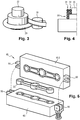
- This connecting rod is manufactured using the tools shown on the figures 2 to 5 , namely a preforming tool 20 and a die-forging or stamping tool 40.
- the preforming tool 20 here comprises a plate or sole 21 having a planar upper face 21a, this plate being provided with seven winding reliefs which are here pads, identified by the references 22 to 28. More concretely, the stud 22 corresponds to the bearing 6, the studs 23 and 24 correspond to the space located between the ribs 11 and 12 of the arm 3, the stud 25 corresponds to the central bearing 2, the studs 26 and 27 correspond to the space located between the ribs of the arm 4, and the stud 28 corresponds to the bearing 7.
- a strand 29 of reinforcing fibers impregnated with thermoplastic resin is wound on the preforming tool 20, around the pads 22-28, so as to follow a path which defines both the three bearings or yokes 2, 6, and 7, and the ribs 11 and 12 of the arm 3 as well as the corresponding ribs of the arm 4.
- the reinforcing fibers and the resin have a total mass equal to that of the double connecting rod 1.
- the strand 29 of fibers is arranged to s' extend along a path coinciding with the directions of stress of the part to be manufactured.
- the strand 29 of reinforcing fibers can be in different forms: it can be a set of fibers organized parallel to one another or in a helix; it can also be a set of fibers braided with one another to constitute a flexible braid extending generally in a main direction, but made up of spindle fibers oriented in multiple directions.
- the strand 29 impregnated with thermoplastic resin is wound around the various pads in such a way that, as visible on the figure 2 , it completely surrounds the lateral stud 22 to then pass on the same side of the studs 23 and 24 before changing sides to surround one half of the central stud 25 to then pass again on the same side of the studs 26 and 27 before completely surround the second lateral stud 28 to return along a symmetrical path as far as the first lateral stud 22, which corresponds to a full turn.
- the strand 29 can thus be wound over several turns around the different pads, the number of turns being conditioned by the diameter of the section of the strand with respect to the dimensions of the part to be manufactured.
- figure 2 which is given mainly for teaching purposes to understand the trajectory of the strand, it is wound over one and a half turns.
- the pads 22, 25 and 28 are shouldered pads: they are revolution pads comprising a cylindrical base extended by a coaxial stud of smaller diameter than the base. This shape of the studs 22, 25 and 28 makes it possible to produce bearings or yokes the internal surface of which is itself chamfered, that is to say that it comprises two zones having two different diameters.
- the strand 29 can be wound over a large number of turns being arranged so as to constitute a single circumferential layer 30 around the base of the stud 22, and two concentric circumferential layers 31 and 32 around the upper end of the stud 22 which has a significantly smaller diameter than its base.
- the strand 29 impregnated with thermoplastic resin is wound on the hot preforming tool 20, so as to have the flexibility required to allow precise winding.
- the preforming tool 20 is of the heating type, and the winding as such can be carried out by means of a robotic arm.
- the preform 33 When the preform 33 is solidified, it is extracted from the preforming tool 20.
- the elements in relief that the pads 22-28 constitute are advantageously designed to be retractable relative to the plate 21 which carries them.
- the detachment of the preform is obtained by controlling the retraction of the studs 22-28 before grasping this preform 33 in order to place it in a die-forging tool 40.
- the die-forging tool 40 comprises a lower die 40.1 in which an indentation of the external shape of the double connecting rod 1 to be manufactured is machined, and an upper die 40.2 comprising a hollow shape complementary to the indentation.
- the lower die 40.1 rests on a thermally insulating plate 41 to which it is integral.
- the upper die 40.2 is deposited on the preform 33 so as to complete the die-forging tool 40.
- the die-forging tool 40 is then transferred to a heating device designed to heat the preform 33 to a temperature here between one hundred and sixty and two hundred degrees Celsius in order to obtain a softening of the thermoplastic resin before starting the die-forging cycle.
- the heating device can for example be an inductor, a continuous flow inductor, an oven, a continuous flow furnace or an infrared tunnel ...
- the lower die 40.1 and / or the upper die 40.2 may also be provided for heating.
- the die-forging tool 40 is enclosed in a thermally insulating box 42 in order to maintain the preform 33 at temperature.
- a body 42.1 forming with the plate 41 a container in which the lower die 40.1 is housed, and a cover 42.2 which covers the upper die 40.2 and partially covers the body 42.1 so as to be able to slide along said body 42.1 during bringing the upper die 40.2 closer together in a substantially vertical direction.
- the plate 41 and the box 42 are made of a material resistant to compression.
- the box 42 containing the die-forging tool 40 is then installed in a press.
- the die-forging cycle can then begin.
- the press is controlled to exert a predetermined press force P on the upper die 40.2 in order to bring said upper die 40.2 closer to the lower die 40.1 and to bring them into a predetermined close position in which the two dies 40.1, 40.2 are in position. contact.
- the lower die 40.1 and the upper die 40.2 cooperate together in such a way that the resin is contained, that is to say that it does not leak from the lower die 40.1. It is also ensured that no fiber protrudes from the lower matrix 40.1 to prevent it from being sheared by the upper matrix 40.2.
- a locking device 50 is actuated to secure said dies 40.1, 40.2 to each other and thus keep them in a close position without resorting to the press force.
- the locking device 50 is advantageously arranged on the sides of the die-forging tool 40 so as not to interfere with the press and the plate 41, and is operable through the box 42.
- the locking device 50 comprises for example two pivoting quick clamping assemblies 51 fixed on either side of the lower die 40.1.
- each clamping assembly comprises a base 51.1, one end of which is fixed to a lateral appendage of the lower die 40.1 and on which a support element 51.2 is mounted to pivot about a substantially vertical axis between a position released and a pivoted position in which the support element 51.2 is opposite a lateral appendage of the upper die 40.2.
- the support element 51.2 is adjustable in height between the pivoted position and a clamped position in which said support element 51.2 applies a clamping force on the appendage of the upper die 40.2 so as to oppose the withdrawal of this one.
- a manually operable control lever 51.3 makes it possible to bring the support element 51.2 from the disengaged position to the pivoted position, then from the pivoted position to the clamped position.
- the travel of the control lever 51.3 can be broken down into three successive rotations carried out in the same direction: the first rotation allows the support element 51.2 to be pivoted from the disengaged position to the pivoted position; the second rotation makes it possible to bring the support element 51.2 into contact with the appendage of the upper die 40.2; the third rotation makes it possible to apply to the support element 51.2 a clamping force on the appendage of the upper die 40.2.
- the control lever 51.3 can be replaced by a nut whose rotation is automated by the descent of a screwdriver.
- pivoting clamping assemblies intended to be connected to a hydraulic circuit in order to be hydraulically piloted. They are then advantageously coupled to a non-return valve making it possible to keep the support element in the tight position without necessarily having it connected to the hydraulic circuit.
- the figure 7B illustrates a variant 51 'of the swivel quick clamp assembly 51 in which the element support 51.2 'is brought from the pivoted position to the clamped position via the use of an eccentric cam 51.4' connected to a lever 51.3 '.
- the figure 8A illustrates a second type of locking device 50 for the dies 40.1, 40.2 comprising two latches 52.1 mounted to pivot on an appendage of the lower die 40.1 between a disengaged position and a tight position in which the latch 52.1 is housed in an appendage of the upper die 40.2 and exerts a clamping force on the latter under the action of a spring 52.2.
- the figure 8B illustrates a variant 52.1 ′ of the latch 52.1 in which the clamping force is provided by an eccentric cam 52.2 ′ connected to a lever 52.3 ′ and not by a spring.
- the figure 9 illustrates a third type of locking device 50 for the dies 40.1, 40.2 comprising two screws 53 each intended to be screwed onto one side of the die-forging tool 40 in fixing lugs arranged to secure the dies 40.1, 40.2 together.
- the screws 53 are here advantageously oriented in a direction inclined relative to the plate 41 so as to facilitate access to the heads of the screws 53 and to automate their tightening.
- the screws 53 can be replaced by studs screwed substantially vertically into the fixing lugs of the lower die 40.1 to pass through the fixing lug of the upper die 40.2 and to cooperate with nuts so as to secure the upper die 40.2. to the lower die 40.1.
- the figure 10 illustrates a fourth type of locking device 50 for the dies 40.1, 40.2 comprising two latches 54.1 with hooks fixed to the lower die 40.1 and intended to cooperate with counter-hooks 54.2 fixed on the upper die 40.2 to ensure the maintenance of the dies 40.1, 40.2 in the close position.
- the figure 11 illustrates a fifth type of locking device 50 for the dies 40.1, 40.2 comprising two hooks 55.1 mounted to pivot on either side of the upper die 40.2 between a disengaged position and a tight position in which each of the hooks 55.1 cooperates with a ring 55.2 fixed on the lower die 40.1.
- the clamping force is provided by the eccentric profile of the hook 55.1 as it is hooked in the ring 55.2.
- the figure 12 illustrates a sixth type of locking device 50 for the dies 40.1, 40.2 comprising four U-shaped clips 56 arranged two by two on either side of the die-forging tool 40 in a substantially vertical plane.
- One free end of the staples 56 is arranged to be inserted into a substantially horizontally extending hole in the lower die 40.1 while the other free end of the staples 56 is arranged to be inserted into a substantially horizontally extending hole in the die.
- the press force P is interrupted.
- the box 42 containing the die-forging tool 40 is then transferred to a temperature-maintaining station in which the die-forged part is maintained at a predetermined temperature for a predetermined period of time so that the thermoplastic resin correctly impregnates the fibers.
- the temperature and the duration are in particular determined as a function of the mass of the part and of the nature of the thermoplastic resin. Temperature maintenance can for example be carried out via an electric resistance oven, an infrared oven, a fixed or continuous oven ...
- the die-forging tool 40 is then transferred to a cooling station in which the box 42 is withdrawn in order to allow the said die-forging tool 40 and the part it contains to cool before proceeding with its demoulding.
- the cooling is carried out while maintaining the matrices secured together for the duration necessary for the solidification of the thermoplastic resin. It can be carried out in the open air or via a flow of air diffused over the walls of the die-forging tool 40 or on metal diffusers placed in contact with the die-forging tool 40 depending on the mass of said die-forging tool. die-forging 40 and the part, the nature of the thermoplastic resin and the time that we want to devote to it.
- the die-forging tool 40 is transferred to an extraction station in which the locking device 50 is deactivated.
- the upper die 40.2 can therefore be separated from the lower die 40.1 and a raw, undeformed double connecting rod 1 can be extracted from the die-forging tool 40.
- the manufacture of a part having a different geometry, the double connecting rod 1, is ensured with similar tools adapted to this other geometry.
- an insert in the preform 33 so that it is integrated into the finished part while being rigidly secured to the body of the finished part in order to facilitate, for example, the transfer of forces.
- Such an insert is typically an element of a nature other than the body of the part, such as for example an insert of the metal type, a sensor, a bearing, a part of assembly or fixing.
- the process includes then the step of placing in the preforming tool at least one insert so that the insert is integrated into the material of the preform 33.
- the insert or inserts are here arranged in the preforming tool 20 before placement of the fibers and the fibers are arranged to at least partially surround the insert and participate in its retention in the preform 33.
- this manufacturing process makes it possible to manufacture in composite material parts initially made of steel or the like, said parts in composite material having a lower weight and / or volume and comparable mechanical strength according to a given load case.
- This manufacturing process also makes it possible to limit the use of the press to shaping the part. An improvement in the production rate of the part can therefore be envisaged.
- the shaping tool is preferably arranged so that the part obtained has final characteristics of the part to be manufactured. This makes it possible to limit the machining times to be carried out after shaping.
- the method according to the invention makes it possible to manufacture parts having complex shapes, extending in three dimensions, and which can also be massive either in localized regions or over the entire part.
- the double connecting rod 1 is obtained by winding a single strand of fibers. But in the case of a part of more complex shape, it is quite possible to wind several strands corresponding for example to several parts of the part to be manufactured.
- reinforcing fibers are here pre-impregnated with thermoplastic resin, it is also possible to use dry fibers placed in a tool forming a mold in which the thermoplastic resin would be introduced subsequently, before the application of the press force.
- the fibers can be of any material capable of mechanically reinforcing the thermoplastic material given the desired performance and in particular of aramid, polyaramid, glass, carbon, etc.
- the preform can comprise fibers of different materials.
- the fibers are here long, that is to say they have a minimum length substantially of the order of the length of the part.
- the fibers preferably have a length at least substantially equal to an integer multiple - for example two, three, four or more - of the length of the part.
- some of the fibers may be short, i.e. have a length less than a length of the blank. Short fibers can be added as a complement in certain areas.
- Fibers having a function other than the reinforcement can also be added to the resin or combined with the reinforcement fibers, and for example optical fibers or any other fibers capable of transmitting a signal.
- These signal conductive fibers may for example have one end connected to a sensor embedded in the room and an opposite end opening out to the outside of the room to be connected to a signal processing unit.
- the preform of part 1 is here produced by hot winding a strand of fibers impregnated with resin, other methods can be used to make the preform.
- the method may include the step of compressing the preform before curing of the resin in order to obtain a predetermined fiber volume ratio.
- the resin can be in different thermoplastic materials and for example in: polypropylene, polyamide, acrylic, polyethylene sulfone (PES), polyetheretherketone (PEEK), polyetherketonketone (PEKK), polyetherimide (PEI) ...
- the die-forging tool 40 is here enclosed in the box 42 after having been reheated in the heating device, it can also be enclosed in said box 42 just before its transfer into said heating device.
- thermoplastic resin has an extended forming temperature range and the die-forging tool 40 has a large volume, in other words a large thermal inertia, it is not necessarily necessary to enclose the die-forging tool 40. in the insulating box 42.
- Cooling and / or temperature maintenance can be obtained by implementing a controlled thermal cycle.
- the means for locking the dies together can have any structure making it possible to temporarily fix the relative position of the dies.
Landscapes
- Engineering & Computer Science (AREA)
- Mechanical Engineering (AREA)
- Chemical & Material Sciences (AREA)
- Composite Materials (AREA)
- Textile Engineering (AREA)
- Physics & Mathematics (AREA)
- Health & Medical Sciences (AREA)
- Oral & Maxillofacial Surgery (AREA)
- Thermal Sciences (AREA)
- Forging (AREA)
- Casting Or Compression Moulding Of Plastics Or The Like (AREA)
Abstract
- réaliser une préforme de la pièce ;
- installer la préforme dans un outillage de mise en forme comprenant une matrice inférieure et une matrice supérieure qui comportent en creux une empreinte reproduisant une forme externe de la pièce à fabriquer ;
- appliquer à chaud à l'aide d'une presse un effort de presse sur les matrices pour amener les matrices dans une position rapprochée dans laquelle la préforme est pressée entre les deux matrices ;
- solidariser ensemble les matrices de manière à les maintenir en position rapprochée puis interrompre l'effort de presse ;
- retirer de la presse les matrices ainsi solidarisées et les refroidir ;
- désolidariser la matrice inférieure et la matrice supérieure pour en extraire la pièce ainsi formée.
Description
- La présente invention concerne un procédé pour fabriquer, à l'aide d'une presse, une pièce en matériau composite, par exemple une pièce tridimensionnelle ou massive, telle qu'une articulation ou une bielle, tout en limitant le temps d'utilisation de la presse.
- Il est connu de fabriquer des pièces en matériau composite en intégrant des fibres de renfort continues dans de la résine thermoplastique, et en procédant à la mise en forme des pièces sous presse.
- En pratique, ce procédé comprend généralement les étapes de :
- disposer des fibres de renfort continues orientées dans des directions prédéterminées et de la résine dans un outillage de préformage de façon à réaliser une préforme de la pièce ;
- installer la préforme dans un outillage de mise en forme comprenant une matrice inférieure et une matrice supérieure qui comportent en creux une empreinte reproduisant une forme externe de la pièce à fabriquer ;
- appliquer à chaud, à l'aide d'une presse, un effort de presse sur les matrices pour amener les matrices dans une position rapprochée dans laquelle la préforme est pressée entre les deux matrices ;
- refroidir la pièce matricée en maintenant l'effort de presse jusqu'à la solidification de la résine thermoplastique.
- Ce procédé, connu du document
FR-A-3032144 - Néanmoins, le temps nécessaire à la solidification de la résine thermoplastique peut, en fonction de la masse et de la géométrie de la pièce, être supérieur à plusieurs dizaines de minutes pendant lesquelles la presse maintient sous pression la pièce et est donc indisponible pour recevoir une nouvelle pièce à matricer.
- Dès lors, un tel procédé de fabrication peut être incompatible avec certaines industries exigeant une cadence de production élevée, comme par exemple l'industrie automobile, et cela d'autant plus que le temps d'utilisation de la presse pour maintenir la pièce sous pression est bien plus important que celui pour presser la préforme entre les deux matrices.
- L'invention a donc pour objet de proposer un procédé de fabrication de pièces en matériau composite à matrice thermoplastique permettant de limiter le temps d'utilisation de la presse.
- A cet effet, on propose, selon l'invention, un procédé pour fabriquer une pièce en matériau composite, comprenant les étapes de :
- réaliser une préforme de la pièce ;
- installer la préforme dans un outillage de mise en forme comprenant une matrice inférieure et une matrice supérieure qui comportent en creux une empreinte reproduisant une forme externe de la pièce à fabriquer ;
- appliquer à chaud, à l'aide d'une presse, un effort de presse sur les matrices pour amener les matrices dans une position rapprochée dans laquelle la préforme est pressée entre les deux matrices ;
- solidariser ensemble les matrices de manière à les maintenir en position rapprochée puis interrompre l'effort de presse ;
- retirer de la presse les matrices ainsi solidarisées et les refroidir ;
- désolidariser la matrice inférieure et la matrice supérieure pour en extraire la pièce ainsi formée.
- Ainsi, la presse n'est utilisée que pour rapprocher les matrices entre elles et mettre en forme la pièce préformée. Le maintien sous pression de la pièce préformée pendant son refroidissement est ici assuré par la solidarisation des matrices en position rapprochée, ce qui permet de retirer les matrices de la presse sans attendre la solidification de la résine, et donc de libérer la presse qui est alors disponible pour recevoir un autre outillage de mise en forme.
- De manière particulière, la réalisation de la préforme comporte l'étape de disposer des fibres longues de renfort et de la résine dans un outillage de préformage.
- De manière particulière, au moins un insert est placé dans l'outillage de préformage pour que celui-ci soit intégré dans le matériau de la préforme.
- L'invention a également pour objet un procédé tel que défini ci-dessus, comprenant l'étape de chauffer l'outillage de mise en forme pour réchauffer la préforme avant d'être transféré sous la presse.
- L'invention a également pour objet un procédé tel que défini ci-dessus, comprenant l'étape de sensiblement maintenir en température l'outillage de mise en forme au moins jusqu'à son retrait de la presse.
- De manière particulière, le refroidissement de l'outil de mise en forme est réalisé par un flux d'air diffusé sur des parois dudit outil de mise en forme.
- De manière particulière, la solidarisation des matrices est réalisée par un dispositif de serrage mécanique.
- L'invention concerne également un outil de matriçage pour la mise en œuvre d'un tel procédé, l'outil comprenant :
- une matrice inférieure et une matrice supérieure montée mobile par rapport à la matrice inférieure entre une position éloignée et une position rapprochée, les matrices comportant en creux une empreinte reproduisant une forme externe d'une pièce à fabriquer ; et
- un dispositif de verrouillage pouvant être commuté entre un état verrouillé dans lequel il empêche tout éloignement de la matrice supérieure par rapport à la matrice inférieure et un état déverrouillé dans lequel la matrice supérieure est libre de s'éloigner de la matrice inférieure.
- De manière particulière, le dispositif de verrouillage est un dispositif de serrage mécanique.
- L'invention sera mieux comprise à la lumière de la description qui suit, laquelle est purement illustrative et non limitative, et doit être lue en regard des dessins annexés, parmi lesquels :
- [
Fig.1 ] lafigure 1 est une vue en perspective d'une bielle double fabriquée avec le procédé selon l'invention ; - [
Fig.2 ] lafigure 2 montre en perspective le bobinage d'un toron de fibres de renfort autour des reliefs d'un outillage de bobinage pour fabriquer la bielle illustrée à lafigure 1 conformément à l'invention ; - [
Fig.3 ] lafigure 3 est une vue de détail montrant en perspective un relief de bobinage de l'outillage illustré à lafigure 2 sous forme de plot comportant un épaulement ; - [
Fig.4 ] lafigure 4 est une vue en coupe montrant une possibilité de bobinage d'un toron de fibres de renfort autour d'un plot à épaulement ; - [
Fig.5 ] lafigure 5 est une vue en perspective d'un outillage de matriçage dans lequel est installée une pièce en cours de matriçage ; - [
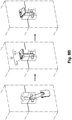
Fig.6 ] lafigure 6 est une vue schématique de différentes étapes du procédé selon l'invention ; - [
Fig.7A ] lafigure 7A est une vue en perspective d'un dispositif de verrouillage d'un outil de matriçage selon un premier mode de réalisation de l'invention ; - [
Fig.7B ] lafigure 7B est une vue en perspective d'une variante du dispositif de verrouillage illustré à lafigure 7A ; - [
Fig.8A ] lafigure 8A est une vue en perspective d'un dispositif de verrouillage d'un outil de matriçage selon un deuxième mode de réalisation de l'invention ; - [
Fig.8B ] lafigure 8B est une vue en perspective d'une variante du dispositif de verrouillage illustré à lafigure 8A ; - [
Fig.9 ] lafigure 9 est une vue en perspective d'un dispositif de verrouillage d'un outil de matriçage selon un troisième mode de réalisation de l'invention ; - [
Fig.10 ] lafigure 10 est une vue en perspective d'un dispositif de verrouillage d'un outil de matriçage selon un quatrième mode de réalisation de l'invention ; - [
Fig.11 ] lafigure 11 est une vue en perspective d'un dispositif de verrouillage d'un outil de matriçage selon un cinquième mode de réalisation de l'invention ; - [
Fig.12 ] lafigure 12 est une vue en perspective d'un dispositif de verrouillage d'un outil de matriçage selon un sixième mode de réalisation de l'invention. - Le procédé de l'invention est ici décrit en application à la fabrication d'une bielle double 1, étant entendu qu'il ne s'agit là que d'un exemple de mise en œuvre du procédé.
- La bielle double 1 comporte un palier central 2 orienté selon un axe principal AP, et deux bras latéraux 3 et 4 orientés transversalement en s'étendant selon un axe AT perpendiculaire à l'axe AP, et qui partent du palier central 2 dans des directions opposées. Chaque bras est terminé par un palier correspondant, et ces paliers latéraux, repérés par 6 et 7, sont orientés parallèlement au palier central 2.
- Chacun des trois paliers a une forme de paroi généralement cylindrique à base circulaire, le palier central ayant un diamètre significativement supérieur à celui des paliers latéraux.
- Le bras 3 comporte une paroi plane 9 s'étendant selon un plan normal à la direction principale AP, et deux nervures 11 et 12 bordant la paroi plane 9. Chaque nervure est une paroi s'étendant perpendiculairement à la paroi plane 9, et qui raccorde le palier central 2 au palier latéral 6. Les deux nervures 11 et 12 sont situées de part et d'autre de l'axe transversal AT qui passe quant à lui par l'axe central de chacun des paliers 2, 6 et 7.
- La paroi plane 9 a une épaisseur relativement faible par rapport à la hauteur des paliers le long de la direction principale AP, alors que les nervures latérales 11 et 12 ont chacune une hauteur proche de la hauteur des paliers.
- La bielle double 1 a une forme qui est symétrique par rapport à un plan normal à l'axe transversal AT et contenant l'axe principal AP qui par ailleurs coïncide avec l'axe central du palier central 2. Ainsi, le bras 4 est le symétrique du bras 3, de sorte qu'il comporte lui aussi deux nervures du même type.
- La bielle double 1 est également symétrique par rapport à un plan contenant l'axe transversal AT et l'axe principal AP, et elle est également symétrique par rapport à un plan normal à l'axe principal AP et contenant l'axe transversal AT.
- Cette bielle est fabriquée à l'aide des outillages représentés sur les
figures 2 à 5 , à savoir un outillage de préformage 20 et un outillage de matriçage ou estampage 40. - L'outillage de préformage 20 comporte ici une platine ou sole 21 ayant une face supérieure 21a plane, cette platine étant pourvue de sept reliefs de bobinage qui sont ici des plots, repérés par les références 22 à 28. Plus concrètement, le plot 22 correspond au palier 6, les plots 23 et 24 correspondent à l'espace situé entres les nervures 11 et 12 du bras 3, le plot 25 correspond au palier central 2, les plots 26 et 27 correspondent à l'espace situé entre les nervures du bras 4, et le plot 28 correspond au palier 7.
- Comme visible sur la
figure 2 , un toron 29 de fibres de renfort imprégné de résine thermoplastique est bobiné sur l'outillage de préformage 20, autour des plots 22-28, de manière à suivre une trajectoire qui délimite à la fois les trois paliers ou chapes 2, 6, et 7, et les nervures 11 et 12 du bras 3 ainsi que les nervures correspondantes du bras 4. Les fibres de renfort et la résine ont une masse totale égale à celle de la bielle double 1. Le toron 29 de fibres est disposé pour s'étendre selon une trajectoire coïncidant avec les directions de sollicitation de la pièce à fabriquer. - Le toron 29 de fibres de renfort peut se présenter sous différentes formes : il peut s'agir d'un ensemble de fibres organisées parallèlement les unes aux autres ou en hélice ; il peut également s'agir d'un ensemble de fibres tressées les unes avec les autres pour constituer une tresse souple s'étendant globalement selon une direction principale, mais constituée de fibres de fuseau orientées selon de multiples directions.
- Le toron 29 imprégné de résine thermoplastique est bobiné autour des différents plots de telle manière que, comme visible sur la
figure 2 , il entoure complètement le plot latéral 22 pour passer ensuite d'un même côté des plots 23 et 24 avant de changer de côté pour entourer une moitié du plot central 25 pour repasser ensuite d'un même côté des plots 26 et 27 avant d'entourer complètement le deuxième plot latéral 28 pour revenir selon une trajectoire symétrique jusqu'au premier plot latéral 22, ce qui correspond à un tour complet. - Le toron 29 peut ainsi être bobiné sur plusieurs tours autour des différents plots, le nombre de tours étant conditionné par le diamètre de la section du toron vis-à-vis des dimensions de la pièce à fabriquer. Dans l'exemple de la
figure 2 qui est donné à titre principalement didactique pour comprendre la trajectoire du toron, celui-ci est bobiné sur un tour et demi. - Comme visible sur les
figures 2 et3 , les plots 22, 25 et 28 sont des plots épaulés : il s'agit de plots de révolution comportant une embase cylindrique prolongée par un téton coaxial de plus faible diamètre que l'embase. Cette forme des plots 22, 25 et 28 permet de réaliser des paliers ou chapes dont la surface interne est elle-même chanfreinée, c'est-à-dire qu'elle comporte deux zones ayant deux diamètres différents. - En particulier, et comme visible sur les
figures 3 et 4 , le toron 29 peut être bobiné sur un nombre de tours important en étant agencé de façon à constituer une seule couche circonférentielle 30 autour de l'embase du plot 22, et deux couches circonférentielles concentriques 31 et 32 autour de l'extrémité supérieure du plot 22 qui présente un diamètre significativement plus faible que son embase. - Ainsi, différentes solutions peuvent être envisagées en ce qui concerne le bobinage du toron sur l'outillage de préformage 20, en fonction des particularités de formes que l'on souhaite obtenir au niveau de la pièce à fabriquer.
- Le toron 29 imprégné de résine thermoplastique est bobiné sur l'outillage de préformage 20 à chaud, de manière à avoir la souplesse requise pour permettre un bobinage précis. Avantageusement, l'outillage de préformage 20 est du type chauffant, et le bobinage en tant que tel peut être réalisé au moyen d'un bras robotisé.
- Lorsque le bobinage du toron 29 est entièrement terminé, il constitue une préforme 33 de la pièce à fabriquer. Cette préforme est laissée à refroidir pour qu'elle se solidifie dans sa forme propre.
- Lorsque la préforme 33 est solidifiée, elle est extraite de l'outillage de préformage 20. A ce titre, les éléments de relief que constituent les plots 22-28 sont avantageusement prévus rétractables par rapport à la platine 21 qui les porte. Dans ce cas, le détachement de la préforme est obtenu en commandant la rétraction des plots 22-28 avant de saisir cette préforme 33 pour la mettre en place dans un outillage de matriçage 40.
- En référence aux
figures 5 et6 , l'outil de matriçage 40 comprend une matrice inférieure 40.1 dans laquelle est usinée une empreinte de la forme externe de la bielle double 1 à fabriquer, et une matrice supérieure 40.2 comportant en creux une forme complémentaire de l'empreinte. La matrice inférieure 40.1 repose sur un plateau 41 isolant thermiquement dont elle est solidaire. - Lorsque la préforme 33 a été installée dans l'empreinte de la matrice inférieure 40.1, la matrice supérieure 40.2 est déposée sur la préforme 33 de façon à compléter l'outil de matriçage 40.
- L'outil de matriçage 40 est alors transféré dans un dispositif de chauffage agencé pour réchauffer la préforme 33 à une température ici comprise entre cent soixante et deux cent degrés Celsius afin d'obtenir un ramollissement de la résine thermoplastique avant de débuter le cycle de matriçage. Le dispositif de chauffage peut par exemple être un inducteur, un inducteur à passage continu, un four, un four à passage continu ou un tunnel à infrarouge... La matrice inférieure 40.1 et/ ou la matrice supérieure 40.2 peuvent également être prévues chauffantes.
- Après avoir été transféré dans le dispositif de chauffage, l'outil de matriçage 40 est enfermé dans un caisson 42 isolant thermiquement pour maintenir en température la préforme 33. Le caisson 42 est constitué d'un corps 42.1 formant avec le plateau 41 un conteneur dans lequel est logée la matrice inférieure 40.1, et d'un couvercle 42.2 venant coiffer la matrice supérieure 40.2 et recouvrir partiellement le corps 42.1 de manière à pouvoir coulisser le long dudit corps 42.1 lors d'un rapprochement de la matrice supérieure 40.2 selon une direction sensiblement verticale. Le plateau 41 et le caisson 42 sont réalisés dans un matériau résistant à la compression.
- Le caisson 42 contenant l'outil de matriçage 40 est ensuite installé sous une presse. Le cycle de matriçage peut alors débuter. Ainsi, la presse est commandée pour exercer un effort de presse P prédéterminé sur la matrice supérieure 40.2 afin de rapprocher ladite matrice supérieure 40.2 de la matrice inférieure 40.1 et de les amener dans une position rapprochée prédéterminée dans laquelle les deux matrices 40.1, 40.2 sont en contact.
- La matrice inférieure 40.1 et la matrice supérieure 40.2 coopèrent ensemble de telle manière que la résine soit contenue, c'est-à-dire qu'elle ne fuit pas de la matrice inférieure 40.1. On s'assure en outre qu'aucune fibre ne dépasse de la matrice inférieure 40.1 pour éviter qu'elle ne soit cisaillée par la matrice supérieure 40.2.
- Lorsque les matrices 40.1, 40.2 sont en position rapprochée, un dispositif de verrouillage 50 est actionné pour solidariser lesdites matrices 40.1, 40.2 entre elles et ainsi les maintenir en position rapprochée sans recourir à l'effort de presse.
- Le dispositif de verrouillage 50 est avantageusement agencé sur des côtés de l'outil de matriçage 40 afin de ne pas interférer avec la presse et le plateau 41, et est actionnable au travers du caisson 42.
- En référence à la
figure 7A , le dispositif de verrouillage 50 comprend par exemple deux ensembles de bridage rapide pivotant 51 fixés de part et d'autre de la matrice inférieure 40.1. De façon connue en soi, chaque ensemble de bridage comporte une embase 51.1 dont une extrémité est fixée sur un appendice latéral de la matrice inférieure 40.1 et sur lequel un élément d'appui 51.2 est monté pivotant autour d'un axe sensiblement vertical entre une position dégagée et une position pivotée dans laquelle l'élément d'appui 51.2 est en regard d'un appendice latéral de la matrice supérieure 40.2. L'élément d'appui 51.2 est ajustable en hauteur entre la position pivotée et une position serrée dans laquelle ledit élément d'appui 51.2 applique un effort de serrage sur l'appendice de la matrice supérieure 40.2 de manière à s'opposer au retrait de celle-ci. Un levier de commande 51.3 actionnable manuellement permet d'amener l'élément d'appui 51.2 de la position dégagée à la position pivotée, puis de la position pivotée à la position serrée. La course du levier de commande 51.3 peut se décomposer en trois rotations successives réalisées dans un même sens : la première rotation permet de faire pivoter l'élément d'appui 51.2 de la position dégagée à la position pivotée ; la deuxième rotation permet d'amener l'élément d'appui 51.2 au contact de l'appendice de la matrice supérieure 40.2 ; la troisième rotation permet de faire appliquer à l'élément d'appui 51.2 un effort de serrage sur l'appendice de la matrice supérieure 40.2. - Le levier de commande 51.3 peut être remplacé par un écrou dont la rotation est automatisée par la descente d'une visseuse.
- Il existe également des ensembles de bridage pivotants destinés à être reliés à un circuit hydraulique pour être pilotés hydrauliquement. Ils sont alors avantageusement couplés à un clapet anti-retour permettant de maintenir l'élément d'appui en position serrée sans nécessairement qu'il soit relié au circuit hydraulique.
- La
figure 7B illustre une variante 51' de l'ensemble de bridage rapide pivotant 51 dans laquelle l'élément d'appui 51.2' est amené de la position pivotée à la position serrée via l'utilisation d'une came excentrique 51.4' reliée à un levier 51.3'. - La
figure 8A illustre un deuxième type de dispositif de verrouillage 50 des matrices 40.1, 40.2 comprenant deux loquets 52.1 montés pivotant sur un appendice de la matrice inférieure 40.1 entre une position dégagée et une position serrée dans laquelle le loquet 52.1 est logé dans un appendice de la matrice supérieure 40.2 et exerce sur ce dernier un effort de serrage sous l'action d'un ressort 52.2. - La
figure 8B illustre une variante 52.1' du loquet 52.1 dans lequel l'effort de serrage est assuré par une came excentrique 52.2' reliée à un levier 52.3' et non par un ressort. - La
figure 9 illustre un troisième type de dispositif de verrouillage 50 des matrices 40.1, 40.2 comprenant deux vis 53 destinées chacune à être vissée sur un côté de l'outil de matriçage 40 dans des pattes de fixation agencées pour solidariser les matrices 40.1, 40.2 entre elles. Les vis 53 sont ici avantageusement orientées selon une direction inclinée par rapport au plateau 41 de manière à faciliter l'accès aux têtes des vis 53 et d'en automatiser le vissage. - En variante, les vis 53 peuvent être remplacées par des goujons vissés sensiblement verticalement dans les pattes de fixation de la matrice inférieure 40.1 pour traverser la patte de fixation de la matrice supérieure 40.2 et pour coopérer avec des écrous de manière à solidariser la matrice supérieure 40.2 à la matrice inférieure 40.1.
- La
figure 10 illustre un quatrième type de dispositif de verrouillage 50 des matrices 40.1, 40.2 comprenant deux grenouillères 54.1 à crochet fixées sur la matrice inférieure 40.1 et destinées à coopérer avec des contre-crochets 54.2 fixés sur la matrice supérieure 40.2 pour assurer le maintien des matrices 40.1, 40.2 en position rapprochée. - La
figure 11 illustre un cinquième type de dispositif de verrouillage 50 des matrices 40.1, 40.2 comprenant deux crochets 55.1 montés pivotant de part et d'autre de la matrice supérieure 40.2 entre une position dégagée et une position serrée dans laquelle chacun des crochets 55.1 coopère avec un anneau 55.2 fixé sur la matrice inférieure 40.1. L'effort de serrage est assuré par le profil excentrique du crochet 55.1 au fur et à mesure de son crochetage dans l'anneau 55.2. - La
figure 12 illustre un sixième type de dispositif de verrouillage 50 des matrices 40.1, 40.2 comprenant quatre agrafes 56 en forme de U disposées deux à deux de part et d'autre de l'outil de matriçage 40 dans un plan sensiblement vertical. Une extrémité libre des agrafes 56 est agencée pour être insérée dans un trou s'étendant sensiblement horizontalement dans la matrice inférieure 40.1 tandis que l'autre extrémité libre des agrafes 56 est agencée pour être insérée dans un trou s'étendant sensiblement horizontalement dans la matrice supérieure 40.2. - Lorsque les matrices 40.1, 40.2 sont solidarisées ensemble par le dispositif de verrouillage 50, l'effort de presse P est interrompu. Le caisson 42 contenant l'outil de matriçage 40 est alors transféré à un poste de maintien en température dans laquelle la pièce matricée est maintenue à une température prédéterminée pendant une durée prédéterminée de manière à ce que la résine thermoplastique imprègne correctement les fibres. La température et la durée sont notamment déterminées en fonction de la masse de la pièce et de la nature de la résine thermoplastique. Le maintien en température peut par exemple être réalisé via un four à résistance électrique, un four à infrarouge, un four fixe ou à passage continu...
- L'outil de matriçage 40 est ensuite transféré à un poste de refroidissement dans lequel le caisson 42 est retiré pour laisser refroidir ledit outillage de matriçage 40 ainsi que la pièce qu'il contient avant de procéder à son démoulage. Le refroidissement est réalisé tout en maintenant les matrices solidarisées ensemble pendant toute la durée nécessaire à la solidification de la résine thermoplastique. Il peut être réalisé à l'air libre ou via un flux d'air diffusé sur des parois de l'outil de matriçage 40 ou sur des diffuseurs métalliques placés au contact de l'outil de matriçage 40 en fonction de la masse dudit outil de matriçage 40 et de la pièce, de la nature de la résine thermoplastique et du temps que l'on veut y consacrer.
- Lorsque la résine thermoplastique est suffisamment solidifiée, l'outil de matriçage 40 est transféré à un poste d'extraction dans lequel le dispositif de verrouillage 50 est désactivé. La matrice supérieure 40.2 peut dès lors être désolidarisée de la matrice inférieure 40.1 et une double bielle 1 brute non déformée peut être extraite de l'outil de matriçage 40.
- Conformément à l'invention, la fabrication d'une pièce ayant une géométrie différente la bielle double 1 est assurée avec des outillages analogues adaptés à cette autre géométrie.
- Par ailleurs, il est possible de placer un insert dans la préforme 33 pour que celui-ci soit intégré à la pièce finie en étant rigidement solidarisé au corps de la pièce finie afin de faciliter par exemple les transferts d'efforts. Un tel insert est typiquement un élément d'une nature autre que le corps de la pièce, comme par exemple un insert de type métallique, un capteur, un palier, une partie de d'assemblage ou de fixation. Le procédé comprend alors l'étape de placer dans l'outillage de préformage au moins un insert pour que l'insert soit intégré dans le matériau de la préforme 33. A cette fin, le ou les inserts sont ici disposés dans l'outillage de préformage 20 avant placement des fibres et les fibres sont disposées pour entourer au moins en partie l'insert et participer à sa retenue dans la préforme 33.
- Ainsi, ce procédé de fabrication permet de fabriquer en matériau composite des pièces initialement fabriquées en acier ou autre, lesdites pièces en matériau composite ayant un poids et/ou un volume plus faible et une tenue mécanique comparable selon un cas de charge donné.
- Ce procédé de fabrication permet également de limiter l'utilisation de la presse à la mise en forme de la pièce. Une amélioration de la cadence de production de la pièce peut dès lors être envisagée.
- On notera que l'outillage de mise en forme est de préférence agencé pour que la pièce obtenue présente des caractéristiques finales de la pièce à fabriquer. Ceci permet de limiter les reprises d'usinage à réaliser après la mise en forme.
- Bien entendu, l'invention n'est pas limitée aux modes de réalisation décrits mais englobe toute variante entrant dans le champ de l'invention telle que définie par les revendications.
- Le procédé selon l'invention permet de fabriquer des pièces ayant des formes complexes, s'étendant selon les trois dimensions, et pouvant également être massives soit dans des régions localisées, soit sur l'ensemble de la pièce.
- La bielle double 1 est obtenue en bobinant un seul toron de fibres. Mais dans le cas d'une pièce de forme plus complexe, il est tout à fait possible de bobiner plusieurs torons correspondant par exemple à plusieurs parties de la pièce à fabriquer.
- Bien que les fibres de renfort soient ici pré-imprégnées de résine thermoplastique, on pourrait aussi utiliser des fibres sèches mises en place dans un outillage formant moule dans lequel la résine thermoplastique serait introduite ultérieurement, avant l'application de l'effort de presse.
- Les fibres peuvent être en tout matériau susceptible de renforcer mécaniquement le matériau thermoplastique compte tenu des performances recherchées et notamment en aramide, polyaramide, verre, carbone... La préforme peut comprendre des fibres de matériaux différents.
- Les fibres sont ici longues, c'est-à-dire qu'elles ont une longueur minimale sensiblement de l'ordre de la longueur de la pièce. Les fibres ont de préférence une longueur au moins sensiblement égale à un multiple entier -par exemple deux, trois, quatre ou plus- de la longueur de la pièce. Néanmoins, certaines des fibres peuvent être courtes, c'est-à-dire avoir une longueur inférieure à une longueur de la pièce brute. Des fibres courtes peuvent être rajoutées en complément dans certaines zones.
- Des fibres ayant une fonction autre que le renfort peuvent également être rajoutées dans la résine ou combinées aux fibres de renfort, et par exemple des fibres optiques ou toutes autres fibres susceptibles de transmettre un signal. Ces fibres conductrices de signal peuvent par exemple avoir une extrémité reliée à un capteur noyé dans la pièce et une extrémité opposée débouchant à l'extérieur de la pièce pour être raccordée à une unité de traitement du signal.
- Bien que la préforme de la pièce 1 soit ici réalisée en bobinant à chaud un toron de fibres imprégné de résine, d'autres procédés peuvent être utilisés pour réaliser la préforme.
- Le procédé peut comprendre l'étape de compresser la préforme avant durcissement de la résine afin d'obtenir un taux volumique de fibres prédéterminé
- La résine peut être en différents matériaux thermoplastiques et par exemple en : polypropylène, polyamide, acrylique, polyéthylène sulfone (PES), polyétheréthercétone (PEEK), polyéthercétonecétone (PEKK), polyétherimide (PEI)...
- Bien que l'outil de matriçage 40 soit ici enfermé dans le caisson 42 après avoir été rechauffé dans le dispositif de chauffage, il peut aussi être enfermé dans ledit caisson 42 juste avant son transfert dans ledit dispositif de chauffage.
- Lorsque la résine thermoplastique a une plage de température de mise en forme étendue et que l'outil de matriçage 40 présente un volume important, autrement dit une inertie thermique importante, il n'est pas forcément nécessaire d'enfermer l'outil de matriçage 40 dans le caisson 42 isolant.
- Le refroidissement et/ou le maintien en température peuvent être obtenus par la mise en œuvre d'un cycle thermique piloté.
- Les moyens de verrouillage des matrices entre elles peuvent avoir toute structure permettant de figer temporairement la position relative des matrices.
Claims (9)
- Procédé pour fabriquer une pièce (1) en matériau composite, comprenant les étapes de :- réaliser une préforme de la pièce ;- installer la préforme dans un outillage de mise en forme (40) comprenant une matrice inférieure (40.1) et une matrice supérieure (40.2) qui comportent en creux une empreinte reproduisant une forme externe de la pièce à fabriquer ;- appliquer à chaud, à l'aide d'une presse, un effort de presse (P) sur les matrices pour amener les matrices dans une position rapprochée dans laquelle la préforme est pressée entre les deux matrices ;- solidariser ensemble les matrices de manière à les maintenir en position rapprochée puis interrompre l'effort de presse ;- retirer de la presse les matrices ainsi solidarisées et les refroidir ;- désolidariser la matrice inférieure (40.1) et la matrice supérieure (40.2) pour en extraire la pièce ainsi formée.
- Procédé selon la revendication 1, dans lequel la réalisation de la préforme comporte l'étape de disposer des fibres longues de renfort et de la résine dans un outillage de préformage (20).
- Procédé selon la revendication 2, dans lequel au moins un insert est placé dans l'outillage de préformage (20) pour que celui-ci soit intégré dans le matériau de la préforme.
- Procédé selon l'une quelconque des revendications précédentes, comprenant l'étape de chauffer l'outillage de mise en forme (40) pour réchauffer la préforme avant d'être transféré sous la presse.
- Procédé selon la revendication 4, comprenant l'étape de sensiblement maintenir en température l'outillage de mise en forme (40) au moins jusqu'à son retrait de la presse.
- Procédé selon l'une quelconque des revendications précédentes, dans lequel le refroidissement de l'outillage de mise en forme (40) est réalisé par un flux d'air diffusé sur des parois de l'outil de mise en forme ou sur des diffuseurs placés au contact dudit outil de mise en forme.
- Procédé selon l'une quelconque des revendications précédentes, dans lequel la solidarisation des matrices (40.1, 40.2) est réalisée par un dispositif de serrage mécanique (50).
- Outil de matriçage (40) pour la mise en œuvre du procédé selon l'une quelconque des revendications précédentes, comprenant :- une matrice inférieure (40.1) et une matrice supérieure (40.2) montée mobile par rapport à la matrice inférieure entre une position éloignée et une position rapprochée, les matrices comportant en creux une empreinte reproduisant une forme externe d'une pièce (1) à fabriquer ; et- un dispositif de verrouillage (50) pouvant être commuté entre un état verrouillé dans lequel il empêche tout éloignement de la matrice supérieure par rapport à la matrice inférieure et un état déverrouillé dans lequel la matrice supérieure est libre de s'éloigner de la matrice inférieure.
- Outil de matriçage selon la revendication 8, dans lequel le dispositif de verrouillage est un dispositif de serrage mécanique (51, 51', 52, 52', 53, 54, 55, 56).
Applications Claiming Priority (1)
| Application Number | Priority Date | Filing Date | Title |
|---|---|---|---|
| FR1911572A FR3102084B1 (fr) | 2019-10-17 | 2019-10-17 | Procédé de fabrication d’une pièce en matériau composite |
Publications (1)
| Publication Number | Publication Date |
|---|---|
| EP3808546A1 true EP3808546A1 (fr) | 2021-04-21 |
Family
ID=69468762
Family Applications (1)
| Application Number | Title | Priority Date | Filing Date |
|---|---|---|---|
| EP20202149.9A Withdrawn EP3808546A1 (fr) | 2019-10-17 | 2020-10-15 | Procede de fabrication d'une piece sous presse avec outil verrouillable en hauteur |
Country Status (2)
| Country | Link |
|---|---|
| EP (1) | EP3808546A1 (fr) |
| FR (1) | FR3102084B1 (fr) |
Cited By (3)
| Publication number | Priority date | Publication date | Assignee | Title |
|---|---|---|---|---|
| WO2023156728A1 (fr) * | 2022-02-18 | 2023-08-24 | Safran | Procede de fabrication d'un toron instrumente |
| CN116787782A (zh) * | 2023-06-30 | 2023-09-22 | 河南澳柯玛专用汽车有限公司 | 防止埋件损伤蒙皮的冷藏箱保温板热压合装置 |
| FR3139492A1 (fr) * | 2022-09-12 | 2024-03-15 | Safran | Procédé de fabrication d’un toron instrumenté |
Citations (3)
| Publication number | Priority date | Publication date | Assignee | Title |
|---|---|---|---|---|
| US5139407A (en) * | 1989-09-01 | 1992-08-18 | General Electric Company | Apparatus for reducing thermoplastic material compression mold cycle time |
| FR3032144A1 (fr) | 2015-02-04 | 2016-08-05 | Setforge Soc Now | Procede de fabrication de pieces en materiau composite |
| US20180215083A1 (en) * | 2015-05-20 | 2018-08-02 | Surface Generation Limited | Method of moulding and mould tool |
-
2019
- 2019-10-17 FR FR1911572A patent/FR3102084B1/fr active Active
-
2020
- 2020-10-15 EP EP20202149.9A patent/EP3808546A1/fr not_active Withdrawn
Patent Citations (3)
| Publication number | Priority date | Publication date | Assignee | Title |
|---|---|---|---|---|
| US5139407A (en) * | 1989-09-01 | 1992-08-18 | General Electric Company | Apparatus for reducing thermoplastic material compression mold cycle time |
| FR3032144A1 (fr) | 2015-02-04 | 2016-08-05 | Setforge Soc Now | Procede de fabrication de pieces en materiau composite |
| US20180215083A1 (en) * | 2015-05-20 | 2018-08-02 | Surface Generation Limited | Method of moulding and mould tool |
Cited By (3)
| Publication number | Priority date | Publication date | Assignee | Title |
|---|---|---|---|---|
| WO2023156728A1 (fr) * | 2022-02-18 | 2023-08-24 | Safran | Procede de fabrication d'un toron instrumente |
| FR3139492A1 (fr) * | 2022-09-12 | 2024-03-15 | Safran | Procédé de fabrication d’un toron instrumenté |
| CN116787782A (zh) * | 2023-06-30 | 2023-09-22 | 河南澳柯玛专用汽车有限公司 | 防止埋件损伤蒙皮的冷藏箱保温板热压合装置 |
Also Published As
| Publication number | Publication date |
|---|---|
| FR3102084A1 (fr) | 2021-04-23 |
| FR3102084B1 (fr) | 2022-11-25 |
Similar Documents
| Publication | Publication Date | Title |
|---|---|---|
| EP3808546A1 (fr) | Procede de fabrication d'une piece sous presse avec outil verrouillable en hauteur | |
| EP2259913B1 (fr) | Procédé et dispositif de moulage d'une pièce courbe en matériau composite | |
| EP2640566B1 (fr) | Procede de fabrication d'un ressort en materiau composite, tel qu'un ressort de suspension notamment pour vehicule automobile | |
| FR2999970A1 (fr) | Procede de realisation d'une preforme textile a fibres continues par circulation d'un flux de gaz chaud a travers un ensemble fibreux | |
| EP3205470B1 (fr) | Dispositif de fabrication et procédé par surmoulage par injection, d'une pièce comportant un insert et une système de commande un tel dispositif | |
| EP2077183A1 (fr) | Bride en composite avec partie d'usinage | |
| EP0197830A1 (fr) | Procédé de réalisation d'un réflecteur pour projecteur, notamment de véhicule automobile, par injection moulage bi-matière; moule pour la mise en oeuvre de ce procédé et produit obtenu | |
| EP3053734B1 (fr) | Procede de fabrication de pieces en materiau composite | |
| EP3354438B1 (fr) | Procédé de production d'une pièce | |
| FR3046563A1 (fr) | Outillage de maintien en forme et de transport pour preforme fibreuse et procede de fabrication d'une piece en materiau composite | |
| WO2018073324A1 (fr) | Procédé et dispositif pour la consolidation d'une préforme textile et surmoulage | |
| FR2970266A1 (fr) | Procede de fabrication d'une piece metallique annulaire monobloc a insert de renfort en materiau composite, et piece obtenue | |
| EP3711915B1 (fr) | Méthode de fabrication de pièce de révolution en matériau composite | |
| EP2682257A1 (fr) | Procédé et dispositif de fabrication de pièces en matériau composite par RTM | |
| EP1123788A1 (fr) | Moule à plan de joint mobile pour réaliser une pièce en matière plastique et un procédé utilisant un tel moule | |
| FR2613662A2 (fr) | Procede de realisation par emboutissage de pieces en materiaux composites et dispositif pour sa mise en oeuvre | |
| FR2660236A1 (fr) | Moule pour le moulage de pieces en matiere plastique, et son procede de fabrication. | |
| FR3105061A1 (fr) | Moule de formage de matériau composite | |
| EP3578347A1 (fr) | Procédé pour fabriquer une pièce en materiau composite | |
| FR2981001A1 (fr) | Procede de fabrication en materiau composite de pieces tridimensionnelles et/ou massives | |
| EP2236265B1 (fr) | Procédé de moulage d'une pièce hybride comprenant au moins deux inserts et installation pour la mise en oeuvre de ce procédé | |
| FR3151239A1 (fr) | Outillage pour le moulage de pièces de révolution avec compactage circonférentiel depuis la face interne d’une préforme | |
| EP4330023A1 (fr) | Dispositif de moulage d'une piece aubagee de turbomachine | |
| FR3153555A1 (fr) | Procédé de fabrication d’une pièce en matériau composite | |
| FR2843065A1 (fr) | Procede de moulage par compression d'une feuille comprenant une matiere plastique et moule correspondant. |
Legal Events
| Date | Code | Title | Description |
|---|---|---|---|
| PUAI | Public reference made under article 153(3) epc to a published international application that has entered the european phase |
Free format text: ORIGINAL CODE: 0009012 |
|
| STAA | Information on the status of an ep patent application or granted ep patent |
Free format text: STATUS: THE APPLICATION HAS BEEN PUBLISHED |
|
| AK | Designated contracting states |
Kind code of ref document: A1 Designated state(s): AL AT BE BG CH CY CZ DE DK EE ES FI FR GB GR HR HU IE IS IT LI LT LU LV MC MK MT NL NO PL PT RO RS SE SI SK SM TR |
|
| AX | Request for extension of the european patent |
Extension state: BA ME |
|
| STAA | Information on the status of an ep patent application or granted ep patent |
Free format text: STATUS: REQUEST FOR EXAMINATION WAS MADE |
|
| 17P | Request for examination filed |
Effective date: 20210921 |
|
| RBV | Designated contracting states (corrected) |
Designated state(s): AL AT BE BG CH CY CZ DE DK EE ES FI FR GB GR HR HU IE IS IT LI LT LU LV MC MK MT NL NO PL PT RO RS SE SI SK SM TR |
|
| STAA | Information on the status of an ep patent application or granted ep patent |
Free format text: STATUS: EXAMINATION IS IN PROGRESS |
|
| 17Q | First examination report despatched |
Effective date: 20250116 |
|
| STAA | Information on the status of an ep patent application or granted ep patent |
Free format text: STATUS: THE APPLICATION IS DEEMED TO BE WITHDRAWN |
|
| 18D | Application deemed to be withdrawn |
Effective date: 20250717 |