EP3808635A1 - Véhicule automobile équipé d'un système de libération pour désaccoupler un élément transversal dans le compartiment moteur dans le cas d'une collision frontale - Google Patents
Véhicule automobile équipé d'un système de libération pour désaccoupler un élément transversal dans le compartiment moteur dans le cas d'une collision frontale Download PDFInfo
- Publication number
- EP3808635A1 EP3808635A1 EP19203916.2A EP19203916A EP3808635A1 EP 3808635 A1 EP3808635 A1 EP 3808635A1 EP 19203916 A EP19203916 A EP 19203916A EP 3808635 A1 EP3808635 A1 EP 3808635A1
- Authority
- EP
- European Patent Office
- Prior art keywords
- motor vehicle
- connection
- holes
- cross member
- vehicle according
- Prior art date
- Legal status (The legal status is an assumption and is not a legal conclusion. Google has not performed a legal analysis and makes no representation as to the accuracy of the status listed.)
- Granted
Links
Images




Classifications
-
- B—PERFORMING OPERATIONS; TRANSPORTING
- B62—LAND VEHICLES FOR TRAVELLING OTHERWISE THAN ON RAILS
- B62D—MOTOR VEHICLES; TRAILERS
- B62D21/00—Understructures, i.e. chassis frame on which a vehicle body may be mounted
- B62D21/15—Understructures, i.e. chassis frame on which a vehicle body may be mounted having impact absorbing means, e.g. a frame designed to permanently or temporarily change shape or dimension upon impact with another body
- B62D21/152—Front or rear frames
-
- B—PERFORMING OPERATIONS; TRANSPORTING
- B62—LAND VEHICLES FOR TRAVELLING OTHERWISE THAN ON RAILS
- B62D—MOTOR VEHICLES; TRAILERS
- B62D27/00—Connections between superstructure or understructure sub-units
- B62D27/06—Connections between superstructure or understructure sub-units readily releasable
- B62D27/065—Connections between superstructure or understructure sub-units readily releasable using screwthread
-
- B—PERFORMING OPERATIONS; TRANSPORTING
- B62—LAND VEHICLES FOR TRAVELLING OTHERWISE THAN ON RAILS
- B62D—MOTOR VEHICLES; TRAILERS
- B62D21/00—Understructures, i.e. chassis frame on which a vehicle body may be mounted
- B62D21/11—Understructures, i.e. chassis frame on which a vehicle body may be mounted with resilient means for suspension, e.g. of wheels or engine; sub-frames for mounting engine or suspensions
-
- B—PERFORMING OPERATIONS; TRANSPORTING
- B62—LAND VEHICLES FOR TRAVELLING OTHERWISE THAN ON RAILS
- B62D—MOTOR VEHICLES; TRAILERS
- B62D21/00—Understructures, i.e. chassis frame on which a vehicle body may be mounted
- B62D21/15—Understructures, i.e. chassis frame on which a vehicle body may be mounted having impact absorbing means, e.g. a frame designed to permanently or temporarily change shape or dimension upon impact with another body
- B62D21/152—Front or rear frames
- B62D21/155—Sub-frames or underguards
Definitions
- the invention relates to a body of a motor vehicle provided with a release system for uncoupling a cross member in the engine compartment in case of a front crash.
- the body of motor vehicles is designed so as to obtain an adequate safety for the passengers in case of accidents.
- the engine compartment of motor vehicles is provided with longitudinal struts having collapsible areas to absorb energy.
- the front end of the motor vehicle is supported by two main struts and by two lower struts, which are arranged lower than the main struts.
- the rear ends of the two lower struts are connected to one another by a cross member, which supports the front suspensions and the powertrain (defined by the engine and by the transmission of the motor vehicle).
- the powertrain In case of a front crash at relatively high speeds, the powertrain needs to deform the structure defining the passenger compartment as little as possible, so as to avoid trauma to the legs of the driver and the front passenger of the motor vehicle. Furthermore, it is necessary to limit the deceleration of the occupants of the passenger compartment as much as possible.
- some known solutions provide a pyrotechnic release system, which, in case of a crash, explodes and causes the cross member to be uncoupled, so as to let the powertrain fall.
- Patent EP1361099 describes a sub-frame, which is arranged under the two main struts and comprises two longitudinal elements, a front cross member and a rear cross member.
- the two longitudinal members have a cut which allows them to bend downwards when the front end of the motor vehicle experiences a front crash to an extent exceeding a given threshold.
- the powertrain is supported by two side connection members, each fixed, at the top, to a main strut and, at the bottom, to a longitudinal element of the sub-frame.
- the two connection members have a cut that allows them to break when the load reaches a given threshold during the bending of the longitudinal elements of the sub-frame, so as to uncouple the powertrain from the main struts.
- the powertrain remains constrained to the sole sub-frame, which, by bending, moves downwards and drags the powertrain.
- patent EP2810854 describes a solution in which the powertrain is connected to a lower cross member and to the upper struts by means of supports which automatically break when a given threshold is exceeded in case of a front crash of the motor vehicle. Therefore, in this way, the powertrain is uncoupled from the cross member.
- the object of the invention is to provide a motor vehicle provided with a release system for uncoupling a cross member in the engine compartment in case of a front crash, which can fulfil the needs discussed above in a simple and economic fashion.
- a motor vehicle provided with a release system for uncoupling a cross member in the engine compartment in case of a front crash as set forth in claim 1.
- number 1 indicates, as a whole, a motor vehicle (which is partially shown) having a passenger compartment 2 and an engine compartment 3, which is arranged in front of a lower area of the passenger compartment 2 and houses a powertrain, which is partially shown in figure 7 , where it is indicated with number 4.
- the powertrain 4 is defined by an engine and a transmission.
- the lower area of the passenger compartment 2 is delimited, at the bottom, by a floor (not shown) and, at the front, by a substantially vertical wall 7 known as "firewall".
- the floor and the wall 7 are part of a body 5, which also comprises two longitudinal members 8.
- the longitudinal members 8 comprise respective front struts 9, which extend along directions that are substantially parallel to a moving direction A of the motor vehicle 1, project forwards relative to the wall 7, starting from a higher point relative to the floor, and - in a horizontal direction - are beside respective wheelhouse compartments 9a, which accommodate the front wheels (not shown) of the motor vehicle 1.
- the longitudinal members 8 further comprise respective rear portions 10, which are arranged in the area of the floor, and respective inclined portions 11, which are arranged along the wall 7 and join the portions 10 to the struts 9.
- the body 5 can also comprise a pair of secondary struts, which are not shown, are arranged above the wheelhouse compartments 9a and project forward from the front posts supporting the side doors (not shown) of the motor vehicle 1.
- the motor vehicle 1 further comprises two lower struts, which are partially shown in figure 1 (with a broken line) and in figure 7 and are indicated with number 12.
- the struts 12 are arranged lower than the struts 9 and have respective axes which are substantially straight and, in particular, have an inclination from the top to the bottom, in a side view, and an inclination from the outside to the inside, if observed in a view from the bottom, moving forward from the passenger compartment 2 along the direction A.
- the front ends of the struts 9 and 12 support a frame (not shown), which, in turn, supports a heat exchanger assembly (not shown) and a bumper (not shown).
- the rear ends of the struts 12 are fixed to a cross member 20 in a known manner, which is not described in detail.
- the cross member 20 comprises: a cross portion 22, which extends from a longitudinal member 8 to the other one; and two arms 23, which project forward from the side ends of the portion 22 and, considering the view from the bottom, are substantially aligned with the struts 12 and join them to such side ends.
- the portion 22 and the arms 23 are substantially horizontal.
- the cross member 20 further comprises two brackets 24, which extend upwards starting from the arms 23 and/or from the side ends of the portion 22 and define respective front connection points, connected to the rear ends of the struts 9 and/or to the front ends of the portions 11, by means of respective connection members 25.
- the connection members 25 are vertically arranged between the struts 9 and the cross member 20, so as to allow the latter to be suspended, and comprise respective weakened or breakable areas 27 ( figure 7 ), which are designed so as to break and, hence, uncouple the cross member 20 from the struts 9 when a given threshold load is reached.
- the connection members 25 are generally called "chandeliers".
- the weakened area 27 ( figure 7 ) is obtained by means of a thickness reduction or by means of a cut.
- the powertrain 4 is connected to the struts 9 and to the cross member 20 by means of a plurality of supports, which are not shown, are not described in detail and are preferably breakable, namely are designed so as to automatically break when a given stress threshold is exceeded in case of an accident with a front crash of a relatively large extent, just like the connection members 25, so as to uncouple the powertrain 4 from the longitudinal members 8 and from the cross member 20.
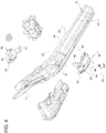
- the cross member 20 further comprises two brackets 30 defining respective rear connection points, which are arranged more at the back than the brackets 24 and are coupled to the front ends 31 of the portions 10 by means of respective connection devices 32.
- the brackets 30 laterally project outwards from the portion 22 as an extension of the portion 22 itself. This description will only discuss a single one of the devices 32, namely the one placed on the right side of the body 5, as it is similar to the one on the left side.
- the end 31 is U-shaped or omega-shaped, in a cross section view, so as to define a recess 33, which faces upwards and longitudinally extends along the longitudinal member 8.
- the end 31 comprises an approximately horizontal base wall 34 and two side walls 35, which project upwards from side edges of the base wall 34, are joined to the base wall 34 and face one another, so as to define the recess 33.
- the walls of the longitudinal member 8 at the end 31 and at the portion 11 are at least partly multi-layered, namely they consist of a main layer or wall and of at least one reinforcement layer or wall, which at least partly overlaps the main one.
- the base wall 34 has a through hole 36 with a substantially vertical axis.
- the device 32 comprises two shaped reinforcement plates 38 and 39, which are arranged on opposite sides of the base wall 34.
- the plate 38 is arranged in the recess 33, namely above the base wall 34, and is fixed to the end 31 and/or to the portion 11, preferably through welding.
- the plate 38 has wings which overlap and are welded to both the base wall 34 and the walls 35.
- the plate 38 comprises at least one wing 41, which rests against and is welded to the end 31, and a wall 42, which is joined to the wing 41, is vertically spaced apart from the base wall 34 and faces the latter.
- the wall 42 has an opening 44, which is axially aligned with the hole 36.
- the opening 44 has a greater width than the hole 36 and, for example, has a longitudinally oblong peripheral edge 45 so as to form a slot. More preferably, the edge 45 has a curved portion 46, which is vertically aligned with the hole 36.
- the plate 39 is arranged under the base wall 34, rests against the latter and is fixed to the end 31 and/or to the portion 11, preferably through welding.
- the plate 39 comprises a wall 48 resting against a lower face of the base wall 34 and having a through hole 50, which is coaxial to the hole 36 and has smaller dimensions than the hole 36, so that the hole 50 is defined by an annular portion 51 of the wall 48 surrounded by the edge of the hole 36.
- the plate 39 further comprises a wall 53, which is joined to the wall 48 and rests against the portion 11.
- the plate 39 also comprises two side wings 54, which project upwards from the walls 48 and/or 53 and are joined to the latter so as to define a U-shaped cross section which is similar to the one of the longitudinal member 8.
- the wings 54 respectively rest against the outer faces of the walls 35.
- the device 32 further comprises a nut screw 55, which is coaxial to the holes 36 and 50 and is fixed relative to the end 31, but is supported by the plate 38 and/or by the plate 39 and not directly by the end 31.
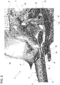
- the nut screw 55 comprises a lower end 56, which axially rests against the annular portion 51 and is preferably welded to the latter. Therefore, the lower end 56 is surrounded by the edge of the hole 36, with clearance, and the annular portion 51 is axially clamped between the nut screw 55 and the bracket 30 of the cross member 20 due to the tightening of a crew 58 ( figure 3 ), which goes through the bracket 30, engages the hole 50 and is screwed into the nut screw 55.
- the nut screw 55 is preferably welded to the plate 38, for example to the curved portion 46 of the edge 45. More preferably, the nut screw 55 comprises an upper end 60, which projects upwards relative to the wall 42 of the plate 38 and is provided with an inner thread, into which the screw 58 is screwed.
- the wall 48 comprises a weakened area 61, which is arranged in a position relatively close to the edge of the hole 50, namely is arranged in a position immediately adjacent to the annular portion 51, against which the lower end 56 of the nut screw 55 axially rests.
- the weakened area 61 is designed so as to break when a given stress threshold is exceeded.
- this breaking basically, the annular portion 51 breaks and is uncoupled from the remaining part of the plate 39.
- this breaking together with the breaking of the weld connecting the nut screw 55 to the plate 38, allows the nut screw 55 to be uncoupled from the longitudinal member 8 together with the screw 58. Therefore, in this way, the cross member 20 is released from the longitudinal member 8 in case of an accident.
- the weakened area 61 is arranged in a local manner behind the hole 50 (considering the longitudinal driving direction of the motor vehicle 1).
- the weakened area can become a virtual hinge, around which the annular portion 51 tends to bend downwards when the struts 12 and the cross member 20 are stressed during a front crash.
- the weakened area 61 is vertically aligned with at least part of the edge of the hole 36.
- the weakened area 61 comprises at least one hole 63, which has smaller dimensions that the hole 50. More in particular, the hole 63 goes through the wall 48 of the plate 39. According to variants which are not shown herein, in combination with or as an alternative to the hole 63, the weakened area 61 comprises at least one cut on the wall 48 and/or a reduction in the thickness of the wall 48. As already mentioned above, the hole 63 is longitudinally arranged behind the hole 50.
- the load transmitted by the struts 12 keeps pushing the cross member 20 downwards, thus causing it to rotate, substantially pivoting around the ends 31 and/or the weakened areas 61 (in a counterclockwise direction in figure 7 ). Due to this rotation, the cross member 20 tends to move away from the struts 9, thus freeing space for the backward and downward movement of the powertrain 4 and tends to stress the devices 32 to a greater extent until the plates 39 break in the weakened areas 61 and the weld connecting the nut screws 55 to the plates 38 breaks as well. In this way, the cross member 20 is completely uncoupled from the longitudinal members 8 and, as a consequence, can slide under the floor of the motor vehicle 1.
- the powertrain 4 is not dragged together with the cross member 20, but is released from the cross member 20 and from the longitudinal members 8 in a known manner, which is not described in detail. Following this uncoupling operation, the powertrain 4 moves depending on the intensity of the crash and depending on the spaces created in the engine compartment 3 during the plastic deformation of the body 5, regardless of the movement of the cross member 20.
- the powertrain 4 has enough space to avoid hitting the wall 7, namely to avoid particular deformations in the passenger compartment 2 and particular deceleration peaks for the occupants of the passenger compartment 2.
- the powertrain 4 moves backwards relative to its original position and simply rests against the wall 7.
- the cross member 20 independently uncouples itself from the longitudinal members 8 and moves freely, namely in an autonomous manner.
- the release is relatively simple as it does not require pyrotechnic elements, but only involves proper measures to be adopted at the devices 32 as well as at the connection members 25. Indeed, the features described above lead to simplicity advantages compared to similar bodies of the prior art.
- cross section of the struts 12 and/or of the longitudinal members 8 and/or the shape of the cross member 20 and/or the configuration of the connection members 25 could be different from the ones indicated herein by mere way of example.
Landscapes
- Engineering & Computer Science (AREA)
- Chemical & Material Sciences (AREA)
- Combustion & Propulsion (AREA)
- Transportation (AREA)
- Mechanical Engineering (AREA)
- Body Structure For Vehicles (AREA)
Priority Applications (2)
| Application Number | Priority Date | Filing Date | Title |
|---|---|---|---|
| EP19203916.2A EP3808635B1 (fr) | 2019-10-17 | 2019-10-17 | Véhicule automobile équipé d'un système de libération pour désaccoupler un élément transversal dans le compartiment moteur dans le cas d'une collision frontale |
| US17/072,132 US11472483B2 (en) | 2019-10-17 | 2020-10-16 | Motor vehicle provided with a release system for uncoupling a cross member in the engine compartment in case of a front crash |
Applications Claiming Priority (1)
| Application Number | Priority Date | Filing Date | Title |
|---|---|---|---|
| EP19203916.2A EP3808635B1 (fr) | 2019-10-17 | 2019-10-17 | Véhicule automobile équipé d'un système de libération pour désaccoupler un élément transversal dans le compartiment moteur dans le cas d'une collision frontale |
Publications (2)
| Publication Number | Publication Date |
|---|---|
| EP3808635A1 true EP3808635A1 (fr) | 2021-04-21 |
| EP3808635B1 EP3808635B1 (fr) | 2023-11-29 |
Family
ID=68886687
Family Applications (1)
| Application Number | Title | Priority Date | Filing Date |
|---|---|---|---|
| EP19203916.2A Active EP3808635B1 (fr) | 2019-10-17 | 2019-10-17 | Véhicule automobile équipé d'un système de libération pour désaccoupler un élément transversal dans le compartiment moteur dans le cas d'une collision frontale |
Country Status (2)
| Country | Link |
|---|---|
| US (1) | US11472483B2 (fr) |
| EP (1) | EP3808635B1 (fr) |
Families Citing this family (1)
| Publication number | Priority date | Publication date | Assignee | Title |
|---|---|---|---|---|
| KR20240040481A (ko) * | 2022-09-21 | 2024-03-28 | 현대자동차주식회사 | 차량용 프레임 구조 |
Citations (7)
| Publication number | Priority date | Publication date | Assignee | Title |
|---|---|---|---|---|
| US6109654A (en) * | 1997-12-12 | 2000-08-29 | Honda Giken Kogyo Kabushiki Kaisha | Shock absorpting vehicle body structure |
| EP1361099A2 (fr) | 2002-05-10 | 2003-11-12 | Nissan Motor Company, Limited | Dispositif de support d'arbre d'entraínement |
| EP1510444A1 (fr) * | 2003-08-25 | 2005-03-02 | Ford Global Technologies, LLC, A subsidary of Ford Motor Company | Châssis auxiliaire d'un véhicule automobile avec sécurité élevée en cas d'accident |
| US20110198889A1 (en) * | 2010-02-15 | 2011-08-18 | Mazda Motor Corporation | Lower structure of automotive vehicle |
| US20140203543A1 (en) * | 2013-01-21 | 2014-07-24 | Toyota Jidosha Kabushiki Kaisha | Vehicle structure |
| EP2810854A1 (fr) | 2013-06-07 | 2014-12-10 | Fiat Group Automobiles S.p.A. | Véhicule automobile équipé d'un système de libération pour désaccoupler un élément transversal dans le compartiment moteur dans le cas d'une collision frontale |
| US20150274210A1 (en) * | 2012-12-14 | 2015-10-01 | Bayerische Motoren Werke Aktiengesellschaft | Motor Vehicle Having an Axle Support |
Family Cites Families (2)
| Publication number | Priority date | Publication date | Assignee | Title |
|---|---|---|---|---|
| JP5488117B2 (ja) * | 2010-03-30 | 2014-05-14 | マツダ株式会社 | 自動車の駆動力伝達装置およびこれを備えた自動車の下部車体構造 |
| US9616931B2 (en) * | 2015-09-16 | 2017-04-11 | GM Global Technology Operations LLC | Releasable cradle to body joint |
-
2019
- 2019-10-17 EP EP19203916.2A patent/EP3808635B1/fr active Active
-
2020
- 2020-10-16 US US17/072,132 patent/US11472483B2/en active Active
Patent Citations (7)
| Publication number | Priority date | Publication date | Assignee | Title |
|---|---|---|---|---|
| US6109654A (en) * | 1997-12-12 | 2000-08-29 | Honda Giken Kogyo Kabushiki Kaisha | Shock absorpting vehicle body structure |
| EP1361099A2 (fr) | 2002-05-10 | 2003-11-12 | Nissan Motor Company, Limited | Dispositif de support d'arbre d'entraínement |
| EP1510444A1 (fr) * | 2003-08-25 | 2005-03-02 | Ford Global Technologies, LLC, A subsidary of Ford Motor Company | Châssis auxiliaire d'un véhicule automobile avec sécurité élevée en cas d'accident |
| US20110198889A1 (en) * | 2010-02-15 | 2011-08-18 | Mazda Motor Corporation | Lower structure of automotive vehicle |
| US20150274210A1 (en) * | 2012-12-14 | 2015-10-01 | Bayerische Motoren Werke Aktiengesellschaft | Motor Vehicle Having an Axle Support |
| US20140203543A1 (en) * | 2013-01-21 | 2014-07-24 | Toyota Jidosha Kabushiki Kaisha | Vehicle structure |
| EP2810854A1 (fr) | 2013-06-07 | 2014-12-10 | Fiat Group Automobiles S.p.A. | Véhicule automobile équipé d'un système de libération pour désaccoupler un élément transversal dans le compartiment moteur dans le cas d'une collision frontale |
Also Published As
| Publication number | Publication date |
|---|---|
| EP3808635B1 (fr) | 2023-11-29 |
| US20210114667A1 (en) | 2021-04-22 |
| US11472483B2 (en) | 2022-10-18 |
Similar Documents
| Publication | Publication Date | Title |
|---|---|---|
| US10882557B2 (en) | Vehicle lower structure | |
| CN107054470B (zh) | 车身前部构造 | |
| US8419116B2 (en) | Vehicle frame assembly | |
| EP2927097B1 (fr) | Véhicule automobile pourvu d'un groupe motopropulseur et dispositif de sécurité pour déplacer un tel groupe latéralement lors d'une collision | |
| US10940892B2 (en) | Vehicle substructure | |
| CN109421805B (zh) | 电动车辆的车体构造 | |
| CN204688218U (zh) | 用于车辆的底盘组件和用于车辆的副车架 | |
| JP5874599B2 (ja) | フロントサブフレーム構造およびフロントサブフレームの組付け方法 | |
| US20100026047A1 (en) | Sequential Crash Hinges in Automotive Frame Rails | |
| JP6801601B2 (ja) | 車両前部構造 | |
| WO2012063393A1 (fr) | Structure de plancher d'automobile | |
| JP2018140711A (ja) | 電気自動車のフロア構造 | |
| EP3782858B1 (fr) | Véhicule automobile avec un agencement de fixation d'un longeron et d'une boîte d'écrasement | |
| JP2020032738A (ja) | 車両下部構造 | |
| EP2894083B1 (fr) | Structure de partie inférieure d'un véhicule | |
| US10647276B2 (en) | Vehicle body structure | |
| CN112406761B (zh) | 将保险杠梁联接至车辆的冲撞盒和侧轨的安装装置 | |
| JP6787371B2 (ja) | 車両の下部構造 | |
| US11472483B2 (en) | Motor vehicle provided with a release system for uncoupling a cross member in the engine compartment in case of a front crash | |
| JP2013241052A (ja) | 自動車の車体フレーム構造 | |
| US11787476B2 (en) | Motor vehicle provided with a release system to detach a crossbar in the engine compartment in the event of a frontal collision | |
| JP2005022598A (ja) | バンパ装置 | |
| JP2019123272A (ja) | 車両下部構造 | |
| JP5513904B2 (ja) | 車両の前部車体構造 | |
| CN107635859B (zh) | 用于保留副车架的后区段的副车架方法和结构 |
Legal Events
| Date | Code | Title | Description |
|---|---|---|---|
| PUAI | Public reference made under article 153(3) epc to a published international application that has entered the european phase |
Free format text: ORIGINAL CODE: 0009012 |
|
| STAA | Information on the status of an ep patent application or granted ep patent |
Free format text: STATUS: THE APPLICATION HAS BEEN PUBLISHED |
|
| AK | Designated contracting states |
Kind code of ref document: A1 Designated state(s): AL AT BE BG CH CY CZ DE DK EE ES FI FR GB GR HR HU IE IS IT LI LT LU LV MC MK MT NL NO PL PT RO RS SE SI SK SM TR |
|
| AX | Request for extension of the european patent |
Extension state: BA ME |
|
| STAA | Information on the status of an ep patent application or granted ep patent |
Free format text: STATUS: REQUEST FOR EXAMINATION WAS MADE |
|
| 17P | Request for examination filed |
Effective date: 20210826 |
|
| RBV | Designated contracting states (corrected) |
Designated state(s): AL AT BE BG CH CY CZ DE DK EE ES FI FR GB GR HR HU IE IS IT LI LT LU LV MC MK MT NL NO PL PT RO RS SE SI SK SM TR |
|
| GRAP | Despatch of communication of intention to grant a patent |
Free format text: ORIGINAL CODE: EPIDOSNIGR1 |
|
| STAA | Information on the status of an ep patent application or granted ep patent |
Free format text: STATUS: GRANT OF PATENT IS INTENDED |
|
| INTG | Intention to grant announced |
Effective date: 20230522 |
|
| GRAS | Grant fee paid |
Free format text: ORIGINAL CODE: EPIDOSNIGR3 |
|
| RAP3 | Party data changed (applicant data changed or rights of an application transferred) |
Owner name: TOFAS TURK OTOMOBIL FABRIKASI ANONIM SIRKETI Owner name: STELLANTIS EUROPE S.P.A. |
|
| GRAA | (expected) grant |
Free format text: ORIGINAL CODE: 0009210 |
|
| STAA | Information on the status of an ep patent application or granted ep patent |
Free format text: STATUS: THE PATENT HAS BEEN GRANTED |
|
| AK | Designated contracting states |
Kind code of ref document: B1 Designated state(s): AL AT BE BG CH CY CZ DE DK EE ES FI FR GB GR HR HU IE IS IT LI LT LU LV MC MK MT NL NO PL PT RO RS SE SI SK SM TR |
|
| REG | Reference to a national code |
Ref country code: GB Ref legal event code: FG4D |
|
| REG | Reference to a national code |
Ref country code: CH Ref legal event code: EP |
|
| REG | Reference to a national code |
Ref country code: DE Ref legal event code: R096 Ref document number: 602019042256 Country of ref document: DE |
|
| REG | Reference to a national code |
Ref country code: IE Ref legal event code: FG4D |
|
| REG | Reference to a national code |
Ref country code: LT Ref legal event code: MG9D |
|
| REG | Reference to a national code |
Ref country code: NL Ref legal event code: MP Effective date: 20231129 |
|
| PG25 | Lapsed in a contracting state [announced via postgrant information from national office to epo] |
Ref country code: GR Free format text: LAPSE BECAUSE OF FAILURE TO SUBMIT A TRANSLATION OF THE DESCRIPTION OR TO PAY THE FEE WITHIN THE PRESCRIBED TIME-LIMIT Effective date: 20240301 |
|
| PG25 | Lapsed in a contracting state [announced via postgrant information from national office to epo] |
Ref country code: IS Free format text: LAPSE BECAUSE OF FAILURE TO SUBMIT A TRANSLATION OF THE DESCRIPTION OR TO PAY THE FEE WITHIN THE PRESCRIBED TIME-LIMIT Effective date: 20240329 |
|
| PG25 | Lapsed in a contracting state [announced via postgrant information from national office to epo] |
Ref country code: LT Free format text: LAPSE BECAUSE OF FAILURE TO SUBMIT A TRANSLATION OF THE DESCRIPTION OR TO PAY THE FEE WITHIN THE PRESCRIBED TIME-LIMIT Effective date: 20231129 |
|
| PG25 | Lapsed in a contracting state [announced via postgrant information from national office to epo] |
Ref country code: ES Free format text: LAPSE BECAUSE OF FAILURE TO SUBMIT A TRANSLATION OF THE DESCRIPTION OR TO PAY THE FEE WITHIN THE PRESCRIBED TIME-LIMIT Effective date: 20231129 |
|
| PG25 | Lapsed in a contracting state [announced via postgrant information from national office to epo] |
Ref country code: LT Free format text: LAPSE BECAUSE OF FAILURE TO SUBMIT A TRANSLATION OF THE DESCRIPTION OR TO PAY THE FEE WITHIN THE PRESCRIBED TIME-LIMIT Effective date: 20231129 Ref country code: IS Free format text: LAPSE BECAUSE OF FAILURE TO SUBMIT A TRANSLATION OF THE DESCRIPTION OR TO PAY THE FEE WITHIN THE PRESCRIBED TIME-LIMIT Effective date: 20240329 Ref country code: GR Free format text: LAPSE BECAUSE OF FAILURE TO SUBMIT A TRANSLATION OF THE DESCRIPTION OR TO PAY THE FEE WITHIN THE PRESCRIBED TIME-LIMIT Effective date: 20240301 Ref country code: ES Free format text: LAPSE BECAUSE OF FAILURE TO SUBMIT A TRANSLATION OF THE DESCRIPTION OR TO PAY THE FEE WITHIN THE PRESCRIBED TIME-LIMIT Effective date: 20231129 Ref country code: BG Free format text: LAPSE BECAUSE OF FAILURE TO SUBMIT A TRANSLATION OF THE DESCRIPTION OR TO PAY THE FEE WITHIN THE PRESCRIBED TIME-LIMIT Effective date: 20240229 |
|
| REG | Reference to a national code |
Ref country code: AT Ref legal event code: MK05 Ref document number: 1635853 Country of ref document: AT Kind code of ref document: T Effective date: 20231129 |
|
| PG25 | Lapsed in a contracting state [announced via postgrant information from national office to epo] |
Ref country code: NL Free format text: LAPSE BECAUSE OF FAILURE TO SUBMIT A TRANSLATION OF THE DESCRIPTION OR TO PAY THE FEE WITHIN THE PRESCRIBED TIME-LIMIT Effective date: 20231129 |
|
| PG25 | Lapsed in a contracting state [announced via postgrant information from national office to epo] |
Ref country code: SE Free format text: LAPSE BECAUSE OF FAILURE TO SUBMIT A TRANSLATION OF THE DESCRIPTION OR TO PAY THE FEE WITHIN THE PRESCRIBED TIME-LIMIT Effective date: 20231129 Ref country code: RS Free format text: LAPSE BECAUSE OF FAILURE TO SUBMIT A TRANSLATION OF THE DESCRIPTION OR TO PAY THE FEE WITHIN THE PRESCRIBED TIME-LIMIT Effective date: 20231129 Ref country code: PL Free format text: LAPSE BECAUSE OF FAILURE TO SUBMIT A TRANSLATION OF THE DESCRIPTION OR TO PAY THE FEE WITHIN THE PRESCRIBED TIME-LIMIT Effective date: 20231129 Ref country code: NO Free format text: LAPSE BECAUSE OF FAILURE TO SUBMIT A TRANSLATION OF THE DESCRIPTION OR TO PAY THE FEE WITHIN THE PRESCRIBED TIME-LIMIT Effective date: 20240229 Ref country code: NL Free format text: LAPSE BECAUSE OF FAILURE TO SUBMIT A TRANSLATION OF THE DESCRIPTION OR TO PAY THE FEE WITHIN THE PRESCRIBED TIME-LIMIT Effective date: 20231129 Ref country code: LV Free format text: LAPSE BECAUSE OF FAILURE TO SUBMIT A TRANSLATION OF THE DESCRIPTION OR TO PAY THE FEE WITHIN THE PRESCRIBED TIME-LIMIT Effective date: 20231129 Ref country code: HR Free format text: LAPSE BECAUSE OF FAILURE TO SUBMIT A TRANSLATION OF THE DESCRIPTION OR TO PAY THE FEE WITHIN THE PRESCRIBED TIME-LIMIT Effective date: 20231129 |
|
| PG25 | Lapsed in a contracting state [announced via postgrant information from national office to epo] |
Ref country code: DK Free format text: LAPSE BECAUSE OF FAILURE TO SUBMIT A TRANSLATION OF THE DESCRIPTION OR TO PAY THE FEE WITHIN THE PRESCRIBED TIME-LIMIT Effective date: 20231129 |
|
| PG25 | Lapsed in a contracting state [announced via postgrant information from national office to epo] |
Ref country code: CZ Free format text: LAPSE BECAUSE OF FAILURE TO SUBMIT A TRANSLATION OF THE DESCRIPTION OR TO PAY THE FEE WITHIN THE PRESCRIBED TIME-LIMIT Effective date: 20231129 Ref country code: AT Free format text: LAPSE BECAUSE OF FAILURE TO SUBMIT A TRANSLATION OF THE DESCRIPTION OR TO PAY THE FEE WITHIN THE PRESCRIBED TIME-LIMIT Effective date: 20231129 |
|
| PG25 | Lapsed in a contracting state [announced via postgrant information from national office to epo] |
Ref country code: SK Free format text: LAPSE BECAUSE OF FAILURE TO SUBMIT A TRANSLATION OF THE DESCRIPTION OR TO PAY THE FEE WITHIN THE PRESCRIBED TIME-LIMIT Effective date: 20231129 |
|
| PG25 | Lapsed in a contracting state [announced via postgrant information from national office to epo] |
Ref country code: SM Free format text: LAPSE BECAUSE OF FAILURE TO SUBMIT A TRANSLATION OF THE DESCRIPTION OR TO PAY THE FEE WITHIN THE PRESCRIBED TIME-LIMIT Effective date: 20231129 Ref country code: SK Free format text: LAPSE BECAUSE OF FAILURE TO SUBMIT A TRANSLATION OF THE DESCRIPTION OR TO PAY THE FEE WITHIN THE PRESCRIBED TIME-LIMIT Effective date: 20231129 Ref country code: RO Free format text: LAPSE BECAUSE OF FAILURE TO SUBMIT A TRANSLATION OF THE DESCRIPTION OR TO PAY THE FEE WITHIN THE PRESCRIBED TIME-LIMIT Effective date: 20231129 Ref country code: EE Free format text: LAPSE BECAUSE OF FAILURE TO SUBMIT A TRANSLATION OF THE DESCRIPTION OR TO PAY THE FEE WITHIN THE PRESCRIBED TIME-LIMIT Effective date: 20231129 Ref country code: DK Free format text: LAPSE BECAUSE OF FAILURE TO SUBMIT A TRANSLATION OF THE DESCRIPTION OR TO PAY THE FEE WITHIN THE PRESCRIBED TIME-LIMIT Effective date: 20231129 Ref country code: CZ Free format text: LAPSE BECAUSE OF FAILURE TO SUBMIT A TRANSLATION OF THE DESCRIPTION OR TO PAY THE FEE WITHIN THE PRESCRIBED TIME-LIMIT Effective date: 20231129 Ref country code: AT Free format text: LAPSE BECAUSE OF FAILURE TO SUBMIT A TRANSLATION OF THE DESCRIPTION OR TO PAY THE FEE WITHIN THE PRESCRIBED TIME-LIMIT Effective date: 20231129 |
|
| PG25 | Lapsed in a contracting state [announced via postgrant information from national office to epo] |
Ref country code: PT Free format text: LAPSE BECAUSE OF FAILURE TO SUBMIT A TRANSLATION OF THE DESCRIPTION OR TO PAY THE FEE WITHIN THE PRESCRIBED TIME-LIMIT Effective date: 20240401 |
|
| PG25 | Lapsed in a contracting state [announced via postgrant information from national office to epo] |
Ref country code: PT Free format text: LAPSE BECAUSE OF FAILURE TO SUBMIT A TRANSLATION OF THE DESCRIPTION OR TO PAY THE FEE WITHIN THE PRESCRIBED TIME-LIMIT Effective date: 20240401 |
|
| REG | Reference to a national code |
Ref country code: DE Ref legal event code: R097 Ref document number: 602019042256 Country of ref document: DE |
|
| PLBE | No opposition filed within time limit |
Free format text: ORIGINAL CODE: 0009261 |
|
| STAA | Information on the status of an ep patent application or granted ep patent |
Free format text: STATUS: NO OPPOSITION FILED WITHIN TIME LIMIT |
|
| PG25 | Lapsed in a contracting state [announced via postgrant information from national office to epo] |
Ref country code: SI Free format text: LAPSE BECAUSE OF FAILURE TO SUBMIT A TRANSLATION OF THE DESCRIPTION OR TO PAY THE FEE WITHIN THE PRESCRIBED TIME-LIMIT Effective date: 20231129 |
|
| PG25 | Lapsed in a contracting state [announced via postgrant information from national office to epo] |
Ref country code: SI Free format text: LAPSE BECAUSE OF FAILURE TO SUBMIT A TRANSLATION OF THE DESCRIPTION OR TO PAY THE FEE WITHIN THE PRESCRIBED TIME-LIMIT Effective date: 20231129 |
|
| 26N | No opposition filed |
Effective date: 20240830 |
|
| REG | Reference to a national code |
Ref country code: CH Ref legal event code: PL |
|
| GBPC | Gb: european patent ceased through non-payment of renewal fee |
Effective date: 20241017 |
|
| PG25 | Lapsed in a contracting state [announced via postgrant information from national office to epo] |
Ref country code: MC Free format text: LAPSE BECAUSE OF FAILURE TO SUBMIT A TRANSLATION OF THE DESCRIPTION OR TO PAY THE FEE WITHIN THE PRESCRIBED TIME-LIMIT Effective date: 20231129 |
|
| PG25 | Lapsed in a contracting state [announced via postgrant information from national office to epo] |
Ref country code: GB Free format text: LAPSE BECAUSE OF NON-PAYMENT OF DUE FEES Effective date: 20241017 |
|
| PG25 | Lapsed in a contracting state [announced via postgrant information from national office to epo] |
Ref country code: BE Free format text: LAPSE BECAUSE OF NON-PAYMENT OF DUE FEES Effective date: 20241031 Ref country code: LU Free format text: LAPSE BECAUSE OF NON-PAYMENT OF DUE FEES Effective date: 20241017 |
|
| PG25 | Lapsed in a contracting state [announced via postgrant information from national office to epo] |
Ref country code: CH Free format text: LAPSE BECAUSE OF NON-PAYMENT OF DUE FEES Effective date: 20241031 |
|
| REG | Reference to a national code |
Ref country code: BE Ref legal event code: MM Effective date: 20241031 |
|
| PG25 | Lapsed in a contracting state [announced via postgrant information from national office to epo] |
Ref country code: FI Free format text: LAPSE BECAUSE OF FAILURE TO SUBMIT A TRANSLATION OF THE DESCRIPTION OR TO PAY THE FEE WITHIN THE PRESCRIBED TIME-LIMIT Effective date: 20231129 |
|
| PGFP | Annual fee paid to national office [announced via postgrant information from national office to epo] |
Ref country code: IT Payment date: 20250923 Year of fee payment: 7 |
|
| PGFP | Annual fee paid to national office [announced via postgrant information from national office to epo] |
Ref country code: FR Payment date: 20250924 Year of fee payment: 7 |
|
| PG25 | Lapsed in a contracting state [announced via postgrant information from national office to epo] |
Ref country code: IE Free format text: LAPSE BECAUSE OF NON-PAYMENT OF DUE FEES Effective date: 20241017 |
|
| PGFP | Annual fee paid to national office [announced via postgrant information from national office to epo] |
Ref country code: DE Payment date: 20250923 Year of fee payment: 7 |
|
| PG25 | Lapsed in a contracting state [announced via postgrant information from national office to epo] |
Ref country code: CY Free format text: LAPSE BECAUSE OF FAILURE TO SUBMIT A TRANSLATION OF THE DESCRIPTION OR TO PAY THE FEE WITHIN THE PRESCRIBED TIME-LIMIT; INVALID AB INITIO Effective date: 20191017 |
|
| PG25 | Lapsed in a contracting state [announced via postgrant information from national office to epo] |
Ref country code: HU Free format text: LAPSE BECAUSE OF FAILURE TO SUBMIT A TRANSLATION OF THE DESCRIPTION OR TO PAY THE FEE WITHIN THE PRESCRIBED TIME-LIMIT; INVALID AB INITIO Effective date: 20191017 |