EP3808687A1 - Système de surveillance de l'état d'un convoyeur et convoyeur avec système de surveillance - Google Patents
Système de surveillance de l'état d'un convoyeur et convoyeur avec système de surveillance Download PDFInfo
- Publication number
- EP3808687A1 EP3808687A1 EP19203228.2A EP19203228A EP3808687A1 EP 3808687 A1 EP3808687 A1 EP 3808687A1 EP 19203228 A EP19203228 A EP 19203228A EP 3808687 A1 EP3808687 A1 EP 3808687A1
- Authority
- EP
- European Patent Office
- Prior art keywords
- images
- conveyor
- conveyor system
- transport device
- conveyor line
- Prior art date
- Legal status (The legal status is an assumption and is not a legal conclusion. Google has not performed a legal analysis and makes no representation as to the accuracy of the status listed.)
- Withdrawn
Links
- 238000000034 method Methods 0.000 title claims description 19
- 238000012544 monitoring process Methods 0.000 title claims description 13
- 230000008859 change Effects 0.000 claims abstract description 22
- 238000004458 analytical method Methods 0.000 claims abstract description 14
- 230000005855 radiation Effects 0.000 claims description 8
- 230000003287 optical effect Effects 0.000 claims description 5
- 238000001454 recorded image Methods 0.000 claims description 5
- 230000033001 locomotion Effects 0.000 claims description 2
- 230000032258 transport Effects 0.000 description 71
- 238000012423 maintenance Methods 0.000 description 13
- 238000005259 measurement Methods 0.000 description 6
- 238000007689 inspection Methods 0.000 description 5
- 230000000007 visual effect Effects 0.000 description 5
- 230000009056 active transport Effects 0.000 description 4
- 238000001514 detection method Methods 0.000 description 4
- 238000009434 installation Methods 0.000 description 4
- 230000009057 passive transport Effects 0.000 description 4
- 230000001960 triggered effect Effects 0.000 description 3
- 230000008901 benefit Effects 0.000 description 2
- 238000011156 evaluation Methods 0.000 description 2
- 238000003384 imaging method Methods 0.000 description 2
- 230000005856 abnormality Effects 0.000 description 1
- 230000009471 action Effects 0.000 description 1
- 230000005540 biological transmission Effects 0.000 description 1
- 230000015556 catabolic process Effects 0.000 description 1
- 238000012790 confirmation Methods 0.000 description 1
- 230000001934 delay Effects 0.000 description 1
- 238000006073 displacement reaction Methods 0.000 description 1
- 230000007613 environmental effect Effects 0.000 description 1
- 230000010006 flight Effects 0.000 description 1
- 238000010191 image analysis Methods 0.000 description 1
- 208000018910 keratinopathic ichthyosis Diseases 0.000 description 1
- 230000010355 oscillation Effects 0.000 description 1
- 238000012805 post-processing Methods 0.000 description 1
- 230000008569 process Effects 0.000 description 1
- 238000012545 processing Methods 0.000 description 1
- 230000000717 retained effect Effects 0.000 description 1
- 230000001953 sensory effect Effects 0.000 description 1
- 239000000779 smoke Substances 0.000 description 1
- 239000000725 suspension Substances 0.000 description 1
- 238000012549 training Methods 0.000 description 1
- 230000007704 transition Effects 0.000 description 1
- 238000012795 verification Methods 0.000 description 1
- 230000003442 weekly effect Effects 0.000 description 1
Images
Classifications
-
- B—PERFORMING OPERATIONS; TRANSPORTING
- B65—CONVEYING; PACKING; STORING; HANDLING THIN OR FILAMENTARY MATERIAL
- B65G—TRANSPORT OR STORAGE DEVICES, e.g. CONVEYORS FOR LOADING OR TIPPING, SHOP CONVEYOR SYSTEMS OR PNEUMATIC TUBE CONVEYORS
- B65G43/00—Control devices, e.g. for safety, warning or fault-correcting
- B65G43/02—Control devices, e.g. for safety, warning or fault-correcting detecting dangerous physical condition of load carriers, e.g. for interrupting the drive in the event of overheating
-
- B—PERFORMING OPERATIONS; TRANSPORTING
- B65—CONVEYING; PACKING; STORING; HANDLING THIN OR FILAMENTARY MATERIAL
- B65G—TRANSPORT OR STORAGE DEVICES, e.g. CONVEYORS FOR LOADING OR TIPPING, SHOP CONVEYOR SYSTEMS OR PNEUMATIC TUBE CONVEYORS
- B65G2203/00—Indexing code relating to control or detection of the articles or the load carriers during conveying
- B65G2203/02—Control or detection
- B65G2203/0266—Control or detection relating to the load carrier(s)
- B65G2203/0275—Damage on the load carrier
-
- B—PERFORMING OPERATIONS; TRANSPORTING
- B65—CONVEYING; PACKING; STORING; HANDLING THIN OR FILAMENTARY MATERIAL
- B65G—TRANSPORT OR STORAGE DEVICES, e.g. CONVEYORS FOR LOADING OR TIPPING, SHOP CONVEYOR SYSTEMS OR PNEUMATIC TUBE CONVEYORS
- B65G2203/00—Indexing code relating to control or detection of the articles or the load carriers during conveying
- B65G2203/04—Detection means
- B65G2203/041—Camera
Definitions
- the present invention relates to a method for condition monitoring when operating a conveyor system and to a conveyor system with wear detection according to the independent claims.
- the present invention relates in particular to the technical field of conveyor systems within an airport for pieces of luggage and general cargo.
- One of the goals of every airport operator is to reduce breakdowns in baggage handling to a minimum. In practice, this means that the baggage conveyor systems are kept “alive” during operation and time-based maintenance is carried out outside of operating hours.
- Airport baggage handling systems must be able to sort and transport several thousand pieces of baggage per hour quickly and with great reliability.
- DCV systems Direction Coded Vehicles
- DCV systems Direct Coded Vehicles
- Potential system problems can be identified by the visual condition of the components, misalignment or debris, or unexpected objects such as lost luggage or tools left behind during maintenance.
- Performing system visits for the physical inspection and verification of components is extremely resource-intensive due to the length of the system in a DCV system and its effectiveness depends to a large extent on the skills, training, care and personal judgment of individual employees.
- the system environment for such surveys, especially in DCV tunnels is often difficult and dangerous, which reduces the frequency with which system inspections are carried out.
- the system inspections are not carried out often enough to identify existing problems.
- a well-trained human employee overlooks things (for example a slowly loosening screw) or interprets them incorrectly, so that system inspections are not sufficient to prevent system failures.
- the present invention is therefore based on the object of enabling fast, reliable and regular status monitoring in conveyor systems, in particular baggage conveyor systems, and more particularly in DCV systems.
- occurring maintenance problems can be identified at an early stage and operational resources can be used to rectify and maintain problems and failures are directed to failures rather than firefighting.
- This object is achieved by the solutions described in the independent claims.
- the availability of this solution as a retrofit simplifies installation and maintenance compared to stationary installations, especially due to the length of the system.
- the method is suitable for all conveyor systems, but is particularly well suited for airport baggage conveyor systems in which, due to their length, stationary installations mean a great deal of installation and expense.
- An existing conveyor system simply has to be additionally equipped with a measuring transport device and have a background system adapted for analyzing the images, with either an existing background system of the conveyor system being adapted for this purpose or a background system specially provided for this being able to be used.
- a transport device should be understood to mean any active or passive conveying unit. This includes both means of transport for active transport (e.g. a driverless transport vehicle) that drive their conveyor line automatically, under their own power, as well as transport aids for passive transport (e.g. transport trays) that lie on a conveyor line from this, typically via belts and / or rollers , are driven.
- active transport e.g. a driverless transport vehicle
- passive transport e.g. transport trays
- the background system can be arranged on the measuring transport device or in a stationary manner; in the case of a stationary arrangement, wireless information transmission is possible.
- An arrangement on the measurement vehicle has the advantage that smaller amounts of data (only those images that are used to determine a change in status and that lead to a message) have to be transmitted.
- the measuring transport device can be designed as a normal transport device plus image display device or as a special measuring transport device with additional functionality (eg background system or the like).
- the image is recorded from the perspective of the measuring transport device, so that the positioning of the image display device is decisive.
- a location stamp comprises the positioning and thus the perspective of the image display device, so that images with the same location stamp always deliver the same viewing angle from the same position regardless of the time of the recording.
- the location stamp is obtained from any location information of the transport device that may already be present.
- the location information is typically routinely transmitted to a higher-level background system.
- the images can be recorded at defined positions of the conveyor system, for example specified by a grid and / or orientation points of the conveyor line, so that two or more images with an identical location stamp are created over time. This choice can be combined in order to achieve a good compromise between analysis effort and sufficiently frequent condition monitoring.
- Positioning, accuracy and viewing angle of the camera are matched to the corresponding conveyor system.
- the conveyor system can be covered without the need for the covered conveyor system to overlap too much on the images.
- the image can image thermal radiation and / or optical radiation.
- the images with the same location stamp can be analyzed with regard to deviations in the physical position of the imaged parts and / or temperature and / or missing parts.
- the measuring transport device can capture at least one camera for recording the images, the camera being arranged and fastened on a transport device and being transported on this along the conveyor route.
- the camera acts as an imaging device.
- the images identified in method step c) as change in status of the conveyor system can be used together with the images identified Changes in state can be made available to a human operator for further decision-making.
- the transport device can be designed as a Destination Coded Vehicle (DCV) or as a driverless transport vehicle (FTF - Automated Guided Vehicle, AGV).
- DCV Destination Coded Vehicle
- FFF Driverless transport vehicle
- the images can be recorded at defined positions of the conveyor system, for example specified by a grid and / or orientation points of the conveyor line, so that two or more images with identical location stamps are present over time.
- the measuring transport device can be designed to record images that image thermal radiation and / or optical radiation.
- the background system can be designed to analyze the images with the same location stamp with regard to deviations in the physical position of the imaged parts and / or temperature and / or missing parts.
- the measuring transport device can comprise at least one camera for recording the images, the camera being arranged and fastened on a transport device and being transportable on this along the conveying path.
- the height and lens of the camera are matched to the conveyor system and the camera can be aligned in all directions.
- the images recognized as a change in the state of the conveyor system can be made accessible to a human operator for further decision-making, together with the recognized change in state.
- the conveyor system can be an individual carrier system (ICS), for example an airport baggage conveyor system.
- ICS individual carrier system
- the conveyor system is adapted for transport devices such as Destination Coded Vehicles (DCV) or driverless transport vehicles (FTF - Automated Guided Vehicle, AGV).
- DCV Destination Coded Vehicles
- FFF Driverless transport vehicles
- the background system can be arranged on the measuring transport device and can be transported along the conveyor line.
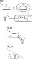
- Figure 1 shows an airport baggage handling system 2 according to an embodiment of the invention. Luggage items are moved along a conveying path 4 on transport devices 8 configured as containers 8 or differently.
- a transport device 8 designed as a measuring transport device 8m comprises detectors 10 for recording images 12 of the airport baggage handling system 2, the positioning of the measuring transport device 8m on the conveyor line 4 and the positioning of the detector 10 on the measuring transport device 8m, field of view and Resolution of the detector 10 define a location stamp 16 assigned to each image 12.
- At least one further detection device is arranged on the measuring transport device 8m and encompassed by the conveyor system.
- the further detection device detects, for example, oscillations and / or vibrations and / or temperature and / or smoke (non-exhaustive list) and sends the measured values to the background system 6, which analyzes the measured values and signals changes and / or abnormalities with a message.
- the background system 6 can also receive further measured values from stationary detection devices or otherwise.
- the transport devices 8 are active transport units 8 (and thus transport means 8 for active transport, e.g. AGV) or passive transport units 8 (and thus transport aids / conveying aids 8 for passive transport, e.g. transport trays without their own drive).
- Active conveyor units 8 have a motor or some other drive and travel on their conveyor line 4 automatically, which means that the conveyor line 4 itself is quite inexpensive and uncomplicated becomes realizable and is easy to maintain.
- Passive conveyor units 8 are driven by the conveyor line 4 itself, typically via belts and / or rollers, and therefore require a more complex route, but have much cheaper containers (mostly simple plastic tubs).
- the transport devices 8 comprise an active or passive load suspension device.
- the conveyor system 2 is adapted for transport devices 8 such as Destination Coded Vehicles (DCV) or automated guided vehicles (AGV).
- the conveyor system 2 is designed as an individual conveyor system.
- the conveyor line 4 can be completely or at least partially overlapping the same for all transport devices 8, 8m of the system (for example, in the case of a conveyor belt and passive transport devices 8) or different transport devices 8, 8m have individual, only very little or not at all overlapping conveyor lines 4 on the Conveyance level of the conveyor system 2 (for example, with active transport devices 8).
- Images 12 with the same location stamp 16 are therefore always recorded from the same perspective with an identical viewing angle.
- a time stamp t is also assigned to each recorded image 12.
- images 12, 12 'with identical location stamps 16 and time stamps t, t' that differ from one another can be used to analyze changes in the status of airport baggage handling system 2.
- the location stamp 16 can be obtained from location information of the transport device 8 that is typically already recorded in an airport baggage conveyor system 2 (in the case of direction coded vehicles, the location information is usually transmitted regularly to a background system 6 anyway).
- the measuring transport device 8m is designed as a conventional transport device 8 plus image display device (camera) 10 or as a special measuring transport device 8m with additional functionality.
- An analysis of the images 12, 12 ′ with identical location stamps 16 is carried out by a background system 6.
- the background system 6 is either at least partially arranged on the measuring transport device 8m, so that only the result of the analysis has to be transmitted, or the images 12, 12 'are transmitted to a stationary background system 6 and analyzed there.
- data are preferably transmitted wirelessly.
- Their time stamps t, t 'and their location stamps 16, 16' are transmitted together with the images 12, 12 '.
- the analysis determines a change in the state of the images 12, 12 ', with changes in the state of the conveyor system 2 itself (loosening screw, changed temperature of areas / parts of the conveyor system 2 and signs of wear and tear that can be identified as a result and / or otherwise, ...) and / or also abandoned or forgotten items (items of luggage and / or transport devices 8, 8m that have fallen from the conveyor line 4, broken and fallen parts of the conveyor system 2, forgotten maintenance items such as screwdrivers or the like, ).
- the background system detects a change in status between images 12, 12 'with the same location stamp 16 and time stamps t, t' that differ from one another, this is signaled with a message and transmitted to a computer 18, which can be included in the background system 6, so that a human assessment of this change of state can take place and determines the urgency of the maintenance of this change of state can be. With an appropriate configuration of the background system 6, this assessment can also be carried out automatically.
- Figure 2a shows a stationary status monitoring in which an observer 10 or detector 10 (human and / or machine) monitors the conveyor line 4 and the conveyor system 2 from a perspective that does not move with the transport device 8.
- the transport device 8 moves past the detector 10, so that in particular the state of the transport device 8 and of the small part of the conveyor line 4 which is in the field of view of the detector 10 is monitored.
- the detector 10 In order to image the entire conveying path 4, the detector 10 must move along the conveying path 4.
- the container fleet is monitored in a stationary manner, the observer 10 checking the containers 8 driving past.
- the positions at which images 12 are recorded are determined in a manner adapted to the respective conveyor system 2.
- the positions can be determined at regular intervals according to a grid - with another image 12 being recorded when the measuring transport device 8m passes again at the same point and with the same perspective (corresponds to the same location stamp 16).
- the spacing of the grid points is determined in a manner adapted to the imaging accuracy of the images 12 and their field of view.
- Figure 2b shows a condition monitoring system according to the invention that moves with it, in which the detector 10 moves together with the measuring transport device 8m.
- the measuring transport device 8m differs from the normal transport device 8 at least in that the measuring transport device 8m has a detector (image creation device) 10.
- the detector 10 moves together with the measuring transport device 8m along the conveyor line 4 and the sections lying to the side and in front of or behind the conveyor line 4 can be visually monitored.
- the measuring transport device 8m can also comprise, in addition to an optical detector 10, a vibration sensor or the like as a further detector.
- the data recorded by this additional detector are also analyzed by the background system 6.
- the state of the conveyor system 2 itself is ascertained by an observer 10 who travels with the measuring transport device 8m along the conveyor line 4.
- the components of the conveyor system 2 can be checked which are in the viewing angle of the observer 10 during the passage. By selecting the positioning of the observer 10 and his viewing angle, the area of the conveyor system 2 that can be analyzed to determine changes in state is determined. Images 12, temperatures, vibrations or distances, for example, can be viewed, viewed and analyzed.
- regular status measurements are carried out on the basis of the images 12 that have been recorded by the measuring transport device 8m, so that the system components, in particular critical components of the conveyor system 2 are monitored.
- the images 12, which can include thermal images, RGB images (visual images), vibration and sound measurements, are recorded, collected on an evaluation server 6 and analyzed.
- the evaluation server 6 can additionally receive further sensory data of the conveyor system 2 from other stationary and / or mobile detectors 10 '. The analysis is transmitted to the system operator / operator.
- the surveys that is to say the recording of images 12, 12 'and their analysis, take place regularly (daily, weekly or on every or every nth passage of the measuring transport device 8m). Since the detector 10 is carried along with the normal transport devices 8 on its measuring transport device 8m, surveys can be carried out without changes to the operating plan of the airport baggage handling system 2 being necessary.
- Components that can typically be detected by an image 12 and can be analyzed in a meaningful way for the reliability of the airport baggage handling system 2 are listed below.
- Motor drive, pulley and bearing temperature can be examined for changes in state using thermal images 12, 12 '.
- Incorrect assembly can be detected by visual image analysis.
- Loosening screw heads can be recognized by tracking a rotary movement of these same screw heads in subsequent images 12, 12 '(same location stamp 16, time stamps t, t' that differ from one another). Changes in the vibration pattern between conveyor line transitions and connections can be measured.
- Foreign bodies can be recognized on the basis of the images 12, since they are indicated on an image 12 by worn belts or other signs of wear and tear on parts subject to wear.
- Images 12 are reliably recorded for each decisive system component.
- the analysis by the background system can include post-processing by image processing of individual images 12 or of at least two images 12, 12 'recorded at different times t, t' but with the same location stamp 16. In this way, changes can be quantified and recognized over time.
- the solution according to the invention detects changes in the state of individual components by comparing current images 12 with historical images 12 'acquired at an earlier point in time t'. If changes in status are detected, this is signaled with a message and the status change detected is classified with regard to its urgency for further, more precise analysis. With this urgency queuing, the system 2 can accommodate changes due to environmental conditions, e.g. B. Changes in the ambient temperature, take into account. A message can also be triggered if a component differs significantly from other components of the same type within the system 2.
- the human or machine operator is given an overview of the current and historical images 12, 12 'and if necessary, further relevant, current and historical system data (ambient temperature, etc.) are made available with which the historical images 12 ', possibly including current measurement data, can be searched and checked. This allows the operator to judge whether a physical inspection or maintenance event should be triggered via a new work order list. In a subsequent shift, other operators can also closely monitor the components on the basis of which a message was triggered and any entries made by the previous operator in this work order list and, if necessary, adjust the order of this work order list.
- current and historical system data ambient temperature, etc.
- decisions and measures taken by an operator are fully checked and stored on the basis of a message from the background system 6.
- An open work order in the work order list is retained until the maintenance of this work order has been completed and future status monitors have provided evidence that the component in question has been reset to a normal state that does not result in a status change being recognized by the background system 6.
- the operator can be allowed to re-examine historical analyzes. These can be compared with the analyzes and / or measurements collected since the maintenance task was completed, so that valuable confirmation of a successful maintenance task can be obtained.
- the state or the image 12 can be used as a future new reference for new images 12 and measurements immediately after the maintenance task has been completed.
- the solution according to the invention offers a very reliable system 2 and method which continuously supplies a background system 6, which includes a database for storage and access, with images 12 and, if necessary, additional device temperature, device contour and device displacement data, so that wear or impending problems that can possibly lead to downtime, can be detected at an early stage. Monitoring the condition of the conveyor system 2 can thus be carried out in an uncomplicated and reliable manner.
Landscapes
- Control Of Conveyors (AREA)
Priority Applications (1)
| Application Number | Priority Date | Filing Date | Title |
|---|---|---|---|
| EP19203228.2A EP3808687A1 (fr) | 2019-10-15 | 2019-10-15 | Système de surveillance de l'état d'un convoyeur et convoyeur avec système de surveillance |
Applications Claiming Priority (1)
| Application Number | Priority Date | Filing Date | Title |
|---|---|---|---|
| EP19203228.2A EP3808687A1 (fr) | 2019-10-15 | 2019-10-15 | Système de surveillance de l'état d'un convoyeur et convoyeur avec système de surveillance |
Publications (1)
| Publication Number | Publication Date |
|---|---|
| EP3808687A1 true EP3808687A1 (fr) | 2021-04-21 |
Family
ID=68281024
Family Applications (1)
| Application Number | Title | Priority Date | Filing Date |
|---|---|---|---|
| EP19203228.2A Withdrawn EP3808687A1 (fr) | 2019-10-15 | 2019-10-15 | Système de surveillance de l'état d'un convoyeur et convoyeur avec système de surveillance |
Country Status (1)
| Country | Link |
|---|---|
| EP (1) | EP3808687A1 (fr) |
Cited By (4)
| Publication number | Priority date | Publication date | Assignee | Title |
|---|---|---|---|---|
| CN113682763A (zh) * | 2021-09-01 | 2021-11-23 | 陕西竹园嘉原矿业有限公司 | 一种煤流运输智能调速、异物识别系统 |
| EP4653350A1 (fr) * | 2024-05-22 | 2025-11-26 | Deutsche Post AG | Procédé de fonctionnement d'un dispositif de transport comprenant un dispositif d'entretien, dispositif de transport et utilisation |
| EP4653349A1 (fr) * | 2024-05-22 | 2025-11-26 | Deutsche Post AG | Procédé de fonctionnement d'un dispositif de transport comprenant un dispositif d'entretien, dispositif de transport et utilisation |
| DE102024114342A1 (de) * | 2024-05-22 | 2025-11-27 | Deutsche Post Ag | Verfahren zum Betreiben einer Fördervorrichtung, Fördervorrichtung und Verwendung |
Citations (5)
| Publication number | Priority date | Publication date | Assignee | Title |
|---|---|---|---|---|
| WO2002055362A1 (fr) * | 2001-01-15 | 2002-07-18 | Forsythe, Wayne, Jeffrey | Systeme de securite ferroviaire |
| US20120274772A1 (en) * | 2011-04-27 | 2012-11-01 | Trimble Navigation Limited | Railway Track Monitoring |
| US20160152416A1 (en) * | 2013-07-15 | 2016-06-02 | Thomas FUHLBRIDGE | Conveyor Inspection With Unmanned Vehicle Carying Sensor Structure |
| US20190039633A1 (en) * | 2017-08-02 | 2019-02-07 | Panton, Inc. | Railroad track anomaly detection |
| US20190193946A1 (en) * | 2017-12-22 | 2019-06-27 | Flexible Steel Lacing Company | Apparatus and method for monitoring conveyor systems |
-
2019
- 2019-10-15 EP EP19203228.2A patent/EP3808687A1/fr not_active Withdrawn
Patent Citations (5)
| Publication number | Priority date | Publication date | Assignee | Title |
|---|---|---|---|---|
| WO2002055362A1 (fr) * | 2001-01-15 | 2002-07-18 | Forsythe, Wayne, Jeffrey | Systeme de securite ferroviaire |
| US20120274772A1 (en) * | 2011-04-27 | 2012-11-01 | Trimble Navigation Limited | Railway Track Monitoring |
| US20160152416A1 (en) * | 2013-07-15 | 2016-06-02 | Thomas FUHLBRIDGE | Conveyor Inspection With Unmanned Vehicle Carying Sensor Structure |
| US20190039633A1 (en) * | 2017-08-02 | 2019-02-07 | Panton, Inc. | Railroad track anomaly detection |
| US20190193946A1 (en) * | 2017-12-22 | 2019-06-27 | Flexible Steel Lacing Company | Apparatus and method for monitoring conveyor systems |
Cited By (6)
| Publication number | Priority date | Publication date | Assignee | Title |
|---|---|---|---|---|
| CN113682763A (zh) * | 2021-09-01 | 2021-11-23 | 陕西竹园嘉原矿业有限公司 | 一种煤流运输智能调速、异物识别系统 |
| EP4653350A1 (fr) * | 2024-05-22 | 2025-11-26 | Deutsche Post AG | Procédé de fonctionnement d'un dispositif de transport comprenant un dispositif d'entretien, dispositif de transport et utilisation |
| EP4653349A1 (fr) * | 2024-05-22 | 2025-11-26 | Deutsche Post AG | Procédé de fonctionnement d'un dispositif de transport comprenant un dispositif d'entretien, dispositif de transport et utilisation |
| DE102024114347A1 (de) * | 2024-05-22 | 2025-11-27 | Deutsche Post Ag | Verfahren zum Betreiben einer Fördervorrichtung, Fördervorrichtung und Verwendung |
| DE102024114342A1 (de) * | 2024-05-22 | 2025-11-27 | Deutsche Post Ag | Verfahren zum Betreiben einer Fördervorrichtung, Fördervorrichtung und Verwendung |
| EP4656562A1 (fr) * | 2024-05-22 | 2025-12-03 | Deutsche Post AG | Procédé de fonctionnement d'un dispositif de transport comprenant un dispositif d'entretien, dispositif de transport et utilisation |
Similar Documents
| Publication | Publication Date | Title |
|---|---|---|
| EP3808687A1 (fr) | Système de surveillance de l'état d'un convoyeur et convoyeur avec système de surveillance | |
| EP2212180B1 (fr) | Détermination de la durée de vie résiduelle d'un élément de véhicule | |
| EP2937279B1 (fr) | Système de charge de fret pour le chargement/déchargement de fret, procédé de création et/ou de mise à jour d'un plan de chargement | |
| DE102017110861B4 (de) | Vorrichtung und Verfahren zum Steuern eines Materialflusses an einem Materialfluss-Knotenpunkt | |
| EP1390779B1 (fr) | Installation de rayonnement x dotee d'une source de rayons x, d'un dispositif de detection et d'un diaphragme | |
| EP3517398B1 (fr) | Procédé de surveillance d'état de l'espace intérieur ainsi que véhicule doté d'un dispositif de surveillance d'état de l'espace intérieur | |
| EP2444320A2 (fr) | Système de charge de cargaison et procédé de détermination du mouvement d'une pièce de cargaison sur un toit de cargaison | |
| EP3401702B1 (fr) | Système de capteur | |
| DE102016224212A1 (de) | Automatisierte Freiraumerkennung mittels Differenzanalyse für Fahrzeuge | |
| EP3810531B1 (fr) | Procédé de détection d'usure et système de transport doté d'une détection d'usure | |
| DE102018204704B4 (de) | System zum Überwachen eines Überwachungsbereichs | |
| EP4157762B1 (fr) | Procédé et système de détermination par machine de l'état de fonctionnement de rouleaux de support d'un système de transporteur à courroie | |
| EP3445538B1 (fr) | Procédé de commande d'une pluralité de systèmes de manipulation mobiles autonomes | |
| EP3564091A1 (fr) | Procédé et dispositif de détection d'erreur dans un système de transfert | |
| EP3670007A1 (fr) | Procédé de détermination d'un état d'une installation de tri, unité fonctionnelle et installation de tri | |
| DE10032433A1 (de) | Verfahren zur Bodenraumüberwachung | |
| WO2022073563A1 (fr) | Procédé d'inspection d'une installation, de préférence d'une installation de transport | |
| DE102019107462A1 (de) | System und Verfahren zum automatisierten Überprüfen eines Funktionszustands von Komponenten eines Transportnetzwerks in einem intralogistischen System | |
| EP4046955A1 (fr) | Procédé de déplacement sans collision d'une grue | |
| DE102020108460A1 (de) | Förderanlage sowie Verfahren zum Betreiben einer solchen Förderanlage | |
| DE102008005449B3 (de) | Verfahren und Vorrichtung zum Überwachen der Funktionsfähigkeit eines Wanderrostes | |
| DE102019102395A1 (de) | Verfahren zur detektion von fehlerzuständen in ketten | |
| EP3581528B1 (fr) | Dispositif et procédé de surveillance de l'état d'entretien d'une bande transporteuse | |
| WO2021213796A1 (fr) | Dispositif et procédé de détermination de comportement d'utilisation de passager lors de l'utilisation de moyen de transport public | |
| EP3960665A1 (fr) | Procédé et système de détection des anomalies dans le fonctionnement d'un système de transport, en particulier d'un carrousel à bagages d'aéroport |
Legal Events
| Date | Code | Title | Description |
|---|---|---|---|
| PUAI | Public reference made under article 153(3) epc to a published international application that has entered the european phase |
Free format text: ORIGINAL CODE: 0009012 |
|
| STAA | Information on the status of an ep patent application or granted ep patent |
Free format text: STATUS: THE APPLICATION HAS BEEN PUBLISHED |
|
| AK | Designated contracting states |
Kind code of ref document: A1 Designated state(s): AL AT BE BG CH CY CZ DE DK EE ES FI FR GB GR HR HU IE IS IT LI LT LU LV MC MK MT NL NO PL PT RO RS SE SI SK SM TR |
|
| AX | Request for extension of the european patent |
Extension state: BA ME |
|
| STAA | Information on the status of an ep patent application or granted ep patent |
Free format text: STATUS: THE APPLICATION IS DEEMED TO BE WITHDRAWN |
|
| 18D | Application deemed to be withdrawn |
Effective date: 20211022 |