EP3808935A1 - Système de maintenance avec un ensemble tubulaire pour l'entretien d'une turbomachine - Google Patents
Système de maintenance avec un ensemble tubulaire pour l'entretien d'une turbomachine Download PDFInfo
- Publication number
- EP3808935A1 EP3808935A1 EP20201190.4A EP20201190A EP3808935A1 EP 3808935 A1 EP3808935 A1 EP 3808935A1 EP 20201190 A EP20201190 A EP 20201190A EP 3808935 A1 EP3808935 A1 EP 3808935A1
- Authority
- EP
- European Patent Office
- Prior art keywords
- tubular body
- actuator
- accordance
- dispensing nozzle
- tip end
- Prior art date
- Legal status (The legal status is an assumption and is not a legal conclusion. Google has not performed a legal analysis and makes no representation as to the accuracy of the status listed.)
- Pending
Links
- 238000012423 maintenance Methods 0.000 claims abstract description 56
- 239000012530 fluid Substances 0.000 claims abstract description 29
- 238000004891 communication Methods 0.000 claims abstract description 24
- 230000008439 repair process Effects 0.000 claims description 29
- 238000004873 anchoring Methods 0.000 claims description 20
- 230000007246 mechanism Effects 0.000 claims description 17
- 239000000499 gel Substances 0.000 claims description 15
- 238000007689 inspection Methods 0.000 claims description 14
- 239000002131 composite material Substances 0.000 claims description 10
- OKTJSMMVPCPJKN-UHFFFAOYSA-N Carbon Chemical compound [C] OKTJSMMVPCPJKN-UHFFFAOYSA-N 0.000 claims description 5
- 229920002595 Dielectric elastomer Polymers 0.000 claims description 5
- 229920000106 Liquid crystal polymer Polymers 0.000 claims description 5
- 239000004977 Liquid-crystal polymers (LCPs) Substances 0.000 claims description 5
- 239000002041 carbon nanotube Substances 0.000 claims description 5
- 229910021393 carbon nanotube Inorganic materials 0.000 claims description 5
- 239000002322 conducting polymer Substances 0.000 claims description 5
- 229920001940 conductive polymer Polymers 0.000 claims description 5
- 239000000017 hydrogel Substances 0.000 claims description 5
- 239000002608 ionic liquid Substances 0.000 claims description 5
- 239000011553 magnetic fluid Substances 0.000 claims description 5
- 239000006249 magnetic particle Substances 0.000 claims description 5
- 239000002905 metal composite material Substances 0.000 claims description 5
- 229920000642 polymer Polymers 0.000 claims description 5
- 229910001285 shape-memory alloy Inorganic materials 0.000 claims description 5
- 238000003780 insertion Methods 0.000 claims description 4
- 230000037431 insertion Effects 0.000 claims description 4
- 238000000034 method Methods 0.000 description 20
- 230000007547 defect Effects 0.000 description 12
- 239000000463 material Substances 0.000 description 9
- 239000011248 coating agent Substances 0.000 description 7
- 238000000576 coating method Methods 0.000 description 7
- 238000005452 bending Methods 0.000 description 5
- 230000004888 barrier function Effects 0.000 description 4
- 230000006870 function Effects 0.000 description 4
- 238000011065 in-situ storage Methods 0.000 description 4
- 239000012720 thermal barrier coating Substances 0.000 description 4
- 230000008901 benefit Effects 0.000 description 3
- 238000010586 diagram Methods 0.000 description 3
- 230000007613 environmental effect Effects 0.000 description 3
- 239000012528 membrane Substances 0.000 description 3
- 230000000712 assembly Effects 0.000 description 2
- 238000000429 assembly Methods 0.000 description 2
- 239000000567 combustion gas Substances 0.000 description 2
- 230000008878 coupling Effects 0.000 description 2
- 238000010168 coupling process Methods 0.000 description 2
- 238000005859 coupling reaction Methods 0.000 description 2
- 238000007599 discharging Methods 0.000 description 2
- 230000003628 erosive effect Effects 0.000 description 2
- 239000007789 gas Substances 0.000 description 2
- 230000015556 catabolic process Effects 0.000 description 1
- 230000008859 change Effects 0.000 description 1
- 238000005260 corrosion Methods 0.000 description 1
- 230000007797 corrosion Effects 0.000 description 1
- 238000005336 cracking Methods 0.000 description 1
- 238000006731 degradation reaction Methods 0.000 description 1
- 230000000694 effects Effects 0.000 description 1
- 239000000446 fuel Substances 0.000 description 1
- 230000003100 immobilizing effect Effects 0.000 description 1
- 238000002347 injection Methods 0.000 description 1
- 239000007924 injection Substances 0.000 description 1
- 238000005297 material degradation process Methods 0.000 description 1
- 239000000203 mixture Substances 0.000 description 1
- 230000003647 oxidation Effects 0.000 description 1
- 238000007254 oxidation reaction Methods 0.000 description 1
- 239000002245 particle Substances 0.000 description 1
- 230000000737 periodic effect Effects 0.000 description 1
- 230000001105 regulatory effect Effects 0.000 description 1
- 230000007480 spreading Effects 0.000 description 1
- 230000000087 stabilizing effect Effects 0.000 description 1
- 230000003068 static effect Effects 0.000 description 1
- 230000000007 visual effect Effects 0.000 description 1
- XLYOFNOQVPJJNP-UHFFFAOYSA-N water Substances O XLYOFNOQVPJJNP-UHFFFAOYSA-N 0.000 description 1
Images


Classifications
-
- F—MECHANICAL ENGINEERING; LIGHTING; HEATING; WEAPONS; BLASTING
- F01—MACHINES OR ENGINES IN GENERAL; ENGINE PLANTS IN GENERAL; STEAM ENGINES
- F01D—NON-POSITIVE DISPLACEMENT MACHINES OR ENGINES, e.g. STEAM TURBINES
- F01D5/00—Blades; Blade-carrying members; Heating, heat-insulating, cooling or antivibration means on the blades or the members
- F01D5/005—Repairing methods or devices
-
- F—MECHANICAL ENGINEERING; LIGHTING; HEATING; WEAPONS; BLASTING
- F01—MACHINES OR ENGINES IN GENERAL; ENGINE PLANTS IN GENERAL; STEAM ENGINES
- F01D—NON-POSITIVE DISPLACEMENT MACHINES OR ENGINES, e.g. STEAM TURBINES
- F01D25/00—Component parts, details, or accessories, not provided for in, or of interest apart from, other groups
-
- B—PERFORMING OPERATIONS; TRANSPORTING
- B23—MACHINE TOOLS; METAL-WORKING NOT OTHERWISE PROVIDED FOR
- B23P—METAL-WORKING NOT OTHERWISE PROVIDED FOR; COMBINED OPERATIONS; UNIVERSAL MACHINE TOOLS
- B23P6/00—Restoring or reconditioning objects
- B23P6/002—Repairing turbine components, e.g. moving or stationary blades, rotors
-
- F—MECHANICAL ENGINEERING; LIGHTING; HEATING; WEAPONS; BLASTING
- F01—MACHINES OR ENGINES IN GENERAL; ENGINE PLANTS IN GENERAL; STEAM ENGINES
- F01D—NON-POSITIVE DISPLACEMENT MACHINES OR ENGINES, e.g. STEAM TURBINES
- F01D21/00—Shutting-down of machines or engines, e.g. in emergency; Regulating, controlling, or safety means not otherwise provided for
- F01D21/003—Arrangements for testing or measuring
-
- F—MECHANICAL ENGINEERING; LIGHTING; HEATING; WEAPONS; BLASTING
- F01—MACHINES OR ENGINES IN GENERAL; ENGINE PLANTS IN GENERAL; STEAM ENGINES
- F01D—NON-POSITIVE DISPLACEMENT MACHINES OR ENGINES, e.g. STEAM TURBINES
- F01D25/00—Component parts, details, or accessories, not provided for in, or of interest apart from, other groups
- F01D25/28—Supporting or mounting arrangements, e.g. for turbine casing
- F01D25/285—Temporary support structures, e.g. for testing, assembling, installing, repairing; Assembly methods using such structures
-
- G—PHYSICS
- G02—OPTICS
- G02B—OPTICAL ELEMENTS, SYSTEMS OR APPARATUS
- G02B23/00—Telescopes, e.g. binoculars; Periscopes; Instruments for viewing the inside of hollow bodies; Viewfinders; Optical aiming or sighting devices
- G02B23/24—Instruments or systems for viewing the inside of hollow bodies, e.g. fibrescopes
- G02B23/2476—Non-optical details, e.g. housings, mountings, supports
- G02B23/2484—Arrangements in relation to a camera or imaging device
-
- F—MECHANICAL ENGINEERING; LIGHTING; HEATING; WEAPONS; BLASTING
- F05—INDEXING SCHEMES RELATING TO ENGINES OR PUMPS IN VARIOUS SUBCLASSES OF CLASSES F01-F04
- F05D—INDEXING SCHEME FOR ASPECTS RELATING TO NON-POSITIVE-DISPLACEMENT MACHINES OR ENGINES, GAS-TURBINES OR JET-PROPULSION PLANTS
- F05D2220/00—Application
- F05D2220/30—Application in turbines
-
- F—MECHANICAL ENGINEERING; LIGHTING; HEATING; WEAPONS; BLASTING
- F05—INDEXING SCHEMES RELATING TO ENGINES OR PUMPS IN VARIOUS SUBCLASSES OF CLASSES F01-F04
- F05D—INDEXING SCHEME FOR ASPECTS RELATING TO NON-POSITIVE-DISPLACEMENT MACHINES OR ENGINES, GAS-TURBINES OR JET-PROPULSION PLANTS
- F05D2230/00—Manufacture
- F05D2230/72—Maintenance
-
- F—MECHANICAL ENGINEERING; LIGHTING; HEATING; WEAPONS; BLASTING
- F05—INDEXING SCHEMES RELATING TO ENGINES OR PUMPS IN VARIOUS SUBCLASSES OF CLASSES F01-F04
- F05D—INDEXING SCHEME FOR ASPECTS RELATING TO NON-POSITIVE-DISPLACEMENT MACHINES OR ENGINES, GAS-TURBINES OR JET-PROPULSION PLANTS
- F05D2230/00—Manufacture
- F05D2230/80—Repairing, retrofitting or upgrading methods
-
- F—MECHANICAL ENGINEERING; LIGHTING; HEATING; WEAPONS; BLASTING
- F05—INDEXING SCHEMES RELATING TO ENGINES OR PUMPS IN VARIOUS SUBCLASSES OF CLASSES F01-F04
- F05D—INDEXING SCHEME FOR ASPECTS RELATING TO NON-POSITIVE-DISPLACEMENT MACHINES OR ENGINES, GAS-TURBINES OR JET-PROPULSION PLANTS
- F05D2270/00—Control
- F05D2270/60—Control system actuates means
- F05D2270/62—Electrical actuators
-
- F—MECHANICAL ENGINEERING; LIGHTING; HEATING; WEAPONS; BLASTING
- F05—INDEXING SCHEMES RELATING TO ENGINES OR PUMPS IN VARIOUS SUBCLASSES OF CLASSES F01-F04
- F05D—INDEXING SCHEME FOR ASPECTS RELATING TO NON-POSITIVE-DISPLACEMENT MACHINES OR ENGINES, GAS-TURBINES OR JET-PROPULSION PLANTS
- F05D2270/00—Control
- F05D2270/60—Control system actuates means
- F05D2270/64—Hydraulic actuators
-
- F—MECHANICAL ENGINEERING; LIGHTING; HEATING; WEAPONS; BLASTING
- F05—INDEXING SCHEMES RELATING TO ENGINES OR PUMPS IN VARIOUS SUBCLASSES OF CLASSES F01-F04
- F05D—INDEXING SCHEME FOR ASPECTS RELATING TO NON-POSITIVE-DISPLACEMENT MACHINES OR ENGINES, GAS-TURBINES OR JET-PROPULSION PLANTS
- F05D2270/00—Control
- F05D2270/60—Control system actuates means
- F05D2270/65—Pneumatic actuators
-
- F—MECHANICAL ENGINEERING; LIGHTING; HEATING; WEAPONS; BLASTING
- F05—INDEXING SCHEMES RELATING TO ENGINES OR PUMPS IN VARIOUS SUBCLASSES OF CLASSES F01-F04
- F05D—INDEXING SCHEME FOR ASPECTS RELATING TO NON-POSITIVE-DISPLACEMENT MACHINES OR ENGINES, GAS-TURBINES OR JET-PROPULSION PLANTS
- F05D2270/00—Control
- F05D2270/60—Control system actuates means
- F05D2270/66—Mechanical actuators
-
- F—MECHANICAL ENGINEERING; LIGHTING; HEATING; WEAPONS; BLASTING
- F05—INDEXING SCHEMES RELATING TO ENGINES OR PUMPS IN VARIOUS SUBCLASSES OF CLASSES F01-F04
- F05D—INDEXING SCHEME FOR ASPECTS RELATING TO NON-POSITIVE-DISPLACEMENT MACHINES OR ENGINES, GAS-TURBINES OR JET-PROPULSION PLANTS
- F05D2270/00—Control
- F05D2270/80—Devices generating input signals, e.g. transducers, sensors, cameras or strain gauges
- F05D2270/804—Optical devices
- F05D2270/8041—Cameras
-
- G—PHYSICS
- G01—MEASURING; TESTING
- G01M—TESTING STATIC OR DYNAMIC BALANCE OF MACHINES OR STRUCTURES; TESTING OF STRUCTURES OR APPARATUS, NOT OTHERWISE PROVIDED FOR
- G01M15/00—Testing of engines
- G01M15/14—Testing gas-turbine engines or jet-propulsion engines
Definitions
- the field of the disclosure relates generally to turbomachine maintenance and, more particularly, to systems and a method for use in inspecting and/or repairing turbomachines.
- At least some known turbine engines include an outer case and at least one rotor that includes multiple stages of rotating airfoils, i.e., blades, which rotate with respect to the outer case.
- the outer case includes multiple stages of stationary airfoils, i.e., guide vanes.
- the blades and guide vanes are arranged in alternating stages.
- shrouds are disposed on the radially inner surfaces of a stator to form a ring seal around tips of the blades. Together, the blades, guide vanes, and shrouds define a primary flowpath inside the compressor and turbine sections of the rotary machine. This flowpath, combined with a flowpath through the combustor, defines a primary cavity within the turbine engine.
- the components of the turbine engine experience at least some material degradation as a function of the components' service history. Accordingly, for at least some known turbine engines, periodic inspections, such as borescope inspections, are performed to assess the condition of the turbine engine between service intervals.
- conditions observed during inspections include wear (e.g., from incursion of blade tips into the shrouds, particle-induced erosion, water droplet induced erosion, wear due to sliding contact between stationary components), impact (e.g., spallation of thermal barrier coating (TBC) or environmental barrier coating (EBC) from turbine-section components, leading edge burring/bending of compressor blades), cracking (e.g., thermal fatigue, low-cycle fatigue, high-cycle fatigue, creep rupture), edge-of-contact wear between stationary parts, oxidation or hot corrosion of high-temperature metallic sections, static seal degradation, and creep deformation (e.g., of guide vane sidewalls/airfoils, blade platforms, and blade tip shrouds).
- wear e.g., from incursion of blade tips into the shrouds, particle-induced erosion, water droplet induced erosion, wear due to sliding contact between stationary components
- impact e.g., spallation of thermal barrier coating (TBC) or environmental barrier coating (EBC) from turbine-section components, leading edge
- the turbine engines are at least partially disassembled from an airframe and moved to a facility to allow repair and/or replacement of damaged components.
- damaged components of at least some known turbine engines are primarily repaired at overhaul or component repair facilities that are offsite from a location of the airframe.
- disassembling turbine engines for regular service is a costly and time-consuming endeavor.
- turbine components may benefit from having service performed before the next regularly scheduled service interval.
- a system for use in servicing a machine includes a tubular body including a longitudinal axis, a tip end, a dispensing nozzle defined at the tip end, and an interior channel in flow communication with the dispensing nozzle.
- the tubular body is configured to be flexible.
- An actuator is configured to selectively modify an orientation of the tubular body, and a reservoir is in flow communication with the interior channel.
- the reservoir is configured to supply a maintenance fluid to the tubular body for discharge from the dispensing nozzle.
- a system for use in servicing a machine includes a tubular assembly including a guide tube that includes an interior.
- a tubular body is sized for insertion within, and deployable from, the interior of the guide tube.
- the tubular body includes a longitudinal axis, a tip end, a dispensing nozzle defined at the tip end, and an interior channel in flow communication with the dispensing nozzle, wherein the tubular body is configured to be flexible.
- An actuator is configured to selectively modify an orientation of the tubular body, wherein movement of the tubular body is restricted when positioned within the guide tube, and is unrestricted when deployed from the guide tube.
- An anchoring mechanism is coupled to a portion of the tubular body, wherein the anchoring mechanism is configured to couple the tubular body to an attachment point within the machine.
- a method for use in servicing a machine engine includes providing access to a maintenance location within the machine, wherein the maintenance location is at least partially defined by a target component, and positioning a tubular assembly at the maintenance location.
- the tubular assembly includes a tubular body having a tip end, a dispensing nozzle defined at the tip end, and an interior channel in flow communication with the dispensing nozzle, wherein the tubular body is configured to be flexible.
- the method also includes selectively modifying, with an actuator, an orientation of the tubular body relative to the target component such that the dispensing nozzle is positioned proximate a damaged area on the component, and discharging a maintenance fluid from the dispensing nozzle towards the damaged area.
- Approximating language may be applied to modify any quantitative representation that could permissibly vary without resulting in a change in the basic function to which it is related. Accordingly, a value modified by a term or terms, such as “about”, “approximately”, and “substantially”, are not to be limited to the precise value specified. In at least some instances, the approximating language may correspond to the precision of an instrument for measuring the value.
- range limitations may be combined and/or interchanged, such ranges are identified and include all the sub-ranges contained therein unless context or language indicates otherwise.
- Embodiments of the present disclosure relate to systems and a method for use in inspecting and/or repairing turbomachines, such as turbine engines.
- the systems described herein include a tubular body having a tip end on the distal end of the tubular body, a dispensing nozzle on the tip end, an interior channel in flow communication with the dispensing nozzle, and an actuator configured to selectively modify an orientation of the tubular body.
- the tubular body is fabricated from a flexible material, and the actuator is operable to move the tip end in one or more degrees of freedom.
- the interior flow channel is in flow communication with a reservoir that supplies a maintenance fluid for discharge from the dispensing nozzle.
- the maintenance fluid may be formed from a material tailored to enhance the performance, and/or extend the service life, of the turbomachine.
- the maintenance fluid may include a material for restoring lost thermal barrier coating or environmental barrier coating on a hot gas path component within a turbine engine.
- the tubular body is routed towards a maintenance location within the turbine engine containing a component in need of repair, such as a hot gas path component with a damaged coating.
- the actuator facilitates orienting the dispensing nozzle towards the location of the damaged coating on the component, and the dispensing nozzle discharges the maintenance fluid towards the component when in position.
- the maintenance fluid may be curable on the component to facilitate repairing the barrier coating in-situ.
- the systems and method described herein enable in-situ maintenance of turbine engine components in an efficient and cost-effective manner, thereby facilitating an increase in the amount of time the turbine engine may remain in service before disassembly for service and overhaul.
- FIG. 1 is a schematic diagram of an exemplary turbine engine 10 coupled to an airframe 11.
- Turbine engine 10 includes a fan assembly 12, a low-pressure or booster compressor assembly 14, a high-pressure compressor assembly 16, and a combustor assembly 18.
- Fan assembly 12, booster compressor assembly 14, high-pressure compressor assembly 16, and combustor assembly 18 are coupled in flow communication.
- Turbine engine 10 also includes a high-pressure turbine assembly 20 coupled in flow communication with combustor assembly 18 and a low-pressure turbine assembly 22.
- Fan assembly 12 includes an array of fan blades 24 extending radially outward from a rotor disk 26.
- Low-pressure turbine assembly 22 is coupled to fan assembly 12 and booster compressor assembly 14 through a first drive shaft 28, and high-pressure turbine assembly 20 is coupled to high-pressure compressor assembly 16 through a second drive shaft 30.
- Turbine engine 10 has an inlet 32 and a core exhaust 34.
- Turbine engine 10 further includes a centerline 36 about which fan assembly 12, booster compressor assembly 14, high-pressure compressor assembly 16, and turbine assemblies 20 and 22 rotate.
- FIG. 2 is a box diagram illustrating an exemplary turbine engine 10 and system 100 that may be used to maintain the turbine engine 10.
- turbine engine 10 further includes an outer case 102 having an access point 104 defined therein.
- turbine engine 10 may be at least partially disassembled while coupled to airframe 11 (shown in FIG. 1 ) to define access point 104.
- Example access points may include, but are not limited to, borescope ports, ignitor ports, and the like.
- Access point 104 provides access to a maintenance location 106 and to an attachment point 108 within turbine engine 10.
- Maintenance location 106 is at least partially defined by any component 110 of turbine engine 10, such as a shroud, a blade, or a guide vane, having a defect.
- component 110 may include a defect 112 on a thermal barrier coating and/or an environmental barrier coating on component 110, wherein defect 112 may be a spallation or the like on the coating.
- System 100 is positionable at maintenance location 106 to facilitate maintaining component 110, for example repairing defect 112.
- system 100 may be routed from exterior of outer case 102, through access point 104, and through turbine engine 10 to be positioned at maintenance location 106.
- system 100 is coupleable to attachment point 108 to facilitate stabilizing system 100 within turbine engine 10 for enabling performance of an operation by system 100 at maintenance location 106.
- attachment point 108 is defined by blades 114 or guide vanes 116 within turbine engine 10.
- system 100 couples to attachment point 108 by being mounted directly to one of blades 114 or one of guide vanes 116, or by wedging itself between adjacent blades 114 or guide vanes 116, for example.
- system 100 includes an inspection device 118, a repair device 120, and a leveling device 122, which may be distinct and separate devices, or may be integrated as a single unitary device.
- inspection device 118, repair device 120, and leveling device 122 are routable through turbine engine 10 for positioning at maintenance location 106 for performing an operation therein.
- inspection device 118 performs an initial inspection of turbine engine 10 to obtain repair location data.
- the repair location data may include the location and extent (i.e., the dimensions) of defect 112 on component 110.
- the repair location data is accessible by repair device 120 and leveling device 122 to enable the performance of subsequent operations at maintenance location 106.
- repair device 120 is operable for applying a repair material to component 110 in a location of defect 112, and leveling device 122 is operable for spreading the repair material across component 110.
- leveling device 122 is a flexible polymeric material having at least one flat edge. Inspection device 118, repair device 120, and leveling device 122 may be operated manually or in an automated manner. In one embodiment, movement of repair device 120 and leveling device 122 may be determined based on the repair location data.
- FIG. 3 is a side view illustration of an exemplary system 100 that may be used to repair turbine engine 10 (shown in FIG. 1 ), system 100 being in a retracted configuration.
- FIG. 4 is a side view illustration of system 100 in a deployed configuration and a first operational mode.
- FIG. 5 is a side view illustration of system 100 in the deployed configuration and a second operational mode.
- system 100 includes a tubular assembly 124 including a guide tube 126 and a tubular body 128.
- Guide tube 126 has a first portion 130 and a second portion 132, and an interior 134 extending through first portion 130 and second portion 132.
- First portion 130 and second portion 132 are oriented relative to each other to enable tubular assembly 124 to be selectively oriented when being routed through turbine engine 10.
- System 100 also includes tubular body 128 sized for insertion within, and deployable from, interior 134 of guide tube 126.
- tubular body 128 is retracted within guide tube 126 to define the retracted configuration.
- system 100 and more specifically tubular assembly 124, is positionable at maintenance location 106 to facilitate repairing defect 112 (both shown in FIG. 2 ).
- tubular assembly 124 is routed through turbine engine 10 while in the retracted configuration to facilitate maneuvering tubular body 128 towards maintenance location 106.
- guide tube 126 is a rigid or selectively rigidizable structure, which enables tubular assembly 124 to be routed through turbine engine 10 in a controlled and predictable manner.
- tubular body 128 is deployed from interior 134 of guide tube 126, such as when tubular assembly 124 has reached its destination and is positioned in proximity to a defect on component 110.
- tubular body 128 includes a longitudinal axis 136, a tip end 138, a dispensing nozzle 140 defined at tip end 138, and an interior channel 142 in flow communication with dispensing nozzle 140.
- Tubular body 128 is fabricated from a flexible material such as, but not limited to, a polymeric material.
- tubular body 128 may be formed from multiple individually articulable segments, or may be formed as a telescoping assembly. As such, tubular body 128 is orientable with multiple degrees of freedom.
- tubular assembly 124 also includes an actuator 144, a controller 146 that controls the operation of actuator 144, and at least one control line 148 extending between actuator 144 and controller 146.
- Actuator 144 facilitates selectively modifying an orientation of tubular body 128, and of tip end 138, relative to longitudinal axis 136 of tubular body 128.
- Tubular assembly 124 may include any actuator 144 that enables system 100 to function as described herein.
- actuator 144 may include one of a pneumatic actuator, a dielectric elastomer, an ionic polymer-metal composite, a shape memory alloy, a piezoelectric polymer, ionic conducting polymers, carbon nanotube/ionic liquid composites, ion gels, dielectric gels, functionalized hydrogels, liquid crystal polymers, magnetic fluid/particle composite gels, and cable/rope actuators.
- actuator 144 is a pneumatic actuator
- control line 148 includes a plurality of control channels 150 configured to channel pneumatic fluid therethrough. Controller 146 controls operation of actuator 144 and, in one embodiment, may be a pressure regulating device that selectively supplies pneumatic fluid to each control channel 150.
- controller 146 communicates with actuator 144 via wireless communication to control its operation.
- controller 146 is integrated with tubular assembly 124 and is inserted within turbine engine 10 along with tubular assembly 124. Commands may then be provided to controller 146 via wireless communication.
- controller 146 receives repair location data associated with an initial inspection of the machine, and at least partially automates operation of actuator 144 based on the repair location data.
- the repair location data may include a physical location of a defect on component 110, and a path in which tubular assembly 124 can be routed to reach the physical location.
- Controller 146 may be programmed with commands, based on the repair location data, that control movement of tubular assembly 124 to position dispensing nozzle 140 proximate a defect on component 110.
- tubular body 128 includes an outer sleeve 152, an inner sleeve 154, and control channels 150 positioned between outer sleeve 152 and inner sleeve 154.
- Control channels 150 extend along a length of tubular body 128, and are spaced circumferentially about inner sleeve 154.
- Actuator 144 may include any number of control channels 150 that enables system 100 to function as described herein, and the number of control channels 150 included in system 100 is selected to enable tip end 138 (shown in FIG. 4 ) to be orientable relative to longitudinal axis 136.
- actuator 144 includes three control channels 150 that are equally spaced about inner sleeve 154, including a first control channel 156, a second control channel 158, and a third control channel 160.
- Control channels 150 are individually and selectively controllable.
- control channels 150 are selectively inflatable and deflatable to adjust the orientation of tubular body 128.
- control channels 150 may be fully deflated, fully inflated, or partially inflated.
- inflating first control channel 156 individually facilitates bending tubular body 128 in a first direction 162
- inflating second control channel 158 individually facilitates bending tubular body 128 in a second direction 164
- inflating third control channel 160 individually facilitates bending tubular body 128 in a third direction 166.
- More than one control channel 150 may be actuated at the same time to facilitate bending tubular body 128 in directions other than first, second, and third directions 162, 164, and 166.
- the orientation of tubular body 128, and the degree to which tubular body 128 is bent is adjustable based on which control channels 150 are actuated and the degree to which control channels 150 are actuated.
- system 100 further includes a reservoir 168 in flow communication with interior channel 142.
- Reservoir 168 stores a volume of maintenance fluid 169 therein, and supplies the maintenance fluid 169 to tubular body 128 for discharge from dispensing nozzle 140.
- reservoir 168 includes an injection syringe 170 having a body portion 172 a push rod 174 that is manually operable for selectively metering an amount of maintenance fluid 169 to be supplied to tubular body 128.
- System 100 also includes a fluid supply line 176 extending between tubular body 128 and reservoir 168, and a valve 178 coupled along fluid supply line 176.
- Anchoring mechanism 180 is any device that enables tubular body 128 to be coupled to attachment point 108 within turbine engine 10 (both shown in FIG. 2 ).
- anchoring mechanism 180 may couple tubular body 128 to attachment point 108 with a physical attachment, such as a clamp, or with a suction attachment.
- anchoring mechanism 180 is an inflatable membrane 182 having a control line 184 in communication with controller 146. Inflatable membrane 182 is deflated when in the first operational mode shown in FIG. 4 , and is inflated when in the second operational mode shown in FIG. 5 .
- inflatable membrane 182 When inflated, inflatable membrane 182 is sized to wedge itself between adjacent blades 114 or guide vanes 116 (both shown in FIG. 2 ) that define attachment point 108 to facilitate immobilizing a portion of tubular body 128 at maintenance location 106 (shown in FIG. 2 ) while allowing actuation of the distal end of tubular body 128 using control channels 150.
- system 100 also includes a camera 186 coupled to tubular body 128.
- Camera 186 is operable to provide real-time visual feedback to an operator, for example, to facilitate routing tubular assembly 124 through turbine engine 10, and to facilitate orienting tip end 138 such that discharge of the maintenance fluid 169 onto an appropriate location of component 110.
- system 100 also includes a leveling device 188 coupled at tip end 138.
- Leveling device 188 is a flexible polymeric material having at least one substantially straight edge. Leveling device 188 may be used to distribute and/or level the maintenance fluid 169 discharged from dispensing nozzle 140 across component 110 at maintenance location 106 (both shown in FIG. 2 ).
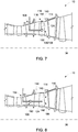
- FIG. 7 is a schematic illustration of a portion of turbine engine 10 having system 100 positioned therein.
- turbine engine 10 is minimally disassembled to provide access to maintenance location 106 within turbine engine 10.
- maintenance location 106 may be at least partially defined by component 110 having defect 112 (shown in FIG. 2 ) thereon.
- Component 110 may include, but is not limited to, a shroud member.
- maintenance location 106 is also defined by blades 114.
- Tubular assembly 124 is positioned at maintenance location 106 to facilitate maintenance of component 110, such as by repairing defect 112.
- tubular assembly 124 is routed from access point 104 and through turbine engine 10 for positioning at maintenance location 106.
- Anchoring mechanism 180 is used to couple tubular body 128 to attachment point 108. The orientation of tubular body 128 may then be adjusted to facilitate positioning dispensing nozzle 140 proximal to a damaged area 190 on component 110.
- anchoring mechanism 180 facilitates coupling tubular body 128 to rotor blades 114 of turbine engine 10, and tubular body 128 is oriented to extend in a substantially radial direction relative to centerline 36 to reach damaged area 190.
- tubular body 128 is anchored on a rotor of turbine engine 10, and the rotor is turned to circumferentially position tubular body 128 proximate a damaged component 110, positioned at a different circumferential location relative to centerline 36.
- system 100 may be used to repair turbine engine 10 without having to remove and then re-route system 100 through turbine engine 10.
- FIG. 8 is a schematic illustration of a portion of turbine engine 10 having system 100 positioned therein.
- maintenance location 106 is at least partially defined by component 110.
- Component 110 may include, but is not limited to, blade 114.
- Tubular assembly 124 is positioned at maintenance location 106 to facilitate maintaining component 110.
- tubular assembly 124 is routed from access point 104 and through turbine engine 10 for positioning at maintenance location 106.
- Anchoring mechanism 180 is used to couple tubular body 128 to attachment point 108. The orientation of tubular body 128 may then be adjusted to facilitate positioning dispensing nozzle 140 proximate a damaged area 192 on component 110.
- anchoring mechanism 180 facilitates coupling tubular body 128 to guide vanes 116 of turbine engine 10, and tubular body 128 is oriented to extend in a substantially axial direction relative to centerline 36 to reach damaged area 192.
- An exemplary technical effect of the systems and methods described herein includes at least one of: (a) enabling in-situ maintenance of interior components of a turbine engine; (b) increasing the accessibility of difficult-to-reach locations within a turbine assembly for inspection and/or in situ repair; (c) reducing the time that turbine engines are out of service for maintenance; and (d) reducing unplanned service outages for a turbine engine.
- Exemplary embodiments of methods and systems for use in repairing turbine engines are not limited to the specific embodiments described herein, but rather, components of systems and/or steps of the methods may be utilized independently and separately from other components and/or steps described herein.
- the methods and systems may also be used in combination with other systems requiring inspection and/or repair of components, and are not limited to practice with only the systems and methods as described herein.
- the exemplary embodiment can be implemented and utilized in connection with many other applications, equipment, and systems that may benefit from using a service apparatus for inspection and/or repair.
Landscapes
- Engineering & Computer Science (AREA)
- Mechanical Engineering (AREA)
- General Engineering & Computer Science (AREA)
- Physics & Mathematics (AREA)
- Multimedia (AREA)
- Astronomy & Astrophysics (AREA)
- General Physics & Mathematics (AREA)
- Optics & Photonics (AREA)
- Structures Of Non-Positive Displacement Pumps (AREA)
Applications Claiming Priority (1)
| Application Number | Priority Date | Filing Date | Title |
|---|---|---|---|
| US16/654,820 US11530621B2 (en) | 2019-10-16 | 2019-10-16 | Systems and method for use in servicing a machine |
Publications (1)
| Publication Number | Publication Date |
|---|---|
| EP3808935A1 true EP3808935A1 (fr) | 2021-04-21 |
Family
ID=72840294
Family Applications (1)
| Application Number | Title | Priority Date | Filing Date |
|---|---|---|---|
| EP20201190.4A Pending EP3808935A1 (fr) | 2019-10-16 | 2020-10-09 | Système de maintenance avec un ensemble tubulaire pour l'entretien d'une turbomachine |
Country Status (3)
| Country | Link |
|---|---|
| US (2) | US11530621B2 (fr) |
| EP (1) | EP3808935A1 (fr) |
| CN (1) | CN112657766B (fr) |
Cited By (1)
| Publication number | Priority date | Publication date | Assignee | Title |
|---|---|---|---|---|
| EP4647762A1 (fr) * | 2024-05-08 | 2025-11-12 | RTX Corporation | Inspection d'un composant de centrale électrique interne à l'aide d'une portée d'inspection |
Families Citing this family (3)
| Publication number | Priority date | Publication date | Assignee | Title |
|---|---|---|---|---|
| US11530621B2 (en) | 2019-10-16 | 2022-12-20 | General Electric Company | Systems and method for use in servicing a machine |
| EP4201603A1 (fr) * | 2021-12-21 | 2023-06-28 | Rolls-Royce plc | Moyens de rigidifier un robot à bras continu |
| DE102024113865A1 (de) * | 2024-05-17 | 2025-11-20 | Lufthansa Technik Aktiengesellschaft | Vorrichtung und Verfahren zur Beschichtung von schwer erreichbaren Oberflächen in einer Gasturbine |
Citations (10)
| Publication number | Priority date | Publication date | Assignee | Title |
|---|---|---|---|---|
| US3841764A (en) * | 1969-12-09 | 1974-10-15 | Secr Defence | Intrascope |
| US4659195A (en) * | 1986-01-31 | 1987-04-21 | American Hospital Supply Corporation | Engine inspection system |
| EP1811136A2 (fr) * | 2006-01-24 | 2007-07-25 | Rolls-Royce plc | Méthode pour fixer un composant dans un moteur |
| DE102010045869A1 (de) * | 2010-08-03 | 2012-02-23 | Mtu Aero Engines Gmbh | Reinigung einer Turbomaschinenstufe |
| EP2623731A1 (fr) * | 2012-02-06 | 2013-08-07 | Rolls-Royce Deutschland Ltd & Co KG | Appareil et procédé pour le traitement d'une aube de turbine à haute pression dans une turbine à gaz |
| US9016159B2 (en) * | 2010-09-17 | 2015-04-28 | Rolls-Royce Plc | Flexible tool |
| EP3032044A1 (fr) * | 2014-12-12 | 2016-06-15 | General Electric Company | Systèmes et procédés pour injecter des fluides dans un ou plusieurs étages d'un composant à plusieurs étages |
| US20170362939A1 (en) * | 2016-06-17 | 2017-12-21 | General Electric Company | System and method for performing an in situ repair of an internal component of a gas turbine engine |
| WO2018222174A1 (fr) * | 2017-05-30 | 2018-12-06 | General Electric Company | Appareil de service à utiliser avec des machines tournantes |
| US20190277770A1 (en) * | 2018-03-07 | 2019-09-12 | General Electric Company | Probe Insertion System |
Family Cites Families (110)
| Publication number | Priority date | Publication date | Assignee | Title |
|---|---|---|---|---|
| US4890602A (en) * | 1987-11-25 | 1990-01-02 | Hake Lawrence W | Endoscope construction with means for controlling rigidity and curvature of flexible endoscope tube |
| US4878953A (en) * | 1988-01-13 | 1989-11-07 | Metallurgical Industries, Inc. | Method of refurbishing cast gas turbine engine components and refurbished component |
| JPH0663787A (ja) | 1992-08-14 | 1994-03-08 | Olympus Optical Co Ltd | 溶接用内視鏡装置 |
| US5759151A (en) | 1995-06-07 | 1998-06-02 | Carnegie Mellon University | Flexible steerable device for conducting exploratory procedures |
| GB9816421D0 (en) | 1998-07-28 | 1998-09-23 | Keymed Medicals & Ind Equip | Apparatus for delivering laser energy to a remote location |
| WO2002050619A2 (fr) * | 2000-12-21 | 2002-06-27 | Foster-Miller, Inc. | Systeme d'inspection orientable |
| US6471862B1 (en) * | 2001-06-13 | 2002-10-29 | Robert John Rockwell | Oil skimming apparatus |
| US7154362B2 (en) * | 2003-11-12 | 2006-12-26 | Honeywell International, Inc. | Robotic member |
| US7131372B2 (en) | 2003-12-01 | 2006-11-07 | Lockheed Martin Corporation | Miniature fluid dispensing end-effector for geometrically constrained areas |
| US7789827B2 (en) * | 2006-08-21 | 2010-09-07 | Karl Storz Endovision, Inc. | Variable shaft flexibility in endoscope |
| DE102007029728A1 (de) * | 2007-06-27 | 2009-01-08 | Rolls-Royce Deutschland Ltd & Co Kg | Verfahren und Vorrichtung zur Reparatur von Blisks von Gasturbinen |
| DE102008021746A1 (de) | 2008-04-30 | 2009-11-19 | Lufthansa Technik Ag | Verfahren und Vorrichtung zum Reinigen eines Strahltriebwerks |
| US8301302B2 (en) | 2008-05-08 | 2012-10-30 | The Boeing Company | Synchronous robotic operation on a structure having a confined space |
| AU2009255959B2 (en) | 2008-06-05 | 2013-11-28 | Carnegie Mellon University | Extendable articulated probe device |
| DE102009004661A1 (de) | 2009-01-12 | 2010-07-15 | Rolls-Royce Deutschland Ltd & Co Kg | Vorrichtung zur Reparatur der Schaufeln von BLISK-Trommeln mittels Laserstrahlauftragsschweißen |
| US8666547B2 (en) | 2009-03-25 | 2014-03-04 | Massachusetts Institute Of Technology | Cellular automotion digital material |
| US20150088043A1 (en) | 2009-07-15 | 2015-03-26 | President And Fellows Of Harvard College | Actively controlled wearable orthotic devices and active modular elastomer sleeve for wearable orthotic devices |
| US20110083325A1 (en) | 2009-07-31 | 2011-04-14 | Foley Joseph Timothy | Method of Manufacturing a Nickel Titanium Coil Actuator |
| US8184151B2 (en) | 2009-09-18 | 2012-05-22 | Siemens Energy, Inc. | Flexible imaging fiber bundle monitoring system for combustion turbines |
| WO2012050938A2 (fr) | 2010-09-29 | 2012-04-19 | President And Fellows Of Harvard College | Pavé de touches tactile vestimentaire avec peau artificielle étirable |
| WO2012148472A2 (fr) | 2010-11-19 | 2012-11-01 | President And Fellows Of Harvard College | Actionneurs robotisés déformables |
| EP2505779B1 (fr) | 2011-03-28 | 2018-05-23 | General Electric Company | Procédé et système d'inspection de la clarté de l'extrémité d'une lame |
| ITFI20110091A1 (it) | 2011-05-03 | 2012-11-04 | Scuola Superiore Di Studi Universit Arie Di Perfe | Robot con arti morbidi adibiti a locomozione e presa |
| US9099233B2 (en) | 2011-09-23 | 2015-08-04 | Uchicago Argonne, Llc | Interface colloidal robotic manipulator |
| DE102011122549A1 (de) * | 2011-12-28 | 2013-07-04 | Rolls-Royce Deutschland Ltd & Co Kg | Verfahren zur Reparatur einer Einlaufschicht eines Verdichters einer Gasturbine |
| AU2013209422B2 (en) | 2012-01-19 | 2017-08-17 | President And Fellows Of Harvard College | Flexible robotic actuators |
| KR102044052B1 (ko) | 2012-02-28 | 2019-11-12 | 프레지던트 앤드 펠로우즈 오브 하바드 칼리지 | 공기압식 액츄에이터로서 패브릭-엘라스토머 복합체를 제공하기 위한 장치, 시스템 및 방법 |
| WO2013148340A2 (fr) | 2012-03-26 | 2013-10-03 | President And Fellows Of Harvard College | Systèmes et méthodes fournissant des actionneurs robotiques flexibles |
| KR101941569B1 (ko) | 2012-03-30 | 2019-04-15 | 삼성전자주식회사 | 가변 유연관 및 이를 갖춘 매니퓰레이터 |
| ITFI20120082A1 (it) | 2012-04-23 | 2013-10-24 | Scuola Superiore Di Studi Universit Ari E Di Perfe | Dispositivo di propulsione acquatica a getti pulsati |
| US9445711B2 (en) | 2012-05-09 | 2016-09-20 | Carnegie Mellon University | System and method to magnetically actuate a capsule endoscopic robot for diagnosis and treatment |
| US10406698B2 (en) | 2012-07-18 | 2019-09-10 | President And Fellows Of Harvard College | Apparatus, systems, and methods for modular soft robots |
| GB201216703D0 (en) | 2012-09-19 | 2012-10-31 | Rolls Royce Plc | A boroscope and a method of laser processing a component within an assembled apparatus using a boroscope |
| JP2016500795A (ja) | 2012-10-22 | 2016-01-14 | プレジデント アンド フェローズ オブ ハーバード カレッジ | 加圧可能チャンバを作動させるための装置、システム、及び方法 |
| KR102052236B1 (ko) | 2013-03-04 | 2019-12-04 | 프레지던트 앤드 펠로우즈 오브 하바드 칼리지 | 경질 구성요소를 지닌 연질 로봇의 자기적 조립 |
| WO2014165908A1 (fr) | 2013-04-09 | 2014-10-16 | Monash University | Procédé et dispositif de détection intelligente |
| WO2014169119A1 (fr) | 2013-04-10 | 2014-10-16 | President And Fellows Of Harvard College | Conducteurs ioniques étirables pour des actionneurs et des capteurs transparents |
| WO2014176697A1 (fr) | 2013-04-30 | 2014-11-06 | Chen haotian | Dispositifs microfluidiques et procédés d'extrusion de structures tubulaires |
| WO2014196928A1 (fr) | 2013-06-04 | 2014-12-11 | National University Of Singapore | Dispositif de préhension |
| WO2014204323A1 (fr) | 2013-06-17 | 2014-12-24 | Stretchsense Limited | Capteurs textiles étirables |
| US9835184B2 (en) | 2013-08-10 | 2017-12-05 | The Regents Of The University Of Michigan | Fiber-reinforced actuator |
| US10814351B2 (en) | 2013-08-12 | 2020-10-27 | The Boeing Company | High-viscosity sealant application system |
| US10639801B2 (en) | 2013-08-20 | 2020-05-05 | President And Fellows Of Harvard College | Low strain pneumatic networks for soft robots |
| EP3052204B1 (fr) | 2013-10-01 | 2025-04-30 | President and Fellows of Harvard College | Fabrication de dispositifs souples à partir de matériaux en feuilles |
| EP3071939B1 (fr) | 2013-11-18 | 2019-07-31 | President and Fellows of Harvard College | Capteur de contrainte extensible imprimé |
| WO2015138649A1 (fr) | 2014-03-11 | 2015-09-17 | Soft Robotics, Inc. | Instrument laparoscopique autoconformable souple |
| US20150257968A1 (en) | 2014-03-11 | 2015-09-17 | Carl E. VAUSE | Soft conformal compression devices and methods |
| WO2015143404A1 (fr) | 2014-03-20 | 2015-09-24 | Soft Robotics, Inc. | Dispositif orthopédique robotique souple |
| WO2015157621A1 (fr) | 2014-04-10 | 2015-10-15 | President And Fellows Of Harvard College | Rétracteur robotique ayant un actionneur renforcé par des fibres |
| US10006444B2 (en) | 2014-04-11 | 2018-06-26 | President And Fellows Of Harvard College | High throughput fabrication of soft machines |
| US9850922B2 (en) | 2014-04-14 | 2017-12-26 | President And Fellows Of Harvard College | Soft buckling actuators |
| US20170051806A1 (en) | 2014-04-24 | 2017-02-23 | President And Fellows Of Harvard College | Shape Recoverable And Reusable Energy Absorbing Structures, Systems And Methods For Manufacture Thereof |
| WO2015172067A1 (fr) | 2014-05-08 | 2015-11-12 | The Trustees Of Columbia University In The City Of New York | Moteurs entraînés par évaporation |
| US20150343649A1 (en) | 2014-05-28 | 2015-12-03 | Richard Galinson | Tentacle mechanism |
| CN107002721A (zh) | 2014-06-09 | 2017-08-01 | 软机器人公司 | 使用非对称表面的软机器人致动器 |
| WO2015191007A1 (fr) | 2014-06-12 | 2015-12-17 | National University Of Singapore | Dispositif d'actionneur, procédé et système pour la rééducation de membre |
| WO2015191122A1 (fr) | 2014-06-13 | 2015-12-17 | Worcester Polytechnic Institute | Actionneurs et procédés d'utilisation |
| US9719534B2 (en) * | 2014-06-26 | 2017-08-01 | President And Fellows Of Harvard College | Pneumatic insect robots |
| WO2016053430A2 (fr) | 2014-06-30 | 2016-04-07 | President And Fellows Of Harvard College | Robot souple autonome et résistant |
| WO2016019087A1 (fr) | 2014-07-31 | 2016-02-04 | President And Fellows Of Harvard College | Fibre de capteur souple et procédé de fabrication d'une fibre de capteur souple |
| CA2958921C (fr) | 2014-08-22 | 2023-02-07 | President And Fellows Of Harvard College | Capteurs pour robots souples et actionneurs souples |
| WO2016077358A1 (fr) | 2014-11-13 | 2016-05-19 | Soft Robotics, Inc. | Écarteurs robotiques souples |
| US10189168B2 (en) | 2014-11-18 | 2019-01-29 | Soft Robotics, Inc. | Soft robotic actuator enhancements |
| GB201420644D0 (en) | 2014-11-20 | 2015-01-07 | Technion Res & Dev Foundation | Solid-liquid composite structures |
| US10226304B2 (en) | 2014-12-15 | 2019-03-12 | The Johns Hopkins University | Shape tracking of a dexterous continuum manipulator |
| US20160270940A1 (en) | 2015-03-20 | 2016-09-22 | Carl Everett Vause | Soft robotic orthopedic device |
| GB201504843D0 (en) | 2015-03-23 | 2015-05-06 | Rolls Royce Plc | Flexible tools and apparatus for machining objects |
| CN108025443B (zh) | 2015-04-23 | 2019-07-23 | 软机器人公司 | 机器人抓持器以及机器人结构 |
| WO2016176340A2 (fr) | 2015-04-27 | 2016-11-03 | Regents Of The University Of Minnesota | Robots souples, actionneurs souples et leurs procédés de fabrication |
| WO2016201418A1 (fr) | 2015-06-11 | 2016-12-15 | Soft Robotics, Inc. | Systèmes robotiques modulaires |
| EP4019209B1 (fr) | 2015-06-26 | 2024-11-13 | Soft Robotics, Inc. | Pince de manipulation d'aliments |
| WO2017058334A2 (fr) | 2015-07-10 | 2017-04-06 | President And Fellows Of Harvard College | Robot hybride imprimé en 3d |
| JP2018523584A (ja) | 2015-07-13 | 2018-08-23 | プレジデント アンド フェローズ オブ ハーバード カレッジ | ソフトロボットのための分散型加圧及び排出システム |
| US20180188125A1 (en) | 2015-07-22 | 2018-07-05 | Carnegie Mellon University | Flexible and Stretchable Sensor Using Soft Optical Waveguides |
| EP3964335A1 (fr) | 2015-07-30 | 2022-03-09 | Soft Robotics, Inc. | Système de préhension robotique autonome |
| CN107923571B (zh) | 2015-08-14 | 2020-10-23 | 国立研究开发法人科学技术振兴机构 | 可折结构物、以及可折结构物制造方法、可折结构物制造装置及记录介质 |
| WO2017044617A1 (fr) | 2015-09-08 | 2017-03-16 | The Regents Of The University Of California | Capteurs tactiles et procédés de fabrication de capteurs tactiles |
| WO2017074925A1 (fr) | 2015-10-26 | 2017-05-04 | President And Fellows Of Harvard College | Architecture permettant de réaliser une propagation d'onde stable dans un matériau mou |
| US11135028B2 (en) | 2015-10-31 | 2021-10-05 | Children's National Medical Center | Soft surgical tools |
| US10035263B2 (en) | 2015-11-03 | 2018-07-31 | Kurion, Inc. | System and method for inspection and maintenance of hazardous spaces |
| US11197726B2 (en) | 2015-11-06 | 2021-12-14 | Iowa State University Research Foundation, Inc. | Microrobotic tentacles with spiral bending capability based on shape-engineered elastomeric microtubes and methods of manufacturing same |
| US20200061810A9 (en) | 2015-11-10 | 2020-02-27 | The Regents Of The University Of California | Modular rod-centered, distributed actuation and control architecture for spherical tensegrity robots |
| WO2017083350A1 (fr) | 2015-11-12 | 2017-05-18 | President And Fellows Of Harvard College | Actionneurs |
| US10378358B2 (en) | 2015-11-19 | 2019-08-13 | Rutgers, The State University Of New Jersey | Rotary actuator utilizing pneumatically actuated elastomeric structures |
| US10824282B2 (en) | 2015-11-30 | 2020-11-03 | Drexel University | Fabric touch sensor |
| CN108778640B (zh) | 2016-01-20 | 2019-10-22 | 软机器人公司 | 用于杂乱抓持环境、高加速度移动、食品操作以及自动化仓储系统的软机器人抓持器 |
| US10094221B2 (en) | 2016-02-03 | 2018-10-09 | General Electric Company | In situ gas turbine prevention of crack growth progression |
| US10443385B2 (en) * | 2016-02-03 | 2019-10-15 | General Electric Company | In situ gas turbine prevention of crack growth progression via laser welding |
| US10737409B2 (en) | 2016-02-25 | 2020-08-11 | Industry-Academic Cooperation Foundation, Yonsei University | Apparatus and method of controlling stiffness of soft material |
| CA3015906A1 (fr) | 2016-02-25 | 2017-08-31 | Cornell University | Guides d'ondes destines a etre utilises dans des capteurs ou des dispositifs d'affichage |
| US11773516B2 (en) | 2016-03-21 | 2023-10-03 | Board Of Regents, The University Of Texas System | Actuating textiles containing polymer fiber muscles |
| US11135716B2 (en) | 2016-03-30 | 2021-10-05 | B.G. Negev Technologies & Applications Ltd., At Ben-Gurion University | Minimally actuated serial robot |
| WO2017177126A1 (fr) | 2016-04-07 | 2017-10-12 | Soft Robotics, Inc. | Actionneurs robotiques souples pour positionnement, emballage et assemblage |
| EP3244062A1 (fr) | 2016-05-10 | 2017-11-15 | Technische Hochschule Nuernberg Georg-Simon-Ohm | Actionneur activé thermiquement et procédé de fabrication d'un actionneur activé thermiquement |
| US12022994B2 (en) | 2016-05-16 | 2024-07-02 | President And Fellows Of Harvard College | Soft actuators for pop-up laminate structures |
| WO2018005144A2 (fr) | 2016-06-17 | 2018-01-04 | Cornell University | Actionneurs à base de mousse |
| EP3260250B1 (fr) | 2016-06-21 | 2019-10-02 | Ansaldo Energia IP UK Limited | Système robotique pour des opérations de fond de l'espace confiné |
| US10240688B2 (en) | 2016-06-29 | 2019-03-26 | Ecole Polytechnique Federale De Lausanne (Epfl) | Device having a plurality of latching micro-actuators and method of operating the same |
| US10920590B2 (en) * | 2016-06-30 | 2021-02-16 | General Electric Company | Turbine assembly maintenance methods |
| US10586913B2 (en) | 2016-08-11 | 2020-03-10 | Postech Academy-Industry Foundation | Electroactive actuator, mechanical device including the same, and polymer electrolyte |
| US10473093B2 (en) | 2016-08-26 | 2019-11-12 | Daegu Gyeongbuk Institute Of Science And Technology | Soft actuator using thermoelectric effect |
| CN109996490B (zh) | 2016-09-28 | 2023-01-10 | 项目莫里股份有限公司 | 用于机器人导管系统和其它用途的基站、充电站和/或服务器以及改进的铰转装置和系统 |
| US11067002B2 (en) * | 2016-12-06 | 2021-07-20 | General Electric Company | Gas turbine engine maintenance tool |
| WO2018130295A1 (fr) | 2017-01-13 | 2018-07-19 | MAX-PLANCK-Gesellschaft zur Förderung der Wissenschaften e.V. | Procédé d'actionnement d'un élément à forme variable, élément à forme variable et système d'actionnement |
| GB2560354A (en) | 2017-03-09 | 2018-09-12 | Rolls Royce Plc | Continuum robots |
| US10494926B2 (en) * | 2017-08-28 | 2019-12-03 | General Electric Company | System and method for maintaining machines |
| JP6941048B2 (ja) * | 2017-12-27 | 2021-09-29 | オリンパス株式会社 | 内視鏡装置、内視鏡装置の作動方法、内視鏡システム、および内視鏡用光学アダプタ |
| US10962345B2 (en) * | 2018-05-23 | 2021-03-30 | General Electric Company | Tool and method for inspecting an annular space of an engine |
| US11530621B2 (en) | 2019-10-16 | 2022-12-20 | General Electric Company | Systems and method for use in servicing a machine |
| US10884232B1 (en) * | 2019-12-30 | 2021-01-05 | General Electric Company | Insertion apparatus including rigidizable body |
-
2019
- 2019-10-16 US US16/654,820 patent/US11530621B2/en active Active
-
2020
- 2020-10-09 EP EP20201190.4A patent/EP3808935A1/fr active Pending
- 2020-10-16 CN CN202011109973.0A patent/CN112657766B/zh active Active
-
2022
- 2022-11-22 US US17/992,395 patent/US12258873B2/en active Active
Patent Citations (10)
| Publication number | Priority date | Publication date | Assignee | Title |
|---|---|---|---|---|
| US3841764A (en) * | 1969-12-09 | 1974-10-15 | Secr Defence | Intrascope |
| US4659195A (en) * | 1986-01-31 | 1987-04-21 | American Hospital Supply Corporation | Engine inspection system |
| EP1811136A2 (fr) * | 2006-01-24 | 2007-07-25 | Rolls-Royce plc | Méthode pour fixer un composant dans un moteur |
| DE102010045869A1 (de) * | 2010-08-03 | 2012-02-23 | Mtu Aero Engines Gmbh | Reinigung einer Turbomaschinenstufe |
| US9016159B2 (en) * | 2010-09-17 | 2015-04-28 | Rolls-Royce Plc | Flexible tool |
| EP2623731A1 (fr) * | 2012-02-06 | 2013-08-07 | Rolls-Royce Deutschland Ltd & Co KG | Appareil et procédé pour le traitement d'une aube de turbine à haute pression dans une turbine à gaz |
| EP3032044A1 (fr) * | 2014-12-12 | 2016-06-15 | General Electric Company | Systèmes et procédés pour injecter des fluides dans un ou plusieurs étages d'un composant à plusieurs étages |
| US20170362939A1 (en) * | 2016-06-17 | 2017-12-21 | General Electric Company | System and method for performing an in situ repair of an internal component of a gas turbine engine |
| WO2018222174A1 (fr) * | 2017-05-30 | 2018-12-06 | General Electric Company | Appareil de service à utiliser avec des machines tournantes |
| US20190277770A1 (en) * | 2018-03-07 | 2019-09-12 | General Electric Company | Probe Insertion System |
Cited By (1)
| Publication number | Priority date | Publication date | Assignee | Title |
|---|---|---|---|---|
| EP4647762A1 (fr) * | 2024-05-08 | 2025-11-12 | RTX Corporation | Inspection d'un composant de centrale électrique interne à l'aide d'une portée d'inspection |
Also Published As
| Publication number | Publication date |
|---|---|
| US11530621B2 (en) | 2022-12-20 |
| US12258873B2 (en) | 2025-03-25 |
| US20210115809A1 (en) | 2021-04-22 |
| CN112657766A (zh) | 2021-04-16 |
| CN112657766B (zh) | 2023-12-05 |
| US20230085301A1 (en) | 2023-03-16 |
Similar Documents
| Publication | Publication Date | Title |
|---|---|---|
| US12258873B2 (en) | Systems and method for use in servicing a machine | |
| US11739695B2 (en) | Gas turbine engine maintenance tool | |
| US12420953B2 (en) | Inspection and repair tool | |
| EP3208432B1 (fr) | Système et procédé de réparation d'un matériau abradable | |
| US9403244B2 (en) | Method for repairing an abradable coating of a compressor of a gas turbine | |
| EP3663515B1 (fr) | Appareil de service à utiliser avec d'assemblages de turbine | |
| US11111813B2 (en) | Gas turbine engine maintenance method | |
| EP3222813B1 (fr) | Procédés de fixer des outils dans un moteur de turbine à gaz | |
| US10190442B2 (en) | Gas turbine in situ inflatable bladders for on-wing repair | |
| EP3208418B1 (fr) | Système de réparation d'une déformation dans une pale de turbine | |
| CN112664278B (zh) | 维修涡轮机的系统及方法 | |
| EP3203017B1 (fr) | Procédé pour arrêter une fissure dans un composant d'un moteur de turbine à gaz pour effectuer une réparation in situ | |
| US10563510B2 (en) | System and method for in situ repair of gas turbine engines | |
| EP3718679A1 (fr) | Système de réparation de soudure | |
| US10988268B2 (en) | System and method for performing operations on an engine | |
| EP4517044A1 (fr) | Système et procédé de réparation d'un composant multicouche d'un moteur |
Legal Events
| Date | Code | Title | Description |
|---|---|---|---|
| PUAI | Public reference made under article 153(3) epc to a published international application that has entered the european phase |
Free format text: ORIGINAL CODE: 0009012 |
|
| STAA | Information on the status of an ep patent application or granted ep patent |
Free format text: STATUS: THE APPLICATION HAS BEEN PUBLISHED |
|
| AK | Designated contracting states |
Kind code of ref document: A1 Designated state(s): AL AT BE BG CH CY CZ DE DK EE ES FI FR GB GR HR HU IE IS IT LI LT LU LV MC MK MT NL NO PL PT RO RS SE SI SK SM TR |
|
| AX | Request for extension of the european patent |
Extension state: BA ME |
|
| STAA | Information on the status of an ep patent application or granted ep patent |
Free format text: STATUS: REQUEST FOR EXAMINATION WAS MADE |
|
| 17P | Request for examination filed |
Effective date: 20211018 |
|
| RBV | Designated contracting states (corrected) |
Designated state(s): AL AT BE BG CH CY CZ DE DK EE ES FI FR GB GR HR HU IE IS IT LI LT LU LV MC MK MT NL NO PL PT RO RS SE SI SK SM TR |
|
| STAA | Information on the status of an ep patent application or granted ep patent |
Free format text: STATUS: EXAMINATION IS IN PROGRESS |
|
| 17Q | First examination report despatched |
Effective date: 20230324 |