EP3808960B1 - Procédé de gestion du couple d'un véhicule automobile comportant un moteur à combustion interne et estimation de l usure d'un tel moteur - Google Patents
Procédé de gestion du couple d'un véhicule automobile comportant un moteur à combustion interne et estimation de l usure d'un tel moteur Download PDFInfo
- Publication number
- EP3808960B1 EP3808960B1 EP20200386.9A EP20200386A EP3808960B1 EP 3808960 B1 EP3808960 B1 EP 3808960B1 EP 20200386 A EP20200386 A EP 20200386A EP 3808960 B1 EP3808960 B1 EP 3808960B1
- Authority
- EP
- European Patent Office
- Prior art keywords
- adjusted
- engine
- pcyl
- pressure
- cylinders
- Prior art date
- Legal status (The legal status is an assumption and is not a legal conclusion. Google has not performed a legal analysis and makes no representation as to the accuracy of the status listed.)
- Active
Links
Images
Classifications
-
- F—MECHANICAL ENGINEERING; LIGHTING; HEATING; WEAPONS; BLASTING
- F02—COMBUSTION ENGINES; HOT-GAS OR COMBUSTION-PRODUCT ENGINE PLANTS
- F02D—CONTROLLING COMBUSTION ENGINES
- F02D41/00—Electrical control of supply of combustible mixture or its constituents
- F02D41/0002—Controlling intake air
- F02D41/0007—Controlling intake air for control of turbo-charged or super-charged engines
-
- F—MECHANICAL ENGINEERING; LIGHTING; HEATING; WEAPONS; BLASTING
- F02—COMBUSTION ENGINES; HOT-GAS OR COMBUSTION-PRODUCT ENGINE PLANTS
- F02D—CONTROLLING COMBUSTION ENGINES
- F02D11/00—Arrangements for, or adaptations to, non-automatic engine control initiation means, e.g. operator initiated
- F02D11/06—Arrangements for, or adaptations to, non-automatic engine control initiation means, e.g. operator initiated characterised by non-mechanical control linkages, e.g. fluid control linkages or by control linkages with power drive or assistance
- F02D11/10—Arrangements for, or adaptations to, non-automatic engine control initiation means, e.g. operator initiated characterised by non-mechanical control linkages, e.g. fluid control linkages or by control linkages with power drive or assistance of the electric type
- F02D11/105—Arrangements for, or adaptations to, non-automatic engine control initiation means, e.g. operator initiated characterised by non-mechanical control linkages, e.g. fluid control linkages or by control linkages with power drive or assistance of the electric type characterised by the function converting demand to actuation, e.g. a map indicating relations between an accelerator pedal position and throttle valve opening or target engine torque
-
- F—MECHANICAL ENGINEERING; LIGHTING; HEATING; WEAPONS; BLASTING
- F02—COMBUSTION ENGINES; HOT-GAS OR COMBUSTION-PRODUCT ENGINE PLANTS
- F02D—CONTROLLING COMBUSTION ENGINES
- F02D31/00—Use of speed-sensing governors to control combustion engines, not otherwise provided for
- F02D31/001—Electric control of rotation speed
- F02D31/007—Electric control of rotation speed controlling fuel supply
-
- F—MECHANICAL ENGINEERING; LIGHTING; HEATING; WEAPONS; BLASTING
- F02—COMBUSTION ENGINES; HOT-GAS OR COMBUSTION-PRODUCT ENGINE PLANTS
- F02D—CONTROLLING COMBUSTION ENGINES
- F02D35/00—Controlling engines, dependent on conditions exterior or interior to engines, not otherwise provided for
- F02D35/02—Controlling engines, dependent on conditions exterior or interior to engines, not otherwise provided for on interior conditions
- F02D35/023—Controlling engines, dependent on conditions exterior or interior to engines, not otherwise provided for on interior conditions by determining the cylinder pressure
-
- F—MECHANICAL ENGINEERING; LIGHTING; HEATING; WEAPONS; BLASTING
- F02—COMBUSTION ENGINES; HOT-GAS OR COMBUSTION-PRODUCT ENGINE PLANTS
- F02D—CONTROLLING COMBUSTION ENGINES
- F02D41/00—Electrical control of supply of combustible mixture or its constituents
- F02D41/02—Circuit arrangements for generating control signals
- F02D41/04—Introducing corrections for particular operating conditions
- F02D41/10—Introducing corrections for particular operating conditions for acceleration
-
- F—MECHANICAL ENGINEERING; LIGHTING; HEATING; WEAPONS; BLASTING
- F02—COMBUSTION ENGINES; HOT-GAS OR COMBUSTION-PRODUCT ENGINE PLANTS
- F02D—CONTROLLING COMBUSTION ENGINES
- F02D2200/00—Input parameters for engine control
- F02D2200/02—Input parameters for engine control the parameters being related to the engine
- F02D2200/04—Engine intake system parameters
- F02D2200/0406—Intake manifold pressure
-
- F—MECHANICAL ENGINEERING; LIGHTING; HEATING; WEAPONS; BLASTING
- F02—COMBUSTION ENGINES; HOT-GAS OR COMBUSTION-PRODUCT ENGINE PLANTS
- F02D—CONTROLLING COMBUSTION ENGINES
- F02D2200/00—Input parameters for engine control
- F02D2200/02—Input parameters for engine control the parameters being related to the engine
- F02D2200/10—Parameters related to the engine output, e.g. engine torque or engine speed
- F02D2200/1002—Output torque
-
- F—MECHANICAL ENGINEERING; LIGHTING; HEATING; WEAPONS; BLASTING
- F02—COMBUSTION ENGINES; HOT-GAS OR COMBUSTION-PRODUCT ENGINE PLANTS
- F02D—CONTROLLING COMBUSTION ENGINES
- F02D2200/00—Input parameters for engine control
- F02D2200/02—Input parameters for engine control the parameters being related to the engine
- F02D2200/10—Parameters related to the engine output, e.g. engine torque or engine speed
- F02D2200/101—Engine speed
-
- F—MECHANICAL ENGINEERING; LIGHTING; HEATING; WEAPONS; BLASTING
- F02—COMBUSTION ENGINES; HOT-GAS OR COMBUSTION-PRODUCT ENGINE PLANTS
- F02D—CONTROLLING COMBUSTION ENGINES
- F02D2250/00—Engine control related to specific problems or objectives
- F02D2250/18—Control of the engine output torque
- F02D2250/26—Control of the engine output torque by applying a torque limit
-
- Y—GENERAL TAGGING OF NEW TECHNOLOGICAL DEVELOPMENTS; GENERAL TAGGING OF CROSS-SECTIONAL TECHNOLOGIES SPANNING OVER SEVERAL SECTIONS OF THE IPC; TECHNICAL SUBJECTS COVERED BY FORMER USPC CROSS-REFERENCE ART COLLECTIONS [XRACs] AND DIGESTS
- Y02—TECHNOLOGIES OR APPLICATIONS FOR MITIGATION OR ADAPTATION AGAINST CLIMATE CHANGE
- Y02T—CLIMATE CHANGE MITIGATION TECHNOLOGIES RELATED TO TRANSPORTATION
- Y02T10/00—Road transport of goods or passengers
- Y02T10/10—Internal combustion engine [ICE] based vehicles
- Y02T10/12—Improving ICE efficiencies
Definitions
- the present invention relates, in general, to the supercharging of a traction device comprising an internal combustion engine equipped with a turbocharger.
- the invention relates to a method for managing the torque of a motor vehicle comprising an internal combustion engine equipped with a turbocharger, and to estimating the wear of such an engine.
- an internal combustion engine is based on the combustion of a mixture of air and fuel. Its power depends on the amount of fuel burned during a cycle, and therefore on the filling capacity of its cylinders.
- Engine efficiency and performance can be increased by supercharging, i.e. by increasing the amount of air admitted into the cylinders.
- Supercharging is typically provided by a turbocharger.
- the turbocharger consists of a turbine driven by the engine's exhaust gases and a compressor driven by the turbine.
- the compressor increases the pressure Pcol in the intake manifold and thus increases the amount of air entering the cylinders and the amount of fuel injected into the cylinders.
- the vehicle detects a maximum torque setpoint.
- the pressure Pcol in the intake manifold and the pressure Pcyl in the cylinders is increased to a predetermined maximum value, respectively Pcol,max and Pcyl,max.
- the maximum pressure Pcol,max in the intake manifold and the maximum cylinder pressure Pcyl,max in the cylinders are adjusted and increased, respectively, up to a higher pressure Pcol,a in the intake manifold and a higher cylinder pressure Pcyl,a in the cylinders.
- the invention therefore aims to remedy these drawbacks and to propose a method for exploiting the pressure in the cylinders while controlling and preventing the risks of engine failure, in particular caused by wear of the connecting rod bearings, generated by the activation of the overtorque function.
- the adjusted pressure Pcyl,a in the cylinders applied to meet the adjusted torque setpoint Ca is limited when the value v corresponding to an estimate of the engine wear level is greater than or equal to a predetermined threshold.
- the application of an adjusted pressure Pcyl,a in the cylinders to meet the adjusted torque setpoint Ca is deactivated when the value v corresponding to an estimate of the level of wear of the engine is greater than or equal to a predetermined threshold.
- the coefficient c is exponentially variable between 0 and 1 depending on the difference ⁇ Pcyl between the maximum pressure Pcyl,max and the adjusted pressure Pcyl,a in the cylinders.
- the engine revolution number can be measured by a counter, and the counter can be reset when changing the engine connecting rod bearings.
- the coefficient c can be equal to [exp( ⁇ Pcyl)-1]/[exp( ⁇ Pcyl,max)-1], where ⁇ Pcyl,max corresponds to the largest possible value of the difference ⁇ Pcyl between the maximum pressure Pcyl,max and the adjusted pressure Pcyl,a in the cylinders.
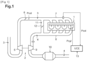
- FIG. 1 illustrates a traction device for a motor vehicle comprising a combustion engine 1 and a turbocharger 2.
- the engine is a four-cylinder diesel engine including a variable geometry turbocharger.
- Each cylinder in which there is a pressure Pcyl is advantageously equipped with an injector for injecting fuel into the engine.
- An intake circuit 3 allows the admission of air into the cylinders of the engine 1 and an exhaust circuit 4 allows the exhaust of the gases produced after combustion.
- a compressor 5 of the turbocharger is arranged upstream of the cylinders and is configured to compress the air passing through it in order to increase the quantity of air admitted into the cylinders.
- An intake flap 6 controls the air intake into an intake manifold 7 of the intake circuit 3 where a boost pressure Pcol prevails.
- the exhaust gases exit into an exhaust manifold 8 of the exhaust circuit 4 and head towards a turbine 9 of the turbocharger, arranged downstream of the cylinders and configured to expand the air passing through it.
- a pollution control device such as a particle filter 10 is also provided downstream of the turbine 9.
- the engine 1 is further associated with an exhaust gas recirculation circuit 11, used to reinject a portion of these gases into the intake manifold 7 so as, in particular, to limit the quantity of nitrogen oxide produced while avoiding the formation of smoke in the exhaust gases.
- This circuit 11 comprises advantageously a solenoid valve 12 which makes it possible to control the flow of recirculated exhaust gases.
- an electronic control unit UCE designated by the reference numeral 13, recovers signals Pcol and Pcyl for measuring the pressure prevailing respectively in the intake manifold and in the cylinders, delivered by suitable measuring sensors provided for this purpose (not shown). It acts on an exhaust gas power adjustment member, for example a wastegate or on the blades of the turbine 9 so as to regulate the value of the pressure prevailing in the intake manifold 7 and in the cylinders.
- the ECU 13 also ensures the operational control of the engine, in a manner known per se. It acts in particular on the solenoid valve 12 to adjust the quantity of recirculated gases and adjusts the operating point of the engine.
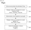
- FIG 2 illustrates a method of managing the torque of an internal combustion engine, such as engine 1, in accordance with the invention.
- Initial depression Ei means a depression of a degree lower than a maximum depression Emax of the accelerator pedal or “foot at full throttle”.
- initial torque setpoint Ci we mean a torque setpoint lower than a maximum torque setpoint Cmax.
- an adjusted torque setpoint Ca i.e. an over-torque request or “over-torque” function, greater than the maximum torque setpoint Cmax is detected, an adjusted quantity of fuel Qa is injected, then an adjusted pressure Pcol,a in the intake manifold and an adjusted pressure Pcyl,a in the cylinders are applied, for a predetermined duration ⁇ t, to meet the adjusted torque setpoint Ca.
- the maximum pressure Pcyl,max in the cylinders and the adjusted pressure Pcyl,a in the cylinders can be adjusted by means of the injection advance adjustment.
- the number of revolutions made by the engine is measured by a counter.
- the sum of the number of revolutions made by the engine at each application of the adjusted torque setpoint Ca is then multiplied by a coefficient c depending on the difference ⁇ Pcyl between the maximum pressure Pcyl,max and the adjusted pressure Pcyl,a in the cylinders.
- the coefficient c varies exponentially between 0 and 1 depending on the difference ⁇ Pcyl between the maximum pressure Pcyl,max in the cylinders and the adjusted pressure Pcyl,a in the cylinders.
- the value 1 of the coefficient can be associated with the value ⁇ Pcyl corresponding to the largest difference ⁇ Pcyl,max between the maximum pressure Pcyl,max in the cylinders and the adjusted pressure Pcyl,a.
- the value 0 of the coefficient can be associated with the value ⁇ Pcyl corresponding to the smallest difference, or even a difference that is almost zero.
- the value v calculated for example by a computer in the motor vehicle, reflects a level of wear of the engine and gives an indication of the risks of engine failure.
- the coefficient c is equal to [exp( ⁇ Pcyl)-1]/[exp( ⁇ Pcyl,max)-1], where ⁇ Pcyl,max corresponds to the largest possible value of the deviation ⁇ Pcyl between the maximum pressure Pcyl,max and the adjusted pressure Pcyl,a in the cylinders.
- a threshold value v can be predetermined.
- the adjusted pressure Pcyl,a in the cylinders applied when the request for an adjusted torque setpoint Ca is determined can be limited when the value v obtained is greater than or equal to a predetermined threshold.
- the adjusted pressure Pcyl,a in the cylinders can be limited to 2/3 of its initial value, while the adjusted fuel quantity Qa and the adjusted pressure Pcol,a in the intake manifold can be maintained at their initial value.
- the application of a cylinder pressure Pcyl,a in the cylinders when the request for an adjusted torque setpoint Ca is determined can be deactivated, while the adjusted fuel quantity Qa and the adjusted pressure Pcol,a in the intake manifold can be maintained at their initial value.
- the threshold will be advantageously chosen so as to avoid any damage to the engine which could lead to failures.
- the threshold may be determined based on engine wear tests, particularly of connecting rod bearings, at one or more engine operating points.
- the engine revolutions are measured by a counter.
- the counter may be configured so that the engine revolutions are zero when the engine is new.
- the counter can be reset when changing the engine connecting rod bearings.
Landscapes
- Engineering & Computer Science (AREA)
- Chemical & Material Sciences (AREA)
- Combustion & Propulsion (AREA)
- Mechanical Engineering (AREA)
- General Engineering & Computer Science (AREA)
- Combined Controls Of Internal Combustion Engines (AREA)
- Supercharger (AREA)
- Electrical Control Of Air Or Fuel Supplied To Internal-Combustion Engine (AREA)
- Output Control And Ontrol Of Special Type Engine (AREA)
Description
- La présente invention concerne, de manière générale, la suralimentation d'un dispositif de traction comprenant un moteur à combustion interne équipé d'un turbocompresseur.
- En particulier, l'invention se rapporte à un procédé de gestion du couple d'un véhicule automobile comprenant un moteur à combustion interne équipé d'un turbocompresseur, et à l'estimation de l'usure d'un tel moteur.
- Le fonctionnement d'un moteur à combustion interne repose sur la combustion d'un mélange d'air et de carburant. Sa puissance dépend de la quantité de carburant brûlé pendant un cycle, et par conséquent de la capacité de remplissage de ses cylindres.
- Le rendement et les performances du moteur peuvent être augmentés par suralimentation, c'est-à-dire par l'accroissement de la quantité d'air admise dans les cylindres.
- La suralimentation est classiquement assurée par un turbocompresseur. Le turbocompresseur comprend une turbine entraînée en rotation par les gaz d'échappement du moteur ainsi qu'un compresseur entraîné par la turbine. Le compresseur augmente la pression Pcol dans le collecteur d'admission et permet ainsi d'augmenter la quantité d'air entrant dans les cylindres et la quantité de carburant injectée dans les cylindres.
- Il est également possible d'augmenter la pression Pcyl dans les cylindres via le réglage de la valeur d'avance à l'injection du carburant.
- Lorsque le conducteur enfonce la pédale d'accélérateur selon un enfoncement maximale Emax, le véhicule détecte une consigne de couple maximal. La pression Pcol dans le collecteur d'admission et la pression Pcyl dans les cylindres est augmentée jusqu'à une valeur maximale prédéterminée, respectivement Pcol,max et Pcyl,max.
- Certains moteurs équipés de turbocompresseur utilisent une fonction de surcouple, dite « over-torque », consistant à augmenter temporairement leur couple maximum (voir par exemple
DE102006003883A1 ). - Pour cela, la pression maximale Pcol,max dans le collecteur d'admission et la pression de cylindre maximale Pcyl,max dans les cylindres sont ajustées et augmentées, respectivement, jusqu'à une pression supérieure Pcol,a dans le collecteur d'admission et une pression de cylindre supérieure Pcyl,a dans les cylindres.
- Cependant, l'augmentation de la pression dans les cylindres vers une pression Pcyl,a supérieure à la pression de cylindre maximale Pcyl,max peut provoquer l'usure des coussinets de bielle et engendrer des défaillances du moteur.
- Il est donc nécessaire de prendre en considération les conséquences de l'activation de la fonction de surcouple sur l'intégrité du moteur.
- L'invention a donc pour but de remédier à ces inconvénients et de proposer un procédé permettant d'exploiter la pression dans les cylindres tout en contrôlant et prévenant les risques de défaillance du moteur, notamment provoquée par l'usure des coussinets de bielle, engendrés par l'activation de la fonction de surcouple.
- Il est donc proposé un procédé de gestion du couple d'un moteur à combustion interne d'un véhicule automobile équipé d'un turbocompresseur et estimation de l'usure d'un tel moteur, le procédé comprenant :
- la détermination d'une consigne de couple maximal Cmax résultant d'un enfoncement maximal Emax de la pédale d'accélération ;
- l'application d'une quantité de carburant maximale Qmax, d'une pression maximale Pcol,max dans le collecteur d'admission et d'une pression maximale Pcyl,max dans les cylindres, pour répondre à la consigne de couple maximal Cmax ;
- la détermination d'une consigne de couple ajustée Ca, supérieure à la consigne de couple maximal Cmax ;
- l'application, lors de chaque détermination d'une consigne de couple ajustée Ca, d'une quantité de carburant ajustée Qa, d'une pression ajustée Pcol,a dans le collecteur d'admission et d'une pression ajustée Pcyl,a dans les cylindres pour répondre à la consigne de couple ajustée Ca, pendant une durée Δt prédéterminée ; et
- le calcul après chaque application d'une consigne de couple ajustée Ca d'une valeur v correspondant à une estimation du niveau d'usure du moteur, la valeur v étant égale à la somme du nombre de tours du moteur mesuré pendant la durée Δt de chaque application de la consigne de couple ajustée Ca multipliée par un coefficient c dépendant de l'écart ΔPcyl entre la pression maximale Pcyl,max et la pression de cylindre ajustée Pcyl,a.
- Selon un mode de réalisation, la pression ajustée Pcyl,a dans les cylindres appliquée pour répondre à la consigne de couple ajustée Ca est limitée lorsque la valeur v correspondant à une estimation du niveau d'usure du moteur est supérieure ou égale à un seuil prédéterminé.
- Selon un autre mode de réalisation, l'application d'une pression ajustée Pcyl,a dans les cylindres pour répondre à la consigne de couple ajustée Ca est désactivée lorsque la valeur v correspondant à une estimation du niveau d'usure du moteur est supérieure ou égale à un seuil prédéterminé.
- De préférence, le coefficient c est variable exponentiellement entre 0 et 1 en fonction de l'écart ΔPcyl entre la pression maximale Pcyl,max et la pression ajustée Pcyl,a dans les cylindres.
- De plus, le nombre de tour du moteur peut être mesuré par un compteur, et le compteur peut être remis à zéro lors d'un changement de coussinets de bielle du moteur.
- Avantageusement, le coefficient c peut être égal à [exp(ΔPcyl)-1]/[exp(ΔPcyl,max)-1], où ΔPcyl,max correspond à la valeur la plus grande possible de l'écart ΔPcyl entre la pression maximale Pcyl,max et la pression ajustée Pcyl,a dans les cylindres.
- D'autres buts, avantages et caractéristiques ressortiront de la description qui va suivre, donnée à titre purement illustratif et faite en référence aux dessins annexés sur lesquels :
- [
Fig 1 ] illustre un dispositif de traction pour véhicule automobile comprenant un moteur à combustion interne équipé d'un turbocompresseur. - [
Fig 2 ] est un logigramme illustrant un procédé de gestion du couple d'un moteur à combustion de véhicule automobile comportant un turbocompresseur, conforme à l'invention. - La
figure 1 illustre un dispositif de traction pour véhicule automobile comprenant un moteur à combustion 1 et un turbocompresseur 2. - Dans l'exemple illustré, le moteur est un moteur diesel à quatre cylindres comprenant un turbocompresseur à géométrie variable.
- Chaque cylindre dans lequel règne une pression Pcyl est avantageusement équipé d'un injecteur pour l'injection de carburant dans le moteur.
- Un circuit d'admission 3 permet l'admission d'air dans les cylindres du moteur 1 et un circuit d'échappement 4 permet l'échappement des gaz produits après combustion.
- Un compresseur 5 du turbocompresseur est disposé en amont des cylindres et est configuré pour comprimer l'air qui le traverse dans le but d'augmenter la quantité d'air admise dans les cylindres.
- Un volet d'admission 6 permet de contrôler l'admission d'air dans un collecteur d'admission 7 du circuit d'admission 3 où règne une pression de suralimentation Pcol.
- Après combustion, les gaz d'échappement sortent dans un collecteur d'échappement 8 du circuit d'échappement 4 et se dirigent vers une turbine 9 du turbocompresseur, disposée en aval des cylindres et configurée pour détendre l'air qui la traverse.
- Avantageusement, est également disposé un dispositif de dépollution tels qu'un filtre à particules 10, en aval de la turbine 9.
- Par ailleurs, le moteur 1 est en outre associé à un circuit 11 de recirculation des gaz d'échappement, servant à réinjecter une partie de ces gaz dans le collecteur d'admission 7 de manière à, en particulier, limiter la quantité d'oxyde d'azote produit tout en évitant la formation de fumée dans les gaz d'échappement. Ce circuit 11 comporte avantageusement une électrovanne 12 qui permet de contrôler le débit de gaz d'échappement recirculés.
- De préférence, une unité de commande électronique UCE, désignée par la référence numérique 13, récupère des signaux Pcol et Pcyl de mesure de la pression régnant respectivement dans le collecteur d'admission et dans les cylindres, délivrés par des capteurs de mesure appropriés prévus à cet effet (non représentés). Elle agit sur un organe de réglage de la puissance des gaz d'échappement, par exemple une soupape de décharge ou sur les ailettes de la turbine 9 de manière à réguler la valeur de la pression régnant dans le collecteur d'admission 7 et dans les cylindres.
- Dans l'exemple illustré, l'unité UCE 13 assure également le contrôle de fonctionnement du moteur, de manière connue en soi. Elle agit en particulier sur l'électrovanne 12 pour régler la quantité de gaz recirculés et règle le point de fonctionnement du moteur.
- Par ailleurs, la
figure 2 illustre un procédé de gestion du couple d'un moteur à combustion interne, tel que le moteur 1, conforme à l'invention. - Lors du roulage du véhicule, le conducteur appuie sur la pédale d'accélérateur et la valeur du couple résultant dépend du degré d'enfoncement de la pédale.
- Lorsque la pédale d'accélérateur est enfoncée selon un enfoncement initial Ei, une consigne de couple initiale Ci correspondant à cet enfoncement doit être appliquée au moteur 1.
- Par enfoncement initial Ei, on entend un enfoncement de degré inférieur à un enfoncement maximal Emax de la pédale d'accélérateur ou « pied à fond ».
- Aussi, par consigne de couple initiale Ci, on entend alors une consigne de couple inférieur à une consigne de couple maximal Cmax.
- Pour répondre à la consigne de couple initiale Ci, une quantité de carburant Qi injecté dans les cylindres du moteur 1 et une pression Pcol,i dans le collecteur d'admission 7 sont appliquées.
- Lorsque la pédale d'accélérateur est enfoncée selon un enfoncement maximal Emax, une quantité de carburant Qmax est injectée dans les cylindres du moteur 1, puis une pression maximale Pcol,max dans le collecteur d'admission 7 et une pression de cylindre maximale Pcyl,max dans les cylindres sont appliquées, pour répondre à la consigne de couple maximal Cmax.
- Par ailleurs, à chaque fois qu'une consigne de couple ajustée Ca, c'est-à-dire une requête de surcouple ou fonction « over-torque », supérieure à la consigne de couple maximal Cmax est détectée, une quantité de carburant ajustée Qa est injectée, puis une pression ajustée Pcol,a dans le collecteur d'admission et une pression ajustée Pcyl,a dans les cylindres sont appliquées, pendant une durée Δt prédéterminée, pour répondre à la consigne de couple ajustée Ca.
- La pression maximale Pcyl,max dans les cylindres et la pression ajustée Pcyl,a dans les cylindres pourront être réglées par l'intermédiaire du réglage de l'avance à l'injection.
- Après chaque application d'une consigne de couple ajustée Ca, une valeur v représentant le niveau d'usure du moteur est calculée.
- A chaque fois qu'une consigne de couple ajustée Ca est appliquée, le nombre de tours effectués par le moteur, lors de la durée Δt pendant laquelle la consigne est ajustée, est mesuré puis ajouté au nombre total obtenu lors d'une ou plusieurs applications de la consigne de couple ajustée Ca précédentes, dans le cas où une ou plusieurs consignes de couple ajustées Ca ont déjà été appliquées.
- Dans l'exemple illustré, le nombre de tours effectués par le moteur est mesuré par un compteur.
- Afin d'obtenir une estimation de l'usure du moteur via la valeur v, la somme du nombre de tours effectués par le moteur à chaque application de la consigne de couple ajustée Ca est ensuite multipliée par un coefficient c dépendant de l'écart ΔPcyl entre la pression maximale Pcyl,max et la pression ajustée Pcyl,a dans les cylindres.
- Dans l'exemple illustré, le coefficient c varie exponentiellement entre 0 et 1 en fonction de l'écart ΔPcyl entre la pression maximale Pcyl,max dans les cylindres et la pression ajustée Pcyl,a dans les cylindres.
- Avantageusement, la valeur 1 du coefficient pourra être associée à la valeur ΔPcyl correspondant au plus grand écart ΔPcyl,max entre la pression maximale Pcyl,max dans les cylindres et la pression ajustée Pcyl,a. A l'inverse, la valeur 0 du coefficient pourra être associée à la valeur ΔPcyl correspondant au plus petit écart, voire un écart quasiment nul.
- De cette manière, la valeur v calculée, par exemple par un calculateur dans le véhicule automobile, traduit un niveau d'usure du moteur et donne une indication sur les risques de défaillance du moteur.
- Plus la valeur v est grande, plus les risques de défaillance du moteur sont probables, liés en particulier à l'usure des coussinets de bielle.
- Dans l'exemple illustré, le coefficient c est égal à [exp(ΔPcyl)-1]/[exp(ΔPcyl,max)-1], où ΔPcyl,max correspond à la valeur la plus grande possible de l'écart ΔPcyl entre la pression maximale Pcyl,max et la pression ajustée Pcyl,a dans les cylindres.
- Afin de prévenir les risques d'usure du moteur, un seuil de la valeur v peut être prédéterminée.
- Selon un mode de réalisation, la pression ajustée Pcyl,a dans les cylindres appliquée lorsque la requête d'une consigne de couple ajustée Ca est déterminée, peut être limitée lorsque la valeur v obtenue est supérieure ou égale à un seuil prédéterminé.
- Par exemple, la pression ajustée Pcyl,a dans les cylindres peut être limitée à 2/3 de sa valeur initiale, alors que la quantité de carburant ajustée Qa et la pression ajustée Pcol,a dans le collecteur d'admission peuvent être maintenues à leur valeur initiale.
- Selon un autre mode de réalisation, lorsque la valeur v obtenue est supérieure ou égale au seuil prédéterminé, l'application d'une pression de cylindre Pcyl,a dans les cylindres lorsque la requête d'une consigne de couple ajustée Ca est déterminée, peut être désactivée, alors que la quantité de carburant ajustée Qa et la pression ajustée Pcol,a dans le collecteur d'admission peuvent être maintenues à leur valeur initiale.
- Le seuil sera avantageusement choisi de manière à éviter tout endommagement du moteur risquant de conduire à des défaillances.
- Par exemple, le seuil pourra être déterminé en fonction de tests d'usure du moteur, en particulier des coussinets de bielle, sur un ou une pluralité de points de fonctionnement du moteur.
- De préférence, le nombre de tours du moteur est mesuré par un compteur. Le compteur pourra être configuré de sorte que le nombre de tours du moteur soit égal à zéro lorsque le moteur est neuf.
- De plus, le compteur pourra être remis à zéro lors du changement des coussinets de bielle du moteur.
Claims (6)
- Procédé de gestion du couple et de l'estimation de l'usure d'un moteur à combustion interne d'un véhicule automobile équipé d'un turbocompresseur et estimation de l'usure d'un tel moteur, le procédé comprenant :la détermination (100) d'une consigne de couple maximal (Cmax) résultant d'un enfoncement maximal (Emax) de la pédale d'accélération ;l'application (200) d'une quantité de carburant maximale (Qmax), d'une pression maximale (Pcol,max) dans le collecteur d'admission et d'une pression maximale (Pcyl,max) dans les cylindres, pour répondre à la consigne de couple maximal (Cmax) ;la détermination (300) d'une consigne de couple ajustée (Ca), supérieure à la consigne de couple maximal (Cmax) ;l'application (400), lors de chaque détermination d'une consigne de couple ajustée (Ca), d'une quantité de carburant ajustée (Qa), d'une pression ajustée (Pcol,a) dans le collecteur d'admission et d'une pression ajustée (Pcyl,a) dans les cylindres pour répondre à la consigne de couple ajustée (Ca), pendant une durée (Δt) prédéterminée caractérisée en ce quele calcul (500) après chaque application d'une consigne de couple ajustée (Ca) d'une valeur (v) correspondant à une estimation du niveau d'usure du moteur, la valeur (v) étant égale à la somme du nombre de tours du moteur mesuré pendant la durée (Δt) de chaque application de la consigne de couple ajustée (Ca) multipliée par un coefficient (c) dépendant de l'écart (ΔPcyl) entre la pression maximale (Pcyl,max) et la pression de cylindre ajustée (Pcyl,a).
- Procédé de gestion selon la revendication 1, caractérisé en ce que la pression ajustée (Pcyl,a) dans les cylindres appliquée pour répondre à la consigne de couple ajustée (Ca) est limitée lorsque la valeur (v) correspondant à une estimation du niveau d'usure du moteur est supérieure ou égale à un seuil prédéterminé.
- Procédé de gestion selon la revendication 1, caractérisé en ce que l'application d'une pression ajustée (Pcyl,a) dans les cylindres pour répondre à la consigne de couple ajustée (Ca) est désactivée lorsque la valeur (v) correspondant à une estimation du niveau d'usure du moteur est supérieure ou égale à un seuil prédéterminé.
- Procédé de gestion selon l'une quelconque des revendications précédentes, caractérisé en ce que le coefficient (c) est variable exponentiellement entre 0 et 1 en fonction de l'écart (ΔPcyl) entre la pression maximale (Pcyl,max) et la pression ajustée (Pcyl,a) dans les cylindres.
- Procédé de gestion selon l'une quelconque des revendications précédentes, caractérisé en ce que le nombre de tours du moteur est mesuré par un compteur, le compteur étant remis à zéro lors d'un changement de coussinets de bielle du moteur.
- Procédé de gestion selon l'une quelconque des revendications précédentes, caractérisé en ce que le coefficient (c) est égal à [exp(ΔPcyl)-1]/[exp(ΔPcyl,max)-1], où ΔPcyl,max correspond à la valeur la plus grande possible de l'écart (ΔPcyl) entre la pression maximale (Pcyl,max) et la pression ajustée (Pcyl,a) dans les cylindres.
Applications Claiming Priority (1)
| Application Number | Priority Date | Filing Date | Title |
|---|---|---|---|
| FR1911541A FR3102213B1 (fr) | 2019-10-16 | 2019-10-16 | Procédé de gestion du couple et de l'estimation de l'usure d'un moteur à combustion interne d'un véhicule automobile |
Publications (2)
| Publication Number | Publication Date |
|---|---|
| EP3808960A1 EP3808960A1 (fr) | 2021-04-21 |
| EP3808960B1 true EP3808960B1 (fr) | 2024-09-04 |
Family
ID=69024408
Family Applications (1)
| Application Number | Title | Priority Date | Filing Date |
|---|---|---|---|
| EP20200386.9A Active EP3808960B1 (fr) | 2019-10-16 | 2020-10-06 | Procédé de gestion du couple d'un véhicule automobile comportant un moteur à combustion interne et estimation de l usure d'un tel moteur |
Country Status (2)
| Country | Link |
|---|---|
| EP (1) | EP3808960B1 (fr) |
| FR (1) | FR3102213B1 (fr) |
Family Cites Families (4)
| Publication number | Priority date | Publication date | Assignee | Title |
|---|---|---|---|---|
| DE102006003883A1 (de) * | 2006-01-27 | 2007-08-02 | Daimlerchrysler Ag | Volllastregelung für eine Brennkraftmaschine |
| GB0615638D0 (en) * | 2006-08-08 | 2006-09-13 | Lowe Derek | Fuel supply system |
| FR3004219B1 (fr) * | 2013-04-08 | 2016-10-21 | Renault Sa | Gestion d'un moteur de vehicule automobile |
| DE102015205559B4 (de) * | 2015-03-26 | 2017-08-17 | Volkswagen Aktiengesellschaft | Verfahren und Steuerung zum Steuern eines Zusatzverdichters einer Antriebsvorrichtung eines Fahrzeugs |
-
2019
- 2019-10-16 FR FR1911541A patent/FR3102213B1/fr active Active
-
2020
- 2020-10-06 EP EP20200386.9A patent/EP3808960B1/fr active Active
Also Published As
| Publication number | Publication date |
|---|---|
| EP3808960A1 (fr) | 2021-04-21 |
| FR3102213B1 (fr) | 2021-09-17 |
| FR3102213A1 (fr) | 2021-04-23 |
Similar Documents
| Publication | Publication Date | Title |
|---|---|---|
| FR3000136A1 (fr) | Procede de diagnostic d'un moteur suralimente et moteur associe | |
| EP3402975B1 (fr) | Procédé de pilotage d'un moteur thermique turbocompressé de véhicule automobile | |
| FR2915237A1 (fr) | Systeme et procede de commande d'un turbocompresseur de suralimentation pour moteur a combustion interne | |
| EP3808960B1 (fr) | Procédé de gestion du couple d'un véhicule automobile comportant un moteur à combustion interne et estimation de l usure d'un tel moteur | |
| EP4163484B1 (fr) | Procédé de contrôle du couple délivré par un moteur à combustion interne de véhicule automobile à cycle asymétrique | |
| FR3118647A1 (fr) | Procédé de détection d’une fuite de gaz dans un circuit d’admission d’un dispositif de motorisation | |
| EP3052781B1 (fr) | Procédé de détection de la défaillance d'un refroidisseur d'air suralimenté et dispositif de motorisation associé | |
| EP4045783B1 (fr) | Procédé de gestion du couple d'un vehicule automobile comportant un moteur à combustion interne | |
| EP1314875B1 (fr) | Système de contrôle du fonctionnement d'un moteur diesel de véhicule automobile | |
| EP2256322B1 (fr) | Influence de la régulation des nox sur le contrôle du bruit moteur dans un moteur à combustion interne | |
| EP1375880B1 (fr) | Procédé et système de contrôle de fonctionnement d'un moteur à combustion interne de véhicule automobile | |
| EP4168662A1 (fr) | Contrôle de l'avance à l'injection sur un moteur à combustion diesel | |
| EP4303409A1 (fr) | Procédé d'optimisation du chauffage d'un catalyseur pour limiter la consommation de carburant | |
| FR2870887A1 (fr) | Procede de gestion d'un moteur a combustion interne | |
| FR2885388A1 (fr) | Procede de commande d'un moteur de vehicule comprenant un compresseur electrique | |
| FR3128974A1 (fr) | Procédé d’estimation à basse fréquence d’un débit de gaz d’échappement recyclés à l’admission d’un moteur à combustion interne | |
| EP3475556B1 (fr) | Procede de determination de l'avance a l'allumage d'un moteur a combustion interne et procede de controle d'un moteur utilisant un tel procede | |
| FR3028565A1 (fr) | Procede de diagnostic de l'encrassement d'un filtre a air equipant un moteur a combustion interne suralimente | |
| FR2819551A1 (fr) | Procede de commande d'un moteur electrique d'assistance a un turbocompresseur de moteur thermique | |
| WO2025172563A1 (fr) | Procédé et système de commande d'un moteur à combustion interne à allumage commandé configuré pour détecter et d'éliminer l'encrassement d'une bougie d'allumage | |
| FR2888884A1 (fr) | Procede et systeme de controle de la suralimentation en air d'un moteur a combustion interne de vehicule automobile | |
| FR3126450A1 (fr) | Procédé et système de commande d’un actionneur d’un moteur à combustion interne. | |
| EP1544445A1 (fr) | Procédé et système de contrôle du fonctionnement d'un moteur à combustion interne de véhicule automobile | |
| FR2917125A1 (fr) | Systeme et procede de commande d'un moteur a combustion suralimente par deux etages de turbocompresseurs dont l'un est a geometrie variable | |
| FR2925590A3 (fr) | Systeme et procede de regulation de la pression de suralimentation d'un moteur |
Legal Events
| Date | Code | Title | Description |
|---|---|---|---|
| PUAI | Public reference made under article 153(3) epc to a published international application that has entered the european phase |
Free format text: ORIGINAL CODE: 0009012 |
|
| STAA | Information on the status of an ep patent application or granted ep patent |
Free format text: STATUS: THE APPLICATION HAS BEEN PUBLISHED |
|
| AK | Designated contracting states |
Kind code of ref document: A1 Designated state(s): AL AT BE BG CH CY CZ DE DK EE ES FI FR GB GR HR HU IE IS IT LI LT LU LV MC MK MT NL NO PL PT RO RS SE SI SK SM TR |
|
| AX | Request for extension of the european patent |
Extension state: BA ME |
|
| STAA | Information on the status of an ep patent application or granted ep patent |
Free format text: STATUS: REQUEST FOR EXAMINATION WAS MADE |
|
| 17P | Request for examination filed |
Effective date: 20211007 |
|
| RBV | Designated contracting states (corrected) |
Designated state(s): AL AT BE BG CH CY CZ DE DK EE ES FI FR GB GR HR HU IE IS IT LI LT LU LV MC MK MT NL NO PL PT RO RS SE SI SK SM TR |
|
| RAP3 | Party data changed (applicant data changed or rights of an application transferred) |
Owner name: RENAULT S.A.S |
|
| RAP3 | Party data changed (applicant data changed or rights of an application transferred) |
Owner name: RENAULT S.A.S |
|
| P01 | Opt-out of the competence of the unified patent court (upc) registered |
Effective date: 20230608 |
|
| RAP1 | Party data changed (applicant data changed or rights of an application transferred) |
Owner name: NEW H POWERTRAIN HOLDING, S.L.U. |
|
| GRAP | Despatch of communication of intention to grant a patent |
Free format text: ORIGINAL CODE: EPIDOSNIGR1 |
|
| STAA | Information on the status of an ep patent application or granted ep patent |
Free format text: STATUS: GRANT OF PATENT IS INTENDED |
|
| RIC1 | Information provided on ipc code assigned before grant |
Ipc: F02D 41/00 20060101ALI20240312BHEP Ipc: F02D 35/02 20060101ALI20240312BHEP Ipc: F02D 31/00 20060101ALI20240312BHEP Ipc: F02D 11/10 20060101ALI20240312BHEP Ipc: F02D 41/10 20060101AFI20240312BHEP |
|
| INTG | Intention to grant announced |
Effective date: 20240402 |
|
| GRAS | Grant fee paid |
Free format text: ORIGINAL CODE: EPIDOSNIGR3 |
|
| GRAA | (expected) grant |
Free format text: ORIGINAL CODE: 0009210 |
|
| STAA | Information on the status of an ep patent application or granted ep patent |
Free format text: STATUS: THE PATENT HAS BEEN GRANTED |
|
| AK | Designated contracting states |
Kind code of ref document: B1 Designated state(s): AL AT BE BG CH CY CZ DE DK EE ES FI FR GB GR HR HU IE IS IT LI LT LU LV MC MK MT NL NO PL PT RO RS SE SI SK SM TR |
|
| REG | Reference to a national code |
Ref country code: GB Ref legal event code: FG4D Free format text: NOT ENGLISH |
|
| REG | Reference to a national code |
Ref country code: CH Ref legal event code: EP |
|
| REG | Reference to a national code |
Ref country code: IE Ref legal event code: FG4D Free format text: LANGUAGE OF EP DOCUMENT: FRENCH |
|
| REG | Reference to a national code |
Ref country code: DE Ref legal event code: R096 Ref document number: 602020036981 Country of ref document: DE |
|
| REG | Reference to a national code |
Ref country code: LT Ref legal event code: MG9D |
|
| REG | Reference to a national code |
Ref country code: NL Ref legal event code: MP Effective date: 20240904 |
|
| PG25 | Lapsed in a contracting state [announced via postgrant information from national office to epo] |
Ref country code: NO Free format text: LAPSE BECAUSE OF FAILURE TO SUBMIT A TRANSLATION OF THE DESCRIPTION OR TO PAY THE FEE WITHIN THE PRESCRIBED TIME-LIMIT Effective date: 20241204 |
|
| PG25 | Lapsed in a contracting state [announced via postgrant information from national office to epo] |
Ref country code: PL Free format text: LAPSE BECAUSE OF FAILURE TO SUBMIT A TRANSLATION OF THE DESCRIPTION OR TO PAY THE FEE WITHIN THE PRESCRIBED TIME-LIMIT Effective date: 20240904 Ref country code: GR Free format text: LAPSE BECAUSE OF FAILURE TO SUBMIT A TRANSLATION OF THE DESCRIPTION OR TO PAY THE FEE WITHIN THE PRESCRIBED TIME-LIMIT Effective date: 20241205 Ref country code: FI Free format text: LAPSE BECAUSE OF FAILURE TO SUBMIT A TRANSLATION OF THE DESCRIPTION OR TO PAY THE FEE WITHIN THE PRESCRIBED TIME-LIMIT Effective date: 20240904 |
|
| PG25 | Lapsed in a contracting state [announced via postgrant information from national office to epo] |
Ref country code: BG Free format text: LAPSE BECAUSE OF FAILURE TO SUBMIT A TRANSLATION OF THE DESCRIPTION OR TO PAY THE FEE WITHIN THE PRESCRIBED TIME-LIMIT Effective date: 20240904 |
|
| PG25 | Lapsed in a contracting state [announced via postgrant information from national office to epo] |
Ref country code: LV Free format text: LAPSE BECAUSE OF FAILURE TO SUBMIT A TRANSLATION OF THE DESCRIPTION OR TO PAY THE FEE WITHIN THE PRESCRIBED TIME-LIMIT Effective date: 20240904 |
|
| PG25 | Lapsed in a contracting state [announced via postgrant information from national office to epo] |
Ref country code: HR Free format text: LAPSE BECAUSE OF FAILURE TO SUBMIT A TRANSLATION OF THE DESCRIPTION OR TO PAY THE FEE WITHIN THE PRESCRIBED TIME-LIMIT Effective date: 20240904 |
|
| PG25 | Lapsed in a contracting state [announced via postgrant information from national office to epo] |
Ref country code: ES Free format text: LAPSE BECAUSE OF FAILURE TO SUBMIT A TRANSLATION OF THE DESCRIPTION OR TO PAY THE FEE WITHIN THE PRESCRIBED TIME-LIMIT Effective date: 20240904 Ref country code: RS Free format text: LAPSE BECAUSE OF FAILURE TO SUBMIT A TRANSLATION OF THE DESCRIPTION OR TO PAY THE FEE WITHIN THE PRESCRIBED TIME-LIMIT Effective date: 20241204 |
|
| PG25 | Lapsed in a contracting state [announced via postgrant information from national office to epo] |
Ref country code: RS Free format text: LAPSE BECAUSE OF FAILURE TO SUBMIT A TRANSLATION OF THE DESCRIPTION OR TO PAY THE FEE WITHIN THE PRESCRIBED TIME-LIMIT Effective date: 20241204 Ref country code: PL Free format text: LAPSE BECAUSE OF FAILURE TO SUBMIT A TRANSLATION OF THE DESCRIPTION OR TO PAY THE FEE WITHIN THE PRESCRIBED TIME-LIMIT Effective date: 20240904 Ref country code: NO Free format text: LAPSE BECAUSE OF FAILURE TO SUBMIT A TRANSLATION OF THE DESCRIPTION OR TO PAY THE FEE WITHIN THE PRESCRIBED TIME-LIMIT Effective date: 20241204 Ref country code: LV Free format text: LAPSE BECAUSE OF FAILURE TO SUBMIT A TRANSLATION OF THE DESCRIPTION OR TO PAY THE FEE WITHIN THE PRESCRIBED TIME-LIMIT Effective date: 20240904 Ref country code: HR Free format text: LAPSE BECAUSE OF FAILURE TO SUBMIT A TRANSLATION OF THE DESCRIPTION OR TO PAY THE FEE WITHIN THE PRESCRIBED TIME-LIMIT Effective date: 20240904 Ref country code: GR Free format text: LAPSE BECAUSE OF FAILURE TO SUBMIT A TRANSLATION OF THE DESCRIPTION OR TO PAY THE FEE WITHIN THE PRESCRIBED TIME-LIMIT Effective date: 20241205 Ref country code: FI Free format text: LAPSE BECAUSE OF FAILURE TO SUBMIT A TRANSLATION OF THE DESCRIPTION OR TO PAY THE FEE WITHIN THE PRESCRIBED TIME-LIMIT Effective date: 20240904 Ref country code: ES Free format text: LAPSE BECAUSE OF FAILURE TO SUBMIT A TRANSLATION OF THE DESCRIPTION OR TO PAY THE FEE WITHIN THE PRESCRIBED TIME-LIMIT Effective date: 20240904 Ref country code: BG Free format text: LAPSE BECAUSE OF FAILURE TO SUBMIT A TRANSLATION OF THE DESCRIPTION OR TO PAY THE FEE WITHIN THE PRESCRIBED TIME-LIMIT Effective date: 20240904 |
|
| REG | Reference to a national code |
Ref country code: AT Ref legal event code: MK05 Ref document number: 1720630 Country of ref document: AT Kind code of ref document: T Effective date: 20240904 |
|
| PG25 | Lapsed in a contracting state [announced via postgrant information from national office to epo] |
Ref country code: NL Free format text: LAPSE BECAUSE OF FAILURE TO SUBMIT A TRANSLATION OF THE DESCRIPTION OR TO PAY THE FEE WITHIN THE PRESCRIBED TIME-LIMIT Effective date: 20240904 |
|
| PG25 | Lapsed in a contracting state [announced via postgrant information from national office to epo] |
Ref country code: IS Free format text: LAPSE BECAUSE OF FAILURE TO SUBMIT A TRANSLATION OF THE DESCRIPTION OR TO PAY THE FEE WITHIN THE PRESCRIBED TIME-LIMIT Effective date: 20250104 Ref country code: PT Free format text: LAPSE BECAUSE OF FAILURE TO SUBMIT A TRANSLATION OF THE DESCRIPTION OR TO PAY THE FEE WITHIN THE PRESCRIBED TIME-LIMIT Effective date: 20250106 |
|
| PG25 | Lapsed in a contracting state [announced via postgrant information from national office to epo] |
Ref country code: SM Free format text: LAPSE BECAUSE OF FAILURE TO SUBMIT A TRANSLATION OF THE DESCRIPTION OR TO PAY THE FEE WITHIN THE PRESCRIBED TIME-LIMIT Effective date: 20240904 Ref country code: RO Free format text: LAPSE BECAUSE OF FAILURE TO SUBMIT A TRANSLATION OF THE DESCRIPTION OR TO PAY THE FEE WITHIN THE PRESCRIBED TIME-LIMIT Effective date: 20240904 |
|
| PG25 | Lapsed in a contracting state [announced via postgrant information from national office to epo] |
Ref country code: EE Free format text: LAPSE BECAUSE OF FAILURE TO SUBMIT A TRANSLATION OF THE DESCRIPTION OR TO PAY THE FEE WITHIN THE PRESCRIBED TIME-LIMIT Effective date: 20240904 Ref country code: AT Free format text: LAPSE BECAUSE OF FAILURE TO SUBMIT A TRANSLATION OF THE DESCRIPTION OR TO PAY THE FEE WITHIN THE PRESCRIBED TIME-LIMIT Effective date: 20240904 |
|
| PG25 | Lapsed in a contracting state [announced via postgrant information from national office to epo] |
Ref country code: CZ Free format text: LAPSE BECAUSE OF FAILURE TO SUBMIT A TRANSLATION OF THE DESCRIPTION OR TO PAY THE FEE WITHIN THE PRESCRIBED TIME-LIMIT Effective date: 20240904 |
|
| PG25 | Lapsed in a contracting state [announced via postgrant information from national office to epo] |
Ref country code: IT Free format text: LAPSE BECAUSE OF FAILURE TO SUBMIT A TRANSLATION OF THE DESCRIPTION OR TO PAY THE FEE WITHIN THE PRESCRIBED TIME-LIMIT Effective date: 20240904 Ref country code: SK Free format text: LAPSE BECAUSE OF FAILURE TO SUBMIT A TRANSLATION OF THE DESCRIPTION OR TO PAY THE FEE WITHIN THE PRESCRIBED TIME-LIMIT Effective date: 20240904 |
|
| REG | Reference to a national code |
Ref country code: CH Ref legal event code: PL |
|
| REG | Reference to a national code |
Ref country code: DE Ref legal event code: R097 Ref document number: 602020036981 Country of ref document: DE |
|
| PG25 | Lapsed in a contracting state [announced via postgrant information from national office to epo] |
Ref country code: MC Free format text: LAPSE BECAUSE OF FAILURE TO SUBMIT A TRANSLATION OF THE DESCRIPTION OR TO PAY THE FEE WITHIN THE PRESCRIBED TIME-LIMIT Effective date: 20240904 |
|
| PG25 | Lapsed in a contracting state [announced via postgrant information from national office to epo] |
Ref country code: DK Free format text: LAPSE BECAUSE OF FAILURE TO SUBMIT A TRANSLATION OF THE DESCRIPTION OR TO PAY THE FEE WITHIN THE PRESCRIBED TIME-LIMIT Effective date: 20240904 |
|
| PLBE | No opposition filed within time limit |
Free format text: ORIGINAL CODE: 0009261 |
|
| STAA | Information on the status of an ep patent application or granted ep patent |
Free format text: STATUS: NO OPPOSITION FILED WITHIN TIME LIMIT |
|
| PG25 | Lapsed in a contracting state [announced via postgrant information from national office to epo] |
Ref country code: BE Free format text: LAPSE BECAUSE OF NON-PAYMENT OF DUE FEES Effective date: 20241031 Ref country code: LU Free format text: LAPSE BECAUSE OF NON-PAYMENT OF DUE FEES Effective date: 20241006 |
|
| PG25 | Lapsed in a contracting state [announced via postgrant information from national office to epo] |
Ref country code: CH Free format text: LAPSE BECAUSE OF NON-PAYMENT OF DUE FEES Effective date: 20241031 |
|
| REG | Reference to a national code |
Ref country code: BE Ref legal event code: MM Effective date: 20241031 |
|
| 26N | No opposition filed |
Effective date: 20250605 |
|
| PG25 | Lapsed in a contracting state [announced via postgrant information from national office to epo] |
Ref country code: SE Free format text: LAPSE BECAUSE OF FAILURE TO SUBMIT A TRANSLATION OF THE DESCRIPTION OR TO PAY THE FEE WITHIN THE PRESCRIBED TIME-LIMIT Effective date: 20240904 |
|
| PG25 | Lapsed in a contracting state [announced via postgrant information from national office to epo] |
Ref country code: IE Free format text: LAPSE BECAUSE OF NON-PAYMENT OF DUE FEES Effective date: 20241006 |
|
| PGFP | Annual fee paid to national office [announced via postgrant information from national office to epo] |
Ref country code: DE Payment date: 20251021 Year of fee payment: 6 |
|
| PGFP | Annual fee paid to national office [announced via postgrant information from national office to epo] |
Ref country code: GB Payment date: 20251022 Year of fee payment: 6 |
|
| PGFP | Annual fee paid to national office [announced via postgrant information from national office to epo] |
Ref country code: FR Payment date: 20251030 Year of fee payment: 6 |
|
| PG25 | Lapsed in a contracting state [announced via postgrant information from national office to epo] |
Ref country code: CY Free format text: LAPSE BECAUSE OF FAILURE TO SUBMIT A TRANSLATION OF THE DESCRIPTION OR TO PAY THE FEE WITHIN THE PRESCRIBED TIME-LIMIT; INVALID AB INITIO Effective date: 20201006 |
|
| PG25 | Lapsed in a contracting state [announced via postgrant information from national office to epo] |
Ref country code: HU Free format text: LAPSE BECAUSE OF FAILURE TO SUBMIT A TRANSLATION OF THE DESCRIPTION OR TO PAY THE FEE WITHIN THE PRESCRIBED TIME-LIMIT; INVALID AB INITIO Effective date: 20201006 |