EP3808972A1 - Raccordement entre les segments longitudinaux d'une pale de rotor du rotor d'une éolienne - Google Patents
Raccordement entre les segments longitudinaux d'une pale de rotor du rotor d'une éolienne Download PDFInfo
- Publication number
- EP3808972A1 EP3808972A1 EP20201228.2A EP20201228A EP3808972A1 EP 3808972 A1 EP3808972 A1 EP 3808972A1 EP 20201228 A EP20201228 A EP 20201228A EP 3808972 A1 EP3808972 A1 EP 3808972A1
- Authority
- EP
- European Patent Office
- Prior art keywords
- rotor blade
- connecting elements
- spar
- wall
- receiving recesses
- Prior art date
- Legal status (The legal status is an assumption and is not a legal conclusion. Google has not performed a legal analysis and makes no representation as to the accuracy of the status listed.)
- Granted
Links
Images


Classifications
-
- F—MECHANICAL ENGINEERING; LIGHTING; HEATING; WEAPONS; BLASTING
- F03—MACHINES OR ENGINES FOR LIQUIDS; WIND, SPRING, OR WEIGHT MOTORS; PRODUCING MECHANICAL POWER OR A REACTIVE PROPULSIVE THRUST, NOT OTHERWISE PROVIDED FOR
- F03D—WIND MOTORS
- F03D1/00—Wind motors with rotation axis substantially parallel to the air flow entering the rotor
- F03D1/06—Rotors
- F03D1/065—Rotors characterised by their construction elements
- F03D1/0675—Rotors characterised by their construction elements of the blades
-
- F—MECHANICAL ENGINEERING; LIGHTING; HEATING; WEAPONS; BLASTING
- F03—MACHINES OR ENGINES FOR LIQUIDS; WIND, SPRING, OR WEIGHT MOTORS; PRODUCING MECHANICAL POWER OR A REACTIVE PROPULSIVE THRUST, NOT OTHERWISE PROVIDED FOR
- F03D—WIND MOTORS
- F03D1/00—Wind motors with rotation axis substantially parallel to the air flow entering the rotor
- F03D1/06—Rotors
- F03D1/065—Rotors characterised by their construction elements
- F03D1/0675—Rotors characterised by their construction elements of the blades
- F03D1/0677—Longitudinally segmented blades; Connectors therefor
-
- F—MECHANICAL ENGINEERING; LIGHTING; HEATING; WEAPONS; BLASTING
- F03—MACHINES OR ENGINES FOR LIQUIDS; WIND, SPRING, OR WEIGHT MOTORS; PRODUCING MECHANICAL POWER OR A REACTIVE PROPULSIVE THRUST, NOT OTHERWISE PROVIDED FOR
- F03D—WIND MOTORS
- F03D1/00—Wind motors with rotation axis substantially parallel to the air flow entering the rotor
- F03D1/06—Rotors
- F03D1/065—Rotors characterised by their construction elements
- F03D1/0675—Rotors characterised by their construction elements of the blades
- F03D1/0679—Load carrying structures, e.g. beams
- F03D1/0681—Spar caps
-
- F—MECHANICAL ENGINEERING; LIGHTING; HEATING; WEAPONS; BLASTING
- F05—INDEXING SCHEMES RELATING TO ENGINES OR PUMPS IN VARIOUS SUBCLASSES OF CLASSES F01-F04
- F05B—INDEXING SCHEME RELATING TO WIND, SPRING, WEIGHT, INERTIA OR LIKE MOTORS, TO MACHINES OR ENGINES FOR LIQUIDS COVERED BY SUBCLASSES F03B, F03D AND F03G
- F05B2240/00—Components
- F05B2240/20—Rotors
- F05B2240/30—Characteristics of rotor blades, i.e. of any element transforming dynamic fluid energy to or from rotational energy and being attached to a rotor
- F05B2240/302—Segmented or sectional blades
-
- Y—GENERAL TAGGING OF NEW TECHNOLOGICAL DEVELOPMENTS; GENERAL TAGGING OF CROSS-SECTIONAL TECHNOLOGIES SPANNING OVER SEVERAL SECTIONS OF THE IPC; TECHNICAL SUBJECTS COVERED BY FORMER USPC CROSS-REFERENCE ART COLLECTIONS [XRACs] AND DIGESTS
- Y02—TECHNOLOGIES OR APPLICATIONS FOR MITIGATION OR ADAPTATION AGAINST CLIMATE CHANGE
- Y02E—REDUCTION OF GREENHOUSE GAS [GHG] EMISSIONS, RELATED TO ENERGY GENERATION, TRANSMISSION OR DISTRIBUTION
- Y02E10/00—Energy generation through renewable energy sources
- Y02E10/70—Wind energy
- Y02E10/72—Wind turbines with rotation axis in wind direction
Definitions
- the invention relates to a connection between sections of a blade of the rotor of a wind turbine that is divided transversely to its longitudinal axis, the rotor blade having a hollow airfoil with a wall shell on the negative pressure side and a wall shell on the positive pressure side and a spar running in the longitudinal direction of the blade in the cavity between the wall shells, which with the Wall shells is connected to the wall shells facing strap parts of the spar.
- Rotor blades consisting of rotor blade sections are, for example, made of EP 1 761 702 B1 , US 9,506,452 B2 , EP 2 740 583 B1 and EP 2 264 310 B1 known.
- a new connection between sections of a rotor blade of the type mentioned is created, which is characterized in that the belt parts of the spars of the rotor blade sections are widened in a connection area to form opposing abutment surfaces, that in at least one of the abutment surfaces, recesses for the Open receptacle of the opposite abutment surface of protruding connecting elements and that the connecting elements are firmly anchored in the receiving recesses.
- the wall shells largely contain filling material without a load-bearing function
- the spar is primarily decisive for the strength of the rotor blade.
- its belt parts widened in the connection area are included in the connection in such a way that they serve as a carrier for a multiplicity of connection elements by means of which butt ends of the rotor blade sections are held together.
- the rotor blade according to the invention can thus be loaded by pulling and thrusting in the same way as a continuous rotor blade.
- the connecting elements are integrally connected to the belt part forming the other abutment surface.
- the connecting elements are separate parts which extend into receiving recesses which are aligned in pairs and which open in both abutment surfaces.
- the connecting elements are expediently designed as pin connecting elements with a preferably circular cross section, which can engage bores with a corresponding cross section which form the receiving recesses.
- connecting elements connected in one piece with one of the belt parts have a flat cross section and engage in receiving recesses which are designed as narrow pockets.
- the connecting elements connected in one piece to one of the belt parts can be formed, for example, by laminate layers which protrude from the belt part connected thereto.
- the connecting elements can be anchored in the receiving recesses in addition to the material-locking anchoring in a form-fitting manner, the receiving recesses being undercut and the connecting element being able to be deformed for insertion into the receiving recess, for example.
- At least one of the widened belt parts is formed by a prefabricated component that is completely glued to the rest of the spar.
- the thickness of the wall shells is expediently reduced in the area of the connection with the belt part, so that in relation to their thickness the belt part in this area also takes over the function of the wall shell in sections. In the extreme case, the thickness of the wall shell can approach zero in this area.
- the above-mentioned bores are expediently arranged close to the wall shell in the widened belt parts in each case in a line running parallel to the cross-sectional contour of the wall shell in question.
- the support surfaces for the belt parts forming the wall shells can be widened in width and / or thickness, the bores, for example, not only being arranged in one but several rows parallel to the outer contour of the wall shell in question.
- the strap parts of the spar are widened by a laminate structure that is connected to an end piece of the rest of the strap part, preferably an end piece that tapers by scoring.
- the laminate structure forming the widening is then reversed. The thickness of an end region of the widening can decrease slightly when the scarfing is reversed again towards the abutment surface.
- the spar expediently has a double-T profile and / or a box profile.
- the belt parts are then formed by the T-legs of the double-T profile or opposing legs of the box profile.
- the widened strap parts parallel to the wall shells can be supported by connecting parts with respect to the rest of the spar, which absorb additional shear forces.
- the mutually opposite abutment surfaces can rest against one another and, if necessary, be glued to one another, sealing off the rotor blade interior.
- a small distance is preferably formed between the abutment surfaces, so that the widened belt parts and in particular the front ends of the wall shells cannot act on one another at the connection point.
- the gap at the connection point can be closed by a thin cover wrapping around the rotor blade.
- the pin connecting element has a thickening, in particular the abutment surfaces lying opposite one another in the connecting region being arranged in the region of this thickening.
- the thickening ensures increased tensile and shear strength with a low mass of the pin connecting elements.
- the thickening of the pin connecting elements is preferably conically shaped in each case, avoiding step shoulders at the ends.
- the thickening can be formed by at least one sleeve placed on a basic pen body and, in particular, fastened by gluing. Pen body and sleeve material are available as finished products. The cost of producing such pin connecting elements is correspondingly low.
- channels for pressing in adhesive mass and channels for checking the filling of a gap between the pin connecting element and the bore wall open into the blind bores in each case towards the inside or outside of the blade.
- the control channels are preferably grooves made in the abutment surfaces.
- sufficient amounts of adhesive for bonding can be poured into the receiving recesses opening in the abutting surfaces.
- Spacers for centering the pin element within the bore can protrude radially from the pin connecting element.
- the connecting elements and receiving recesses can differ in shape, dimensions and material within a connection.
- the connecting element, the stiffening belt including the widenings and / or the wall shells are preferably made of fiber composite material.
- the widened belt parts and possibly the wall shells are each a fiber composite structure.
- the rotor blade sections preferably relate to a section having the free end of the rotor blade and a section having the blade root of the rotor blade. At least one of the sections described above could, however, also be connected to a further rotor blade section at both ends.
- the rotor blade sections can each have a cover protecting the interior of the rotor blade section at the connecting end.
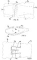
- FIG. 1 An in Fig. 1
- the rotor blade 1 of the rotor of a wind turbine, which is otherwise not shown, is shown in detail and has two rotor blade sections 2 and 3 in the example, one of which includes the blade root and the other the free blade end (blade root and end not visible).
- a connection area is formed between the rotor blade sections 2, 3.
- the rotor blade sections 2, 3 have a hollow, in Fig. 3
- Fig. 1 shows the respective negative pressure sides in plan view.
- Spar 7 shown in cross section has a double-T profile with belt parts 8.9 parallel to the wall shells 5.6.
- the belt parts 8, 9 each engage in recesses in the wall shells 5, 6 and are glued to the wall shells 5, 6 over the entire surface.
- two webs 10 form the vertical limb of the double-T profile.
- the belt parts 8, 9 are widened towards the connecting end of the rotor blade sections 2, 3 and, if necessary, thickened in sections.
- the widened strap parts 8, 9 connected to the wall shells 5, 6 each form an abutment surface 11 or 12.
- bores 13 open, which are arranged according to a line running along the contour of the wall shells 5, 6, such as Fig. 2 reveals.
- the relevant bores 13 of the rotor blade section 2 lie opposite the corresponding bores 13 of the rotor blade section 3, axially aligned with them.
- a pin connecting element 14 engages in each of the mutually aligned bores 13, in the example shown in each case with approximately half its length.
- the pin connecting elements 14 are firmly fixed in the bores 13.
- both the pin connection elements 14 and all shown parts of the rotor blade sections 2, 3 are preferably made of fiber composite material, including carbon fiber composite material, in particular the spar 7 including widenings being designed as a fiber composite structure.
- FIGS. 4 and 5 schematically illustrated pin connecting elements 14 can have a thickening according to FIGS. 4 and 5 exhibit.
- the thickening 15, which is arranged in the longitudinal center of the pin connecting element 14 in the example, is in the example arranged symmetrically to the joint between the interconnected rotor blade sections 2, 3.
- the pin connecting element 14 is fixed in the bores 13, which are opposite one another in mirror-inverted fashion, by means of a hardened adhesive layer 16.
- an adhesive layer 17 is also formed between the abutment surfaces 11, 12, in which the bores 13, opposite one another in mirror image, open for receiving the pin connecting elements 14.
- the thickening 15 of the in Fig. 4 The pin connecting element 14 shown in the example is formed by a sleeve 19 pushed onto a pin base body 18 and fixed by gluing.
- the sleeve 19 has a conical taper 20 at each of its ends.
- the cross-sectional area of the pin connecting element 14 is continuously circular.
- the bore 13 widened in accordance with the thickening 15 can advantageously be produced in a single operation with the aid of a correspondingly shaped drilling tool.
- a channel 22 leading to the outside of the rotor blade section 2, 3 through which the adhesive compound can be pressed into a gap between the pin connecting element 14 and the wall of the bore 13 can open into the bore 13 receiving the pin connecting element 14.
- the channel 22 expediently opens at the closed end of the bore 13.
- At the open end at least one control channel leading to the outside of the rotor blade section 2 or 3 can open into the bore 13.
- a groove 23 made in the abutment surface 11 or 12 is expediently formed as a control channel. It goes without saying that the channel 22 or the groove 23 can also open towards the inside of the rotor blade.
- Fig. 7 For example, four such grooves 23 can open into the bore 13 at points distributed over the circumference of the bore 13.
- Adhesive compound 16 emerging from the groove channels 23 indicates that the adhesive gap between the pin connecting element 14 and the bore wall is completely filled with adhesive.
- Spacers protruding radially from a carrier ring can be attached to the pin connection element 14, for example, which center the pin connection element 14 within the bore 13 and ensure a gap that is sufficient all round to accommodate adhesive.
- Figures 8 and 9 show an exemplary embodiment for an expansion area 21 of the belt part 8 or 9.
- the remaining area of the belt part which has a constant cross-sectional area, merges into an end section 25 with decreasing thickness.
- the decrease in thickness is achieved by progressively reducing the number of laminate layers, so-called scarfing.
- the shanked end section 25 is connected to an inverted shanked laminate structure 26, by means of which the belt part 8 or 9 increases both in thickness and in width up to an end area 27 having the abutment surface 11 or 12.
- placeholder fillings 29 for example made of foam or balsa.
- the end area 27 again has a scarf like the end section 25, i.e. its thickness decreases slightly towards the abutment surface 11 or 12.
- the width of the belt part 8 or 9 increases from 0.7 m to 1 m and the thickness from 23 mm to 100 mm.
- the widening area 21 could also be completely prefabricated and glued to the spar as a whole.
- peg-like connecting elements 14a which are connected in one piece to widened belt parts 8a and 9a of a spar 7a.
- the peg-like connecting elements 14a are flat in cross section and engage in slot-shaped receiving recesses 13a in correspondingly widened belt parts of a spar 7a 'of the rotor blade section 2a.
- the connecting elements 14a are anchored in the receiving recesses 13a by means of the previously introduced and cured adhesive mass.
- the peg-like connecting elements 14a which are flat in cross section, consist of laminate layer sections which protrude from the widened belt part, which is itself formed by laminate layers.
- the slot-shaped receiving recesses 13a are formed, for example, by cores which have been removed after the respective belt parts have been laminated.
- slot-shaped receiving recesses 13b are undercut and deformable peg-like connecting elements 14b engage in the receiving recesses for the purpose of introduction into the receiving recesses.
- the deformability of the connecting elements 14b results from a wedge-shaped incision 30 with a widening at the closed end. Compressible legs are formed by the incision 30 which expand again after the connecting element 14b has been inserted into the receiving recess 13b. How Fig. 12 can be seen, the wedge-shaped cutout is filled with hardened adhesive mass 16b.
Landscapes
- Engineering & Computer Science (AREA)
- Life Sciences & Earth Sciences (AREA)
- Sustainable Development (AREA)
- Sustainable Energy (AREA)
- Chemical & Material Sciences (AREA)
- Combustion & Propulsion (AREA)
- Mechanical Engineering (AREA)
- General Engineering & Computer Science (AREA)
- Wind Motors (AREA)
Applications Claiming Priority (2)
| Application Number | Priority Date | Filing Date | Title |
|---|---|---|---|
| DE102019128240 | 2019-10-18 | ||
| DE102019128487.2A DE102019128487A1 (de) | 2019-10-18 | 2019-10-22 | Verbindung zwischen Längssegmenten eines Rotorblattes des Rotors einer Windenergieanlage |
Publications (2)
| Publication Number | Publication Date |
|---|---|
| EP3808972A1 true EP3808972A1 (fr) | 2021-04-21 |
| EP3808972B1 EP3808972B1 (fr) | 2026-04-29 |
Family
ID=72840323
Family Applications (1)
| Application Number | Title | Priority Date | Filing Date |
|---|---|---|---|
| EP20201228.2A Active EP3808972B1 (fr) | 2019-10-18 | 2020-10-12 | Raccordement entre les segments longitudinaux d'une pale de rotor du rotor d'une éolienne |
Country Status (1)
| Country | Link |
|---|---|
| EP (1) | EP3808972B1 (fr) |
Cited By (2)
| Publication number | Priority date | Publication date | Assignee | Title |
|---|---|---|---|---|
| US20230364875A1 (en) * | 2021-09-10 | 2023-11-16 | Newtech Group Co., Ltd. | Modular wind turbine blade and manufacturing method thereof |
| EP4382742A4 (fr) * | 2021-08-06 | 2024-11-27 | Nabrawind Technologies, S.L. | Transition sur stratifiés en matériau composite pour pale modulaire |
Citations (9)
| Publication number | Priority date | Publication date | Assignee | Title |
|---|---|---|---|---|
| WO2010086297A2 (fr) * | 2009-01-27 | 2010-08-05 | Vestas Wind Systems A/S | Aube d'éolienne sectionnelle |
| EP1761702B1 (fr) | 2004-06-30 | 2011-11-23 | Vestas Wind Systems A/S | Ailettes d'eolienne constituees de deux sections distinctes |
| EP2740583A1 (fr) | 2012-12-04 | 2014-06-11 | Nordex Energy GmbH | Procédé de fabrication d'une pale de rotor d'éolienne avec un premier et un deuxième segment de pale et pale de rotor d'éolienne |
| EP2815861A1 (fr) * | 2013-06-18 | 2014-12-24 | Nordex Energy GmbH | Procédé et outil de formage pour la fabrication d'un segment pour une pale de rotor d'installation éolienne et segment |
| EP2881580A1 (fr) * | 2013-12-04 | 2015-06-10 | General Electric Company | Ensemble de longeron pour pale d'éolienne |
| EP2264310B1 (fr) | 2009-05-28 | 2016-04-20 | General Electric Company | Procédé d'assemblage de pale d'éolienne |
| EP3064768A1 (fr) * | 2015-03-04 | 2016-09-07 | Siemens Aktiengesellschaft | Procédé de fabrication de pale de rotor d'éolienne et procédé de montage de ladite pale |
| US9506452B2 (en) | 2013-08-28 | 2016-11-29 | General Electric Company | Method for installing a shear web insert within a segmented rotor blade assembly |
| WO2021018362A1 (fr) * | 2019-07-30 | 2021-02-04 | Vestas Wind Systems A/S | Raccord pour pale d'éolienne en deux parties |
-
2020
- 2020-10-12 EP EP20201228.2A patent/EP3808972B1/fr active Active
Patent Citations (9)
| Publication number | Priority date | Publication date | Assignee | Title |
|---|---|---|---|---|
| EP1761702B1 (fr) | 2004-06-30 | 2011-11-23 | Vestas Wind Systems A/S | Ailettes d'eolienne constituees de deux sections distinctes |
| WO2010086297A2 (fr) * | 2009-01-27 | 2010-08-05 | Vestas Wind Systems A/S | Aube d'éolienne sectionnelle |
| EP2264310B1 (fr) | 2009-05-28 | 2016-04-20 | General Electric Company | Procédé d'assemblage de pale d'éolienne |
| EP2740583A1 (fr) | 2012-12-04 | 2014-06-11 | Nordex Energy GmbH | Procédé de fabrication d'une pale de rotor d'éolienne avec un premier et un deuxième segment de pale et pale de rotor d'éolienne |
| EP2815861A1 (fr) * | 2013-06-18 | 2014-12-24 | Nordex Energy GmbH | Procédé et outil de formage pour la fabrication d'un segment pour une pale de rotor d'installation éolienne et segment |
| US9506452B2 (en) | 2013-08-28 | 2016-11-29 | General Electric Company | Method for installing a shear web insert within a segmented rotor blade assembly |
| EP2881580A1 (fr) * | 2013-12-04 | 2015-06-10 | General Electric Company | Ensemble de longeron pour pale d'éolienne |
| EP3064768A1 (fr) * | 2015-03-04 | 2016-09-07 | Siemens Aktiengesellschaft | Procédé de fabrication de pale de rotor d'éolienne et procédé de montage de ladite pale |
| WO2021018362A1 (fr) * | 2019-07-30 | 2021-02-04 | Vestas Wind Systems A/S | Raccord pour pale d'éolienne en deux parties |
Cited By (3)
| Publication number | Priority date | Publication date | Assignee | Title |
|---|---|---|---|---|
| EP4382742A4 (fr) * | 2021-08-06 | 2024-11-27 | Nabrawind Technologies, S.L. | Transition sur stratifiés en matériau composite pour pale modulaire |
| US20230364875A1 (en) * | 2021-09-10 | 2023-11-16 | Newtech Group Co., Ltd. | Modular wind turbine blade and manufacturing method thereof |
| US12311627B2 (en) * | 2021-09-10 | 2025-05-27 | Newtech Group Co., Ltd. | Modular wind turbine blade and manufacturing method thereof |
Also Published As
| Publication number | Publication date |
|---|---|
| EP3808972B1 (fr) | 2026-04-29 |
Similar Documents
| Publication | Publication Date | Title |
|---|---|---|
| EP3114348B1 (fr) | Procédé servant à fabriquer une pale de rotor d'une éolienne, pale de rotor et éolienne | |
| DE102011082664C5 (de) | Form zur Herstellung eines Steges und Steg für ein Rotorblatt einer Windenergieanlage | |
| DE102014221966B4 (de) | Verfahren zum Herstellen eines Rotorblatts einer Windenergieanlage | |
| DE3911691A1 (de) | Verbundbefestigung | |
| DE2451860A1 (de) | Rotorblatt aus kunststoffmaterial | |
| WO2004015265A1 (fr) | Procede de production d'une pale de rotor, pale de rotor et eolienne correspondantes | |
| EP2740583B1 (fr) | Procédé de fabrication d'une pale de rotor d'éolienne avec un premier et un deuxième segment de pale et pale de rotor d'éolienne | |
| DE102008007304A1 (de) | Rotorblatt für Windenergieanlagen | |
| DE102019128487A1 (de) | Verbindung zwischen Längssegmenten eines Rotorblattes des Rotors einer Windenergieanlage | |
| EP3808972A1 (fr) | Raccordement entre les segments longitudinaux d'une pale de rotor du rotor d'une éolienne | |
| WO2016113041A1 (fr) | Procédé de montage d'aubes mobiles sur un disque de rotor ainsi que dispositif de serrage pour la mise en œuvre d'un tel procédé | |
| EP3551438B1 (fr) | Membrure de bord de fuite d'une pale de rotor d'une installation éolienne, pale de rotor et procédé de fabrication d'une membrure de bord de fuite | |
| DE102008060705A1 (de) | Horizontal geteiltes Strömungsmaschinengehäuse | |
| EP1552149A1 (fr) | Stator pour pompe a vis sans fin excentrique | |
| DE19543516A1 (de) | Transportelement für flächiges Gut | |
| EP3015702B1 (fr) | Pale de rotor pour une eolienne et procede de fabrication d'une pale de rotor | |
| EP3994351A1 (fr) | Pale de rotor pour une éolienne, segment de pale de rotor, éolienne et procédé pour la fabrication d'une pale de rotor | |
| DE2731761B2 (de) | Hohlraumbefestigung | |
| DE60101675T2 (de) | Verstärktes verbindungselement | |
| EP4524406B1 (fr) | Cheville adhésive pour un panneau léger, panneau léger et procédé de montage d'une cheville adhésive dans un panneau léger | |
| DE3437942C2 (de) | Hubschrauber-Rotorblatt | |
| EP3887670A1 (fr) | Procédé d'introduction d'une courroie de pale de rotor dans une coque de pale de rotor, moule de courroie, pale de rotor ainsi qu'éolienne | |
| DE102018133523B3 (de) | Lastrahmen, Prüfstandsystem und Verfahren zum Einspannen eines Prüfkörpers | |
| DE10249591A1 (de) | Nachträglich einlaminierbare Krafteinleitung aus Faserverbundwerkstoff für stabförmige Faserverbundstrukturen | |
| DE102006001514B4 (de) | Segment eines Abbeerzylinders und Abbeerzylinder |
Legal Events
| Date | Code | Title | Description |
|---|---|---|---|
| PUAI | Public reference made under article 153(3) epc to a published international application that has entered the european phase |
Free format text: ORIGINAL CODE: 0009012 |
|
| STAA | Information on the status of an ep patent application or granted ep patent |
Free format text: STATUS: THE APPLICATION HAS BEEN PUBLISHED |
|
| AK | Designated contracting states |
Kind code of ref document: A1 Designated state(s): AL AT BE BG CH CY CZ DE DK EE ES FI FR GB GR HR HU IE IS IT LI LT LU LV MC MK MT NL NO PL PT RO RS SE SI SK SM TR |
|
| AX | Request for extension of the european patent |
Extension state: BA ME |
|
| STAA | Information on the status of an ep patent application or granted ep patent |
Free format text: STATUS: REQUEST FOR EXAMINATION WAS MADE |
|
| 17P | Request for examination filed |
Effective date: 20211020 |
|
| RBV | Designated contracting states (corrected) |
Designated state(s): AL AT BE BG CH CY CZ DE DK EE ES FI FR GB GR HR HU IE IS IT LI LT LU LV MC MK MT NL NO PL PT RO RS SE SI SK SM TR |
|
| STAA | Information on the status of an ep patent application or granted ep patent |
Free format text: STATUS: EXAMINATION IS IN PROGRESS |
|
| 17Q | First examination report despatched |
Effective date: 20220923 |
|
| GRAP | Despatch of communication of intention to grant a patent |
Free format text: ORIGINAL CODE: EPIDOSNIGR1 |
|
| STAA | Information on the status of an ep patent application or granted ep patent |
Free format text: STATUS: GRANT OF PATENT IS INTENDED |
|
| RIC1 | Information provided on ipc code assigned before grant |
Ipc: F03D 1/06 20060101AFI20251119BHEP |
|
| INTG | Intention to grant announced |
Effective date: 20251210 |
|
| GRAS | Grant fee paid |
Free format text: ORIGINAL CODE: EPIDOSNIGR3 |
|
| GRAA | (expected) grant |
Free format text: ORIGINAL CODE: 0009210 |
|
| STAA | Information on the status of an ep patent application or granted ep patent |
Free format text: STATUS: THE PATENT HAS BEEN GRANTED |