EP3808975B1 - Système et procédé de verrouillage d'un rotor d'une éolienne pendant la maintenance étendue - Google Patents
Système et procédé de verrouillage d'un rotor d'une éolienne pendant la maintenance étendue Download PDFInfo
- Publication number
- EP3808975B1 EP3808975B1 EP20202056.6A EP20202056A EP3808975B1 EP 3808975 B1 EP3808975 B1 EP 3808975B1 EP 20202056 A EP20202056 A EP 20202056A EP 3808975 B1 EP3808975 B1 EP 3808975B1
- Authority
- EP
- European Patent Office
- Prior art keywords
- rotor lock
- rotor
- pin shaft
- removable
- wind turbine
- Prior art date
- Legal status (The legal status is an assumption and is not a legal conclusion. Google has not performed a legal analysis and makes no representation as to the accuracy of the status listed.)
- Active
Links
Images



Classifications
-
- F—MECHANICAL ENGINEERING; LIGHTING; HEATING; WEAPONS; BLASTING
- F03—MACHINES OR ENGINES FOR LIQUIDS; WIND, SPRING, OR WEIGHT MOTORS; PRODUCING MECHANICAL POWER OR A REACTIVE PROPULSIVE THRUST, NOT OTHERWISE PROVIDED FOR
- F03D—WIND MOTORS
- F03D80/00—Details, components or accessories not provided for in groups F03D1/00 - F03D17/00
- F03D80/50—Maintenance or repair
- F03D80/505—Locking rotors in position
-
- F—MECHANICAL ENGINEERING; LIGHTING; HEATING; WEAPONS; BLASTING
- F03—MACHINES OR ENGINES FOR LIQUIDS; WIND, SPRING, OR WEIGHT MOTORS; PRODUCING MECHANICAL POWER OR A REACTIVE PROPULSIVE THRUST, NOT OTHERWISE PROVIDED FOR
- F03D—WIND MOTORS
- F03D80/00—Details, components or accessories not provided for in groups F03D1/00 - F03D17/00
- F03D80/50—Maintenance or repair
-
- F—MECHANICAL ENGINEERING; LIGHTING; HEATING; WEAPONS; BLASTING
- F03—MACHINES OR ENGINES FOR LIQUIDS; WIND, SPRING, OR WEIGHT MOTORS; PRODUCING MECHANICAL POWER OR A REACTIVE PROPULSIVE THRUST, NOT OTHERWISE PROVIDED FOR
- F03D—WIND MOTORS
- F03D7/00—Controlling wind motors
- F03D7/02—Controlling wind motors the wind motors having rotation axis substantially parallel to the air flow entering the rotor
- F03D7/0264—Controlling wind motors the wind motors having rotation axis substantially parallel to the air flow entering the rotor for stopping; controlling in emergency situations
- F03D7/0268—Parking or storm protection
-
- F—MECHANICAL ENGINEERING; LIGHTING; HEATING; WEAPONS; BLASTING
- F03—MACHINES OR ENGINES FOR LIQUIDS; WIND, SPRING, OR WEIGHT MOTORS; PRODUCING MECHANICAL POWER OR A REACTIVE PROPULSIVE THRUST, NOT OTHERWISE PROVIDED FOR
- F03D—WIND MOTORS
- F03D80/00—Details, components or accessories not provided for in groups F03D1/00 - F03D17/00
- F03D80/70—Bearing or lubricating arrangements
-
- F—MECHANICAL ENGINEERING; LIGHTING; HEATING; WEAPONS; BLASTING
- F05—INDEXING SCHEMES RELATING TO ENGINES OR PUMPS IN VARIOUS SUBCLASSES OF CLASSES F01-F04
- F05B—INDEXING SCHEME RELATING TO WIND, SPRING, WEIGHT, INERTIA OR LIKE MOTORS, TO MACHINES OR ENGINES FOR LIQUIDS COVERED BY SUBCLASSES F03B, F03D AND F03G
- F05B2230/00—Manufacture
- F05B2230/80—Repairing, retrofitting or upgrading methods
-
- F—MECHANICAL ENGINEERING; LIGHTING; HEATING; WEAPONS; BLASTING
- F05—INDEXING SCHEMES RELATING TO ENGINES OR PUMPS IN VARIOUS SUBCLASSES OF CLASSES F01-F04
- F05B—INDEXING SCHEME RELATING TO WIND, SPRING, WEIGHT, INERTIA OR LIKE MOTORS, TO MACHINES OR ENGINES FOR LIQUIDS COVERED BY SUBCLASSES F03B, F03D AND F03G
- F05B2240/00—Components
- F05B2240/20—Rotors
- F05B2240/21—Rotors for wind turbines
-
- F—MECHANICAL ENGINEERING; LIGHTING; HEATING; WEAPONS; BLASTING
- F05—INDEXING SCHEMES RELATING TO ENGINES OR PUMPS IN VARIOUS SUBCLASSES OF CLASSES F01-F04
- F05B—INDEXING SCHEME RELATING TO WIND, SPRING, WEIGHT, INERTIA OR LIKE MOTORS, TO MACHINES OR ENGINES FOR LIQUIDS COVERED BY SUBCLASSES F03B, F03D AND F03G
- F05B2240/00—Components
- F05B2240/50—Bearings
-
- F—MECHANICAL ENGINEERING; LIGHTING; HEATING; WEAPONS; BLASTING
- F05—INDEXING SCHEMES RELATING TO ENGINES OR PUMPS IN VARIOUS SUBCLASSES OF CLASSES F01-F04
- F05B—INDEXING SCHEME RELATING TO WIND, SPRING, WEIGHT, INERTIA OR LIKE MOTORS, TO MACHINES OR ENGINES FOR LIQUIDS COVERED BY SUBCLASSES F03B, F03D AND F03G
- F05B2260/00—Function
- F05B2260/30—Retaining components in desired mutual position
- F05B2260/31—Locking rotor in position
-
- Y—GENERAL TAGGING OF NEW TECHNOLOGICAL DEVELOPMENTS; GENERAL TAGGING OF CROSS-SECTIONAL TECHNOLOGIES SPANNING OVER SEVERAL SECTIONS OF THE IPC; TECHNICAL SUBJECTS COVERED BY FORMER USPC CROSS-REFERENCE ART COLLECTIONS [XRACs] AND DIGESTS
- Y02—TECHNOLOGIES OR APPLICATIONS FOR MITIGATION OR ADAPTATION AGAINST CLIMATE CHANGE
- Y02E—REDUCTION OF GREENHOUSE GAS [GHG] EMISSIONS, RELATED TO ENERGY GENERATION, TRANSMISSION OR DISTRIBUTION
- Y02E10/00—Energy generation through renewable energy sources
- Y02E10/70—Wind energy
- Y02E10/72—Wind turbines with rotation axis in wind direction
-
- Y—GENERAL TAGGING OF NEW TECHNOLOGICAL DEVELOPMENTS; GENERAL TAGGING OF CROSS-SECTIONAL TECHNOLOGIES SPANNING OVER SEVERAL SECTIONS OF THE IPC; TECHNICAL SUBJECTS COVERED BY FORMER USPC CROSS-REFERENCE ART COLLECTIONS [XRACs] AND DIGESTS
- Y02—TECHNOLOGIES OR APPLICATIONS FOR MITIGATION OR ADAPTATION AGAINST CLIMATE CHANGE
- Y02P—CLIMATE CHANGE MITIGATION TECHNOLOGIES IN THE PRODUCTION OR PROCESSING OF GOODS
- Y02P70/00—Climate change mitigation technologies in the production process for final industrial or consumer products
- Y02P70/50—Manufacturing or production processes characterised by the final manufactured product
Definitions
- the present disclosure relates in general to wind turbines, and more particularly to systems and methods for locking a rotor of a wind turbine during extended maintenance operations.
- a modem wind turbine typically includes a tower, a generator, a gearbox, a nacelle, and one or more rotor blades.
- the nacelle includes a rotor assembly coupled to the gearbox and to the generator.
- the rotor assembly and the gearbox are mounted on a bedplate support frame located within the nacelle. More specifically, in many wind turbines, the gearbox is mounted to the bedplate via one or more torque arms or arms.
- the one or more rotor blades capture kinetic energy of wind using known airfoil principles.
- the rotor blades transmit the kinetic energy in the form of rotational energy so as to turn a shaft coupling the rotor blades to a gearbox, or if a gearbox is not used, directly to the generator.
- the generator then converts the mechanical energy to electrical energy that may be deployed to a utility grid.
- the majority of commercially available wind turbines utilize multi-stage geared drivetrains to connect the turbine blades to electrical generators.
- the wind turns the rotor blades, which spin a low speed shaft, i.e. the main shaft.
- the main shaft is coupled to an input shaft of the gearbox, which has a higher speed output shaft connected to the generator.
- the geared drivetrain aims to increase the velocity of the mechanical motion.
- the gearbox and the generator are typically supported by one or more bearings and mounted to a bedplate member via one or more torque arms or supports.
- the low-speed rotor lock is designed to withstand an anticipated load of the rotor in response to winds up to a certain threshold.
- the low-speed rotor lock may, generally, only be employed for such a length of time as it is possible to predict, with a reasonable degree of certainty, that the winds will not exceed the threshold.
- Such a time period is usually limited to a few hours. However, certain maintenance procedures cannot be accomplished within this time frame.
- KR 100 821 704 B1 relates to a rotor locking device for temporarily fixing the rotor to prevent movement of the rotor constituting the wind power generator during installation, movement, or maintenance work of the wind power generator.
- a rotor lock assembly for locking a rotor of a wind turbine according to independent claim 1.
- a rotor lock assembly includes at least one removable rotor lock.
- the removable rotor lock(s) includes a housing including an opening and a mounting portion. The opening extends from a first end to a second end thereof.
- the mounting portion is adapted for mounting to a removable rotor lock mounting point.
- the removable rotor(s) includes a pin shaft positioned within the opening.
- the pin shaft includes a proximal end and a distal end. The pin shaft is movable within the opening such that the distal end moves toward and engages the rotor lock plate of the rotor.
- the removable rotor lock(s) also includes a locking mechanism for locking the pin shaft in place.
- the rotor lock assembly may also include a plurality of fasteners for securing the mounting portion of the housing to the bearing housing through a plurality of fastener openings of the mounting portion.
- the pin shaft may engage the rotor lock plate via a through hole configured therethrough. The through hole may define an axis parallel to and offset from a main shaft of the rotor.
- the rotor lock assembly may also include an alignment system operably coupled to the pin shaft so as to align the pin shaft with the through hole of the rotor lock plate.
- the removable rotor lock(s) may include a first removable rotor lock and a second removable rotor lock.
- the first removable rotor lock may be coupled to a first quadrant of the bearing housing, and the second removable rotor lock may be coupled to a second, adjacent quadrant of the bearing housing.
- the housing may include a bushing element positioned within the opening and a bushing securing mechanism oriented to engage a corresponding feature of the bushing element and secure the bushing element within the opening.
- the pin shaft may be movable within the bushing element via at least one of an axial movement or a rotational movement.
- the pin shaft may be moved by at least one of a direct-manual engagement system, a hydraulic engagement system, a geared engagement system, or a motorized engagement system operably coupled to the pin shaft.
- the proximal end of the pin shaft engages the locking mechanism.
- the distal end of the pin shaft may include a tapered cross-sectional profile.
- the housing may also include at least one attachment location for providing a lifting point for lifting the rotor lock assembly uptower.
- the present disclosure is directed to a method for performing a maintenance and/or repair procedure on a rotor component of a wind turbine according to the independent method claim.
- a method includes coupling the removable rotor lock(s) to a main bearing housing. The method includes preventing rotation of the rotor and advancing an integral low-speed rotor lock of the wind turbine so as to engage a first corresponding feature of the rotor lock plate. The method includes advancing a pin shaft of the at least one removable rotor lock to an advanced position so as to engage a second corresponding feature of the rotor lock plate. The method also includes securing the pin shaft in the advanced position through the engagement of the locking mechanism.
- the method for performing a maintenance and/or repair procedure on a rotor component of a wind turbine may also include aligning the pin shaft with the corresponding feature of the rotor lock plate via an alignment system operably coupled to the pin shaft.
- advancing the pin shaft may include advancing the pin shaft via at least one of a direct-manual engagement system, a hydraulic engagement system, a geared engagement system, or a motorized engagement system operably coupled to the pin shaft.
- the method may include coupling first and second rotor lock(s) to a first quadrant of the bearing housing and an adjacent, second quadrant of the main bearing housing, respectively.
- the method may also include performing the maintenance procedure on an assembled nacelle, uptower.
- the method may include hoisting the first and second removable rotor locks through an access hatch located on an underside of the nacelle up tower.
- the wind turbine repair system may include a rotor lock plate circumferentially mounted to a rotor shaft of the wind turbine.
- the rotor lock plate may define a plurality of openings, which have an axis parallel to and offset from the rotor shaft.
- the wind turbine repair system may include a low-speed rotor lock coupled to a bedplate support frame perpendicular to the rotor lock plate, a bearing housing, and at least one removable rotor lock mounted to the bearing housing.
- the removable rotor lock may include a housing having an opening and a mounting portion. The opening may extend from a first end to a second end thereof.
- the mounting portion may be adapted for mounting to a bearing housing adjacent to a rotor lock plate of the rotor.
- the removable rotor lock may also include a pin shaft positioned within the opening.
- the pin shaft may include a proximal end and a distal end.
- the pin shaft may be movable within the opening such that the distal end moves toward and engages the rotor lock plate of the rotor.
- the removable rotor lock may also include a locking mechanism for locking the pin shaft in place.
- the present disclosure is directed to a rotor lock assembly for locking a rotor of a wind turbine during an extended maintenance operation.
- the rotor lock assembly includes a removable rotor lock(s).
- the removable rotor lock(s) includes may a housing, a bushing element, a pin shaft, and a locking mechanism.
- the housing has an opening extending from a first end to a second end and a mounting portion.
- the mounting portion is adapted or formed for mounting to a corresponding attachment location on the outer surface of the main bearing housing, which is adjacent to a rotor lock plate of the rotor.
- the bushing element is positioned within the opening of the housing and the pin shaft is positioned within the bushing element.
- the pin shaft has a proximal end and a distal end.
- the pin shaft is movable within the bushing element such that a force applied to the pin shaft may cause the pin shaft to move towards and engage the rotor lock plate of the rotor.
- the pin shaft may be locked in this engaged position by an attached locking mechanism.
- the removable rotor lock(s) may be sized so as to share a working load with an integral low-speed rotor lock which is coupled to a bedplate support frame.
- the shared working load of the removable rotor lock(s) and the low-speed rotor lock may be sufficient to withstand the forces generated by a wind in excess of the forecasted a speed during an extended maintenance period.
- a maintenance and/or repair procedure may be performed on a component of the wind turbine by coupling the removable rotor lock(s) to the main bearing housing of the wind turbine.
- the rotation of the rotor in response to the force of the wind, may be stopped and a built-in, or integral, low-speed rotor lock of the wind turbine may be advanced so as to engage a feature, such as a hole or a depression, of the rotor lock plate.
- the pin shaft of the removable rotor lock(s) may be advanced so as to engage a second feature of the rotor lock plate.
- the pin shaft may be secured in the advanced position through the engagement of a locking mechanism. With the rotor so secured, an extended maintenance operation may be performed on the wind turbine while the wind turbine is potentially exposed to a broader range of wind speeds.
- FIG. 1 illustrates a perspective view of one embodiment of a wind turbine 100 according to the present disclosure.
- the wind turbine 100 generally includes a tower 102 extending from a support surface 104, a nacelle 106, which includes an outer shell 160, mounted on the tower 102, and a rotor 108 coupled to the nacelle 106.
- the rotor 108 includes a rotatable hub 110 and at least one rotor blade 112 coupled to and extending outwardly from the hub 110.
- the rotor 108 includes three rotor blades 112.
- the rotor 108 may include more or less than three rotor blades 112.
- Each rotor blade 112 may be spaced about the hub 110 to facilitate rotating the rotor 108 to enable kinetic energy to be transferred from the wind into usable mechanical energy, and subsequently, electrical energy.
- the hub 110 may be rotatably coupled to an electric generator 118 ( FIG. 2 ) positioned within the nacelle 106 to permit electrical energy to be produced.
- the wind turbine 100 may also include a wind turbine controller 114 centralized within the nacelle 106.
- the controller 114 may be located within any other component of the wind turbine 100 or at a location outside the wind turbine. Further, the controller 114 may be communicatively coupled to any number of the components of the wind turbine 100 in order to control the components.
- the controller 114 may include a computer or other suitable processing unit.
- the controller 114 may include suitable computer-readable instructions that, when implemented, configure the controller 114 to perform various different functions, such as receiving, transmitting and/or executing wind turbine control signals.
- the generator 118 may be coupled to the rotor 108 for producing electrical power from the rotational energy generated by the rotor 108.
- the rotor 108 may include a rotor shaft 122 coupled to the hub 110 for rotation therewith.
- the rotor shaft 122 may be rotatably supported by a main bearing 144.
- the rotor shaft 122 may, in turn, be rotatably coupled to a generator shaft 124 of the generator 118 through a gearbox 126 connected to a bedplate support frame 136 by one or more torque arms 142.
- the rotor shaft 122 may provide a low speed, high torque input to the gearbox 126 in response to rotation of the rotor blades 112 and the hub 110.
- the gearbox 122 may then be configured to convert the low speed, high torque input to a high speed, low torque output to drive the generator shaft 124 and, thus, the generator 118.
- Each rotor blade 112 may also include a pitch adjustment mechanism 120 configured to rotate each rotor blade 112 about its pitch axis 116.
- each pitch adjustment mechanism 120 may include a pitch drive motor 128 (e.g., any suitable electric, hydraulic, or pneumatic motor), a pitch drive gearbox 130, and a pitch drive pinion 132.
- the pitch drive motor 128 may be coupled to the pitch drive gearbox 130 so that the pitch drive motor 128 imparts mechanical force to the pitch drive gearbox 130.
- the pitch drive gearbox 130 may be coupled to the pitch drive pinion 132 for rotation therewith.
- the pitch drive pinion 132 may, in turn, be in rotational engagement with a pitch bearing 134 coupled between the hub 110 and a corresponding rotor blade 112 such that rotation of the pitch drive pinion 132 causes rotation of the pitch bearing 134.
- rotation of the pitch drive motor 128 drives the pitch drive gearbox 130 and the pitch drive pinion 132, thereby rotating the pitch bearing 134 and the rotor blade 112 about the pitch axis 116.
- the wind turbine 100 may include one or more yaw drive mechanisms 138 communicatively coupled to the controller 114, with each yaw drive mechanism(s) 138 being configured to change the angle of the nacelle 106 relative to the wind (e.g., by engaging a yaw bearing 140 of the wind turbine 100).
- the main bearing 144 may generally correspond to a tapered roller bearing but may be any suitable bearing, including for example, a spherical roller bearing, a ball bearing, or any other suitable bearing.
- the main bearing 144 may be secured in place via a bearing housing 146.
- the main bearing 144 may also be mounted to the bedplate support member 136 of the nacelle 106 via one or more torque supports 148.
- the wind turbine 100 may be outfitted with a rotor lock plate 150.
- the rotor lock plate 150 may encircle the rotor shaft 122 of the wind turbine 100.
- the rotor lock plate 150 may include a plurality of features 152 which may be engaged in order to secure the rotor 108 and prevent rotation of the rotor 108 in response to a wind load.
- the features 152 may be a plurality of through holes 154 defined by the rotor lock plate 150.
- the through holes 154 may define an axis (H A ) parallel to and offset from the main shaft 122 of the rotor 108.
- the features 152 may, for example, be depressions, grooves, ridges, teeth, or high-friction regions which may be engaged so as to secure the rotor 108.
- the wind turbine 100 may also be outfitted with a low-speed rotor lock 156.
- the low-speed rotor lock 156 may be built into, and be integral with, the bedplate support frame 136.
- the low-speed rotor lock 156 may include a low-speed rotor lock pin 158 which may be advanced to engage a corresponding feature 152 of the rotor lock plate 150.
- the low-speed rotor lock 156 may be sized so as to resist a force developed by winds up to a first wind threshold.
- FIGS. 3 and 4 side and rear views of a rotor lock assembly 200 in accordance with an embodiment of the present disclosure are illustrated.
- the rotor lock assembly 200 may lock a rotor 108 of a wind turbine 100 so as to facilitate maintenance operations during a period of time wherein the possibility exists to encounter winds in excess of the first wind threshold.
- the rotor lock assembly 200 may, in accordance with aspects of the present disclosure, include the removable rotor lock(s) 202. More specifically, as shown, the removable rotor lock(s) 202 may be coupled to a quadrant of the bearing housing 146 adjacent to the rotor lock plate 150. In an embodiment, as shown in FIG.
- the removable rotor lock(s) 202 may include a housing 204, a bushing element 206 a pin shaft 208 and a locking mechanism 210. It should be appreciated that in at least one embodiment, each rotor lock 202 may include a single pin shaft 208, with the housing 204 being sized to accommodate the single pin shaft 208 positioned within the bushing element 206.
- the rotor lock assembly 200 may include at least a first removable rotor lock 212 and a second removable lock 214.
- the first removable rotor lock 212 may be coupled to a first quadrant of the bearing housing 146.
- the second removable rotor lock 214 may be coupled to a second quadrant of the bearing housing 146 adjacent to the first quadrant.
- the removable rotor locks 202 work in conjunction with the low-speed rotor lock 156 to resist, a wind load, which includes a 15% safety margin.
- the various rotor locks may be subjected to differing portions of the wind load.
- the low-speed rotor lock 156 may be configured to resist up to 50% of the anticipated wind load, while a pair of removable rotor locks may each be configured to resist up to 25% of the anticipated wind load.
- the low-speed rotor lock 156 may be configured to resist up to 70% of the anticipated wind load, while the first removable rotor lock 212 may be configured to resist up to 20% of the anticipated wind load and the second removable rotor lock 214 may be configured to resist up to 10% of the anticipated wind load.
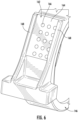
- FIGS. 5A and 5B illustrate a perspective view and an exploded perspective view of the rotor lock(s) 202 according to aspects of the present disclosure.
- the rotor lock(s) 202 may include a housing 204.
- the housing 204 may include an opening 216.
- the opening 216 may extend from a first end 220 to a second end 222.
- the housing 204 may also include a mounting portion 218.
- the mounting portion 218 may be adapted for mounting to the bearing housing 146 adjacent to the rotor lock plate 150 of the rotor 108. In an embodiment, such as depicted in FIG.
- the housing 204 may have a rounded-triangular cross-sectional shape wherein the housing radially tapers from a maximal width at the mounting portion 218.
- the mounting portion 218 may have a surface profile corresponding with a portion of a main bearing housing 146.
- the mounting portion 218 may define a plurality of fastener openings 224.
- a plurality of fasteners 226 may be inserted through the plurality of fastener openings 224 so as to secure the mounting portion 218, and thus the removable rotor lock(s) 202, to the bearing housing 146.
- the plurality of fasteners 226 may include screws, bolts, studs and nuts, or removable rivets.
- the removable rotor lock(s) 202 may be coupled to the bearing housing 146 by any suitable means.
- the rotor lock(s) 202 may be coupled to the bearing housing by adhering, fusing, welding, or other mechanical means such as a dovetail slot.
- the plurality of fastener openings 224 may be omitted from the mounting portion 218.
- the housing 204 may be equipped with at least one attachment location 228.
- the attachment location(s) 228 may be coupled to the housing 204.
- the attachment location(s) 228 may be a hoist ring, a pad eye, a lifting eye, an eye nut, or an eye bolt.
- the attachment location(s) 228 may include a protrusion, a recess, or a combination thereof integrally formed with the housing 204.
- the attachment location(s) 228 may provide a lifting point for lifting the relocatable rotor lock(s) 202 uptower.
- the housing 204 may be sized so as to have a lifting footprint which permits the housing 204 to be hoisted through an access hatch located on an underside of nacelle 106 up tower. Additionally, the housing 204 may be sized so as to permit the movement of the housing 204 from the access hatch to the bearing housing 146 without necessitating the removal of the outer shell 160 or the employment of a ground crane.
- multiple rotor locks 202 may facilitate securing the rotor lock plate 150 with multiple pin shafts 208 in situations where a single housing containing multiple pins may not be emplaced without removing the outer shell 160.
- the bearing housing 146 may include a removable rotor lock mounting point 162.
- the removable rotor lock mounting point 162 may include a planar surface 164 defining a plurality of fastener openings 166.
- the plurality of fastener openings 166 may be configured to couple the removable rotor lock(s) 202 to mounting point 162 via a plurality of fasteners 226 inserted through a plurality of fastener openings 224 of the mounting portion 218.
- the planar surface 164 having a long axis oriented perpendicular to the rotor shaft 122.
- the removable rotor lock mounting point 162 includes a pair of mounting ridges 168 oriented perpendicular to the rotor shaft 122 with the planar surface 164 disposed between the pair of mounting ridges 168.
- the planar surface 164 may be a curved surface formed so as to receive or be received by the mounting portion 218.
- the rotor lock(s) 202 may include the bushing element 206.
- the bushing element 206 may be positioned within the opening 216.
- the bushing element 206 may have a first portion 230 which may be inserted into the housing 204.
- the bushing element 206 may also have a second portion 232, which may extend outward from the opening second end 220.
- the bushing element 206 may include a securing feature 234.
- the securing feature 234 may be configured as a protrusion or a recess, which may be engaged by a bushing securing mechanism 236 coupled to the housing 204.
- the bushing securing mechanism 236 may secure the bushing element 206 within the opening 216 of the housing 204.
- the bushing element 206 may be a unitary body. Alternatively, the bushing element 206 may include multiple segments. For example, the first portion 230 may be a first segment, while the second portion 232 may be second segment. In an additional example, the bushing element 206 may be divided by a vertical plane so as to create a first half and a second half.
- the rotor lock(s) 202 may include the pin shaft 208.
- the pin shaft 208 may be positioned within the bushing element 206.
- the pin shaft 208 may include a proximal end 238 and a distal end 240.
- the pin shaft 208 may be movable within the bushing element 206.
- the distal end 240 may advance or move toward and engage the rotor lock plate 150 of the rotor 108.
- the proximal end 238 may be formed with a feature which may be engaged by the locking mechanism 210 coupled to at least one of the bushing element 206 or the housing 204 in order to secure the pin shaft 208 in a forward or engaged position.
- the locking mechanism 210 may include a lockout-tagout element which may prevent an unauthorized disengagement of the pin shaft 208. It should be appreciated that in at least one embodiment, the engagement of the rotor lock plate 150 may be facilitated by an alignment system operably coupled to the pin shaft 208, which may be configured to align the pin shaft 208 with the through hole 154 of the rotor lock plate 150.
- the pin shaft 208 may be movable within the bushing element 206 via at least one of an axial movement or a rotational movement along the axis (H A ).
- the movement of the pin shaft 208 may be motivated by an engagement system 242.
- the engagement system 242 may be at least one of a direct-manual engagement system, a hydraulic engagement system, a geared engagement system, or a motorized engagement system, which is operably coupled to the pin shaft 208.
- a direct-manual engagement system may involve the direct application, upon an engagement protrusion 244, of a force, by a technician in order to slide the pin shaft 208 in an axial direction.
- the force applied by the technician may cause the pin shaft 208 and/or the bushing element 206 to rotate in response to a plurality of threads and advance or be retracted.
- a tool may be employed to turn a crank, which may be coupled to a gearing system configured to move the pin shaft 208 within the bushing element 206.
- the distal end 240 of the pin shaft 208 may be relieved so as to facilitate the insertion and/or extraction of the pin shaft 208 from the rotor lock plate 150.
- the distal end 240 of the pin shaft 208 may have a tapered cross-sectional profile.
- the tapered cross-sectional profile of the distal end 240 may include, for example, an ogive, a chamfered, or a rounded cross-sectional profile.
- FIG. 7 a flow diagram of one embodiment of a method 300 for performing a maintenance and/or repair procedure on a component of a wind turbine is illustrated.
- the method 300 may be implemented using, for instance, the rotor lock assembly 200 discussed above with reference to FIGS. 3-5B .
- FIG. 6 depicts steps performed in a particular order for purposes of illustration and discussion. Those of ordinary skill in the art, using the disclosures provided herein, will understand that various steps of the method 300 or any of the other methods disclosed herein may be adapted, modified, rearranged, performed simultaneously or modified in various ways without deviating from the scope of the present disclosure.
- the method 300 includes coupling at least one removable rotor lock to a main bearing housing.
- the method 300 includes preventing rotation of the rotor, and at (306) advancing a built-in low-speed rotor lock of the wind turbine so as to engage a first corresponding feature of a rotor lock plate.
- the method 300 includes advancing a pin shaft of the at least one removable rotor lock to an advanced position so as to engage a second corresponding feature of the rotor lock plate.
- the method 300 includes securing the pin shaft in the advanced position through the engagement of a locking mechanism.
- the method (300) may also include aligning the pin shaft with the corresponding feature of the rotor lock plate via an alignment system operably coupled to the pin shaft. Further, advancing the pin shaft may include advancing the pin shaft via an engagement system operably coupled to the pin shaft. In another embodiment, the method (300) may include coupling a second rotor lock to the main bearing housing.
- the method of features at least one removable rotor lock comprises a first removable rotor lock coupled to a first quadrant of the bearing housing, the method further comprising: coupling a second removable rotor lock to an adjacent quadrant of the main bearing housing.
- the method further comprising: performing the maintenance procedure on an assembled nacelle, up tower.
- the method further comprising: hoisting the first and second removable rotor locks through an access hatch located on an underside of the nacelle up tower.
- a wind turbine repair system comprising: a rotor lock plate circumferentially mounted to a rotor shaft of the wind turbine, the rotor lock plate defining a plurality of openings, each of the plurality of openings having an axis parallel to and offset from the rotor shaft; a low-speed rotor lock coupled to a bedplate support frame perpendicular to the rotor lock plate; a bearing housing; and, a removable rotor lock mounted to the bearing housing, the removable rotor lock comprising: a housing comprising an opening and a mounting portion, the opening extending from a first end to a second end thereof, the mounting portion adapted for mounting to a bearing housing adjacent to a rotor lock plate of the rotor, a pin shaft positioned within the opening, the pin shaft comprising a proximal end and a distal end, the pin shaft being movable within the opening such that the distal end moves toward and engages the rotor lock plate of the rotor, and
- the wind turbine repair system of features a bearing housing further comprises a removable rotor lock mounting point, the removable rotor lock mounting point comprising: a planar surface defining a plurality of fastener openings, the planar surface having a long axis oriented perpendicular to the rotor shaft, a pair of mounting ridges oriented perpendicular to the rotor shaft with the planar surface disposed between the pair of mounting ridges.
- the wind turbine repair system comprises a removable rotor lock comprises a first removable rotor lock and the rotor lock mounting point comprises a first rotor lock mounting point located within a first quadrant of the main bearing housing, the system further comprising: a second removable rotor lock coupled to a second rotor lock mounting point located within a second quadrant of the main bearing housing.
Landscapes
- Engineering & Computer Science (AREA)
- Life Sciences & Earth Sciences (AREA)
- Sustainable Development (AREA)
- Sustainable Energy (AREA)
- Chemical & Material Sciences (AREA)
- Combustion & Propulsion (AREA)
- Mechanical Engineering (AREA)
- General Engineering & Computer Science (AREA)
- Wind Motors (AREA)
Claims (15)
- Ensemble verrou de rotor (200) permettant de verrouiller un rotor (108) d'une turbine éolienne (100), l'ensemble verrou de rotor (200) comprenant :un point de montage de verrou de rotor amovible (162) pour un logement de roulement (146) adjacent à une plaque de verrou de rotor (150) du rotor (108), le point de montage de verrou de rotor amovible (162) comportant une paire de nervures de montage (168) orientées perpendiculairement à un arbre de rotor (122) avec une surface plane (164) disposée entre la paire de nervures de montage (168) ; etau moins un verrou de rotor amovible (202), comprenant :un logement (204) comprenant une ouverture (216) et une partie de montage (218), l'ouverture (216) s'étendant d'une première extrémité (220) à une seconde extrémité (222) associée, la partie de montage (218) étant conçue pour être montée sur le point de montage de verrou de rotor amovible (162),un arbre de goupille (208) positionné à l'intérieur de l'ouverture (216), l'arbre de goupille (208) comprenant une extrémité proximale (238) et une extrémité distale (240), l'arbre de goupille (208) étant mobile à l'intérieur de l'ouverture (216) de telle sorte que l'extrémité distale (240) se déplace vers la plaque de verrouillage de rotor (150) du rotor (108) et entre en prise avec celle-ci, et un mécanisme de verrouillage (210) pour verrouiller l'arbre de goupille (208) en place.
- Ensemble verrou de rotor (200) selon la revendication 1, comprenant en outre une pluralité d'attaches (226) pour assujettir la partie de montage (218) du logement (204) au point de montage de verrou de rotor amovible (162) à travers une pluralité d'ouvertures d'attaches (224) de la partie de montage (218).
- Ensemble verrou de rotor (200) selon l'une quelconque des revendications 1 à 2, dans lequel l'arbre de goupille (208) vient en prise avec la plaque de verrou de rotor (150) par l'intermédiaire d'un trou traversant conçu à travers celui-ci, le trou traversant définissant un axe parallèle à un arbre principal du rotor (108) et décalé de celui-ci.
- Ensemble verrou de rotor (200) selon l'une quelconque des revendications 1 à 3, comprenant en outre un système d'alignement accouplé fonctionnellement à l'arbre de goupille (208) de manière à aligner l'arbre de goupille (208) sur le trou traversant de la plaque de verrou de rotor (150).
- Ensemble verrou de rotor (200) selon l'une quelconque des revendications 1 à 4, dans lequel l'au moins un verrou de rotor amovible (202) comprend un premier verrou de rotor amovible (212) et un second verrou de rotor amovible (214).
- Ensemble verrou de rotor (200) selon la revendication 5, dans lequel le premier verrou de rotor amovible (212) est accouplé à un premier quadrant du logement de roulement (146) et le second verrou de rotor amovible (214) est accouplé à un second quadrant adjacent du logement de roulement (146).
- Ensemble verrou de rotor (200) selon l'une quelconque des revendications 1 à 6, dans lequel le logement (204) comprend en outre un élément de douille (206) positionné à l'intérieur de l'ouverture (216) et un mécanisme d'assujettissement de douille (236) orienté pour venir en prise avec une caractéristique correspondante de l'élément de douille (206) et assujettir l'élément de douille (206) à l'intérieur de l'ouverture (216).
- Ensemble verrou de rotor (200) selon la revendication 7, dans lequel l'arbre de goupille (208) est mobile à l'intérieur de l'élément de douille (206) par l'intermédiaire d'au moins l'un d'un mouvement axial ou d'un mouvement de rotation et dans lequel l'arbre de goupille (208) est déplacé par au moins l'un d'un système de mise en prise manuelle directe, d'un système de mise en prise hydraulique, d'un système de mise en prise à engrenages ou d'un système de mise en prise motorisé accouplé fonctionnellement à l'arbre de goupille (208).
- Ensemble verrou de rotor (200) selon l'une quelconque des revendications 1 à 8, dans lequel l'extrémité proximale (238) de l'arbre de goupille (208) vient en prise avec le mécanisme de verrouillage (210).
- Ensemble verrou de rotor (200) selon l'une quelconque des revendications 1 à 9, dans lequel l'extrémité distale (240) de l'arbre de goupille (208) comprend un profil en coupe transversale conique.
- Procédé permettant d'effectuer une technique de maintenance et/ou de réparation sur un composant d'une turbine éolienne (100), le procédé comprenant :l'accouplement d'au moins un verrou de rotor amovible (202) à un logement de roulement principal (146), le logement de roulement principal (146) comportant un point de montage de verrou de rotor amovible (162), le point de montage de verrou de rotor amovible (162) comportant une paire de nervures de montage (168) orientées perpendiculairement à un arbre de rotor (122), une surface plane (164) étant disposée entre la paire de nervures de montage (168) ;la prévention de la rotation d'un rotor (108) de la turbine éolienne (100) ;l'avancement d'un verrou de rotor à basse vitesse intégré (156) de la turbine éolienne (100) de manière à venir en prise avec une première caractéristique correspondante d'une plaque de verrou de rotor (150) ;l'avancement d'un arbre de goupille (208) de l'au moins un verrou de rotor amovible (202) vers une position avancée de manière à venir en prise avec une seconde caractéristique correspondante de la plaque de verrou de rotor (150) ; et,l'assujettissement de l'arbre de goupille (208) dans la position avancée par l'intermédiaire de la mise en prise d'un mécanisme de verrouillage (210).
- Procédé selon la revendication 11, comprenant en outre :
l'alignement de l'arbre de goupille (208) sur la caractéristique correspondante de la plaque de verrou de rotor (150) par l'intermédiaire d'un système d'alignement accouplé fonctionnellement à l'arbre de goupille (208). - Procédé selon les revendications 11 à 12, dans lequel l'avancement de l'arbre de goupille (208) comprend l'avancement de l'arbre de goupille (208) par l'intermédiaire d'au moins l'un d'un système de mise en prise manuelle directe, d'un système de mise en prise hydraulique, d'un système de mise en prise à engrenages ou d'un système de mise en prise motorisé accouplé fonctionnellement à l'arbre de goupille (208).
- Procédé selon les revendications 11 à 13, dans lequel l'au moins un verrou de rotor amovible (202) comprend un premier verrou de rotor amovible (212) accouplé à un premier quadrant du logement de roulement (146), le procédé comprenant en outre :
l'accouplement d'un second verrou de rotor amovible (214) à un quadrant adjacent du logement de roulement principal. - Procédé selon la revendication 14, comprenant en outre :le levage des premier (212) et second (214) verrous de rotor amovibles à travers une trappe d'accès située sur une face inférieure de haut de tour de nacelle ; etla réalisation de la technique de maintenance sur un haut de tour de nacelle assemblé.
Applications Claiming Priority (1)
| Application Number | Priority Date | Filing Date | Title |
|---|---|---|---|
| CN201910978341.9A CN112664392B (zh) | 2019-10-15 | 2019-10-15 | 用于在延长的维护期间锁定风力涡轮转子的系统和方法 |
Publications (2)
| Publication Number | Publication Date |
|---|---|
| EP3808975A1 EP3808975A1 (fr) | 2021-04-21 |
| EP3808975B1 true EP3808975B1 (fr) | 2024-07-17 |
Family
ID=73138585
Family Applications (1)
| Application Number | Title | Priority Date | Filing Date |
|---|---|---|---|
| EP20202056.6A Active EP3808975B1 (fr) | 2019-10-15 | 2020-10-15 | Système et procédé de verrouillage d'un rotor d'une éolienne pendant la maintenance étendue |
Country Status (5)
| Country | Link |
|---|---|
| US (1) | US11384740B2 (fr) |
| EP (1) | EP3808975B1 (fr) |
| CN (1) | CN112664392B (fr) |
| DK (1) | DK3808975T3 (fr) |
| ES (1) | ES2991681T3 (fr) |
Families Citing this family (3)
| Publication number | Priority date | Publication date | Assignee | Title |
|---|---|---|---|---|
| US12037983B2 (en) * | 2019-12-10 | 2024-07-16 | Siemens Gamesa Renewable Energy A/S | Locking system for a rotatable mounted unit of a wind turbine, wind turbine and method for operating a locking system |
| ES3064020T3 (en) * | 2022-05-04 | 2026-04-22 | General Electric Renovables Espana Sl | Using a rotor lock plate for redistribution of shaft weight and loads |
| EP4438890A1 (fr) | 2023-03-28 | 2024-10-02 | General Electric Renovables España S.L. | Moyeux de rotor non équilibrés rotatifs et installation de pales de rotor d'éolienne |
Family Cites Families (100)
| Publication number | Priority date | Publication date | Assignee | Title |
|---|---|---|---|---|
| US4966525A (en) | 1988-02-01 | 1990-10-30 | Erik Nielsen | Yawing device and method of controlling it |
| NL1013129C2 (nl) | 1999-09-24 | 2001-03-27 | Lagerwey Windturbine B V | Windmolen. |
| DE10031473C1 (de) | 2000-06-28 | 2002-02-28 | Tacke Windenergie Gmbh | Vorrichtung zum Drehen einer mit einem Rotor verbundenen oder gekoppelten Welle einer Windkraftanlage |
| DE10031472C1 (de) | 2000-06-28 | 2002-04-18 | Tacke Windenergie Gmbh | Vorrichtung zur Arretierung einer von einem Rotor angetriebenen Welle einer Windkraftanlage |
| JP2002130109A (ja) | 2000-10-20 | 2002-05-09 | Masanori Kamimura | 風 車 |
| DE10119427A1 (de) | 2001-04-20 | 2002-10-24 | Enron Wind Gmbh | Kopplungsvorrichtung für eine Windkraftanlage |
| CN1270079C (zh) | 2001-07-20 | 2006-08-16 | 阿洛伊斯·沃本 | 现场组装风力发电设备的方法及所使用的平衡配重 |
| EP1291521A1 (fr) | 2001-09-06 | 2003-03-12 | Turbowinds N.V./S.A. | Eolienne avec grue de bord mobile |
| US20050212300A1 (en) | 2002-03-01 | 2005-09-29 | Katsumi Kimura | Vertical axis windmill |
| JP2004028003A (ja) | 2002-06-27 | 2004-01-29 | Mitsubishi Heavy Ind Ltd | 風力発電装置のブレーキ装置、および、その調整方法 |
| JP2004124771A (ja) | 2002-09-30 | 2004-04-22 | Daiwa House Ind Co Ltd | 水平軸型風車のブレーキシステム |
| DE10305543C5 (de) | 2003-02-10 | 2011-04-28 | Aloys Wobben | Verfahren zur Montage von Rotorblättern sowie ein Rotorblatt für eine Windenergieanlage |
| US7431567B1 (en) | 2003-05-30 | 2008-10-07 | Northern Power Systems Inc. | Wind turbine having a direct-drive drivetrain |
| ES2423430T3 (es) | 2003-09-26 | 2013-09-20 | Vestas Wind Systems A/S | Equipo para ser montado en el buje de una turbina eólica y procedimiento para realizar el mantenimiento de una turbina eólica utilizando tal equipo |
| DE102004013624A1 (de) | 2004-03-19 | 2005-10-06 | Sb Contractor A/S | Verfahren zum Betreiben einer Windenergieanlage und Windenergieanlage |
| DE102004017323A1 (de) | 2004-04-06 | 2005-11-03 | Repower Systems Ag | Windenergieanlage |
| DE102004028746A1 (de) | 2004-06-14 | 2005-12-29 | Klinger, Friedrich, Prof. Dr. Ing. | Turmkopf einer Windenergieanlage |
| DK1617075T3 (da) | 2004-07-13 | 2009-04-14 | Eickhoff Maschinenfabrik Gmbh | Fremgangsmåde og apparat til udskiftning af et drivværk i et vindkraftanlæg |
| DK1659286T3 (da) | 2004-11-18 | 2009-02-23 | Eickhoff Maschinenfabrik Gmbh | Törneindretning til at drive en drivmotor og transmission i et vindkraftanlæg |
| DE102004056340B4 (de) | 2004-11-22 | 2010-11-18 | Repower Systems Ag | Vorrichtung und Verfahren zur Montage und/oder Demontage eines Bauteils einer Windkraftanlage |
| JP4461078B2 (ja) | 2005-07-27 | 2010-05-12 | 三菱重工業株式会社 | 風力発電装置 |
| US7721434B2 (en) | 2005-07-27 | 2010-05-25 | General Electric Company | Methods and apparatus for replacing objects on horizontal shafts in elevated locations |
| US7360310B2 (en) | 2005-10-05 | 2008-04-22 | General Electric Company | Method for changing removable bearing for a wind turbine generator |
| ES2327695B1 (es) | 2006-10-11 | 2010-09-06 | GAMESA INNOVATION & TECHNOLOGY, S.L. | Sistema de giro de una pala de aerogenerador. |
| ES2302628B1 (es) | 2006-11-13 | 2009-05-29 | GAMESA INNOVATION & TECHNOLOGY, S.L. | Un dispositivo auto-alineable y ajustable de bloqueo de rotor para un aerogenerador. |
| US8257019B2 (en) * | 2006-12-21 | 2012-09-04 | Green Energy Technologies, Llc | Shrouded wind turbine system with yaw control |
| US8028604B2 (en) | 2007-01-26 | 2011-10-04 | General Electric Company | Methods and systems for turning rotary components within rotary machines |
| DE102007014860B4 (de) | 2007-03-26 | 2010-04-01 | Repower Systems Ag | Verbindung von Bauteilen einer Windenergieanlage |
| KR100821704B1 (ko) | 2007-05-23 | 2008-04-14 | 주식회사 효성 | 로터 잠금 구조를 갖는 풍력 발전기 |
| DE102007058746A1 (de) | 2007-06-18 | 2008-12-24 | Hanning & Kahl Gmbh & Co. Kg | Arretierungsvorrichtung für eine Windturbine |
| JP4885073B2 (ja) | 2007-06-20 | 2012-02-29 | 三菱重工業株式会社 | 風車回転翼の吊下げ装置、風車回転翼の取付け方法、および風力発電装置の建設方法 |
| US7948100B2 (en) | 2007-12-19 | 2011-05-24 | General Electric Company | Braking and positioning system for a wind turbine rotor |
| KR100934205B1 (ko) | 2007-12-28 | 2009-12-29 | 주식회사 효성 | 풍력 발전기 |
| DE102008031484B4 (de) | 2008-07-03 | 2010-07-15 | Energy-Consult Projektgesellschaft Mbh | Verfahren zur Ermittlung und Nachjustierung des relativen Flügeleinstellwinkels an Windenergieanlagen mit horizontalen Antriebsachsen |
| EP2143936B1 (fr) | 2008-07-07 | 2016-01-13 | Siemens Aktiengesellschaft | Éolienne comportant un roulement principal et procédé de remplacement du roulement principal |
| IT1390758B1 (it) | 2008-07-23 | 2011-09-23 | Rolic Invest Sarl | Generatore eolico |
| CA2734748A1 (fr) * | 2008-08-22 | 2010-02-25 | Natural Power Concepts, Inc. | Turbine a aubes pliantes |
| IT1391770B1 (it) | 2008-11-13 | 2012-01-27 | Rolic Invest Sarl | Generatore eolico per la generazione di energia elettrica |
| DE102008063043B4 (de) | 2008-12-23 | 2010-10-28 | Aerodyn Engineering Gmbh | Arretierungsvorrichtung für den Rotor von Windenergieanlagen |
| DE102009008607A1 (de) | 2009-02-12 | 2010-08-19 | Nordex Energy Gmbh | Vorrichtung zur Arretierung eines Rotorblatts einer Windenergieanlage |
| US8944766B2 (en) | 2009-03-13 | 2015-02-03 | Vestas Wind Systems A/S | Rotor lock for a wind turbine |
| DE102009015926A1 (de) | 2009-04-01 | 2010-10-07 | Schuler Pressen Gmbh & Co. Kg | Gondel mit mehrteiliger Hauptwelle |
| KR101054919B1 (ko) | 2009-04-03 | 2011-08-05 | 주식회사 디엠에스 | 풍력 발전기 |
| DE102009017531A1 (de) | 2009-04-17 | 2010-10-21 | Avantis Ltd. | Bremssystem eines Generators einer Windenergieanlage |
| CN201568228U (zh) | 2009-10-23 | 2010-09-01 | 华锐风电科技(集团)股份有限公司 | 风电机组轮毂 |
| DK2333326T3 (da) | 2009-11-26 | 2013-08-12 | Siemens Ag | Bremsesystem til en vindmølle med integreret rotorlås, generator og vindmølle |
| DK2333325T3 (en) | 2009-11-26 | 2015-08-24 | Siemens Ag | Brake system, wind turbine generator and |
| JP5001999B2 (ja) | 2009-12-16 | 2012-08-15 | 三菱重工業株式会社 | 風力発電装置 |
| AU2010200663B2 (en) | 2010-02-03 | 2012-02-09 | Mitsubishi Heavy Industries, Ltd. | Rotor turning device for wind turbine generator and rotor turning method |
| KR200460935Y1 (ko) | 2010-02-04 | 2012-06-14 | 에이펙스 주식회사 | 풍력발전기용 로터 로크 |
| JP4953395B2 (ja) | 2010-02-15 | 2012-06-13 | 株式会社日本製鋼所 | 回転位置調整機構および回転位置調整方法 |
| US8556591B2 (en) * | 2010-04-21 | 2013-10-15 | General Electric Company | Systems and methods for assembling a rotor lock assembly for use in a wind turbine |
| IT1399511B1 (it) | 2010-04-22 | 2013-04-19 | Wilic Sarl | Generatore elettrico per un aerogeneratore e aerogeneratore equipaggiato con tale generatore elettrico |
| DE102010039628A1 (de) | 2010-08-20 | 2012-02-23 | Ssb Service Gmbh | Rotorarretiervorrichtung und Verfahren zum Arretieren eines Rotors einer Windenergieanlage |
| US9281731B2 (en) | 2010-09-23 | 2016-03-08 | Northem Power Systems, Inc. | Method for maintaining a machine having a rotor and a stator |
| KR101215509B1 (ko) | 2010-10-29 | 2012-12-26 | 삼성중공업 주식회사 | 풍력발전장기의 브레이크 제어장치 |
| US8646177B2 (en) | 2010-12-07 | 2014-02-11 | General Electric Company | Method and apparatus for mounting a rotor blade on a wind turbine |
| US9709038B2 (en) | 2010-12-15 | 2017-07-18 | Vestas Wind Systems A/S | Tool and a method for moving a wind turbine drivetrain component |
| KR101271186B1 (ko) | 2011-05-13 | 2013-06-04 | 삼성중공업 주식회사 | 풍력발전기 |
| US20120025538A1 (en) * | 2011-06-20 | 2012-02-02 | Michael James Luneau | Unitary support frame for use in wind turbines and methods for fabricating same |
| DE102011080228B3 (de) | 2011-08-01 | 2012-11-29 | Suzlon Energy Gmbh | Arretierungsvorrichtung für Windturbinen |
| WO2013032112A1 (fr) | 2011-08-30 | 2013-03-07 | 대우조선해양 주식회사 | Système et procédé de blocage de rotor pour génératrice éolienne |
| US8500400B2 (en) | 2011-09-20 | 2013-08-06 | General Electric Company | Component handling system for use in wind turbines and methods of positioning a drive train component |
| CN103688051A (zh) | 2011-10-11 | 2014-03-26 | 三菱重工业株式会社 | 风车旋转翼的转向装置及具备其的风力发电装置 |
| CN202300839U (zh) | 2011-11-09 | 2012-07-04 | 保定天威风电科技有限公司 | 一种风力发电机组转子锁的锁紧结构 |
| US20120131786A1 (en) | 2011-11-18 | 2012-05-31 | Ulrich Neumann | Positioning system for use in wind turbines and methods of positioning a drive train component |
| EP2610439A1 (fr) | 2011-12-30 | 2013-07-03 | Siemens Aktiengesellschaft | Procédé de traction et/ou d'assemblage d'un pallier de turbine ainsi que dispositif destiné à l'exécution du procédé |
| EP2634416B1 (fr) | 2012-03-01 | 2016-05-18 | ALSTOM Renewables Technologies Wind B.V. | éolienne avec un dispositif de verrouillage |
| DK177513B1 (en) | 2012-03-29 | 2013-08-19 | Envision Energy Denmark Aps | Pitch Lock System |
| KR101400150B1 (ko) | 2012-05-24 | 2014-05-27 | 삼성중공업 주식회사 | 풍력발전기의 로터락 제어 시스템 및 그 방법 |
| KR101387749B1 (ko) | 2012-06-08 | 2014-04-21 | 삼성중공업 주식회사 | 풍력발전기의 로터락 제어 시스템 및 그 방법 |
| KR101346177B1 (ko) | 2012-06-22 | 2013-12-31 | 삼성중공업 주식회사 | 풍력발전기용 로터 회전장치 |
| KR101379727B1 (ko) | 2012-06-27 | 2014-03-28 | 삼성중공업 주식회사 | 풍력발전기용 로터 회전장치 |
| KR101323801B1 (ko) | 2012-06-28 | 2013-10-31 | 삼성중공업 주식회사 | 풍력발전기용 로터 회전장치 |
| US20140010656A1 (en) | 2012-07-05 | 2014-01-09 | Jacob Johannes Nies | Fixation device |
| US9470208B2 (en) | 2012-07-05 | 2016-10-18 | General Electric Company | Wind turbine and locking method |
| KR101397452B1 (ko) | 2012-07-13 | 2014-05-20 | 삼성중공업 주식회사 | 풍력발전기의 로터락 제어 시스템 |
| DK2690284T3 (en) | 2012-07-23 | 2015-10-05 | Siemens Ag | Wind Turbine Generator and maintenance of its main bearing |
| DE102012215575A1 (de) | 2012-09-03 | 2014-03-06 | Wobben Properties Gmbh | Verfahren und Regeleinrichtung für eine Windenergieanlage sowie Computerprogrammprodukt, digitales Speichermedium und Windenergieanlage |
| KR20140038614A (ko) | 2012-09-21 | 2014-03-31 | 삼성중공업 주식회사 | 풍력발전기 및 풍력발전기의 유지 보수 방법 |
| CN103016277B (zh) | 2012-12-14 | 2015-05-06 | 北车风电有限公司 | 新型风力发电机组液压锁销对中装置及方法 |
| WO2014097433A1 (fr) | 2012-12-19 | 2014-06-26 | 三菱重工業株式会社 | Dispositif éolien de production d'électricité et procédé pour verrouiller la rotation de sa tête de rotor |
| KR20140085000A (ko) | 2012-12-27 | 2014-07-07 | 대우조선해양 주식회사 | 풍력발전기의 로터 록킹위치 제어시스템 및 제어방법 |
| KR101400205B1 (ko) | 2013-02-06 | 2014-05-27 | 삼성중공업 주식회사 | 밸런싱 장치 및 이를 이용한 풍력 발전기용 블레이드 장착 방법 |
| DE102013004580A1 (de) | 2013-03-18 | 2014-09-18 | Wind-Direct Gmbh | Verfahren zum Arretieren einer Windturbine und Windturbine zur Durchführung des Verfahrens |
| DE102013206002A1 (de) | 2013-04-04 | 2014-10-09 | Senvion Se | Verfahren und Einrichtung zum Ein- und/oder Auskoppeln eines Getriebe-Hilfsantriebs, Windenergieanlage |
| EP3052802B1 (fr) | 2013-10-04 | 2020-01-08 | Inventus Holdings, LLC | Remplacement d'un composant d'éolienne en haut de tour |
| KR20150045195A (ko) | 2013-10-18 | 2015-04-28 | 대우조선해양 주식회사 | 풍력발전기의 로터 샤프트 |
| KR101508624B1 (ko) | 2013-11-14 | 2015-04-14 | 삼성중공업 주식회사 | 로터 잠금 구조를 가지는 풍력 발전기 |
| KR101487509B1 (ko) | 2013-11-22 | 2015-01-28 | 삼성중공업 주식회사 | 풍력발전기 |
| DK178152B1 (en) | 2014-09-02 | 2015-07-06 | Envision Energy Denmark Aps | Wind turbine rotor lock system |
| KR20160074989A (ko) | 2014-12-19 | 2016-06-29 | 삼성중공업 주식회사 | 로터 락 디스크 및 이 로터 락 디스크의 락킹 홀 보수 방법 |
| US10072715B2 (en) | 2015-02-24 | 2018-09-11 | Lockheed Martin Corporation | Turbine with yaw brake mechanism having a rotor lock and a corresponding receptacle |
| KR101638008B1 (ko) | 2015-05-29 | 2016-07-11 | 두산중공업 주식회사 | 풍력 발전장치의 유지 및 보수를 위한 로터 회전장치. |
| US9757821B2 (en) | 2015-06-30 | 2017-09-12 | General Electric Company | System and method for in-situ resurfacing of a wind turbine main rotor shaft |
| DE102015119311B3 (de) | 2015-11-10 | 2016-12-15 | Aerodyn Energiesysteme Gmbh | Rotorarretierung |
| EP3226383A1 (fr) | 2016-03-30 | 2017-10-04 | Siemens Aktiengesellschaft | Ensemble stator destiné à un générateur électrique avec espace de logement |
| US10454342B2 (en) | 2016-03-30 | 2019-10-22 | Siemens Gamesa Renewable Energy A/S | Rotational movement control of an electric generator by means of a turning device |
| EP3504424B1 (fr) * | 2016-08-26 | 2021-02-24 | Vestas Wind Systems A/S | Système de verrouillage de rotor pour une éolienne |
| DK3450752T3 (da) * | 2017-09-04 | 2020-08-10 | Siemens Gamesa Renewable Energy As | Vindmølle med en adgangsanordning til en nacelle |
-
2019
- 2019-10-15 CN CN201910978341.9A patent/CN112664392B/zh active Active
-
2020
- 2020-10-13 US US17/068,975 patent/US11384740B2/en active Active
- 2020-10-15 ES ES20202056T patent/ES2991681T3/es active Active
- 2020-10-15 EP EP20202056.6A patent/EP3808975B1/fr active Active
- 2020-10-15 DK DK20202056.6T patent/DK3808975T3/da active
Also Published As
| Publication number | Publication date |
|---|---|
| US20210108620A1 (en) | 2021-04-15 |
| CN112664392A (zh) | 2021-04-16 |
| CN112664392B (zh) | 2025-09-05 |
| ES2991681T3 (es) | 2024-12-04 |
| EP3808975A1 (fr) | 2021-04-21 |
| DK3808975T3 (da) | 2024-09-23 |
| US11384740B2 (en) | 2022-07-12 |
Similar Documents
| Publication | Publication Date | Title |
|---|---|---|
| EP3808975B1 (fr) | Système et procédé de verrouillage d'un rotor d'une éolienne pendant la maintenance étendue | |
| CN102725521B (zh) | 风力涡轮机辅助驱动系统的锁定装置 | |
| DK177959B1 (da) | Fremgangsmåde og indretning til montering af en rotorvinge på et vindkraftanlæg | |
| US20140010656A1 (en) | Fixation device | |
| EP3529488B1 (fr) | Appareil et procédé de retenue et de rotation de rotor d'éoliennes | |
| US11965479B2 (en) | System and method for repairing a gearbox of a wind turbine uptower | |
| EP4102065A1 (fr) | Raccord boulonné à l'arbre du moyeu d'une éolienne | |
| US10801473B2 (en) | Hub crane assembly for a wind turbine | |
| US9726146B2 (en) | Assembly for fixing a rotor blade of a wind power plant | |
| US11111902B2 (en) | Nacelle and rotor for a wind turbine, and method | |
| EP3529489B1 (fr) | Appareil de retenue de rotor et procédé pour éoliennes | |
| US10570888B2 (en) | Working platform within a nacelle of a wind turbine | |
| EP4166781A1 (fr) | Ensemble de freinage de lacet d'une éolienne | |
| KR20140002595U (ko) | 풍력 발전기의 로터 록 시스템 | |
| CN113374636B (zh) | 风力涡轮的偏航制动组件 | |
| EP4603698A1 (fr) | Système et procédé de prédiction de démarrage optimal d'un système d'entraînement en lacet d'une éolienne | |
| EP4027007B1 (fr) | Procédé de montage de pales sur un moyeu de rotor d'une éolienne | |
| EP4560136A1 (fr) | Ensemble de pas pour une éolienne ayant un micro-pas réduit au minimum |
Legal Events
| Date | Code | Title | Description |
|---|---|---|---|
| PUAI | Public reference made under article 153(3) epc to a published international application that has entered the european phase |
Free format text: ORIGINAL CODE: 0009012 |
|
| STAA | Information on the status of an ep patent application or granted ep patent |
Free format text: STATUS: THE APPLICATION HAS BEEN PUBLISHED |
|
| AK | Designated contracting states |
Kind code of ref document: A1 Designated state(s): AL AT BE BG CH CY CZ DE DK EE ES FI FR GB GR HR HU IE IS IT LI LT LU LV MC MK MT NL NO PL PT RO RS SE SI SK SM TR |
|
| AX | Request for extension of the european patent |
Extension state: BA ME |
|
| STAA | Information on the status of an ep patent application or granted ep patent |
Free format text: STATUS: REQUEST FOR EXAMINATION WAS MADE |
|
| 17P | Request for examination filed |
Effective date: 20211012 |
|
| RBV | Designated contracting states (corrected) |
Designated state(s): AL AT BE BG CH CY CZ DE DK EE ES FI FR GB GR HR HU IE IS IT LI LT LU LV MC MK MT NL NO PL PT RO RS SE SI SK SM TR |
|
| STAA | Information on the status of an ep patent application or granted ep patent |
Free format text: STATUS: EXAMINATION IS IN PROGRESS |
|
| 17Q | First examination report despatched |
Effective date: 20221207 |
|
| P01 | Opt-out of the competence of the unified patent court (upc) registered |
Effective date: 20230530 |
|
| RAP1 | Party data changed (applicant data changed or rights of an application transferred) |
Owner name: GENERAL ELECTRIC RENOVABLES ESPANA, S.L. |
|
| GRAP | Despatch of communication of intention to grant a patent |
Free format text: ORIGINAL CODE: EPIDOSNIGR1 |
|
| STAA | Information on the status of an ep patent application or granted ep patent |
Free format text: STATUS: GRANT OF PATENT IS INTENDED |
|
| RIC1 | Information provided on ipc code assigned before grant |
Ipc: F03D 80/50 20160101AFI20240205BHEP |
|
| INTG | Intention to grant announced |
Effective date: 20240222 |
|
| GRAS | Grant fee paid |
Free format text: ORIGINAL CODE: EPIDOSNIGR3 |
|
| GRAA | (expected) grant |
Free format text: ORIGINAL CODE: 0009210 |
|
| STAA | Information on the status of an ep patent application or granted ep patent |
Free format text: STATUS: THE PATENT HAS BEEN GRANTED |
|
| AK | Designated contracting states |
Kind code of ref document: B1 Designated state(s): AL AT BE BG CH CY CZ DE DK EE ES FI FR GB GR HR HU IE IS IT LI LT LU LV MC MK MT NL NO PL PT RO RS SE SI SK SM TR |
|
| REG | Reference to a national code |
Ref country code: CH Ref legal event code: EP |
|
| REG | Reference to a national code |
Ref country code: DE Ref legal event code: R096 Ref document number: 602020034016 Country of ref document: DE |
|
| REG | Reference to a national code |
Ref country code: IE Ref legal event code: FG4D |
|
| REG | Reference to a national code |
Ref country code: DK Ref legal event code: T3 Effective date: 20240920 |
|
| REG | Reference to a national code |
Ref country code: LT Ref legal event code: MG9D |
|
| REG | Reference to a national code |
Ref country code: NL Ref legal event code: MP Effective date: 20240717 |
|
| REG | Reference to a national code |
Ref country code: ES Ref legal event code: FG2A Ref document number: 2991681 Country of ref document: ES Kind code of ref document: T3 Effective date: 20241204 |
|
| PG25 | Lapsed in a contracting state [announced via postgrant information from national office to epo] |
Ref country code: PT Free format text: LAPSE BECAUSE OF FAILURE TO SUBMIT A TRANSLATION OF THE DESCRIPTION OR TO PAY THE FEE WITHIN THE PRESCRIBED TIME-LIMIT Effective date: 20241118 |
|
| REG | Reference to a national code |
Ref country code: AT Ref legal event code: MK05 Ref document number: 1704368 Country of ref document: AT Kind code of ref document: T Effective date: 20240717 |
|
| PG25 | Lapsed in a contracting state [announced via postgrant information from national office to epo] |
Ref country code: NL Free format text: LAPSE BECAUSE OF FAILURE TO SUBMIT A TRANSLATION OF THE DESCRIPTION OR TO PAY THE FEE WITHIN THE PRESCRIBED TIME-LIMIT Effective date: 20240717 |
|
| PG25 | Lapsed in a contracting state [announced via postgrant information from national office to epo] |
Ref country code: PT Free format text: LAPSE BECAUSE OF FAILURE TO SUBMIT A TRANSLATION OF THE DESCRIPTION OR TO PAY THE FEE WITHIN THE PRESCRIBED TIME-LIMIT Effective date: 20241118 Ref country code: NL Free format text: LAPSE BECAUSE OF FAILURE TO SUBMIT A TRANSLATION OF THE DESCRIPTION OR TO PAY THE FEE WITHIN THE PRESCRIBED TIME-LIMIT Effective date: 20240717 |
|
| PG25 | Lapsed in a contracting state [announced via postgrant information from national office to epo] |
Ref country code: NO Free format text: LAPSE BECAUSE OF FAILURE TO SUBMIT A TRANSLATION OF THE DESCRIPTION OR TO PAY THE FEE WITHIN THE PRESCRIBED TIME-LIMIT Effective date: 20241017 |
|
| PG25 | Lapsed in a contracting state [announced via postgrant information from national office to epo] |
Ref country code: GR Free format text: LAPSE BECAUSE OF FAILURE TO SUBMIT A TRANSLATION OF THE DESCRIPTION OR TO PAY THE FEE WITHIN THE PRESCRIBED TIME-LIMIT Effective date: 20241018 Ref country code: FI Free format text: LAPSE BECAUSE OF FAILURE TO SUBMIT A TRANSLATION OF THE DESCRIPTION OR TO PAY THE FEE WITHIN THE PRESCRIBED TIME-LIMIT Effective date: 20240717 Ref country code: PL Free format text: LAPSE BECAUSE OF FAILURE TO SUBMIT A TRANSLATION OF THE DESCRIPTION OR TO PAY THE FEE WITHIN THE PRESCRIBED TIME-LIMIT Effective date: 20240717 |
|
| PG25 | Lapsed in a contracting state [announced via postgrant information from national office to epo] |
Ref country code: BG Free format text: LAPSE BECAUSE OF FAILURE TO SUBMIT A TRANSLATION OF THE DESCRIPTION OR TO PAY THE FEE WITHIN THE PRESCRIBED TIME-LIMIT Effective date: 20240717 |
|
| PG25 | Lapsed in a contracting state [announced via postgrant information from national office to epo] |
Ref country code: LV Free format text: LAPSE BECAUSE OF FAILURE TO SUBMIT A TRANSLATION OF THE DESCRIPTION OR TO PAY THE FEE WITHIN THE PRESCRIBED TIME-LIMIT Effective date: 20240717 |
|
| PG25 | Lapsed in a contracting state [announced via postgrant information from national office to epo] |
Ref country code: AT Free format text: LAPSE BECAUSE OF FAILURE TO SUBMIT A TRANSLATION OF THE DESCRIPTION OR TO PAY THE FEE WITHIN THE PRESCRIBED TIME-LIMIT Effective date: 20240717 Ref country code: IS Free format text: LAPSE BECAUSE OF FAILURE TO SUBMIT A TRANSLATION OF THE DESCRIPTION OR TO PAY THE FEE WITHIN THE PRESCRIBED TIME-LIMIT Effective date: 20241117 |
|
| PG25 | Lapsed in a contracting state [announced via postgrant information from national office to epo] |
Ref country code: HR Free format text: LAPSE BECAUSE OF FAILURE TO SUBMIT A TRANSLATION OF THE DESCRIPTION OR TO PAY THE FEE WITHIN THE PRESCRIBED TIME-LIMIT Effective date: 20240717 |
|
| PG25 | Lapsed in a contracting state [announced via postgrant information from national office to epo] |
Ref country code: RS Free format text: LAPSE BECAUSE OF FAILURE TO SUBMIT A TRANSLATION OF THE DESCRIPTION OR TO PAY THE FEE WITHIN THE PRESCRIBED TIME-LIMIT Effective date: 20241017 |
|
| PG25 | Lapsed in a contracting state [announced via postgrant information from national office to epo] |
Ref country code: RS Free format text: LAPSE BECAUSE OF FAILURE TO SUBMIT A TRANSLATION OF THE DESCRIPTION OR TO PAY THE FEE WITHIN THE PRESCRIBED TIME-LIMIT Effective date: 20241017 Ref country code: PL Free format text: LAPSE BECAUSE OF FAILURE TO SUBMIT A TRANSLATION OF THE DESCRIPTION OR TO PAY THE FEE WITHIN THE PRESCRIBED TIME-LIMIT Effective date: 20240717 Ref country code: NO Free format text: LAPSE BECAUSE OF FAILURE TO SUBMIT A TRANSLATION OF THE DESCRIPTION OR TO PAY THE FEE WITHIN THE PRESCRIBED TIME-LIMIT Effective date: 20241017 Ref country code: LV Free format text: LAPSE BECAUSE OF FAILURE TO SUBMIT A TRANSLATION OF THE DESCRIPTION OR TO PAY THE FEE WITHIN THE PRESCRIBED TIME-LIMIT Effective date: 20240717 Ref country code: IS Free format text: LAPSE BECAUSE OF FAILURE TO SUBMIT A TRANSLATION OF THE DESCRIPTION OR TO PAY THE FEE WITHIN THE PRESCRIBED TIME-LIMIT Effective date: 20241117 Ref country code: HR Free format text: LAPSE BECAUSE OF FAILURE TO SUBMIT A TRANSLATION OF THE DESCRIPTION OR TO PAY THE FEE WITHIN THE PRESCRIBED TIME-LIMIT Effective date: 20240717 Ref country code: GR Free format text: LAPSE BECAUSE OF FAILURE TO SUBMIT A TRANSLATION OF THE DESCRIPTION OR TO PAY THE FEE WITHIN THE PRESCRIBED TIME-LIMIT Effective date: 20241018 Ref country code: FI Free format text: LAPSE BECAUSE OF FAILURE TO SUBMIT A TRANSLATION OF THE DESCRIPTION OR TO PAY THE FEE WITHIN THE PRESCRIBED TIME-LIMIT Effective date: 20240717 Ref country code: BG Free format text: LAPSE BECAUSE OF FAILURE TO SUBMIT A TRANSLATION OF THE DESCRIPTION OR TO PAY THE FEE WITHIN THE PRESCRIBED TIME-LIMIT Effective date: 20240717 Ref country code: AT Free format text: LAPSE BECAUSE OF FAILURE TO SUBMIT A TRANSLATION OF THE DESCRIPTION OR TO PAY THE FEE WITHIN THE PRESCRIBED TIME-LIMIT Effective date: 20240717 |
|
| PG25 | Lapsed in a contracting state [announced via postgrant information from national office to epo] |
Ref country code: SM Free format text: LAPSE BECAUSE OF FAILURE TO SUBMIT A TRANSLATION OF THE DESCRIPTION OR TO PAY THE FEE WITHIN THE PRESCRIBED TIME-LIMIT Effective date: 20240717 Ref country code: RO Free format text: LAPSE BECAUSE OF FAILURE TO SUBMIT A TRANSLATION OF THE DESCRIPTION OR TO PAY THE FEE WITHIN THE PRESCRIBED TIME-LIMIT Effective date: 20240717 |
|
| REG | Reference to a national code |
Ref country code: DE Ref legal event code: R097 Ref document number: 602020034016 Country of ref document: DE |
|
| PG25 | Lapsed in a contracting state [announced via postgrant information from national office to epo] |
Ref country code: EE Free format text: LAPSE BECAUSE OF FAILURE TO SUBMIT A TRANSLATION OF THE DESCRIPTION OR TO PAY THE FEE WITHIN THE PRESCRIBED TIME-LIMIT Effective date: 20240717 |
|
| PG25 | Lapsed in a contracting state [announced via postgrant information from national office to epo] |
Ref country code: CZ Free format text: LAPSE BECAUSE OF FAILURE TO SUBMIT A TRANSLATION OF THE DESCRIPTION OR TO PAY THE FEE WITHIN THE PRESCRIBED TIME-LIMIT Effective date: 20240717 |
|
| PG25 | Lapsed in a contracting state [announced via postgrant information from national office to epo] |
Ref country code: SK Free format text: LAPSE BECAUSE OF FAILURE TO SUBMIT A TRANSLATION OF THE DESCRIPTION OR TO PAY THE FEE WITHIN THE PRESCRIBED TIME-LIMIT Effective date: 20240717 |
|
| PLBE | No opposition filed within time limit |
Free format text: ORIGINAL CODE: 0009261 |
|
| STAA | Information on the status of an ep patent application or granted ep patent |
Free format text: STATUS: NO OPPOSITION FILED WITHIN TIME LIMIT |
|
| REG | Reference to a national code |
Ref country code: CH Ref legal event code: PL |
|
| 26N | No opposition filed |
Effective date: 20250422 |
|
| GBPC | Gb: european patent ceased through non-payment of renewal fee |
Effective date: 20241017 |
|
| PG25 | Lapsed in a contracting state [announced via postgrant information from national office to epo] |
Ref country code: MC Free format text: LAPSE BECAUSE OF FAILURE TO SUBMIT A TRANSLATION OF THE DESCRIPTION OR TO PAY THE FEE WITHIN THE PRESCRIBED TIME-LIMIT Effective date: 20240717 |
|
| PG25 | Lapsed in a contracting state [announced via postgrant information from national office to epo] |
Ref country code: GB Free format text: LAPSE BECAUSE OF NON-PAYMENT OF DUE FEES Effective date: 20241017 |
|
| PG25 | Lapsed in a contracting state [announced via postgrant information from national office to epo] |
Ref country code: BE Free format text: LAPSE BECAUSE OF NON-PAYMENT OF DUE FEES Effective date: 20241031 Ref country code: LU Free format text: LAPSE BECAUSE OF NON-PAYMENT OF DUE FEES Effective date: 20241015 |
|
| PG25 | Lapsed in a contracting state [announced via postgrant information from national office to epo] |
Ref country code: FR Free format text: LAPSE BECAUSE OF NON-PAYMENT OF DUE FEES Effective date: 20241031 |
|
| PG25 | Lapsed in a contracting state [announced via postgrant information from national office to epo] |
Ref country code: CH Free format text: LAPSE BECAUSE OF NON-PAYMENT OF DUE FEES Effective date: 20241031 |
|
| REG | Reference to a national code |
Ref country code: BE Ref legal event code: MM Effective date: 20241031 |
|
| PG25 | Lapsed in a contracting state [announced via postgrant information from national office to epo] |
Ref country code: SE Free format text: LAPSE BECAUSE OF FAILURE TO SUBMIT A TRANSLATION OF THE DESCRIPTION OR TO PAY THE FEE WITHIN THE PRESCRIBED TIME-LIMIT Effective date: 20240717 |
|
| PGFP | Annual fee paid to national office [announced via postgrant information from national office to epo] |
Ref country code: DK Payment date: 20250923 Year of fee payment: 6 |
|
| PG25 | Lapsed in a contracting state [announced via postgrant information from national office to epo] |
Ref country code: IE Free format text: LAPSE BECAUSE OF NON-PAYMENT OF DUE FEES Effective date: 20241015 |
|
| PGFP | Annual fee paid to national office [announced via postgrant information from national office to epo] |
Ref country code: DE Payment date: 20250923 Year of fee payment: 6 |
|
| PG25 | Lapsed in a contracting state [announced via postgrant information from national office to epo] |
Ref country code: CY Free format text: LAPSE BECAUSE OF FAILURE TO SUBMIT A TRANSLATION OF THE DESCRIPTION OR TO PAY THE FEE WITHIN THE PRESCRIBED TIME-LIMIT; INVALID AB INITIO Effective date: 20201015 Ref country code: IT Free format text: LAPSE BECAUSE OF FAILURE TO SUBMIT A TRANSLATION OF THE DESCRIPTION OR TO PAY THE FEE WITHIN THE PRESCRIBED TIME-LIMIT Effective date: 20240717 |
|
| PGFP | Annual fee paid to national office [announced via postgrant information from national office to epo] |
Ref country code: ES Payment date: 20251103 Year of fee payment: 6 |
|
| PG25 | Lapsed in a contracting state [announced via postgrant information from national office to epo] |
Ref country code: HU Free format text: LAPSE BECAUSE OF FAILURE TO SUBMIT A TRANSLATION OF THE DESCRIPTION OR TO PAY THE FEE WITHIN THE PRESCRIBED TIME-LIMIT; INVALID AB INITIO Effective date: 20201015 |