EP3809082B1 - Échangeur de chaleur - Google Patents
Échangeur de chaleur Download PDFInfo
- Publication number
- EP3809082B1 EP3809082B1 EP19213137.3A EP19213137A EP3809082B1 EP 3809082 B1 EP3809082 B1 EP 3809082B1 EP 19213137 A EP19213137 A EP 19213137A EP 3809082 B1 EP3809082 B1 EP 3809082B1
- Authority
- EP
- European Patent Office
- Prior art keywords
- layer
- extending
- overhang
- distal end
- width
- Prior art date
- Legal status (The legal status is an assumption and is not a legal conclusion. Google has not performed a legal analysis and makes no representation as to the accuracy of the status listed.)
- Active
Links
Images

Classifications
-
- F—MECHANICAL ENGINEERING; LIGHTING; HEATING; WEAPONS; BLASTING
- F28—HEAT EXCHANGE IN GENERAL
- F28D—HEAT-EXCHANGE APPARATUS, NOT PROVIDED FOR IN ANOTHER SUBCLASS, IN WHICH THE HEAT-EXCHANGE MEDIA DO NOT COME INTO DIRECT CONTACT
- F28D9/00—Heat-exchange apparatus having stationary plate-like or laminated conduit assemblies for both heat-exchange media, the media being in contact with different sides of a conduit wall
- F28D9/0093—Multi-circuit heat-exchangers, e.g. integrating different heat exchange sections in the same unit or heat-exchangers for more than two fluids
-
- F—MECHANICAL ENGINEERING; LIGHTING; HEATING; WEAPONS; BLASTING
- F28—HEAT EXCHANGE IN GENERAL
- F28D—HEAT-EXCHANGE APPARATUS, NOT PROVIDED FOR IN ANOTHER SUBCLASS, IN WHICH THE HEAT-EXCHANGE MEDIA DO NOT COME INTO DIRECT CONTACT
- F28D7/00—Heat-exchange apparatus having stationary tubular conduit assemblies for both heat-exchange media, the media being in contact with different sides of a conduit wall
- F28D7/0008—Heat-exchange apparatus having stationary tubular conduit assemblies for both heat-exchange media, the media being in contact with different sides of a conduit wall the conduits for one medium being in heat conductive contact with the conduits for the other medium
- F28D7/0025—Heat-exchange apparatus having stationary tubular conduit assemblies for both heat-exchange media, the media being in contact with different sides of a conduit wall the conduits for one medium being in heat conductive contact with the conduits for the other medium the conduits for one medium or the conduits for both media being flat tubes or arrays of tubes
-
- B—PERFORMING OPERATIONS; TRANSPORTING
- B33—ADDITIVE MANUFACTURING TECHNOLOGY
- B33Y—ADDITIVE MANUFACTURING, i.e. MANUFACTURING OF THREE-DIMENSIONAL [3D] OBJECTS BY ADDITIVE DEPOSITION, ADDITIVE AGGLOMERATION OR ADDITIVE LAYERING, e.g. BY 3D PRINTING, STEREOLITHOGRAPHY OR SELECTIVE LASER SINTERING
- B33Y80/00—Products made by additive manufacturing
-
- F—MECHANICAL ENGINEERING; LIGHTING; HEATING; WEAPONS; BLASTING
- F28—HEAT EXCHANGE IN GENERAL
- F28D—HEAT-EXCHANGE APPARATUS, NOT PROVIDED FOR IN ANOTHER SUBCLASS, IN WHICH THE HEAT-EXCHANGE MEDIA DO NOT COME INTO DIRECT CONTACT
- F28D7/00—Heat-exchange apparatus having stationary tubular conduit assemblies for both heat-exchange media, the media being in contact with different sides of a conduit wall
- F28D7/08—Heat-exchange apparatus having stationary tubular conduit assemblies for both heat-exchange media, the media being in contact with different sides of a conduit wall the conduits being otherwise bent, e.g. in a serpentine or zig-zag
-
- F—MECHANICAL ENGINEERING; LIGHTING; HEATING; WEAPONS; BLASTING
- F28—HEAT EXCHANGE IN GENERAL
- F28F—DETAILS OF HEAT-EXCHANGE AND HEAT-TRANSFER APPARATUS, OF GENERAL APPLICATION
- F28F7/00—Elements not covered by group F28F1/00, F28F3/00 or F28F5/00
- F28F7/02—Blocks traversed by passages for heat-exchange media
-
- F—MECHANICAL ENGINEERING; LIGHTING; HEATING; WEAPONS; BLASTING
- F28—HEAT EXCHANGE IN GENERAL
- F28F—DETAILS OF HEAT-EXCHANGE AND HEAT-TRANSFER APPARATUS, OF GENERAL APPLICATION
- F28F2245/00—Coatings; Surface treatments
-
- F—MECHANICAL ENGINEERING; LIGHTING; HEATING; WEAPONS; BLASTING
- F28—HEAT EXCHANGE IN GENERAL
- F28F—DETAILS OF HEAT-EXCHANGE AND HEAT-TRANSFER APPARATUS, OF GENERAL APPLICATION
- F28F2250/00—Arrangements for modifying the flow of the heat exchange media, e.g. flow guiding means; Particular flow patterns
- F28F2250/02—Streamline-shaped elements
-
- F—MECHANICAL ENGINEERING; LIGHTING; HEATING; WEAPONS; BLASTING
- F28—HEAT EXCHANGE IN GENERAL
- F28F—DETAILS OF HEAT-EXCHANGE AND HEAT-TRANSFER APPARATUS, OF GENERAL APPLICATION
- F28F2250/00—Arrangements for modifying the flow of the heat exchange media, e.g. flow guiding means; Particular flow patterns
- F28F2250/10—Particular pattern of flow of the heat exchange media
- F28F2250/106—Particular pattern of flow of the heat exchange media with cross flow
Definitions
- the present disclosure relates to heat exchangers, and, in particular, heat exchangers with a cross-flow configuration.
- Heat exchangers aim to transfer heat between a hot fluid and a cool fluid.
- walls and fins are utilized to increase the surface area through which thermal energy can transfer.
- pressure loss occurs as the hot fluid or the cold fluid flow through their respective layer. Pressure loss can decrease the overall effectiveness of the heat exchanger.
- cross-flow heat exchangers can experience increased transient thermal stresses from pockets of hot air near layer inlets.
- EP3663694A1 relates to heat exchanger riblet and turbulator features.
- US2018/334952A1 relates to an intercooler system including a heat exchanger with a first, second and third layer wherein the second layer is in between the other layers.
- the first and third layer comprise an overhang each with a base end even with and edge of the second layer; a distal end opposite the base end, wherein the overhang tapers from the base end to the distal end; a first surface extending from the base end to the distal end; a second surface extending from the base end to the distal end, wherein the first surface and the second surface meet at the distal end, and the first surface and the second surface are each corrugated.
- US2004/177949B2 relates to a heat exchanger.
- GB2565143B relates to a heat exchanger.
- a heat exchanger according to claim 1 is provided.
- a method of making a heat exchanger according to claim 5 is also provided.
- the disclosure relates to a cross-flow heat exchanger with overhangs on each layer.
- the overhangs help guide the fluid into passageways resulting in a decrease of the pressure drop across the heat exchanger. Additionally, the overhangs reduce the transient thermal stress of the heat exchanger by guiding the fluid into the passageways and insulating a large portion of the solid regions on the hot face of the heat exchanger.
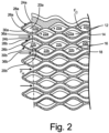
- FIGS. 1 and 2 will be discussed concurrently.
- FIG. 1 is a perspective view of a cross-section of heat exchanger 10.
- FIG. 2 is a side view of a cross-section of heat exchanger 10.
- FIGS. 1 and 2 include first layer 12, second layer 14, third layer 16, and fourth layer 18.
- First layer 12, second layer 14, third layer 16, and fourth layer 18 can be made from many different materials including copper, titanium, stainless steel, aluminum, graphite, ceramics, composites, plastics, and/or any other material with a relatively high thermal conductivity.
- First layer 12, second layer 14, third layer 16, and fourth layer 18 can all be made from the same material, or each layer can be made of a different material.
- first layer 12, second layer 14, third layer 16, and fourth layer 18 each has a triangular edge with a curvature ratio extending in direction X and first layer 12, second layer 14, third layer 16, and fourth layer 18 each has a triangular edge with a curvature ratio extending in direction Y.
- first layer 12, second layer 14, third layer 16, and fourth layer 18 each can have a sinusoidal wave shape, or any other repeating pattern extending in direction X and first layer 12, second layer 14, third layer 16, and fourth layer 18 each can have a sinusoidal wave shape, or any other repeating pattern extending in direction Y.
- First layer 12 includes overhang 20a and a plurality of passages 22a.
- Second layer 14 includes a plurality of passages 36a.
- Third layer 16 includes overhang 20b (overhang 20a and overhang 20b are hereinafter referred to as "overhangs 20") and a plurality of passages 22b (plurality of passages 22a and plurality of passages 22b are hereinafter referred to as "passages 22").
- First layer 12 and third layer 16 each extend further in direction X than second layer 14 and fourth layer 18 each extend in direction X, thereby creating overhangs 20.
- Fourth layer 18 includes a plurality of passages 36b (plurality of passages 36a and plurality of passages 36b are hereinafter referred to as "passages 36").
- Second layer 14 and fourth layer 18 can each extend further in direction Y than first layer 12 and third layer 16 to form overhangs (not shown) on second layer 14 and fourth layer 18.
- first layer 12 and third layer 16 each guide cold fluid F C through passages 22, while second layer 14 and fourth layer 18 each guide hot fluid F H through passages 36.
- first layer 12 and third layer 16 can each guide hot fluid F H through passages 22, while second layer 14 and fourth layer 18 can each guide cold fluid F C through passages 36.
- Each overhang 20 includes base end 24, distal end 26, first surface 28, and second surface 30.
- First surface 28 of overhang 20 and second surface 30 of overhang 20 extend from base end 24 of overhang 20 and come together to a bullnose point at distal end 26 of overhang 20.
- first surface 28 of overhang 20 and second surface 30 of overhang 20 can extend from base end 24 of overhang 20 and come together at distal end 26 of overhang 20 in many different shapes, such as a taper point, blunt taper point, taper cut, or any other convex point.
- First surface 28 of overhang 20 includes a plurality of troughs 32a.
- Second surface 30 of overhang 20 includes a plurality of troughs 32b (plurality of troughs 32a and plurality of troughs 32b hereinafter referred to as "troughs 32").
- Each of troughs 32 is aligned with one of passages 36 to direct hot fluid F H flow from distal end 26 of overhang 20 into passages 36, thus making the transition from distal end 26 of overhang 20 to passages 36 as smooth as possible.
- Troughs 32a on first surface 28 are offset from troughs 32b of second surface 30 in direction Y.
- troughs 32 increase in amplitude, or height, as troughs 36 extend toward base end of overhang 20.
- a smooth transition from distal end 26 of overhang 20 to passages 36 decreases the pressure drop across heat exchanger 10.
- a smooth transition from distal end 26 of overhang 20 to passages 36 reduces the impingement of hot air on concave surfaces that expose heat exchanger 10 to transient thermal stresses. Reducing the transient thermal stresses caused the impingement of hot air can reduce permanent deformation in heat exchanger 10 and increase the operating life of heat exchanger 10.
- hot fluid F H can flow through first layer 12 and third layer 16, while cool fluid F C can flow through second layer 14 and fourth layer 18.
- hot fluid F H will first contact distal end 26 of overhang 20. From distal end 26 troughs 32 can guide hot fluid F H toward base end 24 of overhang 20. Once hot fluid F H reaches base end 24, hot fluid F H enters passages 36.
- Overhang 20 is configured to make the transition from distal end 26 of overhang 20 to passages 36 as smooth as possible to minimize the pressure loss of heat exchanger 10.
- Heat exchanger 10 there are many different options to build first layer 12, second layer 14, third layer 16, and fourth layer 18.
- Heat exchanger 10 can be made through additive manufacturing, which enables heat exchanger 10 to be a unitary monolithic component. Additive manufacturing also enables heat exchanger 10 to be manufactured in a single process step, potentially reducing manufacturing time and cost. In another embodiment, heat exchanger 10 could be joined through brazing, welding, soldering, and/or any other joining method used in the forming of heat exchangers.
- a heat exchanger in one embodiment of the present disclosure, includes a first layer, a second layer, and a third layer.
- the first layer includes a first width W 1 extending in a first direction and a first length L 1 extending in a second direction.
- the second layer includes a second length L 2 extending in the first direction and a second width W 2 extending in the second direction.
- the third layer includes a third width W 3 extending in the first direction and a third length L 3 extending in a second direction.
- the second layer is between the first layer and the third layer.
- the first length L 1 of the first layer and the third length L 3 of the third layer both extend further in the second direction than the second width W 2 of the second layer.
- the first layer and the third layer each includes an overhang.
- the heat exchanger of the preceding paragraph can optionally include, additionally and/or alternatively, any one or more of the following features, configurations and/or additional components:
- a method for making a heat exchanger includes forming a first layer including a first width W 1 extending in a sinusoidal shape in a first direction and a first length L 1 extending in a sinusoidal shape in a second direction. Forming a second layer including a second length L 2 extending in a sinusoidal shape in the first direction and a second width W 2 extending in a sinusoidal shape in the second direction. Forming a third layer includes a third width W 3 extending in a sinusoidal shape in the first direction and a third length L 3 extending in a sinusoidal shape in the second direction. The second layer is between the first layer and the second layer.
- the first length L 1 of the first layer and the third length L 3 of the third layer both extend further in the second direction than the second width W 2 of the second layer.
- the first layer and the third layer each include an overhang.
- the second length L 2 of the second layer extends further in the first direction than the first width W 1 of the first layer and the third width W 3 of the third layer.
- the second layer includes an overhang.
- the method of making a heat exchanger of the preceding paragraph can optionally include, additionally and/or alternatively, any one or more of the following features, configurations and/or additional components:
Landscapes
- Engineering & Computer Science (AREA)
- Physics & Mathematics (AREA)
- Thermal Sciences (AREA)
- Mechanical Engineering (AREA)
- General Engineering & Computer Science (AREA)
- Chemical & Material Sciences (AREA)
- Manufacturing & Machinery (AREA)
- Materials Engineering (AREA)
- Heat-Exchange Devices With Radiators And Conduit Assemblies (AREA)
Claims (8)
- Échangeur de chaleur comprenant :
une première couche (12), dans lequel la première couche comprend :une première largeur W1 s'étendant dans une première direction ; etune première longueur L1 s'étendant dans une seconde direction ; une deuxième couche (14), dans lequel la deuxième couche comprend :une deuxième longueur L2 s'étendant dans la première direction ;une deuxième largeur W2 s'étendant dans la seconde direction ; etau moins un passage (22) s'étendant dans la seconde direction, depuis un bord de la deuxième couche, à travers un bord opposé de la deuxième couche ; etune troisième couche (16), dans lequel la troisième couche comprend une troisième largeur W3 s'étendant dans la première direction et une troisième longueur L3 s'étendant dans la seconde direction, la deuxième couche étant située entre la première couche et la troisième couche, la première longueur L1 de la première couche et la troisième longueur L3 de la troisième couche s'étendant toutes deux plus loin dans la seconde direction que la deuxième largeur W2 de la deuxième couche, et la première couche et la troisième couche comprenant chacune un surplomb (20) ;dans lequel le surplomb de la première couche et le surplomb de la troisième couche comprennent chacun :une extrémité de base (24) au même niveau qu'un bord de la deuxième couche ;une extrémité distale (26) opposée à l'extrémité de base, le surplomb se rétrécissant depuis l'extrémité de base jusqu'à l'extrémité distale ;une première surface (28) s'étendant de l'extrémité de base à l'extrémité distale ;une seconde surface (30) s'étendant de l'extrémité de base à l'extrémité distale, la première surface et la seconde surface se rencontrant au niveau de l'extrémité distale, et la première surface et la seconde surface étant chacune ondulées ; etau moins un creux (32) sur la première surface et au moins un creux sur la seconde surface, chacun parmi l'au moins un creux s'étendant de l'extrémité distale à l'extrémité de base, et l'un parmi l'au moins un creux étant aligné avec un passage de la deuxième couche ; dans lequel la deuxième longueur L2 de la deuxième couche s'étend plus loin dans la première direction que la première largeur Wl de la première couche et de la troisième largeur W3 de la troisième couche, et dans lequel la deuxième couche comprend un surplomb (20) ; et dans lequel le surplomb de la première couche comprend en outre une courbe sinusoïdale dans la première direction et une courbe sinusoïdale dans la seconde direction. - Échangeur de chaleur selon une quelconque revendication précédente, dans lequel le surplomb de la troisième couche comprend en outre une courbe sinusoïdale dans la première direction et une courbe sinusoïdale dans la seconde direction.
- Échangeur de chaleur selon la revendication 1 ou selon une quelconque revendication qui en dépend, dans lequel le surplomb de la deuxième couche comprend une courbe sinusoïdale dans la première direction et une courbe sinusoïdale dans la seconde direction.
- Échangeur de chaleur selon une quelconque revendication précédente, dans lequel la première couche, la deuxième couche et la troisième couche sont construites par fabrication additive de sorte que l'échangeur de chaleur est un composant continu et monolithique.
- Procédé de fabrication d'un échangeur de chaleur selon la revendication 1, le procédé comprenant :la formation d'une première couche comprenant une première largeur W1 s'étendant selon une forme sinusoïdale dans une première direction et une première longueur L1 s'étendant selon une forme sinusoïdale dans une seconde direction ;la formation d'une deuxième couche comprenant une deuxième longueur L2 s'étendant selon une forme sinusoïdale dans la première direction et une seconde largeur W2 s'étendant selon une forme sinusoïdale dans la seconde direction ; etla formation d'une troisième couche comprenant une troisième largeur W3 s'étendant selon une forme sinusoïdale dans la première direction et une troisième longueur L3 s'étendant selon une forme sinusoïdale dans la seconde direction, la deuxième couche étant située entre la première couche et la deuxième couche, et dans lequel la première longueur L1 de la première couche et la troisième longueur L3 de la troisième couche s'étendent toutes deux plus loin dans la seconde direction que la deuxième largeur W2 de la deuxième couche et la première couche et la troisième couche comprennent chacune un surplomb, et la deuxième longueur L2 de la deuxième couche s'étend plus loin dans la première direction que la première largeur W1 de la première couche et la troisième largeur W3 de la troisième couche, et dans lequel la deuxième couche comprend un surplomb, dans lequel le surplomb de la première couche et le surplomb de la troisième couche comprennent chacun :une extrémité de base (24) au même niveau qu'un bord de la deuxième couche ;une extrémité distale (26) opposée à l'extrémité de base, le surplomb se rétrécissant depuis l'extrémité de base jusqu'à l'extrémité distale ;une première surface (28) s'étendant de l'extrémité de base à l'extrémité distale ;une seconde surface (30) s'étendant de l'extrémité de base à l'extrémité distale, la première surface et la seconde surface se rencontrant au niveau de l'extrémité distale, et la première surface et la seconde surface étant chacune ondulées ; etau moins un creux (32) sur la première surface et au moins un creux sur la seconde surface, chacun parmi l'au moins un creux s'étendant de l'extrémité distale à l'extrémité de base, et l'un parmi l'au moins un creux étant aligné avec un passage de la deuxième couche.
- Procédé selon la revendication 5 comprenant en outre :
la formation d'une quatrième couche comprenant une quatrième longueur L4 s'étendant selon une forme sinusoïdale dans la première direction et une deuxième largeur W2 s'étendant selon une forme sinusoïdale dans la seconde direction. - Procédé selon la revendication 6 comprenant en outre :
la fabrication additive de la première couche, de la deuxième couche, de la troisième couche et de la quatrième couche. - Procédé selon la revendication 6 ou 7, dans lequel la première couche, la deuxième couche, la troisième couche et la quatrième couche sont continues et monolithiques.
Applications Claiming Priority (1)
| Application Number | Priority Date | Filing Date | Title |
|---|---|---|---|
| US16/655,461 US20210116183A1 (en) | 2019-10-17 | 2019-10-17 | Extended inlet surfaces for additive manufactured heat exchangers |
Publications (2)
| Publication Number | Publication Date |
|---|---|
| EP3809082A1 EP3809082A1 (fr) | 2021-04-21 |
| EP3809082B1 true EP3809082B1 (fr) | 2024-05-01 |
Family
ID=68766597
Family Applications (1)
| Application Number | Title | Priority Date | Filing Date |
|---|---|---|---|
| EP19213137.3A Active EP3809082B1 (fr) | 2019-10-17 | 2019-12-03 | Échangeur de chaleur |
Country Status (2)
| Country | Link |
|---|---|
| US (1) | US20210116183A1 (fr) |
| EP (1) | EP3809082B1 (fr) |
Family Cites Families (9)
| Publication number | Priority date | Publication date | Assignee | Title |
|---|---|---|---|---|
| US2959400A (en) * | 1957-11-27 | 1960-11-08 | Modine Mfg Co | Prime surface heat exchanger with dimpled sheets |
| JP3864916B2 (ja) * | 2002-08-29 | 2007-01-10 | 株式会社デンソー | 熱交換器 |
| NL2003983C2 (en) * | 2009-12-18 | 2011-06-21 | Mircea Dinulescu | Plate type heat exchanger and method of manufacturing heat exchanger plate. |
| US20180334952A1 (en) * | 2011-05-18 | 2018-11-22 | K&N Engineering, Inc. | Intercooler system |
| GB2565143B (en) * | 2017-08-04 | 2021-08-04 | Hieta Tech Limited | Heat exchanger |
| DE102017222740B3 (de) * | 2017-12-14 | 2019-03-14 | Hanon Systems | Abgaskühler und Abgasrückführsystem mit einem Abgaskühler |
| US11686530B2 (en) * | 2018-03-16 | 2023-06-27 | Hamilton Sundstrand Corporation | Plate fin heat exchanger flexible manifold |
| US11306979B2 (en) * | 2018-12-05 | 2022-04-19 | Hamilton Sundstrand Corporation | Heat exchanger riblet and turbulator features for improved manufacturability and performance |
| US20210254896A1 (en) * | 2020-02-19 | 2021-08-19 | Honeywell International Inc. | Heat exchanger with undulating plates |
-
2019
- 2019-10-17 US US16/655,461 patent/US20210116183A1/en not_active Abandoned
- 2019-12-03 EP EP19213137.3A patent/EP3809082B1/fr active Active
Also Published As
| Publication number | Publication date |
|---|---|
| EP3809082A1 (fr) | 2021-04-21 |
| US20210116183A1 (en) | 2021-04-22 |
Similar Documents
| Publication | Publication Date | Title |
|---|---|---|
| US11668533B2 (en) | Method for manufacturing a curved heat exchanger using wedge shaped segments | |
| US8770269B2 (en) | Three phase fin surface cooler | |
| EP3244153B1 (fr) | Échangeur de chaleur | |
| EP3499170B1 (fr) | Entrée d'embouchure d'échangeur de chaleur | |
| EP1840330B1 (fr) | Agencement de turbulateurs pour passages d' écoulement | |
| US6504274B2 (en) | Generator stator cooling design with concavity surfaces | |
| EP3258203B1 (fr) | Échangeur de chaleur à ailettes fines complexes | |
| EP3553446B1 (fr) | Bord d'attaque profilé d'échangeur de chaleur à ailettes et plaque coulée | |
| US10473403B2 (en) | Heat exchanger | |
| US5095973A (en) | Heat exchangers | |
| KR20210059794A (ko) | 열 교환기 | |
| US20190024520A1 (en) | Turbine blade cooling | |
| EP3176533B1 (fr) | Échangeur de chaleur en céramique à écoulement transversal et procédé de fabrication | |
| EP3047225B1 (fr) | Profil d'élément d'échange thermique ayant des caractéristiques de capacité de nettoyage améliorées | |
| CN104769379A (zh) | 用于换热器的交换元件、包括该交换元件的换热器和用于制造该交换元件的方法 | |
| EP0838650B1 (fr) | Echangeur de chaleur avec plaques d'ailettes bosselées | |
| EP3809082A1 (fr) | Surfaces d'entrée étendues pour échangeurs de chaleur fabriqués de manière additive | |
| EP3647703B1 (fr) | Fentes d'ailettes fabriquées de manière additive pour croissance thermique | |
| EP3553448B1 (fr) | Fonctionnalités du côté froid appliquées secondairement pour échangeur de chaleur moulé | |
| EP3043138B1 (fr) | Échangeur de chaleur à plaques avec ailettes ondulées | |
| CN112923775A (zh) | 热交换器和包括该热交换器的被冷却的电气组件 | |
| EP2954169B1 (fr) | Composant de turbine | |
| JP2009052874A (ja) | プレートフィン式熱交換器 | |
| EP4155651B1 (fr) | Tube plat pour échangeur de chaleur | |
| CN121844177A (zh) | 通过叠层实体制造法制造的换热器和冷板 |
Legal Events
| Date | Code | Title | Description |
|---|---|---|---|
| PUAI | Public reference made under article 153(3) epc to a published international application that has entered the european phase |
Free format text: ORIGINAL CODE: 0009012 |
|
| STAA | Information on the status of an ep patent application or granted ep patent |
Free format text: STATUS: THE APPLICATION HAS BEEN PUBLISHED |
|
| AK | Designated contracting states |
Kind code of ref document: A1 Designated state(s): AL AT BE BG CH CY CZ DE DK EE ES FI FR GB GR HR HU IE IS IT LI LT LU LV MC MK MT NL NO PL PT RO RS SE SI SK SM TR |
|
| AX | Request for extension of the european patent |
Extension state: BA ME |
|
| STAA | Information on the status of an ep patent application or granted ep patent |
Free format text: STATUS: REQUEST FOR EXAMINATION WAS MADE |
|
| 17P | Request for examination filed |
Effective date: 20211021 |
|
| RBV | Designated contracting states (corrected) |
Designated state(s): AL AT BE BG CH CY CZ DE DK EE ES FI FR GB GR HR HU IE IS IT LI LT LU LV MC MK MT NL NO PL PT RO RS SE SI SK SM TR |
|
| STAA | Information on the status of an ep patent application or granted ep patent |
Free format text: STATUS: EXAMINATION IS IN PROGRESS |
|
| 17Q | First examination report despatched |
Effective date: 20230629 |
|
| GRAP | Despatch of communication of intention to grant a patent |
Free format text: ORIGINAL CODE: EPIDOSNIGR1 |
|
| STAA | Information on the status of an ep patent application or granted ep patent |
Free format text: STATUS: GRANT OF PATENT IS INTENDED |
|
| INTG | Intention to grant announced |
Effective date: 20240129 |
|
| GRAS | Grant fee paid |
Free format text: ORIGINAL CODE: EPIDOSNIGR3 |
|
| GRAA | (expected) grant |
Free format text: ORIGINAL CODE: 0009210 |
|
| STAA | Information on the status of an ep patent application or granted ep patent |
Free format text: STATUS: THE PATENT HAS BEEN GRANTED |
|
| AK | Designated contracting states |
Kind code of ref document: B1 Designated state(s): AL AT BE BG CH CY CZ DE DK EE ES FI FR GB GR HR HU IE IS IT LI LT LU LV MC MK MT NL NO PL PT RO RS SE SI SK SM TR |
|
| REG | Reference to a national code |
Ref country code: GB Ref legal event code: FG4D |
|
| REG | Reference to a national code |
Ref country code: CH Ref legal event code: EP |
|
| REG | Reference to a national code |
Ref country code: IE Ref legal event code: FG4D |
|
| REG | Reference to a national code |
Ref country code: DE Ref legal event code: R096 Ref document number: 602019051280 Country of ref document: DE |
|
| REG | Reference to a national code |
Ref country code: LT Ref legal event code: MG9D |
|
| REG | Reference to a national code |
Ref country code: NL Ref legal event code: MP Effective date: 20240501 |
|
| PG25 | Lapsed in a contracting state [announced via postgrant information from national office to epo] |
Ref country code: IS Free format text: LAPSE BECAUSE OF FAILURE TO SUBMIT A TRANSLATION OF THE DESCRIPTION OR TO PAY THE FEE WITHIN THE PRESCRIBED TIME-LIMIT Effective date: 20240901 |
|
| PG25 | Lapsed in a contracting state [announced via postgrant information from national office to epo] |
Ref country code: BG Free format text: LAPSE BECAUSE OF FAILURE TO SUBMIT A TRANSLATION OF THE DESCRIPTION OR TO PAY THE FEE WITHIN THE PRESCRIBED TIME-LIMIT Effective date: 20240501 |
|
| PG25 | Lapsed in a contracting state [announced via postgrant information from national office to epo] |
Ref country code: HR Free format text: LAPSE BECAUSE OF FAILURE TO SUBMIT A TRANSLATION OF THE DESCRIPTION OR TO PAY THE FEE WITHIN THE PRESCRIBED TIME-LIMIT Effective date: 20240501 Ref country code: FI Free format text: LAPSE BECAUSE OF FAILURE TO SUBMIT A TRANSLATION OF THE DESCRIPTION OR TO PAY THE FEE WITHIN THE PRESCRIBED TIME-LIMIT Effective date: 20240501 |
|
| PG25 | Lapsed in a contracting state [announced via postgrant information from national office to epo] |
Ref country code: GR Free format text: LAPSE BECAUSE OF FAILURE TO SUBMIT A TRANSLATION OF THE DESCRIPTION OR TO PAY THE FEE WITHIN THE PRESCRIBED TIME-LIMIT Effective date: 20240802 |
|
| PG25 | Lapsed in a contracting state [announced via postgrant information from national office to epo] |
Ref country code: PT Free format text: LAPSE BECAUSE OF FAILURE TO SUBMIT A TRANSLATION OF THE DESCRIPTION OR TO PAY THE FEE WITHIN THE PRESCRIBED TIME-LIMIT Effective date: 20240902 |
|
| REG | Reference to a national code |
Ref country code: AT Ref legal event code: MK05 Ref document number: 1682866 Country of ref document: AT Kind code of ref document: T Effective date: 20240501 |
|
| PG25 | Lapsed in a contracting state [announced via postgrant information from national office to epo] |
Ref country code: NL Free format text: LAPSE BECAUSE OF FAILURE TO SUBMIT A TRANSLATION OF THE DESCRIPTION OR TO PAY THE FEE WITHIN THE PRESCRIBED TIME-LIMIT Effective date: 20240501 |
|
| PG25 | Lapsed in a contracting state [announced via postgrant information from national office to epo] |
Ref country code: ES Free format text: LAPSE BECAUSE OF FAILURE TO SUBMIT A TRANSLATION OF THE DESCRIPTION OR TO PAY THE FEE WITHIN THE PRESCRIBED TIME-LIMIT Effective date: 20240501 |
|
| PG25 | Lapsed in a contracting state [announced via postgrant information from national office to epo] |
Ref country code: AT Free format text: LAPSE BECAUSE OF FAILURE TO SUBMIT A TRANSLATION OF THE DESCRIPTION OR TO PAY THE FEE WITHIN THE PRESCRIBED TIME-LIMIT Effective date: 20240501 |
|
| PG25 | Lapsed in a contracting state [announced via postgrant information from national office to epo] |
Ref country code: PL Free format text: LAPSE BECAUSE OF FAILURE TO SUBMIT A TRANSLATION OF THE DESCRIPTION OR TO PAY THE FEE WITHIN THE PRESCRIBED TIME-LIMIT Effective date: 20240501 |
|
| PG25 | Lapsed in a contracting state [announced via postgrant information from national office to epo] |
Ref country code: LV Free format text: LAPSE BECAUSE OF FAILURE TO SUBMIT A TRANSLATION OF THE DESCRIPTION OR TO PAY THE FEE WITHIN THE PRESCRIBED TIME-LIMIT Effective date: 20240501 |
|
| PG25 | Lapsed in a contracting state [announced via postgrant information from national office to epo] |
Ref country code: PT Free format text: LAPSE BECAUSE OF FAILURE TO SUBMIT A TRANSLATION OF THE DESCRIPTION OR TO PAY THE FEE WITHIN THE PRESCRIBED TIME-LIMIT Effective date: 20240902 Ref country code: PL Free format text: LAPSE BECAUSE OF FAILURE TO SUBMIT A TRANSLATION OF THE DESCRIPTION OR TO PAY THE FEE WITHIN THE PRESCRIBED TIME-LIMIT Effective date: 20240501 Ref country code: NO Free format text: LAPSE BECAUSE OF FAILURE TO SUBMIT A TRANSLATION OF THE DESCRIPTION OR TO PAY THE FEE WITHIN THE PRESCRIBED TIME-LIMIT Effective date: 20240801 Ref country code: NL Free format text: LAPSE BECAUSE OF FAILURE TO SUBMIT A TRANSLATION OF THE DESCRIPTION OR TO PAY THE FEE WITHIN THE PRESCRIBED TIME-LIMIT Effective date: 20240501 Ref country code: LV Free format text: LAPSE BECAUSE OF FAILURE TO SUBMIT A TRANSLATION OF THE DESCRIPTION OR TO PAY THE FEE WITHIN THE PRESCRIBED TIME-LIMIT Effective date: 20240501 Ref country code: IS Free format text: LAPSE BECAUSE OF FAILURE TO SUBMIT A TRANSLATION OF THE DESCRIPTION OR TO PAY THE FEE WITHIN THE PRESCRIBED TIME-LIMIT Effective date: 20240901 Ref country code: HR Free format text: LAPSE BECAUSE OF FAILURE TO SUBMIT A TRANSLATION OF THE DESCRIPTION OR TO PAY THE FEE WITHIN THE PRESCRIBED TIME-LIMIT Effective date: 20240501 Ref country code: GR Free format text: LAPSE BECAUSE OF FAILURE TO SUBMIT A TRANSLATION OF THE DESCRIPTION OR TO PAY THE FEE WITHIN THE PRESCRIBED TIME-LIMIT Effective date: 20240802 Ref country code: FI Free format text: LAPSE BECAUSE OF FAILURE TO SUBMIT A TRANSLATION OF THE DESCRIPTION OR TO PAY THE FEE WITHIN THE PRESCRIBED TIME-LIMIT Effective date: 20240501 Ref country code: ES Free format text: LAPSE BECAUSE OF FAILURE TO SUBMIT A TRANSLATION OF THE DESCRIPTION OR TO PAY THE FEE WITHIN THE PRESCRIBED TIME-LIMIT Effective date: 20240501 Ref country code: BG Free format text: LAPSE BECAUSE OF FAILURE TO SUBMIT A TRANSLATION OF THE DESCRIPTION OR TO PAY THE FEE WITHIN THE PRESCRIBED TIME-LIMIT Effective date: 20240501 Ref country code: AT Free format text: LAPSE BECAUSE OF FAILURE TO SUBMIT A TRANSLATION OF THE DESCRIPTION OR TO PAY THE FEE WITHIN THE PRESCRIBED TIME-LIMIT Effective date: 20240501 Ref country code: RS Free format text: LAPSE BECAUSE OF FAILURE TO SUBMIT A TRANSLATION OF THE DESCRIPTION OR TO PAY THE FEE WITHIN THE PRESCRIBED TIME-LIMIT Effective date: 20240801 |
|
| PG25 | Lapsed in a contracting state [announced via postgrant information from national office to epo] |
Ref country code: DK Free format text: LAPSE BECAUSE OF FAILURE TO SUBMIT A TRANSLATION OF THE DESCRIPTION OR TO PAY THE FEE WITHIN THE PRESCRIBED TIME-LIMIT Effective date: 20240501 |
|
| PG25 | Lapsed in a contracting state [announced via postgrant information from national office to epo] |
Ref country code: EE Free format text: LAPSE BECAUSE OF FAILURE TO SUBMIT A TRANSLATION OF THE DESCRIPTION OR TO PAY THE FEE WITHIN THE PRESCRIBED TIME-LIMIT Effective date: 20240501 |
|
| PG25 | Lapsed in a contracting state [announced via postgrant information from national office to epo] |
Ref country code: CZ Free format text: LAPSE BECAUSE OF FAILURE TO SUBMIT A TRANSLATION OF THE DESCRIPTION OR TO PAY THE FEE WITHIN THE PRESCRIBED TIME-LIMIT Effective date: 20240501 |
|
| PG25 | Lapsed in a contracting state [announced via postgrant information from national office to epo] |
Ref country code: SK Free format text: LAPSE BECAUSE OF FAILURE TO SUBMIT A TRANSLATION OF THE DESCRIPTION OR TO PAY THE FEE WITHIN THE PRESCRIBED TIME-LIMIT Effective date: 20240501 Ref country code: RO Free format text: LAPSE BECAUSE OF FAILURE TO SUBMIT A TRANSLATION OF THE DESCRIPTION OR TO PAY THE FEE WITHIN THE PRESCRIBED TIME-LIMIT Effective date: 20240501 |
|
| PG25 | Lapsed in a contracting state [announced via postgrant information from national office to epo] |
Ref country code: SM Free format text: LAPSE BECAUSE OF FAILURE TO SUBMIT A TRANSLATION OF THE DESCRIPTION OR TO PAY THE FEE WITHIN THE PRESCRIBED TIME-LIMIT Effective date: 20240501 |
|
| PG25 | Lapsed in a contracting state [announced via postgrant information from national office to epo] |
Ref country code: SM Free format text: LAPSE BECAUSE OF FAILURE TO SUBMIT A TRANSLATION OF THE DESCRIPTION OR TO PAY THE FEE WITHIN THE PRESCRIBED TIME-LIMIT Effective date: 20240501 Ref country code: SK Free format text: LAPSE BECAUSE OF FAILURE TO SUBMIT A TRANSLATION OF THE DESCRIPTION OR TO PAY THE FEE WITHIN THE PRESCRIBED TIME-LIMIT Effective date: 20240501 Ref country code: RO Free format text: LAPSE BECAUSE OF FAILURE TO SUBMIT A TRANSLATION OF THE DESCRIPTION OR TO PAY THE FEE WITHIN THE PRESCRIBED TIME-LIMIT Effective date: 20240501 Ref country code: EE Free format text: LAPSE BECAUSE OF FAILURE TO SUBMIT A TRANSLATION OF THE DESCRIPTION OR TO PAY THE FEE WITHIN THE PRESCRIBED TIME-LIMIT Effective date: 20240501 Ref country code: DK Free format text: LAPSE BECAUSE OF FAILURE TO SUBMIT A TRANSLATION OF THE DESCRIPTION OR TO PAY THE FEE WITHIN THE PRESCRIBED TIME-LIMIT Effective date: 20240501 Ref country code: CZ Free format text: LAPSE BECAUSE OF FAILURE TO SUBMIT A TRANSLATION OF THE DESCRIPTION OR TO PAY THE FEE WITHIN THE PRESCRIBED TIME-LIMIT Effective date: 20240501 |
|
| REG | Reference to a national code |
Ref country code: DE Ref legal event code: R097 Ref document number: 602019051280 Country of ref document: DE |
|
| PG25 | Lapsed in a contracting state [announced via postgrant information from national office to epo] |
Ref country code: IT Free format text: LAPSE BECAUSE OF FAILURE TO SUBMIT A TRANSLATION OF THE DESCRIPTION OR TO PAY THE FEE WITHIN THE PRESCRIBED TIME-LIMIT Effective date: 20240501 |
|
| PLBE | No opposition filed within time limit |
Free format text: ORIGINAL CODE: 0009261 |
|
| STAA | Information on the status of an ep patent application or granted ep patent |
Free format text: STATUS: NO OPPOSITION FILED WITHIN TIME LIMIT |
|
| 26N | No opposition filed |
Effective date: 20250204 |
|
| PG25 | Lapsed in a contracting state [announced via postgrant information from national office to epo] |
Ref country code: SI Free format text: LAPSE BECAUSE OF FAILURE TO SUBMIT A TRANSLATION OF THE DESCRIPTION OR TO PAY THE FEE WITHIN THE PRESCRIBED TIME-LIMIT Effective date: 20240501 |
|
| PG25 | Lapsed in a contracting state [announced via postgrant information from national office to epo] |
Ref country code: MC Free format text: LAPSE BECAUSE OF FAILURE TO SUBMIT A TRANSLATION OF THE DESCRIPTION OR TO PAY THE FEE WITHIN THE PRESCRIBED TIME-LIMIT Effective date: 20240501 |
|
| REG | Reference to a national code |
Ref country code: CH Ref legal event code: PL |
|
| PG25 | Lapsed in a contracting state [announced via postgrant information from national office to epo] |
Ref country code: LU Free format text: LAPSE BECAUSE OF NON-PAYMENT OF DUE FEES Effective date: 20241203 |
|
| PG25 | Lapsed in a contracting state [announced via postgrant information from national office to epo] |
Ref country code: SE Free format text: LAPSE BECAUSE OF FAILURE TO SUBMIT A TRANSLATION OF THE DESCRIPTION OR TO PAY THE FEE WITHIN THE PRESCRIBED TIME-LIMIT Effective date: 20240501 |
|
| REG | Reference to a national code |
Ref country code: BE Ref legal event code: MM Effective date: 20241231 |
|
| PG25 | Lapsed in a contracting state [announced via postgrant information from national office to epo] |
Ref country code: BE Free format text: LAPSE BECAUSE OF NON-PAYMENT OF DUE FEES Effective date: 20241231 |
|
| PG25 | Lapsed in a contracting state [announced via postgrant information from national office to epo] |
Ref country code: CH Free format text: LAPSE BECAUSE OF NON-PAYMENT OF DUE FEES Effective date: 20241231 |
|
| PG25 | Lapsed in a contracting state [announced via postgrant information from national office to epo] |
Ref country code: IE Free format text: LAPSE BECAUSE OF NON-PAYMENT OF DUE FEES Effective date: 20241203 |
|
| PGFP | Annual fee paid to national office [announced via postgrant information from national office to epo] |
Ref country code: DE Payment date: 20251126 Year of fee payment: 7 |
|
| PGFP | Annual fee paid to national office [announced via postgrant information from national office to epo] |
Ref country code: GB Payment date: 20251120 Year of fee payment: 7 |
|
| PGFP | Annual fee paid to national office [announced via postgrant information from national office to epo] |
Ref country code: FR Payment date: 20251120 Year of fee payment: 7 |
|
| PG25 | Lapsed in a contracting state [announced via postgrant information from national office to epo] |
Ref country code: CY Free format text: LAPSE BECAUSE OF FAILURE TO SUBMIT A TRANSLATION OF THE DESCRIPTION OR TO PAY THE FEE WITHIN THE PRESCRIBED TIME-LIMIT; INVALID AB INITIO Effective date: 20191203 |