EP3809147B1 - Dispositif de test in-situ utilisé dans un système ultravide - Google Patents
Dispositif de test in-situ utilisé dans un système ultravide Download PDFInfo
- Publication number
- EP3809147B1 EP3809147B1 EP18922778.8A EP18922778A EP3809147B1 EP 3809147 B1 EP3809147 B1 EP 3809147B1 EP 18922778 A EP18922778 A EP 18922778A EP 3809147 B1 EP3809147 B1 EP 3809147B1
- Authority
- EP
- European Patent Office
- Prior art keywords
- testing chamber
- rod
- tube
- measuring head
- disposed
- Prior art date
- Legal status (The legal status is an assumption and is not a legal conclusion. Google has not performed a legal analysis and makes no representation as to the accuracy of the status listed.)
- Active
Links
Images




Classifications
-
- G—PHYSICS
- G01—MEASURING; TESTING
- G01R—MEASURING ELECTRIC VARIABLES; MEASURING MAGNETIC VARIABLES
- G01R31/00—Arrangements for testing electric properties; Arrangements for locating electric faults; Arrangements for electrical testing characterised by what is being tested not provided for elsewhere
-
- G—PHYSICS
- G01—MEASURING; TESTING
- G01R—MEASURING ELECTRIC VARIABLES; MEASURING MAGNETIC VARIABLES
- G01R1/00—Details of instruments or arrangements of the types included in groups G01R5/00 - G01R13/00 and G01R31/00
- G01R1/02—General constructional details
- G01R1/04—Housings; Supporting members; Arrangements of terminals
-
- G—PHYSICS
- G01—MEASURING; TESTING
- G01R—MEASURING ELECTRIC VARIABLES; MEASURING MAGNETIC VARIABLES
- G01R1/00—Details of instruments or arrangements of the types included in groups G01R5/00 - G01R13/00 and G01R31/00
- G01R1/02—General constructional details
- G01R1/06—Measuring leads; Measuring probes
- G01R1/067—Measuring probes
-
- G—PHYSICS
- G01—MEASURING; TESTING
- G01R—MEASURING ELECTRIC VARIABLES; MEASURING MAGNETIC VARIABLES
- G01R1/00—Details of instruments or arrangements of the types included in groups G01R5/00 - G01R13/00 and G01R31/00
- G01R1/02—General constructional details
- G01R1/06—Measuring leads; Measuring probes
- G01R1/067—Measuring probes
- G01R1/06794—Devices for sensing when probes are in contact, or in position to contact, with measured object
Definitions
- the present invention relates to the technical field of ultra-high vacuum experiment, in particular to an in-situ testing device.
- Samples can be well protected in an ultra-high vacuum.
- different measurement environments such as different temperature ranges, different magnetic field intensities, etc.
- different means such as different temperature ranges, different magnetic field intensities, etc.
- a tester must ensure that the sample is aligned with a probe.
- a new probe cannot be aligned with the specified position of the sample again due to limitions of observation conditions and other factors. Therefore, when the sample is moved to a different test environment, it is necessary for the tester to align the probe with an electrode on the sample by an optical observation method before data are collected.
- the optical observation method cannot be performed in some test environments.
- the optical observation method cannot be implemented in a Dewar. Therefore, it is necessary for the tester to take the sample out from the ultra-high vacuum environment, align the probe with the electrode on the sample at a position where the optical observation can be performed, and after a preliminary test, combine the probe and the sample to form a measuring probe, and sent the measuring probe to a designated position in the Dewar. Therefore, the operation is relatively cumbersome, and the test efficiency is low.
- Document CN 104749470A discloses a transport property measuring system and comprises a measuring head and a measuring cavity.
- the drive mechanism includes a first power unit and a first transmission structure; the first power unit is connected to the first transmission structure; and the first transmission structure is connected to the shielding door and drives the shielding door.
- the opening extends from an end of the testing chamber to a side wall of the testing chamber; the shielding door is L-shaped; and one edge of the shielding door is rotatably connected to the side wall of the testing chamber.
- the first transmission structure includes a first driving gear and a first driven gear;
- the shielding door is provided with a door shaft;
- the door shaft is rotatably connected to the testing chamber; and
- the first driven gear is sleeved over the door shaft;
- the first power unit is a first magnetic force rotation hand;
- the first magnetic force rotation hand is connected to the first driving gear by a first long rod; and
- the first driving gear meshes with the first driven gear.
- the first long rod is connected to the first driving gear by a first universal joint.
- the in-situ testing device further includes an installing base; the testing chamber is arranged on the installing base, a bottom of the testing chamber has a through hole;
- the locking structure includes a second power unit, a second transmission structure and a threaded rod; the threaded rod is arranged on the installing base and extends into the testing chamber through the through hole; the interference structure includes a threaded hole disposed on a bottom of the measuring head and fitting the threaded rod; the second power unit is connected to the threaded rod by the second transmission structure, and configured to drive the threaded rod to screw into the threaded hole, thereby fixing the measuring head inside the testing chamber.
- the second transmission structure includes a second driving gear and a second driven gear; the second driven gear is rotatably arranged in the installing base; the second driven gear is connected to the threaded rod; the second power unit is a second magnetic force rotation hand; the second magnetic force rotation hand is connected to the second driving gear by a second long rod; and the second driving gear meshes with the second driven gear.
- the second long rod is connected to the second driving gear by a second universal joint.
- the threaded rod includes a first part, a second part, and an elastic member; the first part is rod-shaped and includes a threaded portion at an upper end and a cylindrical portion at a lower end; position restricting surfaces are disposed on oppisite side walls of the cylindrical portion;
- the in-situ testing device further includes a cold rod including an inner tube and an outer tube arranged concentrically;
- the in-situ testing device further includes a connecting board connected to the testing chamber, and the connecting board and the cooling component are provided with a plurality of third threaded holes corresponding to each other.
- the in-situ testing device further includes a second electrode adapter plate connected to one side of the connecting board, and a third electrode adapter plate is disposed on a side wall of the testing chamber and corresponds to the second electrode adapter plate .
- the in-situ testing device further includes a U-shaped wire combing rod arranged at a side of the third electrode adapter plate away from the second electrode adapter plate, and the U-shaped wire combing rod is configured to comb wires.
- the in-situ testing device further includes a first supporting member sleeved over the outer tube, and the first supporting member is configured to support the cold rod.
- the in-situ testing device further includes a connecting flange and a hollow linear propelling component, which are sleeved over the outer tube;
- the in-situ testing device further includes a first adapter flange connected to the second end of the hollow linear propelling component away from the connecting flange; the cold rod is installed on the first adapter flange; and the hollow linear propelling component is connected to the cold rod through the first adapter flange.
- the in-situ testing device further includes a wiring tube sleeved over the outer tube, where one end of the wiring tube is connected to the first adapter flange, and another end of the wiring tube is welded to the outer tube;
- the hollow linear propelling component includes an extendable-contractile tube, a support, a power structure, a third driving gear, a third driven gear, a threaded shaft, and a nut;
- the support is provided with a slide rail;
- a slide plate is slidaly disposed on the slide rail;
- the nut is arranged on the slide plate;
- the third driven gear is rotatably disposed on the support and connected to one end of the threaded shaft; another end of the threaded shaft is rotatably disposed in the nut;
- the beneficial effects of the present invention include:
- the testing chamber of the in-situ testing device of the present invention is installed in an ultra-high vacuum test system. Before the sample is moved to a different test environment, the sample and the probe are placed in the measuring head, and the shielding door is opened by the drive mechanism.
- the measuring head is placed into the testing chamber, so that the second optical observation hole of the measuring head is aligned with the first optical observation hole of the testing chamber.
- the sample is aligned with the probe by means of optical observation, and the preliminary test is performed to ensure that electrical properties are proper after the alignment; and then the measuring head is transported by the transportation device of the sample transport line to a designated position in a next testing environment.
- the in-situ testing device of the present invention provides the tester with a test platform for aligning the sample with the probe by means of optical observation and testing various electrical properties of the sample, which makes an automatic operation of the preliminary test of the sample possible.
- a test platform for aligning the sample with the probe by means of optical observation and testing various electrical properties of the sample, which makes an automatic operation of the preliminary test of the sample possible.
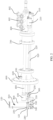
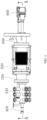
- the in-situ testing device 10 includes a measuring head 800, a drive mechanism 200, and a testing chamber 100.
- the testing chamber 100 is arranged on a sample transport line of the ultra-high vacuum system.
- the testing chamber 100 is provided with a first optical observation hole 110, and the measuring head 800 is provided with a second optical observation hole 810 whose position matches a position of the first optical observation hole 110.
- the testing chamber 100 is provided with an opening allowing the measuring head 800 to pass through.
- the testing chamber 100 is further provided with a shielding door 120, and the drive mechanism 200 is connected to the shielding door 120 and configured to drive the shielding door 120 to move relative to the testing chamber 100, to open or cover the opening, thereby opening or closing the testing chamber 100.
- a shape of the testing chamber 100 can be various.
- the testing chamber 100 is in a shape of a circular cylinder, a rectangle, a cube, or a cylinder with a semicircular cross section, etc. It can be understood that the testing chamber 100 can be a cylindrical structure with a semicircular cross section, which makes it convenient to arrange the shielding door 120 on the testing chamber 100.
- a position and a shape of the shielding door 120 can be various.
- the shielding door 120 can be disposed on a side wall or on a top of the testing chamber 100, only if the shielding door can allow the measuring head 800 to pass.
- the shielding door 120 is L-shaped, that is, an opening is disposed both on the top and in the side wall of the testing chamber 100.
- the shielding door 120 is configured to open or cover the opening, thereby opening or closing the testing chamber 100, and enabling the measuring head 800 to enter and exit the testing chamber 100 from multiple angles.
- the connection mode between the shielding door 120 and the testing chamber 100 can be various.
- the shielding door 120 can be rotatably or slidably connected to the testing chamber 100.
- the shielding door 120 can be provided with a door shaft, and the side wall of the testing chamber 100 can be provided with a bearing for fitting the door shaft.
- the structure of the drive mechanism 200 can be various.
- the drive mechanism 200 includes an electric extendable-contractile tube, an air cylinder or a hydraulic cylinder, etc.
- the the drive mechanism 200 can be disposed between the shielding door 120 and the testing chamber 100, thereby realizing a movement of the shielding door 120 relative to the testing chamber 100.
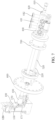
- the drive mechanism 200 includes a first power unit 210 and a first transmission structure; the first power unit 210 is connected to the first transmission structure; and the first transmission structure is connected to the shielding door 120 and drives the shielding door 120.
- the power output by the first power unit 210 is transmitted to the shielding door 120 by the first transmission structure, so that the shielding door 120 moves or rotates relative to the testing chamber 100.
- the first power unit 210 can be disposed outside the ultra-high vacuum test system, to facilitate the operation of the tester.
- a type of the first power unit 210 can be various.
- the first power unit 210 can be a motor, a magnetic force rotation hand, and so on.
- the structure of the first transmission structure can also be various.
- the first transmission structure includes a first driving gear 230 and a first driven gear 240.
- the shielding door 120 is provided with a door shaft 121, and the door shaft 121 is rotatably connected to the testing chamber 100.
- the first driven gear 240 is sleeved over the door shaft 121.
- the first power unit 210 is a first magnetic force rotation hand, and the first magnetic force rotation hand is connected to the first driving gear 230 through a first long rod 220.
- the first driving gear 230 meshes with the first driven gear 240.
- the first magnetic force rotation hand drives the first long rod 220 to rotate, and the first long rod 220 drives the first driving gear 230 to rotate, thereby driving the first driven gear 240 meshing with the first driving gear 230 to rotate, and futher driving the door shaft 121 to rotate.
- the first transmission structure drives the shielding door 120 to open or close relative to the testing chamber 100, which makes it convenient for the measuring head 800 to enter and exit the testing chamber 100.
- the first long rod 220 can be connected to the first driving gear 230 through a first universal joint 250.
- the first universal joint 250 connects the first long rod 220 to the first driving gear 230, thus a deviation caused by transmission is absorbed.
- the first transmission structure can include a transmission rod and two connecting rods; first ends of the two connecting rods are rotatably connected to each other, a second end of one connecting rod is rotatably connected to the shielding door 120, and a seond end of another connecting rod is rotatably connected to the testing chamber 100.
- the shielding door 120 is provided with the door shaft, and the door shaft is rotatably connected to the testing chamber 100.
- One end of the transmission rod is rotatably connected to the rotatably connected first ends of the two connecting rods, and another end of the transmission rod is connected to the first power unit 210.
- the first power unit 210 can be an electric extendable-contractile rod, a hydraulic cylinder, or an air cylinder, etc.
- the first power unit 210 drives the transmission rod to move, thereby driving the two connecting rods to move, and further driving the shielding door 120 to rotate relative to the testing chamber 100, so that the shielding door 120 opens or closes relative to the testing chamber 100.
- the sample is aligned with the probe by means of optical observation, and the preliminary test is performed, to ensure that electrical properties are proper after the alignment; and then the measuring head 800 is transported by the transportation device of the sample transport line to a designated position in a next testing environment.
- the in-situ testing device 10 of the embodiments provides the tester with a test platform for aligning the sample with the probe by means of optical observation and testing various electrical properties of the sample, which makes an automatic operation of the preliminary test of the sample possible.
- the in-situ testing device 10 further includes an installing base 900; the testing chamber 100 is arranged on the installing base 900; and a bottom of the testing chamber 100 has a through hole.
- a locking structure 300 is disposed on the installing base 900 and below the through hole of the testing chamber 100.
- An interference structure (not shown in the figures) that fits the locking structure 300 is arranged on the measuring head 800. The locking structure 300 fits the interference structure to fix the measuring head 800 inside the testing chamber 100.
- the structure of the locking structure 300 and the structure of the interference structure can be various.
- the locking structure 300 includes a second power unit 310, a second transmission structure, and a threaded rod 350.
- the threaded rod 350 is arranged on the installing base 900 and can extend into the testing chamber 100 through the through hole.
- the interference structure includes a threaded hole disposed on the bottom of the measuring head 800 and fitting the threaded rod 350.
- the second power unit 310 is connected to the threaded rod 350 by the second transmission structure, and configured to drive the threaded rod 350 to screw into the threaded hole, so that the measuring head 800 is fixed inside the testing chamber 100.
- the structure of the second power unit 310 can be various.
- the second power unit 310 can be an electric motor, an air cylinder, or a hydraulic cylinder, etc.
- the second power unit 310 is a second magnetic force rotation hand.
- the second transmission structure includes a second driving gear 330 and a second driven gear 340.
- the second driven gear 340 is rotatably arranged in the installing base 900, and the second driven gear 340 is connected to the threaded rod 350.
- the second magnetic force rotation hand is connected to the second driving gear 330 by a second long rod 320, and the second driving gear 330 meshes with the second driven gear 340.
- the second transmission structure can also have another structure, only if it can drive the threaded rod 350 to screw into or out from the threaded hole.
- the threaded rod 350 includes a first part 351, a second part 353, and an elastic member 354.
- the first part 351 is rod-shaped and includes a threaded portion at an upper end and a cylindrical portion at a lower end. Position restricting surfaces 352 are disposed on oppisite side walls of the cylindrical portion.
- the second part 353 is connected to the second driven gear 340; the second part 353 has a receiving hole for receiving the cylindrical portion; and the elastic member 354 is disposed inside the receiving hole and abusts against the cylindrical portion.
- An insertion hole is disposed in a side wall of the receiving hole and penetrates the side wall thereof.
- a restricting member is configured to be inserted into the insertion hole and abuts against the position restricting surfaces 352, thus preventing the first part 351 from rotating relative to the second part 353.
- the threaded rod 350 including the first part 351, the second part 353, and the elastic member 354, it is possible to reduce damage to the screws of the threaded rod 350 and the threaded hole by alleviating the effects of external forces.
- the restricting member and the position restricting surfaces 352 By arranging the restricting member and the position restricting surfaces 352, the first part 351 and the second part 353 can be prevented from rotating relatively, which facilitates the connection between the threaded rod 350 and the threaded hole.
- the restricting member can be a bolt, a pin, or the like.
- a bearing hole for receiving a bearing is disposed at an end of the second part 353, and the end of the second part 353 is away from the first part 351.
- the second part 353 is rotatably connected to the installing base 900 through a rotating bearing, so that, the second driven gear 340 can rotate more smoothly.
- the second long rod 320 can be connected to the second driving gear 330 by a second universal joint 360.
- the second universal joint 360 connects the second long rod 320 to the second driving gear 330, thus a deviation caused by the transmission can be absorbed.
- the locking structure 300 can further include two electric extendable-contractile tubes, and the two electric extendable-contractile tubes are relatively disposed inside the testing chamber 100.
- One end of each electric extendable-contractile tube is connected to an inner side wall of the testing chamber 100, and another end of each electric extendable-contractile tube is provided with an arc-shaped pad for clamping the measuring head 800.
- the lower end of the measuring head 800 can be provided with an annular groove for clamping each arc-shaped pad.
- the two electric extendable-contractile tubes move towards the measuring head 800, so that each arc-shaped pad is clamped in the annular groove disposed at the lower end of the measuring head 800, and that the measuring head 800 can be fixed in the testing chamber 100 by the two arc-shaped pads.
- the in-situ testing device 10 further includes a first electrode adapter plate 820 arranged at the lower end of the measuring head 800.
- the testing chamber 100 is provided with an electrode base 140 oppositely joined to the first electrode adapter plate 820.
- a plurality of grooves are asymmetrically disposed on the electrode base 140, and a plurality of protrusions 821 respectively fitting the plurality of grooves are disposed at the lower end of the measuring head 800.
- the plurality of grooves fit the plurality of protrusions 821, so that the first electrode adapter plate 820 is aligned with the electrode base 140 to form an electrical connection.
- the in-situ testing device 10 further includes a cold rod 400 and a cooling component 430.
- the cold rod 400 includes an inner tube 410 and an outer tube 420 which are arranged concentrically, and the cooling component 430 is arranged at one end of the cold rod 400.
- the inner tube 410 and the outer tube 420 communicate by means of the cooling component 430.
- the cooling component 430 is connected to the testing chamber 100.
- Another end of the cold rod 400 which is away from the cooling component 430, communicates with an external cooling device.
- the refrigerant flows into the inner tube 410 and flows out from the outer tube 420, so as to reduce a temperature of the measuring head 800.
- the temperature of the measuring head 800 is reduced by the cold rod 400, so that the tester can adjust the temperature inside the testing chamber 100 according to the requirements of the experiment.
- connection manner between the cold rod 400 and the testing chamber 100 can be various.
- the in-situ testing device 10 further includes a connecting board 170 connected to the testing chamber 100.
- the connecting board 170 and the cooling component 430 are provided with a plurality of third threaded holes corresponding to each other.
- the connecting board 170 can also be provided with a fourth threaded hole for connecting the connecting board 170 to the testing chamber 100.
- a connecting member (such as a screw, etc.) sequentially passes through one of the third threaded holes in the connecting board 170 and one of the third threaded holes in the cooling component 430 to realize the connection between the connecting board 170 and the cold rod 400.
- the connecting member passes through the fourth threaded hole in the connecting board 170 to realize the connection between the connecting board 170 and the testing chamber 100. So that, the connection between the cold rod 400 and the testing chamber 100 is achieved.
- the in-situ testing device 10 further includes a second electrode adapter plate 171 connected to one side of the connecting board 170.
- a third electrode adapter plate 150 corresponding to the second electrode adapter plate 171 is provided on a side wall of the testing chamber 100.
- the connecting board 170 not only facilitates the connection between the cold rod 400 and the testing chamber 100, but also makes it easier to achieve a wire connection between the testing chamber 100 and an external device or between the testing chamber 100 and other components of the whole device by means of the second electrode adapter plate 171 and the third electrode adapter plate 150.
- a heat sink can be provided on the second electrode adapter plate 171, and the heat sink can organize and cool the wires.
- the wires running from a room temperature environment are spirally wound on the cold rod 400 and then connected to the cooling component 430 of the cold rod 400, and at this time, the temperature of the wires has not yet fallen to a required temperature.
- Part of the wires are bonded on the heat sink, and the heat sink is tightly attached to the cold rod 400, thus better cooling the wires at this position, and ensuring that not too much heat is introduced into the testing chamber 100.
- the electrodes when the electrodes are disposed on the second electrode adapter plate 171 and the third electrode adapter plate 150, the electrodes can be sleeved with insulating pads, which not only improves stability of the electrodes, but also avoids leakage of electricity.
- a U-shaped wire combing rod 160 for combing the wires is arranged at a side of the third electrode adapter plate 150, and the side of the third electrode adapter plate 150 is away from the second electrode adapter plate 171. Two ends of the U-shaped wire combing rod 160 can be connected to the third electrode adapter plate 150.
- the in-situ testing device 10 further includes a first supporting member 450 sleeved over the outer tube 420, and the first supporting member 450 is configured to support the cold rod 400.
- the first supporting member 450 can also support the first long rod 220 and the second long rod 320.
- the first supporting member 450 makes the positions of the first long rod 220, the second long rod 320, and the cold rod 400 relatively fixed, thus the cold rod 400, the first long rod 220, and the second long rod 320 move more stably and do not interfere with each other.
- the first supporting member 450 can be provided with a bearing for cooperating with the first long rod 220 and the second long rod 320.
- the in-situ testing device 10 further includes a connecting flange 600 and a hollow linear propelling component 500, which are sleeved over the outer tube 420.
- a first end of the connecting flange 600 is provided with a second supporting member 610, and the second supporting member 610 is provided with a first rod hole allowing the cold rod 400 to pass.
- the first end of the connecting flange 600 is configured to connect an external fixed component.
- a first end of the hollow linear propelling component 500 is connected to a second end of the connecting flange 600, and the second end of the connecting flange 600 is away from the second supporting member 610.
- a second end of the hollow linear propelling component 500 is connected to the cold rod 400.
- the hollow linear propelling component 500 is configured to drive the cold rod 400 to move, so as to drive the testing chamber 100 to move.
- the second supporting member 610 also has holes allowing the first long rod 220 and the second long rod 320 to pass.
- the hollow linear propelling component 500 not only drives the cold rod 400 to move, but also drives the first long rod 220 and the second long rod 320 to move.
- the hollow linear propelling component 500 is configured to drive the testing chamber 100 to move in the ultra-high vacuum test system, so that the measuring head 800 in the testing chamber 100 can move to a position above next test device, thereby making it easy for the transportation device of the sample transportation line in the ultra-high vacuum test system to transport the measuring head 800 to a designated position.
- the arrangement of the first supporting member 450 and the second supporting member 610 is conducive to improving smoothness of the movement of the testing chamber 100.
- the connecting flange 600 When the in-situ testing device 10 is in operation, the connecting flange 600 is connected to an external fixed object (for example, an outer casing of the ultra-vacuum test system), and the testing chamber 100 is located in the ultra-vacuum test system.
- the hollow linear propelling component 500 is driven to move.
- the first end of the hollow linear propelling component 500 is connected to the connecting flange 600, and the connecting flange 600 is connected to the external fixed object, therefore the hollow linear propelling component 500 drives the cold rod 400, the first long rod 220, and second long rod 320 to move, thereby driving the testing chamber 100 to move.
- the in-situ testing device 10 further includes a first adapter flange 700 connected to the second end of the hollow linear propelling component 500, the second end is away from the connecting flange 600.
- the cold rod 400 is installed on the first adapter flange 700, and the hollow linear propelling component 500 is connected to the cold rod 400 through the first adapter flange 700. That is, the cold rod 400 is installed on the first adapter flange 700, and the hollow linear propelling component 500 is also connected to the first adapter flange 700.
- the first long rod 220 and the second long rod 320 can also be rotatably connected to the first adapter flange 700.
- the hollow linear propelling component 500 can drive the first adapter flange 700 to move, and further drive the cold rod 400, the first long rod 220, and the second long rod 320 to move, thereby driving the testing chamber 100 to move.
- the stability of the movement of the testing chamber 100 is improved, and the overall structure is more stable and reasonable.
- the in-situ testing device 10 further includes a wiring tube 440 sleeved over the outer tube 420.
- One end of the wiring tube 440 is connected to the first adapter flange 700, and another end of the wiring tube 440 is welded to the outer tube 420.
- each threading tube 441 can be provided on the wiring tube 440, and each threading tube 441 communicates with the wiring tube 440. Moreover, an end of each threading tube 441, which is away from the wiring tube 440, is provided with a first small flange 442 to connect external devices. In this case, by means of the wiring tube 440 and the threading tubes 441, various required external devices can be electrically connected to the in-situ testing device 10.
- Inner walls of the wiring tube 440, the hollow linear propelling component 500, the connecting flange 600, and the first adapter flange 700 are all spaced from an outer wall of the outer tube 420 to form space for receiving the wires, which facilitate the wiring of the in-situ testing device 10.
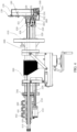
- the hollow linear propelling component 500 includes an extendable-contractile tube 510, a support 520, a power structure 540, a third driving gear 560, a third driven gear 570, a threaded shaft 580, and a nut 590.
- the support 520 is provided with a slide rail 521; a slide plate 530 is slidaly disposed on the slide rail 521; and the nut 590 is provided on the slide plate 530.
- the third driven gear 570 is rotatably disposed on the support 520 and connected to one end of the threaded shaft 580, and another end of the threaded shaft 580 is rotatably disposed in the nut 590.
- the power structure 540 is arranged on the support 520 and connected to the third driving gear 560 to drive the third driving gear 560 to rotate.
- the third driving gear 560 meshes with the third driven gear 570.
- a moving process of the hollow linear propelling component 500 is as follows: the power structure 540 drives the third driving gear 560 to rotate, thereby driving the third driven gear 570 to rotate, forcing the nut 590 to move over the threaded shaft 580, and further driving the slide plate 530 to move on the slide rail 521.
- Two ends of the extendable-contractile tube 510 each are provided with a second adapter flange 511.
- One end of the extendable-contractile tube 510 is connected to the support 520 by one second adapter flange 511, and another end of the extendable-contractile tube 510 is attached to the slide plate 530 by another second adapter flange 511.
- the extendable-contractile tube 510 is sleeved over the outer tube 420, and the two second adapter flanges 511 are connected to the connecting flange 600 and the first adapter flange 700 respectively.
- the power structure 540 drives the third driving gear 560 to rotate, thereby driving the third driven gear 570 to rotate, and further driving the threaded shaft 580 to rotate.
- the nut 590 is arranged on the slide plate 530, and the slide plate 530 is slidably arranged on the slide rail 521 of the support 520, therefore the nut 590 moves along the axial direction of the threaded shaft 580, thereby forcing the slide plate 530 to move along the slide rail 521 of the support 520, forcing the extendable-contractile tube 510 to expand and contract, and further driving the first adapter flange 700 to move relative to the connecting flange 600, so that the cold rod 400 moves, and finally the testing chamber 100 moves in the ultra-vacuum test system.
- the power structure 540 can include a hand wheel, and the hand wheel drives the third driving gear 560 to rotate.
- a positioning member 550 can be disposed at an output shaft of the hand wheel to control the rotation of the output shaft.
- the power structure 540 can also be a stepper motor, and the stepper motor drives the third driving gear 560 to rotate. The stepper motor stops operating when the testing chamber 100 moves to the designated position.
- the connecting flange 600 can also be provided with a pipe body 620 for observing, illuminating, or leading out signal lines.
- the pipe body 620 can be provided with a second small flange 630 for connecting external device.
- the outer surface of the testing chamber 100 can also be provided with a sample transfer guiding groove 130.
- the sample transfer guiding groove 130 is configured to cooperate with an external guide rail and functions as a guide during a transfer of the sample, thereby reducing the influence of processing errors of parts and the influence of shakes of the front end of the sample transfer rod when the sample is transferred over a long distance.
- the in-situ testing device 10 when it is necessary for the tester to test the sample in different test environments, or when the sample is to be placed in the test environment where the optical observation method cannot be adopted, the in-situ testing device 10 can be installed in the ultra-vacuum test system.
- the installation mode is various.
- a square chamber can be specically made according to the requirements of those skilled in the art, and a plurality of flanges that communicate with other components in the ultra-vacuum test system can be arranged on the square chamber.
- the testing chamber 100 is placed inside the square chamber, and then the connecting flange 600 is fixedly connected to the square chamber, so that the testing chamber 100 is installed inside the square chamber.
- Testing equipement such as the Dewar
- the sample transportation line of the ultra-vacuum test system is disposed above the testing chamber 100.
- the sample and the probe can be placed inside the measuring head 800.
- the hollow linear propelling component 500 drives the testing chamber 100 to move to a first position.
- the drive mechanism 200 opens the shielding door 120; then the measuring head 800 is placed into the testing chamber 100; then the drive mechanism 200 closes the shielding door 120.
- the measuring head 800 is fixed in the testing chamber 100 by the locking structure 300; at this time, the first optical observation hole 110 and the second optical observation hole 810 correspond to each other.
- the tester tests the sample and obtains related data by means of the optical observation method.
- the hollow linear propelling component 500 drives the testing chamber 100 to move to a second position, that is, the testing chamber 100 is moved to a position above the testing equipment (such as the Dewar) with a different detecting environment.
- the drive mechanism 200 opens the shielding door 120; the locking structure 300 releases the measuring head 800; then the measuring head 800 is placed to the designated position of the testing equipement (such as the Dewar) having the different test environment by the transportation device in the ultra-vacuum test system.
Landscapes
- Physics & Mathematics (AREA)
- General Physics & Mathematics (AREA)
- Measurement Of Length, Angles, Or The Like Using Electric Or Magnetic Means (AREA)
- Testing Resistance To Weather, Investigating Materials By Mechanical Methods (AREA)
- Testing Electric Properties And Detecting Electric Faults (AREA)
Claims (14)
- Dispositif de test in situ utilisé dans un système de test à ultravide, caractérisé en ce qu'il comprend :une chambre de test (100) installée dans le système de test à ultravide et disposée sur une ligne de transport d'échantillons du système à ultravide, la chambre de test (100) étant pourvue d'un premier trou d'observation optique (110) et d'une porte de protection (120) reliée de manière rotative ou coulissante à la chambre de test (100) ;une tête de mesure (800) pouvant être connectée à la chambre de test (100) et pouvant être insérée dans la chambre de test (100) par un dispositif de transport de la ligne de transport d'échantillons, la tête de mesure (800) étant pourvue d'un deuxième trou d'observation optique (810) de sorte que la position du deuxième trou d'observation (810) soit alignée avec la position du premier trou d'observation optique (110) lorsque la tête de mesure (800) est placée dans la chambre de test (100), la chambre de test (100) étant pourvue d'une ouverture permettant le passage de la tête de mesure (800) ;un mécanisme d'entraînement (200) connecté à la porte de protection (120), et conçu pour entraîner la porte de protection (120) en mouvement par rapport à la chambre de test (100), afin d'ouvrir ou de couvrir l'ouverture, en ouvrant ou fermant ainsi la chambre de test (100) ;un échantillon et une sonde étant placés dans la tête de mesure (800), l'échantillon étant aligné avec la sonde par observation optique, le dispositif de test in situ étant conçu pour réaliser un test préliminaire afin de s'assurer que les propriétés électriques de l'échantillon sont correctes après l'alignement ; etune première plaque d'adaptation d'électrode (820) disposée à une extrémité inférieure de la tête de mesure (800) ; et dans lequella chambre de test (100) est pourvue d'une base d'électrode (140) assemblée en opposition à la première plaque d'adaptation d'électrode (820) ;une pluralité de rainures sont disposées de manière asymétrique sur la base d'électrode (140) ;une pluralité de protubérances (821) correspondant chacune à la pluralité de rainures sont disposées à l'extrémité inférieure de la tête de mesure (800) ;la pluralité de rainures s'ajustent à la pluralité de protubérances (821) ; etla première plaque d'adaptation d'électrode (820) est alignée avec la base d'électrode (140).
- Dispositif de test in situ selon la revendication 1, dans lequel :le mécanisme d'entraînement (200) comprend une première unité de puissance (210) et une première structure de transmission ;la première unité de puissance (210) est connectée à la première structure de transmission ; etla première structure de transmission est connectée à la porte de protection (120) et est conçue pour entraîner la porte de protection (120).
- Dispositif de test in situ selon la revendication 2, dans lequel :l'ouverture s'étend d'une extrémité de la chambre de test (100) à une paroi latérale de la chambre de test (100) ;la porte de protection (120) est en forme de L ; etun bord de la porte de protection (120) est relié de manière rotative à la paroi latérale de la chambre de test (100).
- Dispositif de test in situ selon la revendication 3, dans lequel :la première structure de transmission comprend une première roue menante (230) et une première roue menée (240) ;la porte de protection (120) est pourvue d'un axe de porte (121) ;l'axe de porte (121) est relié de manière rotative à la chambre de test (100) ;la première roue menée (240) est enfilée sur l'axe de porte (121) ;la première unité de puissance (210) est un premier organe rotatif par force magnétique ;le premier organe rotatif par force magnétique est connecté à la première roue menante (230) par une première tige longue (220) ; etla première roue menante (230) s'engrène avec la première roue menée (240).
- Dispositif de test in situ selon la revendication 1, comprenant en outre une base d'installation (900), dans lequel :la chambre de test (100) est disposée sur la base d'installation (900) et un fond de la chambre de test (100) comporte un trou traversant ;une structure de verrouillage (300) est disposée sur la base d'installation (900) et sous le trou traversant de la chambre de test (100) ; etune structure d'interférence est disposée sur la tête de mesure (800) et s'ajuste à la structure de verrouillage (300) afin de fixer la tête de mesure (800) à l'intérieur de la chambre de test (100).
- Dispositif de test in situ selon la revendication 5, dans lequel :la structure de verrouillage (300) comprend une deuxième unité de puissance (310), une deuxième structure de transmission et une tige filetée (350) ;la tige filetée (350) est disposée sur la base d'installation (900) et s'étend dans la chambre de test (100) à travers le trou traversant ;la structure d'interférence comprend un trou fileté disposé sur un fond de la tête de mesure (800) et s'ajustant à la tige filetée (350) ; etla deuxième unité de puissance (310) est connectée à la tige filetée (350) par le biais de la deuxième structure de transmission et conçue pour entraîner la tige filetée (350) à se visser dans le trou fileté, fixant ainsi la tête de mesure (800) à l'intérieur de la chambre de test (100).
- Dispositif de test in situ selon la revendication 6, dans lequel :la deuxième structure de transmission comprend une deuxième roue menante (330) et une deuxième roue menée (340) ;la deuxième roue menée (340) est disposée de manière rotative dans la base d'installation (900) ;la deuxième roue menée (340) est connectée à la tige filetée (350) ;la deuxième unité de puissance (310) est un deuxième organe rotatif par force magnétique ;le deuxième organe rotatif par force magnétique est connecté à la deuxième roue menante (330) par une deuxième tige longue (320) ; etla deuxième roue menante (330) s'engrène avec la deuxième roue menée (340).
- Dispositif de test in situ selon la revendication 7, dans lequel :la tige filetée (350) comprend une première partie (351), une deuxième partie (353) et un élément élastique (354) ;la première partie (351) est en forme de tige et comprend une portion filetée à une extrémité supérieure et une portion cylindrique à une extrémité inférieure ;des surfaces de restriction de position (352) sont disposées sur les parois latérales opposées de la portion cylindrique ;la deuxième partie (353) est connectée à la deuxième roue menée (340) ;la deuxième partie (353) possède un trou de réception destiné à recevoir la portion cylindrique ;l'élément élastique (354) est disposé à l'intérieur du trou de réception et s'appuie contre la portion cylindrique ;un trou d'insertion est disposé dans une paroi latérale du trou de réception et pénètre dans cette paroi ; etun élément de restriction est configuré pour être inséré dans le trou d'insertion et s'appuie contre les surfaces de restriction de position (352) de sorte que la première partie (351) est empêchée de tourner par rapport à la deuxième partie (353).
- Dispositif de test in situ selon la revendication 1, comprenant en outre une tige froide (400) comprenant un tube intérieur (410) et un tube extérieur (420) disposés de façon concentrique ; etun composant de refroidissement (430) disposé à une extrémité de la tige froide (400) ; le tube intérieur (410) et le tube extérieur (420) communiquant par l'intermédiaire du composant de refroidissement (430) ;le composant de refroidissement (430) étant connecté à la chambre de test (100), et une autre extrémité de la tige froide (400), qui est éloignée du composant de refroidissement (430), communiquant avec un dispositif de refroidissement externe afin de permettre au réfrigérant de s'écouler dans le tube intérieur (410) et de sortir du tube extérieur (420), réduisant ainsi la température de la tête de mesure (800).
- Dispositif de test in situ selon la revendication 9, comprenant en outre :une plaque de connexion (170) connectée à la chambre de test (100), la plaque de connexion (170) et le composant de refroidissement (430) étant pourvus d'une pluralité de troisièmes trous filetés en correspondance les uns des autres ;une deuxième plaque d'adaptation d'électrode (171) connectée à un côté de la plaque de connexion (170), une troisième plaque d'adaptation d'électrode (150) étant disposée sur une paroi latérale de la chambre de test (100) et correspondant à la deuxième plaque d'adaptation d'électrode (171) ; etun premier élément de support (450) enfilé sur le tube extérieur (420), le premier élément de support (450) étant configuré pour supporter la tige froide (400).
- Dispositif de test in situ selon la revendication 9, comprenant en outre une bride de connexion (600) et un composant de propulsion linéaire creux (500), qui sont enfilés sur le tube extérieur (420) ;une première extrémité de la bride de connexion (600) étant pourvue d'un deuxième élément de support (610) ;le deuxième élément de support (610) étant pourvu d'un premier trou de tige permettant le passage de la tige froide (400) ;la première extrémité de la bride de connexion (600) étant configurée pour être connectée à un composant fixe externe ;une première extrémité du composant de propulsion linéaire creux (500) étant connectée à une deuxième extrémité de la bride de connexion (600), et la deuxième extrémité de la bride de connexion (600) étant éloignée du deuxième élément de support (610) ;une deuxième extrémité du composant de propulsion linéaire creux (500) étant connectée à la tige froide (400) ; etle composant de propulsion linéaire creux (500) étant configuré pour entraîner la tige froide (400) à se déplacer, entraînant ainsi le déplacement de la chambre de test (100).
- Dispositif de test in situ selon la revendication 11, comprenant en outre une première bride d'adaptation (700) connectée à la deuxième extrémité du composant de propulsion linéaire creux (500),la deuxième extrémité étant éloignée de la bride de connexion (600) ;la tige froide (400) étant installée sur la première bride d'adaptation (700) ; etle composant de propulsion linéaire creux (500) étant connecté à la tige froide (400) par l'intermédiaire de la première bride d'adaptation (700).
- Dispositif de test in situ selon la revendication 12, comprenant en outre :un tube de câblage (440) enfilé sur le tube extérieur (420), une extrémité du tube de câblage (440) étant connectée à la première bride d'adaptation (700), et une autre extrémité du tube de câblage (440) étant soudée au tube extérieur (420) ;plusieurs tubes filetés (441) disposés sur le tube de câblage (440), chaque tube fileté (441) communiquant avec le tube de câblage (440) ; etplusieurs premières petites brides (442) respectivement disposées sur les extrémités des plusieurs tubes filetés (441) éloignées du tube de câblage (440), les plusieurs premières petites brides (442) étant configurées pour se connecter à des dispositifs externes ;les parois intérieures du tube de câblage (440), du composant de propulsion linéaire creux (500), de la bride de connexion (600) et de la première bride d'adaptation (700) étant espacées de la paroi extérieure du tube extérieur (420) afin de former un espace de réception pour des câbles.
- Dispositif de test in situ selon la revendication 11, dans lequel :le composant de propulsion linéaire creux (500) comprend un tube télescopique (510), un support (520), une structure d'alimentation (540), une troisième roue menante (560), une troisième roue menée (570), un axe fileté (580) et un écrou (590) ;le support (520) étant pourvu d'un rail de glissement (521) ;une plaque de glissement (530) étant disposée coulissante sur le rail de glissement (521) ;l'écrou (590) étant disposé sur la plaque de glissement (530) ;la troisième roue menée (570) étant disposée de manière rotative sur le support (520) et connectée à une extrémité de l'axe fileté (580) ;une autre extrémité de l'axe fileté (580) étant disposée de manière rotative dans l'écrou (590) ;la structure d'alimentation (540) étant disposée sur le support (520) et connectée à la troisième roue menante (560) pour entraîner en rotation la troisième roue menante (560) ;la troisième roue menante (560) s'engrenant avec la troisième roue menée (570) ;deux extrémités du tube télescopique (510) étant pourvues chacune d'une deuxième bride d'adaptation (511) ;une extrémité du tube télescopique (510) étant fixée au support (520) par l'intermédiaire d'une deuxième bride d'adaptation (511), et une autre extrémité du tube télescopique (510) étant fixée à la plaque de glissement (530) par une autre deuxième bride d'adaptation (511) ; etle tube télescopique (510) est enfilé sur le tube extérieur (420), et les deux deuxièmes brides d'adaptation (511) sont connectées à la bride de connexion (600) et à la première bride d'adaptation (700) respectivement.
Applications Claiming Priority (2)
| Application Number | Priority Date | Filing Date | Title |
|---|---|---|---|
| CN201810602650.1A CN108445330B (zh) | 2018-06-12 | 2018-06-12 | 原位置检测装置 |
| PCT/CN2018/092909 WO2019237430A1 (fr) | 2018-06-12 | 2018-06-26 | Dispositif de détection de position de maison |
Publications (4)
| Publication Number | Publication Date |
|---|---|
| EP3809147A1 EP3809147A1 (fr) | 2021-04-21 |
| EP3809147A4 EP3809147A4 (fr) | 2021-07-28 |
| EP3809147B1 true EP3809147B1 (fr) | 2025-06-04 |
| EP3809147C0 EP3809147C0 (fr) | 2025-06-04 |
Family
ID=63206252
Family Applications (1)
| Application Number | Title | Priority Date | Filing Date |
|---|---|---|---|
| EP18922778.8A Active EP3809147B1 (fr) | 2018-06-12 | 2018-06-26 | Dispositif de test in-situ utilisé dans un système ultravide |
Country Status (4)
| Country | Link |
|---|---|
| US (1) | US11385256B2 (fr) |
| EP (1) | EP3809147B1 (fr) |
| CN (1) | CN108445330B (fr) |
| WO (1) | WO2019237430A1 (fr) |
Families Citing this family (7)
| Publication number | Priority date | Publication date | Assignee | Title |
|---|---|---|---|---|
| CN113432962B (zh) * | 2021-06-15 | 2022-11-22 | 唐山学院 | 一种塑料提手折弯检测装置及其使用方法 |
| CN114113976A (zh) * | 2021-11-07 | 2022-03-01 | 武汉宇隆光电科技有限公司 | 一种pcba电路板多项功能测试装置 |
| CN114252474B (zh) * | 2021-12-22 | 2024-11-01 | 赛迈科先进材料股份有限公司 | 一种高效率石墨热膨胀测试仪 |
| CN116087102B (zh) * | 2023-01-13 | 2023-11-03 | 中国科学院空间应用工程与技术中心 | 一种冰卫星和地外海洋极端环境模拟系统实验装置 |
| CN116165472B (zh) * | 2023-04-22 | 2023-07-04 | 深圳市森美协尔科技有限公司 | 一种低温探针测试设备 |
| CN117471258B (zh) * | 2023-11-16 | 2024-05-28 | 河北如电电气设备有限公司 | 一种电力设备故障检测装置 |
| CN120427351B (zh) * | 2025-07-07 | 2025-09-26 | 中国地质科学院地质力学研究所 | 一种建筑结构面测试样品的制作模具 |
Citations (2)
| Publication number | Priority date | Publication date | Assignee | Title |
|---|---|---|---|---|
| CN104749470A (zh) * | 2015-04-13 | 2015-07-01 | 清华大学 | 输运性质测量系统 |
| EP2673901B1 (fr) * | 2011-02-10 | 2021-01-06 | Bruker Nano, Inc. | Système de test nanomécanique |
Family Cites Families (10)
| Publication number | Priority date | Publication date | Assignee | Title |
|---|---|---|---|---|
| JP4526626B2 (ja) * | 1999-12-20 | 2010-08-18 | 独立行政法人科学技術振興機構 | 電気特性評価装置 |
| NL1026542C2 (nl) * | 2004-07-01 | 2006-01-03 | Brabantia Nederland Bv | Pedaalemmer. |
| CN2837831Y (zh) * | 2005-11-11 | 2006-11-15 | 中国科学院物理研究所 | 新型超高真空原位生长、表征和测试系统 |
| JP2009152087A (ja) * | 2007-12-21 | 2009-07-09 | Jeol Ltd | 透過電子顕微鏡 |
| KR101592575B1 (ko) * | 2009-03-20 | 2016-02-05 | 엘지전자 주식회사 | 냉장고 |
| CN101846635B (zh) * | 2010-05-07 | 2012-05-23 | 中国科学院半导体研究所 | 一种超高真空多功能综合测试系统 |
| CN103792443B (zh) * | 2012-11-01 | 2016-09-28 | 国家纳米科学中心 | 探针台、有机薄膜器件的制备与测试集成系统及其方法 |
| CN104291017B (zh) * | 2014-10-25 | 2017-07-28 | 中国科学技术大学 | 一种具有原位测量效果的可拆除式独立真空腔体 |
| CN107525846B (zh) * | 2017-10-11 | 2024-06-21 | 北京大学 | 一种超高真空兼容的低温强磁场原位输运装置 |
| CN208367116U (zh) * | 2018-06-12 | 2019-01-11 | 清华大学 | 原位置检测装置 |
-
2018
- 2018-06-12 CN CN201810602650.1A patent/CN108445330B/zh active Active
- 2018-06-26 EP EP18922778.8A patent/EP3809147B1/fr active Active
- 2018-06-26 WO PCT/CN2018/092909 patent/WO2019237430A1/fr not_active Ceased
-
2020
- 2020-12-14 US US17/121,589 patent/US11385256B2/en active Active
Patent Citations (2)
| Publication number | Priority date | Publication date | Assignee | Title |
|---|---|---|---|---|
| EP2673901B1 (fr) * | 2011-02-10 | 2021-01-06 | Bruker Nano, Inc. | Système de test nanomécanique |
| CN104749470A (zh) * | 2015-04-13 | 2015-07-01 | 清华大学 | 输运性质测量系统 |
Also Published As
| Publication number | Publication date |
|---|---|
| CN108445330A (zh) | 2018-08-24 |
| WO2019237430A1 (fr) | 2019-12-19 |
| EP3809147A1 (fr) | 2021-04-21 |
| EP3809147C0 (fr) | 2025-06-04 |
| EP3809147A4 (fr) | 2021-07-28 |
| CN108445330B (zh) | 2024-04-30 |
| US11385256B2 (en) | 2022-07-12 |
| US20210096155A1 (en) | 2021-04-01 |
Similar Documents
| Publication | Publication Date | Title |
|---|---|---|
| EP3809147B1 (fr) | Dispositif de test in-situ utilisé dans un système ultravide | |
| KR100247329B1 (ko) | 케이블 피벗을 갖춘 장치 시험 시스템 및 그의 설치방법 | |
| US20240133906A1 (en) | Detachable modularized test platform | |
| CN113720873B (zh) | 冷媒传输耦合装置测试系统 | |
| CN114062395B (zh) | 一种用于高温管道探伤的α射线无损检测装置 | |
| CN208367116U (zh) | 原位置检测装置 | |
| US7570057B2 (en) | NMR spectrometer | |
| CN214895700U (zh) | 电池绝缘检测工装及检测设备 | |
| CN112615323B (zh) | 高温超导电缆线路的杜瓦伸缩可调装置 | |
| CN113932843A (zh) | 对温湿度及压力进行控制的传感器测试腔体及应用方法 | |
| JP2953637B2 (ja) | 回転自在なプローブのための可撓性送出し装置 | |
| US20230184854A1 (en) | Fastening an nmr probe head to the shim tube end of the nmr magnet with automatable functional connections | |
| CN117915538A (zh) | 一种新型的、等时性质子回旋加速器专用的径向探针装置 | |
| US5347219A (en) | Resonator arrangement for electron spin resonance spectroscopy | |
| CN221976317U (zh) | 一种光纤测温装置 | |
| CN215985824U (zh) | 冷媒传输耦合装置测试系统 | |
| US6771062B1 (en) | Apparatus for supporting and manipulating a testhead in an automatic test equipment system | |
| CN224152384U (zh) | 一种自动换样样品杆及恒温器 | |
| CN215963611U (zh) | 用于冷媒传输耦合装置测试的旋转真空仓 | |
| CN118817834A (zh) | 控制棒驱动机构管座与贯穿件对接焊缝自动超声扫查系统 | |
| CN109932610A (zh) | 用于电缆中间接头检测的检测装置及其辅助定位机构 | |
| CN220395235U (zh) | 保温棉施工辅助工具 | |
| CN224004860U (zh) | 一种电缆弯曲试验机 | |
| CN115764728B (zh) | 电缆安装的固定装置 | |
| CA1205584A (fr) | Methode et dispositif d'inspection d'un tube sous pression dans un reacteur |
Legal Events
| Date | Code | Title | Description |
|---|---|---|---|
| STAA | Information on the status of an ep patent application or granted ep patent |
Free format text: STATUS: THE INTERNATIONAL PUBLICATION HAS BEEN MADE |
|
| PUAI | Public reference made under article 153(3) epc to a published international application that has entered the european phase |
Free format text: ORIGINAL CODE: 0009012 |
|
| STAA | Information on the status of an ep patent application or granted ep patent |
Free format text: STATUS: REQUEST FOR EXAMINATION WAS MADE |
|
| 17P | Request for examination filed |
Effective date: 20210107 |
|
| AK | Designated contracting states |
Kind code of ref document: A1 Designated state(s): AL AT BE BG CH CY CZ DE DK EE ES FI FR GB GR HR HU IE IS IT LI LT LU LV MC MK MT NL NO PL PT RO RS SE SI SK SM TR |
|
| AX | Request for extension of the european patent |
Extension state: BA ME |
|
| A4 | Supplementary search report drawn up and despatched |
Effective date: 20210629 |
|
| RIC1 | Information provided on ipc code assigned before grant |
Ipc: G01R 31/00 20060101AFI20210623BHEP |
|
| DAV | Request for validation of the european patent (deleted) | ||
| DAX | Request for extension of the european patent (deleted) | ||
| STAA | Information on the status of an ep patent application or granted ep patent |
Free format text: STATUS: EXAMINATION IS IN PROGRESS |
|
| 17Q | First examination report despatched |
Effective date: 20230322 |
|
| GRAP | Despatch of communication of intention to grant a patent |
Free format text: ORIGINAL CODE: EPIDOSNIGR1 |
|
| STAA | Information on the status of an ep patent application or granted ep patent |
Free format text: STATUS: GRANT OF PATENT IS INTENDED |
|
| INTG | Intention to grant announced |
Effective date: 20241212 |
|
| GRAS | Grant fee paid |
Free format text: ORIGINAL CODE: EPIDOSNIGR3 |
|
| GRAA | (expected) grant |
Free format text: ORIGINAL CODE: 0009210 |
|
| STAA | Information on the status of an ep patent application or granted ep patent |
Free format text: STATUS: THE PATENT HAS BEEN GRANTED |
|
| AK | Designated contracting states |
Kind code of ref document: B1 Designated state(s): AL AT BE BG CH CY CZ DE DK EE ES FI FR GB GR HR HU IE IS IT LI LT LU LV MC MK MT NL NO PL PT RO RS SE SI SK SM TR |
|
| REG | Reference to a national code |
Ref country code: GB Ref legal event code: FG4D |
|
| REG | Reference to a national code |
Ref country code: CH Ref legal event code: EP |
|
| REG | Reference to a national code |
Ref country code: DE Ref legal event code: R096 Ref document number: 602018082490 Country of ref document: DE |
|
| REG | Reference to a national code |
Ref country code: IE Ref legal event code: FG4D |
|
| U01 | Request for unitary effect filed |
Effective date: 20250702 |
|
| U07 | Unitary effect registered |
Designated state(s): AT BE BG DE DK EE FI FR IT LT LU LV MT NL PT RO SE SI Effective date: 20250708 |
|
| U20 | Renewal fee for the european patent with unitary effect paid |
Year of fee payment: 8 Effective date: 20250827 |
|
| PG25 | Lapsed in a contracting state [announced via postgrant information from national office to epo] |
Ref country code: ES Free format text: LAPSE BECAUSE OF FAILURE TO SUBMIT A TRANSLATION OF THE DESCRIPTION OR TO PAY THE FEE WITHIN THE PRESCRIBED TIME-LIMIT Effective date: 20250604 |
|
| PG25 | Lapsed in a contracting state [announced via postgrant information from national office to epo] |
Ref country code: GR Free format text: LAPSE BECAUSE OF FAILURE TO SUBMIT A TRANSLATION OF THE DESCRIPTION OR TO PAY THE FEE WITHIN THE PRESCRIBED TIME-LIMIT Effective date: 20250905 Ref country code: NO Free format text: LAPSE BECAUSE OF FAILURE TO SUBMIT A TRANSLATION OF THE DESCRIPTION OR TO PAY THE FEE WITHIN THE PRESCRIBED TIME-LIMIT Effective date: 20250904 |
|
| PG25 | Lapsed in a contracting state [announced via postgrant information from national office to epo] |
Ref country code: PL Free format text: LAPSE BECAUSE OF FAILURE TO SUBMIT A TRANSLATION OF THE DESCRIPTION OR TO PAY THE FEE WITHIN THE PRESCRIBED TIME-LIMIT Effective date: 20250604 |
|
| PG25 | Lapsed in a contracting state [announced via postgrant information from national office to epo] |
Ref country code: HR Free format text: LAPSE BECAUSE OF FAILURE TO SUBMIT A TRANSLATION OF THE DESCRIPTION OR TO PAY THE FEE WITHIN THE PRESCRIBED TIME-LIMIT Effective date: 20250604 |
|
| PG25 | Lapsed in a contracting state [announced via postgrant information from national office to epo] |
Ref country code: RS Free format text: LAPSE BECAUSE OF FAILURE TO SUBMIT A TRANSLATION OF THE DESCRIPTION OR TO PAY THE FEE WITHIN THE PRESCRIBED TIME-LIMIT Effective date: 20250904 |
|
| PG25 | Lapsed in a contracting state [announced via postgrant information from national office to epo] |
Ref country code: IS Free format text: LAPSE BECAUSE OF FAILURE TO SUBMIT A TRANSLATION OF THE DESCRIPTION OR TO PAY THE FEE WITHIN THE PRESCRIBED TIME-LIMIT Effective date: 20251004 |
|
| PG25 | Lapsed in a contracting state [announced via postgrant information from national office to epo] |
Ref country code: SM Free format text: LAPSE BECAUSE OF FAILURE TO SUBMIT A TRANSLATION OF THE DESCRIPTION OR TO PAY THE FEE WITHIN THE PRESCRIBED TIME-LIMIT Effective date: 20250604 |
|
| PG25 | Lapsed in a contracting state [announced via postgrant information from national office to epo] |
Ref country code: CZ Free format text: LAPSE BECAUSE OF FAILURE TO SUBMIT A TRANSLATION OF THE DESCRIPTION OR TO PAY THE FEE WITHIN THE PRESCRIBED TIME-LIMIT Effective date: 20250604 |
|
| PG25 | Lapsed in a contracting state [announced via postgrant information from national office to epo] |
Ref country code: SK Free format text: LAPSE BECAUSE OF FAILURE TO SUBMIT A TRANSLATION OF THE DESCRIPTION OR TO PAY THE FEE WITHIN THE PRESCRIBED TIME-LIMIT Effective date: 20250604 |
|
| REG | Reference to a national code |
Ref country code: CH Ref legal event code: H13 Free format text: ST27 STATUS EVENT CODE: U-0-0-H10-H13 (AS PROVIDED BY THE NATIONAL OFFICE) Effective date: 20260127 |
|
| PG25 | Lapsed in a contracting state [announced via postgrant information from national office to epo] |
Ref country code: MC Free format text: LAPSE BECAUSE OF FAILURE TO SUBMIT A TRANSLATION OF THE DESCRIPTION OR TO PAY THE FEE WITHIN THE PRESCRIBED TIME-LIMIT Effective date: 20250604 |
|
| PLBE | No opposition filed within time limit |
Free format text: ORIGINAL CODE: 0009261 |
|
| STAA | Information on the status of an ep patent application or granted ep patent |
Free format text: STATUS: NO OPPOSITION FILED WITHIN TIME LIMIT |
|
| PG25 | Lapsed in a contracting state [announced via postgrant information from national office to epo] |
Ref country code: IE Free format text: LAPSE BECAUSE OF NON-PAYMENT OF DUE FEES Effective date: 20250626 |
|
| REG | Reference to a national code |
Ref country code: CH Ref legal event code: L10 Free format text: ST27 STATUS EVENT CODE: U-0-0-L10-L00 (AS PROVIDED BY THE NATIONAL OFFICE) Effective date: 20260416 |
|
| PG25 | Lapsed in a contracting state [announced via postgrant information from national office to epo] |
Ref country code: CH Free format text: LAPSE BECAUSE OF NON-PAYMENT OF DUE FEES Effective date: 20250630 |