EP3809151B1 - Procédé mis en oeuvre par ordinateur permettant de fournir une séquence de commande et procédé de détection des données de mesure à l'aide d'un dispositif de résonance magnétique - Google Patents
Procédé mis en oeuvre par ordinateur permettant de fournir une séquence de commande et procédé de détection des données de mesure à l'aide d'un dispositif de résonance magnétique Download PDFInfo
- Publication number
- EP3809151B1 EP3809151B1 EP19202976.7A EP19202976A EP3809151B1 EP 3809151 B1 EP3809151 B1 EP 3809151B1 EP 19202976 A EP19202976 A EP 19202976A EP 3809151 B1 EP3809151 B1 EP 3809151B1
- Authority
- EP
- European Patent Office
- Prior art keywords
- energy input
- magnetic resonance
- under investigation
- computer
- actuation sequence
- Prior art date
- Legal status (The legal status is an assumption and is not a legal conclusion. Google has not performed a legal analysis and makes no representation as to the accuracy of the status listed.)
- Active
Links
Images


Classifications
-
- G—PHYSICS
- G01—MEASURING; TESTING
- G01R—MEASURING ELECTRIC VARIABLES; MEASURING MAGNETIC VARIABLES
- G01R33/00—Arrangements or instruments for measuring magnetic variables
- G01R33/20—Arrangements or instruments for measuring magnetic variables involving magnetic resonance
- G01R33/44—Arrangements or instruments for measuring magnetic variables involving magnetic resonance using nuclear magnetic resonance [NMR]
- G01R33/48—NMR imaging systems
- G01R33/54—Signal processing systems, e.g. using pulse sequences ; Generation or control of pulse sequences; Operator console
- G01R33/56—Image enhancement or correction, e.g. subtraction or averaging techniques, e.g. improvement of signal-to-noise ratio and resolution
- G01R33/565—Correction of image distortions, e.g. due to magnetic field inhomogeneities
- G01R33/5659—Correction of image distortions, e.g. due to magnetic field inhomogeneities caused by a distortion of the RF magnetic field, e.g. spatial inhomogeneities of the RF magnetic field
-
- G—PHYSICS
- G01—MEASURING; TESTING
- G01R—MEASURING ELECTRIC VARIABLES; MEASURING MAGNETIC VARIABLES
- G01R33/00—Arrangements or instruments for measuring magnetic variables
- G01R33/20—Arrangements or instruments for measuring magnetic variables involving magnetic resonance
- G01R33/44—Arrangements or instruments for measuring magnetic variables involving magnetic resonance using nuclear magnetic resonance [NMR]
- G01R33/48—NMR imaging systems
- G01R33/54—Signal processing systems, e.g. using pulse sequences ; Generation or control of pulse sequences; Operator console
- G01R33/543—Control of the operation of the MR system, e.g. setting of acquisition parameters prior to or during MR data acquisition, dynamic shimming, use of one or more scout images for scan plane prescription
-
- G—PHYSICS
- G01—MEASURING; TESTING
- G01R—MEASURING ELECTRIC VARIABLES; MEASURING MAGNETIC VARIABLES
- G01R33/00—Arrangements or instruments for measuring magnetic variables
- G01R33/20—Arrangements or instruments for measuring magnetic variables involving magnetic resonance
- G01R33/24—Arrangements or instruments for measuring magnetic variables involving magnetic resonance for measuring direction or magnitude of magnetic fields or magnetic flux
- G01R33/243—Spatial mapping of the polarizing magnetic field
-
- G—PHYSICS
- G01—MEASURING; TESTING
- G01R—MEASURING ELECTRIC VARIABLES; MEASURING MAGNETIC VARIABLES
- G01R33/00—Arrangements or instruments for measuring magnetic variables
- G01R33/20—Arrangements or instruments for measuring magnetic variables involving magnetic resonance
- G01R33/24—Arrangements or instruments for measuring magnetic variables involving magnetic resonance for measuring direction or magnitude of magnetic fields or magnetic flux
- G01R33/246—Spatial mapping of the RF magnetic field B1
-
- G—PHYSICS
- G01—MEASURING; TESTING
- G01R—MEASURING ELECTRIC VARIABLES; MEASURING MAGNETIC VARIABLES
- G01R33/00—Arrangements or instruments for measuring magnetic variables
- G01R33/20—Arrangements or instruments for measuring magnetic variables involving magnetic resonance
- G01R33/28—Details of apparatus provided for in groups G01R33/44 - G01R33/64
- G01R33/38—Systems for generation, homogenisation or stabilisation of the main or gradient magnetic field
- G01R33/385—Systems for generation, homogenisation or stabilisation of the main or gradient magnetic field using gradient magnetic field coils
- G01R33/3852—Gradient amplifiers; means for controlling the application of a gradient magnetic field to the sample, e.g. a gradient signal synthesizer
-
- G—PHYSICS
- G01—MEASURING; TESTING
- G01R—MEASURING ELECTRIC VARIABLES; MEASURING MAGNETIC VARIABLES
- G01R33/00—Arrangements or instruments for measuring magnetic variables
- G01R33/20—Arrangements or instruments for measuring magnetic variables involving magnetic resonance
- G01R33/28—Details of apparatus provided for in groups G01R33/44 - G01R33/64
- G01R33/288—Provisions within MR facilities for enhancing safety during MR, e.g. reduction of the specific absorption rate [SAR], detection of ferromagnetic objects in the scanner room
-
- G—PHYSICS
- G01—MEASURING; TESTING
- G01R—MEASURING ELECTRIC VARIABLES; MEASURING MAGNETIC VARIABLES
- G01R33/00—Arrangements or instruments for measuring magnetic variables
- G01R33/20—Arrangements or instruments for measuring magnetic variables involving magnetic resonance
- G01R33/44—Arrangements or instruments for measuring magnetic variables involving magnetic resonance using nuclear magnetic resonance [NMR]
- G01R33/48—NMR imaging systems
- G01R33/54—Signal processing systems, e.g. using pulse sequences ; Generation or control of pulse sequences; Operator console
- G01R33/56—Image enhancement or correction, e.g. subtraction or averaging techniques, e.g. improvement of signal-to-noise ratio and resolution
- G01R33/561—Image enhancement or correction, e.g. subtraction or averaging techniques, e.g. improvement of signal-to-noise ratio and resolution by reduction of the scanning time, i.e. fast acquiring systems, e.g. using echo-planar pulse sequences
- G01R33/5611—Parallel magnetic resonance imaging, e.g. sensitivity encoding [SENSE], simultaneous acquisition of spatial harmonics [SMASH], unaliasing by Fourier encoding of the overlaps using the temporal dimension [UNFOLD], k-t-broad-use linear acquisition speed-up technique [k-t-BLAST], k-t-SENSE
- G01R33/5612—Parallel RF transmission, i.e. RF pulse transmission using a plurality of independent transmission channels
Definitions
- the invention relates to a computer-implemented method for providing a control sequence to be used, which specifies the respective transmission signals to be emitted by an antenna arrangement of the magnetic resonance device for the acquisition of measurement data of an examination object by a magnetic resonance device for at least one high-frequency transmission channel, in particular for a plurality of high-frequency transmission channels.
- the invention relates to a method for the acquisition of measurement data of an examination object by a magnetic resonance device, a provision and/or magnetic resonance device, a computer program and a computer-readable data carrier.
- a static magnetic flux density of approx. 7 Tesla is used for ultra-high field magnetic resonance imaging.
- Such high field strengths of the main magnetic field B 0 require relatively high-frequency excitation pulses with a frequency of approx. 300 MHz in order to excite spins in the body of the object under examination.
- the wavelength of such an electromagnetic wave is very small in biological tissue, namely in the range of approx. 13 cm.
- the relatively good tissue conductivity for high frequencies and reflections at interfaces between different biological tissues or biological tissue and air can result in strong inhomogeneities in the excitation field. Since high static field strengths of the B 0 field are also used, even relatively small relative differences can lead to large absolute differences in the field strength and thus to significantly different Larmor frequencies between different regions of the object under investigation.
- a transmitting space can be scanned in order to achieve a spatial coding of the B 1 field, i.e. the high-frequency field used for spin excitation.
- This allows a stronger or longer application of the high-frequency field B 1 for areas in which weaker signals are expected.
- SAR specific absorption rates
- SED specific energy doses
- pTx parallel excitation
- the simultaneous control of several such coils with simultaneous or intermediate k-space scanning by controlling gradient coils is also called pTx pulse.
- B 1 shimming With regard to such excitation, static RF shimming or B 1 shimming is closest to clinical applicability.
- individual amplitudes and phases are assigned to each coil in order to homogenize the overall B 1 field generated during excitation.
- the amplitudes and phases can be calculated using the previously acquired transmit coil profiles, i.e. a B 1 map and a B 0 map.
- a potential further improvement can be achieved through dynamic RF shimming or flip angle shimming, which is not currently used for clinical applications.
- a separate pulse shape is calculated for each individual excitation coil and the k-space is simultaneously scanned along a trajectory.
- the trajectory used to scan the k-space is based on the principle of so-called k T points, which is described for example in the article Cloos, MA, et al. (2012), kT-Points: Short three-dimensional tailored RF pulses for flip-angle homogenization over an extended volume, Magnetic Resonance in Medicine 67:72-80 , is discussed.
- a rectangular pulse with a specific amplitude and phase is sent to various calculated points in k-space.
- the disadvantage of using universal pulses, however, is that under given boundary conditions, for example with a maximum permissible specific absorption rate, the same image quality cannot typically be achieved as would be possible with an individually optimized control sequence.
- VOP Virtual Observation Points
- body models are typically used that describe the conductivity and electrical permeability of different body regions.
- An approach to obtain electrical properties of tissue from measurement data of a magnetic resonance device is described in the article Zhang, X., et al. (2013), Complex B1 mapping and electrical properties imaging of the human brain using a 16-channel transceiver coil at 7T, Magnetic Resonance in Medicine 69:1285-1296 , known.
- the patent specification EN 10 2007 013422 B4 describes a method for controlling a magnetic resonance system with a radio-frequency antenna structure and several individually controllable transmission channels.
- the publication US 2018/011155 A1 discloses a method for adjusting RF shimming parameters and, in particular, a technique for improving the homogeneity of a high frequency magnetic field distribution while reducing the amount of absorption of electromagnetic waves in the body tissue.
- the article Van den Bergen et al (2007) 7 T body MRI: B1 shimming with simultaneous SAR reduction, Phys Med Biol 52(17):5429-5441 describes a B1 shimming technique that can simultaneously improve B+1 homogeneity and reduce SAR for whole-body imaging at 7 T.
- the invention is therefore based on the object of specifying a possibility to further improve the achievable image quality in magnetic resonance devices compared to the universal pulses discussed above, while avoiding the need for excessively long measurement or computing times for the individual examination object, so that in particular an examination time in everyday clinical practice is not extended too much.
- the invention is based on the idea of carrying out a large part of the optimization in an upstream optimization process.
- This can be independent of the properties of the examination object and in particular independent of the field distribution maps recorded on the examination object, so that the control sequences can be provided, for example, before the start of the method according to the invention and in particular before any imaging is carried out on the examination object, i.e. for example already during production or as part of a normal update of the magnetic resonance device or another provision device that carries out the computer-implemented method.
- control sequences are provided, from which a control sequence to be used is selected depending on the properties of the object under investigation, namely the field distribution maps.
- the optimization parameter specifies the extent to which the focus of the optimization is on reducing the energy input into the object under investigation on the one hand and on achieving the best possible a target excitation distribution, i.e. a predetermined distribution of flip angles. Based on the properties of the object under investigation, it is then selected which of these Control sequences are particularly well suited for the specific object under investigation.
- the procedure according to the invention allows the control sequence to be used to be selected with relatively little computing effort, for example within 5 or 10 seconds to two minutes, after the control sequences and the field distribution maps have been provided.
- the required field distribution maps can be recorded in a few tens of seconds, for example within 40 seconds.
- the field distribution maps can be recorded and the computer-implemented method can thus be carried out immediately before the control sequence is played out, i.e. the measurement data is recorded, whereby this only leads to an extension of the examination time by one to two minutes, which means that the procedure described can also be used well in everyday clinical practice.
- control sequences can be determined in such a way that they are generated identically apart from the use of a different optimization parameter within the optimization process. In other words, the control sequences can only differ with regard to the value for exactly one optimization parameter.
- the implementation of the optimization process and/or the recording of the field distribution maps can be carried out as preparatory steps for the computer-implemented process, i.e. outside of the process itself, or as part of the process. It is also possible, for example, for the various control sequences or the field distribution maps to be taken from a database, so that the respective determination can begin well before the start of the computer-implemented process.
- the control sequence or the transmission signals can be determined, for example, in such a way that parameters are determined for the respective high-frequency transmission channel that parameterize a pulse shape.
- these parameters can specify a complex envelope for a transmission signal with a given frequency.
- the complex envelope can specify the amplitude and phase of the transmission signal for the respective high-frequency transmission channel continuously or quasi-continuously or discretely for individual points in k-space.
- Transmission can only take place for specific k-space positions, whereby gradient coils can be controlled between the individual transmission processes, in particular by the control sequence, in order to change the k-space position of the excitation.
- Such excitation at selected k-space points is known, for example, from the publication by MA Cloos et al. cited at the beginning.
- the control sequences can particularly preferably be determined by the optimization method in such a way that high-frequency radiation is emitted continuously during the excitation, preferably by all high-frequency transmission channels simultaneously. It is therefore also possible to use control sequences that provide for the emission of high-frequency radiation via at least one or all of the high-frequency transmission channels even when gradient coils are energized to shift the k-space position.
- B 1 maps can be used as field distribution maps, each of which indicates the spatial B 1 field distribution for a specific transmitting coil, i.e. for a specific high-frequency transmitting channel of the antenna arrangement. In other words, these B 1 maps describe the spatial sensitivity of the corresponding transmitting coil.
- a B 0 map can be used, which spatially represents the deviations of the main magnetic field from the actually desired homogeneous field profile. In other words, the B 0 map describes how strongly the Larmor frequency deviates locally from the desired Larmor frequency.
- a preliminary control sequence can be selected from the various control sequences and, depending on the field distribution maps and the preliminary control sequence, an energy input into a selected area of the object under investigation can be predicted when the preliminary control sequence is used to record the measurement data, whereby the control sequence to be used or a new preliminary control sequence is selected from the various control sequences depending on the predicted energy input.
- a preliminary control sequence can only be selected as the control sequence to be used if the predicted energy input is less than a limit value or is within a target or tolerance interval for the energy input.
- An upper limit value can be determined, for example, depending on SAR limits of the International Electrotechnical Commission (IEC) and sequence or protocol parameters of the respective control sequence.
- a target or tolerance interval can be selected so that all energy inputs within this interval are below a defined limit value, but not by more than a certain deviation, for example a specified percentage deviation.
- the control sequence is determined iteratively. For example, if it is determined in the first pass that the preliminary control sequence leads to an energy input which is greater than a limit or outside a
- a new control sequence is selected from the provisional control sequences and the determination of the energy input is repeated. This procedure is repeated until the energy input for the current provisional control sequence is less than the limit value or is within the target or tolerance interval.
- the control sequence for which this is the case is selected as the control sequence to be used.
- the control sequence for which optimal measurement data acquisition is expected can be selected, whereby this can in particular be the measurement sequence with the largest energy input still within the target or tolerance interval.
- An order for the various control sequences can be specified depending on an expected energy input. For example, an energy input into at least one reference examination object, preferably into several reference examination objects, can be predicted for each of the various control sequences. The energy input or the average of these energy inputs can then be used to order the various control sequences according to their expected energy input or according to a parameter that correlates with this. If the energy input predicted for the provisional control sequence lies outside the target or tolerance interval, this makes it possible to determine in which direction of the order the new control sequence or the one to be used is selected, depending on whether it lies above or below this interval. As will be explained in more detail later, the selection can also depend on the magnitude of the deviation.
- a similar procedure is also possible if only an upper limit is specified for the energy input. If the predicted energy input exceeds the limit, a provisional control sequence with a lower energy input can be selected based on the sequence. If the energy input is below the limit, it can be checked, for example, whether this also applies to a new provisional control sequence for which a slightly higher energy input is expected. This can, for example, avoid using a control sequence with an unnecessarily low energy input, which would typically lead to suboptimal quality of the measurement data.
- a control sequence can be selected as a provisional control sequence for which an energy input has been predicted for the reference test object or objects that is within the target or tolerance interval or as close as possible to the limit value. If the energy input for the test object as a function of the field distribution maps is similar to that for the reference test objects, this control sequence can be immediately selected and made available as the control sequence to be used. However, if the energy input predicted as a function of the field distribution maps differs from the energy input expected based on the reference test objects, another of the various control sequences can be selected and tested, as explained above.
- the relevant area can in particular be an area for which the highest energy input is predicted.
- a respective predicted energy input can be determined for several areas of the object under investigation, whereby the control sequence to be used or the new provisional control sequence is selected depending on the predicted energy input in that selected area in which the predicted energy input is the greatest.
- the several areas can, for example, be individual Voxels or connected groups of voxels.
- the individual areas are particularly preferably the virtual observation points discussed at the beginning, as explained in more detail in the article by G. Eichfelder et al. discussed above.
- an upper limit for energy inputs occurring in the assigned area can be determined for each virtual observation point. This upper limit can be predicted in the method according to the invention as the energy input for this area.
- the local fields can be calculated by an electrodynamic simulation using a body model depending on the control signals that are fed to the individual high-frequency transmission channels. This allows an accurate determination of the electric fields and thus of the SED value.
- the field distribution maps can advantageously be used in the method according to the invention to calculate the energy input, i.e. in particular the SED value, for a respective preliminary control sequence.
- ⁇ 0 is the magnetic permeability, which can be at least approximately equated to the permeability of the vacuum.
- the only unknown for calculating the electric fields E and thus also the SED value is the local permittivity ⁇ .
- this can also be determined from the B 1 maps.
- phase information regarding the B 1 fields can be reconstructed without additional measurement effort by solving a system of equations that depends on the B 1 maps determined for the individual high-frequency channels. Since B 1 maps are typically to be determined for each of the high-frequency transmission channels and each receiving antenna anyway, the determination of the energy input, in particular an SED value, for the individual object under investigation is possible without additional measurement effort or generally without modifying the measuring device used.
- the degree to which the optimization focuses on minimizing the energy input on the one hand or on minimizing the deviation on the other is weighted.
- a higher value of the energy input is accepted for some of the control sequences in order to achieve a greater optimization with regard to the deviation.
- the deviation measure can be determined, for example, as the standard deviation between the expected excitation distribution and a target excitation distribution.
- the standard deviation can be calculated jointly for all reference objects under investigation or separately for the individual objects under investigation. In a separate calculation, the sum or average of these standard deviations can then be used as the deviation measure.
- the SED value explained above or another measure for the specific energy dose introduced into a reference object or an area of the reference object can be used as an energy input measure.
- a separate value can first be calculated for each of the objects under investigation and these values can be added together or an average can be formed.
- the reference data sets can each specify a numerical body model for an electrodynamic simulation, but it is also sufficient to specify field distribution maps for the respective reference object under investigation. Determining a control sequence that minimizes the cost function is typically a non-convex optimization problem, so that it can be advantageous within the optimization process can perform the optimization procedure with multiple starting points to enable a robust finding of a global minimum.
- several of the reference examination objects can be taken into account, whereby for each of the reference examination objects and each of the different control sequences, an individual energy input is determined which relates to an expected energy input into the reference area of this reference examination object when using this control sequence, whereby for each of the different control sequences an average of the individual energy inputs is determined and assigned to the optimization parameter used to determine the respective control sequence or to the control sequence itself.
- 10-20 reference examination objects can be taken into account. However, it is possible to take into account a larger or smaller number of reference examination objects.
- a respective expected energy input can be determined for several areas of the respective reference examination object, with the largest of these expected energy inputs being selected as the individual energy input for this control sequence and this reference examination object.
- the area for which the largest energy input is determined is selected as the reference area. Potential hotspots in which a particularly high energy input occurs are thus identified and taken into account. This makes it possible in particular to identify when a certain control sequence leads to a particularly high energy input locally in one or more areas and thus potentially to severe heating.
- a functional relationship between the optimization parameters and the associated mean values are determined, whereby the control sequence to be used and/or the provisional and/or the new provisional control sequence are selected depending on this functional relationship.
- a polynomial relationship can be determined as the functional relationship.
- the functional relationship can be determined, for example, by a fit or a regression analysis. The functional relationship can significantly accelerate the finding of a suitable optimization parameter or a suitable control sequence, particularly when using a relatively large number of different control sequences or values of the optimization parameter.
- an energy input is predicted for a preliminary control sequence that exceeds a target value by a certain offset or scaling factor
- an intermediate value can be calculated that is smaller than the previous target value by this offset or scaling factor and an associated value for the optimization parameter can be determined based on the functional relationship.
- the new preliminary control sequence can then be selected so that its optimization parameter is as close as possible to the optimization parameter determined in this way.
- a suitable control sequence can typically be determined within a few iteration steps.
- the various control sequences each additionally comprise control information for controlling at least one gradient coil to provide a gradient field.
- the control sequences can, for example, each describe a temporal progression of the gradient fields, which is played out synchronously with the high-frequency pulses, i.e. the transmission signals for the high-frequency transmission channels, when the control sequence is used.
- the temporal progression of the gradient fields describes a k-space trajectory for the excitation.
- the combination of gradient fields and high-frequency pulses to achieve a more uniform excitation is well known from the prior art and is intended to cannot be explained in detail. In the simplest case, it would be possible to use the same k-space trajectory for all control sequences. Since the k-space trajectory used or the control information for controlling the at least one gradient coil influences the resulting excitation distribution, corresponding information is also taken into account in the optimization explained above.
- the use of a fixed k-space trajectory can reduce the computational effort for an optimization.
- control sequences with different control information can be advantageous to use different control sequences with different control information to control the at least one gradient coil, in other words control sequences that use different k-space trajectories. This does lead to more free parameters being available during optimization, which can increase the computational effort required for optimization.
- the determination of the various control trajectories by the optimization method in the method according to the invention is independent of data from the specific object under investigation and can therefore be carried out upstream, it is easily possible to carry out an optimization method that requires a great deal of computing power.
- the optimization method can be carried out on a computer cluster or mainframe and can take several hours or days. This is made possible by the fact that a corresponding optimization is only required once, after which the various control sequences can be used for a large number of objects under investigation.
- the various control sequences can be provided, for example, by the manufacturer of a magnetic resonance device or another service provider. They can be stored, for example, on a magnetic resonance device, an external server, in a cloud or similar and provided as needed.
- the invention also relates to a method for acquiring measurement data of an examination object, in particular for medical imaging, by a magnetic resonance device, wherein an antenna arrangement of the magnetic resonance device emits transmission signals within the scope of the measurement data acquisition via at least one high-frequency transmission channel, in particular via a plurality of high-frequency transmission channels, which are predetermined by a control sequence that is selected by the computer-implemented method according to the invention for providing a control sequence to be used.
- control sequences can additionally comprise control signals for controlling at least one gradient coil to provide a gradient field.
- a control device of the magnetic resonance device can also control at least one gradient coil to provide a gradient field using the corresponding control information.
- the magnetic resonance device can record the field distribution map, depending on which the control sequence to be used is provided.
- the field distribution maps can be recorded immediately before the measurement data is recorded or without repositioning the object under examination.
- the field maps can first be recorded, for example for around forty seconds, before the measurement data is recorded.
- the computing time in the method according to the invention for providing the control sequence is relatively short, so that the total time required for recording the field maps and the calculation can be, for example, only one to two minutes.
- the invention relates to a provision and/or magnetic resonance device which is designed to carry out the computer-implemented method according to the invention for providing a control sequence to be used and/or for carrying out the method for acquiring measurement data of an examination object.
- the provision device can be a pure data processing device.
- general data processing devices can, for example, be programmed accordingly in order to provide a provision device according to the invention.
- the data processing can, for example, be carried out by a microprocessor, microcontroller, FPGA or similar.
- a corresponding data processing device can be integrated into a device for measuring data acquisition, for example a magnetic resonance device, or can be designed separately from it.
- the data processing can take place locally or on a server or in a cloud.
- a corresponding provision device can also be set up to carry out the optimization process for determining the various control sequences. This is preferably However, optimization procedures are carried out on a separate device and the various control sequences are provided, for example, during the installation or configuration of the provisioning device, retrieved as needed via a network connection, or similar.
- the magnetic resonance device comprises in particular a control device by which the antenna arrangement of the magnetic resonance device and optionally at least one gradient coil are controlled for providing a gradient field.
- the control device is set up to play out the control sequence to be used in order to control the radio-frequency transmission channels and optionally the at least one gradient coil accordingly.
- the magnetic resonance device according to the invention can also comprise other conventional components of magnetic resonance devices, in particular a main magnet for providing a B 0 field, a device for supporting the examination object, etc.
- the invention also relates to a computer program for a data processing device, with program instructions which, when executed on a data processing device, carry out the computer-implemented method for providing a control sequence to be used and/or the method according to the invention for recording measurement data of an object under examination.
- the data processing device can be a programmable device, as already explained above.
- the invention also relates to a computer-readable data carrier comprising a computer program according to the invention.
- Fig.1 shows a magnetic resonance device 1, which is used to acquire measurement data of an examination object 2, in particular for imaging.
- the magnetic resonance device 1 comprises a control device 3, which controls several components of the magnetic resonance device according to a specific control sequence in order to selectively excite areas of the examination object 2 and to acquire corresponding measurement data.
- An antenna arrangement 4 is shown as an example, which in the example comprises eight high-frequency transmission channels 5 in order to emit high-frequency signals and thereby excite spins in the object under examination 2.
- several gradient coils 6, 7 are shown, which serve to provide gradient fields that overlap with a main magnetic field B 0 generated by a main magnet (not shown here). The control of the gradient coils 6, 7 can follow through the control device 3 on the basis of control information that is part of the control sequence.
- the control device 3 can control the individual high-frequency transmission channels 5 and in particular also the gradient coils 6, 7 in particular by means of a control sequence that implements the principle of parallel excitation (pTx).
- the high-frequency transmission channels 5 and thus also the corresponding antennas or transmission coils are controlled simultaneously with a certain temporal pattern, with k-space scanning taking place simultaneously or alternately by the gradient coils 6, 7.
- One possibility for specifying such a sequence for a predetermined k-space trajectory, i.e. for a predetermined sequence of control signals for the gradient coils 6, 7, is to specify a complex envelope for each of the high-frequency transmission channels 5, which specifies an amplitude and phase of the transmission signal at any time.
- the envelope can be specified with a very high temporal resolution, i.e. quasi-continuously, or a specification can be made for points spaced apart in time.
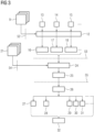
- Fig. 2 shows a flow chart of the entire process for collecting measurement data of an object under investigation 2 and Fig.3 shows the data structures and algorithms used. The devices by which the corresponding steps are implemented are shown in Fig.1 shown.
- reference data sets 9 are initially provided, each of which relates to a reference examination object 8.
- the reference data sets should make it possible in the later course of the method to determine an excitation distribution in the reference examination object and an energy input in at least one reference area of the examination object for a given control sequence.
- the reference data sets can describe a detailed electrodynamic model of the respective reference examination object. However, it can also be sufficient to use field distribution maps, in particular B 0 - and B 1 maps of the respective reference examination object as a reference data set and to use this data to modify, for example, a given electrodynamic model.
- the reference data sets can be recorded, for example, by the same magnetic resonance device 1 by examining the respective reference examination object 8 instead of the examination object 2.
- the reference data sets 9 are processed by an optimization process 12, which will be described in detail later with reference to Fig.4 will be explained. It is important here that the control sequences 16, 17, 18 determined by the optimization method 12 differ with respect to an optimization parameter 13, 14, 15 used in determining the respective control sequence 16, 17, 18.
- the optimization is carried out in particular with respect to a deviation measure that relates to a deviation of an excitation distribution presumably achieved in the reference examination object 8 within the scope of the respective control sequence 16, 17, 18 from a target excitation distribution, and with respect to an energy input into a reference area of the reference examination objects 8.
- the optimization parameter can specify which of these variables is the focus within the scope of the optimization.
- Step S2 or the Fig.3 The data processing shown between the dashed lines 52 and 53 can be carried out on an optimization device 11 as a preparatory calculation, which is carried out once by the manufacturer, for example.
- step S3 field distribution maps 21 are recorded with respect to the object under investigation 2.
- B 0 and B 1 maps are recorded.
- a B 1 map comprising phase information can be determined, in particular based on known transmission signals of the individual high-frequency transmission channels 5 and the reception signals received via the various antennas.
- the various control sequences 16, 17, 18 determined in step S2 by the optimization device 11 and the field distribution maps 21 determined by the magnetic resonance device 1 in step S3 are, in the example according to Fig.1 via the network 10, to a provision device 19.
- the provision device 19 is a separate device in the example. However, it could also be integrated into the magnetic resonance device 1 or into the optimization device 11.
- the provision device 19 is a data processing device 20 with a processor 23 and a memory 22.
- a computer program can be loaded into the memory 22 that implements the computer-implemented method explained below for providing a control sequence to be used.
- step S4 the computer-implemented method 24 selects one of the various control sequences 16, 17, 18 as the control sequence 25 to be used depending on the field distribution maps 21 and provides this, in the example via the network 10, to the control device 3 of the magnetic resonance device 1.
- a preliminary control sequence is first selected for which an energy input into the object under investigation 2 or into at least one area of the object under investigation 2 is predicted. If it is determined that this expected energy input is too large, for example above a limit value or a tolerance interval , another of the various control sequences is selected and this check is repeated. Even if the energy input is too small, another of the provisional control sequences can be selected, since an attempt can be made to improve the quality of the measurement data acquisition by using a higher but still permissible energy input.
- step S4 i.e. the area in Fig.3 between lines 53, 54 and 55, can be carried out as a separate process independently of the further steps on a separate facility, in the example on the provision facility 19, for example by a service provider or the manufacturer of the magnetic resonance imaging device 1.
- step S5 the method 26 for acquiring measurement data of an examination object 2 is used to control the gradient coils 6, 7 and the antenna arrangement 4 by the control device 3 according to the previously determined control sequence 25 to be used.
- the control information 27 relates, for example, to the gradient coil 6, the control information 28 to the gradient coil 7 and the transmission signals, of which only the transmission signals 29, 30, 31 are shown by way of example, each relate to one of the high-frequency transmission channels 5.
- the measurement data 32 are acquired by playing out these control sequences 25.
- Fig.4 shows in detail one possibility of implementing the optimization method 12 carried out in step S2.
- the reference data sets 9 and a target excitation distribution 33 are used as input data to optimize free parameters 35 of a control sequence 34 to be optimized.
- Fig.4 Only one optimization is specified for one of the optimization parameters 47.
- the procedure described can then be repeated with modified optimization parameters 13, 14, 15, 47 or in parallel.
- the control sequence 34 can, for example, be specified in a time-discrete manner, whereby amplitudes and phases for the various high-frequency transmission channels 5 and gradient strengths for the gradient coils 6, 7 can be specified for each point in time.
- other parameterizations and trajectories are also possible.
- a simulation algorithm 36 determines a presumed excitation distribution 37 for each of the reference data sets 9, which would presumably result from playing out the control sequence 34 for the reference examination object 8 described by the respective reference data set 9. In addition, the simulation algorithm 36 determines a respective expected energy input 38, 39, 40 for several areas of the reference examination object 8 described by the respective reference data set 9.
- the energy inputs can, as is known in principle from the prior art, be determined using an electrodynamic simulation or also using field distribution maps.
- the area in which the highest energy input 38, 39, 40 is expected is selected as the reference area for each of the reference examination objects, and the corresponding energy input is selected as the individual energy input 41 for the corresponding reference examination object and thus the corresponding reference data set 9 and the correspondingly parameterized control sequence 34.
- An average value 42 of the individual energy inputs 41 is then formed.
- the excitation distributions 37 expected to be achieved in each case are compared with the target excitation distribution 33 by a comparison function 43 in order to determine a deviation measure 44 for each of the reference data sets 9.
- the target excitation distribution 33 and the excitation distribution 37 expected to be achieved can be subtracted from one another and, for example, the standard deviation for This difference image can be calculated as a deviation measure 44.
- An average deviation measure 45 can then be calculated for the deviation measures 44.
- the deviation measure 45 and an energy input measure 48 are to be minimized together by an optimization process.
- a cost function 46 is used, which is a weighted sum of the deviation measure 45 and the energy input measure 48, with the weighting factors being specified by the optimization parameter 47.
- the parameters 35 of the control sequence 34 are modified by a modification algorithm 49 and the process is repeated in order to iteratively optimize the parameters 35.
- Known optimization methods for example a gradient descent method, can be used for this purpose. The optimization can be repeated for a certain number of passes or until a convergence criterion is met, for example until a value of the cost function 46 no longer changes significantly in successive passes.
- the problem of optimizing the parameters 35 of the control sequence is usually a non-convex optimization problem.
- the procedure described can be carried out several times for each value of the optimization parameter 47, using different starting points, i.e. starting values of the parameters 35. The result that leads to the smallest value of the cost function 46 can then be used.
- a functional relationship 51 between a respective determined mean value 42 of the individual energy inputs 41 and the respective optimization parameter 13, 14, 47 used can be provided, for example by a regression algorithm 50. This can be used to select the control sequence to be used or the provisional or new provisional control sequences used in the determination, as will be explained in more detail later.
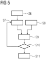
- Fig.5 shows a possible implementation of step S4 in Fig. 2 or the computer-implemented method 24 for providing a control sequence to be used.
- a maximum value for a permissible energy input into the object under investigation 2 is initially specified.
- an upper limit for the SED value can be specified.
- the limit value can be determined from the SAR limit values of the International Electronic Commission (IEC) and the sequence or protocol parameters.
- the SAR limit values are specified as limits for the radiated power. An average is calculated over ten seconds or six minutes. Based on these power limits, limits can also be specified for the energy radiated during the entire control sequence or during a section of the control sequence.
- step S7 one of the control sequences is selected depending on the specified limit value or interval. If the functional relationship 51 between the mean value 42 and the optimization parameter 13, 14, 15, 47 is known, an optimization parameter and thus also an associated control sequence can be selected directly, the average energy input for the reference examination objects being below the limit value or in the specified interval. If, however, the control sequences are directly assigned to mean values of the individual energy inputs, In this case, a control sequence can be selected immediately for which the average value of the individual energy inputs is smaller than the limit value or lies within the interval. In principle, it would also be possible to select the provisional control sequence in another way, for example randomly.
- step S8 the field distribution maps, in particular B 0 and B 1 maps, are provided for the object under investigation 2.
- the field distribution maps can be received from any source via an interface of a device implementing the method, for example read from a database. However, it is also possible to record the field distribution maps within the method itself.
- step S9 an energy input into a selected area of the object under investigation is predicted when using the preliminary control sequence specified in step S7.
- an energy input in several different areas of the object under investigation is first predicted.
- the virtual observation points already explained above are used here, i.e. an energy input is calculated in areas that are not necessarily connected, but for which a similar behavior is expected.
- the area in which the greatest energy input occurs can then be selected and this energy input can be used in step S10 to decide whether a usage condition is met.
- step S10 If the usage condition is met in step S10, which is particularly the case if the energy input is less than a limit value or is within a predetermined interval, the method is continued in step S11, in which the preliminary control sequence specified in step S7 is selected and provided as the control sequence to be used.
- step S7 a new provisional control sequence is selected.
- the new, provisional control sequence is selected randomly.
- consideration is given to the direction and extent in which the energy input determined in step S9 deviates from the limit value or from the interval. This can lead to a considerably faster determination of a control sequence in the desired energy input interval or below the limit value.
- the functional relationship 51 between the optimization parameters and the associated mean values 42 of the individual energy inputs 41 can be used, the provision of which with reference to Figure 4 explained. If, for example, it was determined that the predicted energy input for the preliminary control sequence is larger or smaller by a certain offset or factor than the average value of the individual energy inputs for this control sequence, the limit value or the interval limit can be corrected with this factor or offset in order to determine modified target values for the energy input.
- a target value for the optimization parameter can be determined from this modified target value for the energy input.
- a control sequence can therefore be selected whose optimization parameter is as close as possible to this target optimization parameter.
- the control sequence to be used can be determined within a few iterations, even when using a large number of different control sequences, for example with a few 10 or 100 control sequences.
Landscapes
- Physics & Mathematics (AREA)
- Condensed Matter Physics & Semiconductors (AREA)
- General Physics & Mathematics (AREA)
- Engineering & Computer Science (AREA)
- Signal Processing (AREA)
- High Energy & Nuclear Physics (AREA)
- Health & Medical Sciences (AREA)
- General Health & Medical Sciences (AREA)
- Nuclear Medicine, Radiotherapy & Molecular Imaging (AREA)
- Radiology & Medical Imaging (AREA)
- Magnetic Resonance Imaging Apparatus (AREA)
Claims (12)
- Procédé mis en oeuvre par ordinateur pour disposer d'une séquence (25) de commande à utiliser, qui, pour une saisie de données (32) de mesure d'un objet (2) en examen par un dispositif (1) de résonnance magnétique, prescrit, pour au moins un canal (5) d'émission en haute fréquence d'un agencement (4) d'antennes du dispositif (1) de résonnance magnétique, des signaux (29 - 31) d'émission respectifs à envoyer, comprenant les stades :- on se procure diverses séquences (16 - 18, 34) de commande, qui sont respectivement le résultat d'un procédé (12) d'optimisation et qui se distinguent en ce qui concerne la valeur d'un paramètre (13 - 15, 47) d'optimisation pris en compte dans le cadre du procédé d'optimisation (S2),- on se procure plusieurs cartes (21) de répartition du champ détectées sur l'objet (2) en examen par le ou par un autre dispositif (1) de résonnance magnétique (S3),- on choisit la séquence (25) de commande à utiliser parmi les diverses séquences (16 - 18, 34) de commande en fonction des cartes (21) de répartition du champ et on met à disposition la séquence (25) de commande à utiliser (S4), caractérisé en ce que les diverses séquences (16 - 18, 34) de commande sont des résultats d'un procédé (12) d'optimisation, dans le cadre duquel on minimise une fonction (46) de coût, qui est une somme pondérée de- une mesure (48) d'apport d'énergie, qui concerne un apport d'énergie escompté dans une partie de référence d'au moins un objet (8) de référence en examen décrit par un ensemble (9) respectif de données de référence, lors de l'utilisation d'une séquence (16 - 18, 34) de commande à optimiser, et- une mesure (45) d'écart, qui concerne un écart d'une répartition (37) d'excitation, obtenue probablement dans l'objet (8) de référence en examen dans le cadre de la séquence (34) de commande, à une répartition (33) d'excitation de consigne,dans lequel on prescrit la pondération relative de la mesure (48) d'apport d'énergie et de la mesure (45) d'écart par le paramètre (47) d'optimisation,en ce que l'on choisit, à partir des diverses séquences (16 - 18, 34) de commande, une séquence (16 - 18, 34) de commande provisoire et on prévoit, en fonction des cartes (21) de répartition du champ et de la séquence (16 - 18, 34) de commande provisoire, un apport d'énergie dans une partie sélectionnée de l'objet (2) en examen lors d'une utilisation de la séquence (16 - 18) de commande provisoire pour la saisie des données (32) de mesure,i) dans lequel on choisit la séquence de commande provisoire comme la séquence (25) de commande à utiliser, si l'apport d'énergie prévu est dans un intervalle donné à l'avance ou, si l'apport d'énergie prévu est en dehors d'un intervalle donné à l'avance, on choisit une nouvelle séquence (16 - 18, 34) de commande provisoire à partir des diverses séquences (16 - 18, 34) de commande et on répète le stade i) jusqu'à ce que l'apport d'énergie prévu soit dans l'intervalle donné à l'avance.
- Procédé mis en oeuvre par ordinateur suivant la revendication 1, caractérisé en ce que la mise à disposition de plusieurs cartes (21) de répartition du champ détectées par le un autre dispositif (1) de résonnance magnétique sur l'objet (2) en examen comprend une mise à disposition d'au moins d'une carte B0 et/ou d'au moins une carte Bi.
- Procédé mis en oeuvre par ordinateur suivant l'une des revendications précédentes, caractérisé en ce que l'on détermine, pour plusieurs parties de l'objet en examen, un apport d'énergie prévu respectif, dans lequel on choisit chacune des parties pour laquelle l'apport d'énergie prévu est le plus grand, dans lequel on choisit la séquence de commande à utiliser ou la nouvelle séquence de commande provisoire en fonction de l'apport d'énergie prévu dans cette partie choisie.
- Procédé mis en oeuvre par ordinateur suivant l'une des revendications précédentes, caractérisé en ce que, dans le procédé (12) d'optimisation, on prend en compte plusieurs objets (8) de référence en examen,
dans lequel, pour chacun des objets (8) de référence en examen et chacune des diverses séquences (16 - 18, 34) de commande, on détermine un apport (41) d'énergie propre, qui concerne un apport d'énergie escompté dans la partie de référence de cet objet (8) de référence en examen, lors de l'utilisation de cette séquence (16 - 18, 34) de commande, dans lequel, pour chacune des séquences (16 - 18, 34) de commande différentes, on détermine une valeur (42) moyenne des apports (41) d'énergie propre et on l'affecte soi-même à la séquence (16 - 18, 34) de commande ou au paramètre (47) d'optimisation utilisé pour la détermination de la séquence (16- 18, 34) de commande respective. - Procédé mis en oeuvre par ordinateur suivant la revendication 4, caractérisé en ce que, pour la séquence (16 - 18, 34) de commande respective, on détermine, pour plusieurs parties de l'objet (8) de référence en examen respectif, un apport (38 - 40) d'énergie escompté respectif,
dans lequel on choisit, comme apport (41) d'énergie propre, pour cette séquence (16 - 18, 34) de commande et cet objet (8) de référence en examen, le plus grand de ces apports (38 - 40) d'énergie escomptés. - Procédé mis en oeuvre par ordinateur suivant la revendication 4 ou 5, caractérisé en ce que, en fonction des valeurs (42) moyennes, affectées aux paramètres (47) d'optimisation respectifs, des apports (41) d'énergie propres, on détermine une relation (51) fonctionnelle entre les paramètres (47) d'optimisation et les valeurs (42) moyennes à affecter, dans lequel on choisit la séquence (25) de commande à utiliser et/ou la séquence (16 - 18, 34) provisoire de commande et/ou la nouvelle séquence provisoire de commande, en fonction de cette relation (51) fonctionnelle.
- Procédé mis en oeuvre par ordinateur suivant l'une des revendications précédentes, caractérisé en ce que les diverses séquences (16 - 18, 34) de commande comprennent en outre respectivement des informations (27, 28) de commande pour la commande d'au moins une bobine (6, 7) de gradient pour disposer d'un champ de gradient.
- Procédé de saisie de données de mesure d'un objet (2) en examen, en particulier pour l'imagerie médicale, par un dispositif (1) de résonnance magnétique,
caractérisé en ce que, par un agencement (4) d'antennes du dispositif (1) de résonnance magnétique, on envoie, dans le cadre de la saisie de données de mesure, par au moins un canal (5) d'émission en haute fréquence des signaux (29 - 31) d'émission, qui sont prescrits par une séquence (25) de commande, que l'on choisit par un procédé suivant l'une des revendications précédentes. - Procédé suivant la revendication 8, caractérisé en ce que l'on détecte des cartes (21) de répartition du champ par le dispositif (1) de résonnance magnétique.
- Dispositif de mise à disposition et/ou de résonnance magnétique, caractérisé en ce qu'il est agencé pour effectuer le procédé mis en oeuvre par ordinateur suivant l'une des revendications 1 à 7 et/ou pour effectuer le procédé suivant la revendication 8 ou 9.
- Programme d'ordinateur pour un dispositif de traitement de données ayant des instructions de programme qui, lorsqu'elles sont effectuées sur un dispositif (20) de traitement de données, exécutent un procédé mis en oeuvre par ordinateur suivant l'une des revendications 1 à 7 et/ou des instructions comprenant un programme d'ordinateur pour un dispositif de résonnance magnétique, qui font que le dispositif de résonnance magnétique exécute les stades du procédé suivant la revendication 8 ou 9.
- Support de données, déchiffrable par ordinateur, comprenant un programme d'ordinateur suivant la revendication 11.
Priority Applications (2)
| Application Number | Priority Date | Filing Date | Title |
|---|---|---|---|
| EP19202976.7A EP3809151B1 (fr) | 2019-10-14 | 2019-10-14 | Procédé mis en oeuvre par ordinateur permettant de fournir une séquence de commande et procédé de détection des données de mesure à l'aide d'un dispositif de résonance magnétique |
| US17/068,420 US11428767B2 (en) | 2019-10-14 | 2020-10-12 | Computer-implemented method for providing an actuation sequence and method for acquiring measurement data by a magnetic resonance device |
Applications Claiming Priority (1)
| Application Number | Priority Date | Filing Date | Title |
|---|---|---|---|
| EP19202976.7A EP3809151B1 (fr) | 2019-10-14 | 2019-10-14 | Procédé mis en oeuvre par ordinateur permettant de fournir une séquence de commande et procédé de détection des données de mesure à l'aide d'un dispositif de résonance magnétique |
Publications (3)
| Publication Number | Publication Date |
|---|---|
| EP3809151A1 EP3809151A1 (fr) | 2021-04-21 |
| EP3809151C0 EP3809151C0 (fr) | 2024-09-04 |
| EP3809151B1 true EP3809151B1 (fr) | 2024-09-04 |
Family
ID=68280970
Family Applications (1)
| Application Number | Title | Priority Date | Filing Date |
|---|---|---|---|
| EP19202976.7A Active EP3809151B1 (fr) | 2019-10-14 | 2019-10-14 | Procédé mis en oeuvre par ordinateur permettant de fournir une séquence de commande et procédé de détection des données de mesure à l'aide d'un dispositif de résonance magnétique |
Country Status (2)
| Country | Link |
|---|---|
| US (1) | US11428767B2 (fr) |
| EP (1) | EP3809151B1 (fr) |
Families Citing this family (5)
| Publication number | Priority date | Publication date | Assignee | Title |
|---|---|---|---|---|
| DE102020211727B3 (de) * | 2020-09-18 | 2021-11-04 | Siemens Healthcare Gmbh | Performance-Optimiertes Verfahren zur Bestimmung von gültigen Parameterdatensätzen |
| DE102022201236A1 (de) | 2022-02-07 | 2023-08-10 | Siemens Healthcare Gmbh | Verfahren zur Anregung von Kernspins |
| US20230346247A1 (en) * | 2022-05-02 | 2023-11-02 | The General Hospital Corporation | System and method for magnetic resonance imaging using shaped radio frequency pulses |
| DE102023205665A1 (de) | 2023-06-16 | 2024-12-19 | Siemens Healthineers Ag | Computerimplementiertes Verfahren zur Bereitstellung einer zu nutzenden Ansteuersequenz, Verfahren zum Erfassen von Messdaten, Bereitstellungs- und/oder Aufnahmesystem, Computerprogramm und elektronisch lesbarer Datenträger |
| DE102023206073A1 (de) | 2023-06-28 | 2025-01-02 | Siemens Healthineers Ag | Computerimplementiertes Verfahren zur Bereitstellung einer zu nutzenden Ansteuersequenz, Verfahren zum Erfassen von Messdaten, Magnetresonanzeinrichtung, Computerprogramm und elektronisch lesbarer Datenträger |
Family Cites Families (5)
| Publication number | Priority date | Publication date | Assignee | Title |
|---|---|---|---|---|
| DE102007013422B4 (de) * | 2007-03-20 | 2010-05-06 | Siemens Ag | Verfahren zur Steuerung eines Magnetresonanzsystems und Magnetresonanzsystem |
| DE102013205785B4 (de) * | 2013-04-02 | 2014-10-09 | Siemens Aktiengesellschaft | Ermittlung einer Magnetresonanzsystem-Ansteuersequenz auf Basis einer reduzierten Anzahl an Feldverteilungskarten |
| WO2016143460A1 (fr) * | 2015-03-06 | 2016-09-15 | 株式会社日立製作所 | Appareil d'imagerie par résonance magnétique et procédé de réglage des paramètres de compensation rf |
| EP3153874A1 (fr) | 2015-10-06 | 2017-04-12 | Commissariat À L'Énergie Atomique Et Aux Énergies Alternatives | Procédé de conception de séquences d'impulsions d'imagerie par résonance magnétique à transmission parallèle et procédé permettant de réaliser une imagerie par résonance magnétique utilisant de telles séquences |
| US20180024215A1 (en) * | 2016-07-21 | 2018-01-25 | Yudong Zhu | Signal coding and structure modeling for imaging |
-
2019
- 2019-10-14 EP EP19202976.7A patent/EP3809151B1/fr active Active
-
2020
- 2020-10-12 US US17/068,420 patent/US11428767B2/en active Active
Also Published As
| Publication number | Publication date |
|---|---|
| US20210109178A1 (en) | 2021-04-15 |
| EP3809151A1 (fr) | 2021-04-21 |
| US11428767B2 (en) | 2022-08-30 |
| EP3809151C0 (fr) | 2024-09-04 |
Similar Documents
| Publication | Publication Date | Title |
|---|---|---|
| DE102010013672B4 (de) | Verfahren und Einrichtung zur Ermittlung einer Magnetresonanzsystem-Ansteuersequenz und Verfahren zum Betrieb eines Magnetresonanzsystems | |
| EP3299833B1 (fr) | Génération améliorée des séries chronologiques de points image d'un objet examiné au moyen de la technique de résonance magnétique | |
| DE102004002009B4 (de) | Verfahren zum Betrieb eines Magnetresonanzsystems, Magnetresonanzsystem und Computerprogrammprodukt | |
| EP3809151A1 (fr) | Procédé mis en oeuvre par ordinateur permettant de fournir une séquence de commande et procédé de détection des données de mesure à l'aide d'un dispositif de résonance magnétique | |
| DE102012203512B4 (de) | Ermittlung einer MR-Messsequenz mittels eines Gradienten-Optimierungsverfahrens | |
| DE102005061567B3 (de) | Verfahren, Vorrichtung und Computerprogrammprodukt zur Justage der Feldstärke von Hochfrequenzpulsen sowie ein Magnetresonanz-Messsystem dazu | |
| DE102010033329B4 (de) | Verfahren und Einrichtung zur Ermittlung einer Magnetresonanzsystem-Ansteuersequenz und Verfahren zum Betrieb eines Magnetresonanzsystems | |
| DE102010015066B4 (de) | Verfahren und Einrichtung zur Ermittlung einer Magnetresonanzsystem-Ansteuersequenz und Verfahren zum Betrieb eines Magnetresonanzsystems | |
| DE102008044827B3 (de) | Verfahren und Vorrichtung zum Erzeugen einer zeitrasterangepassten Messsequenz für einen Magnetresonanz-Scanner, die auf einem Zeitraster des Magnetresonanz-Scanners ausführbar ist | |
| DE10338075B4 (de) | Verfahren zur ortsaufgelösten Messung der B1-Feldverteilung bei MR-Messungen | |
| DE102011006151B4 (de) | Ermittlung einer hinsichtlich eines HF-Energieparameters optimierten HF-Pulslänge eines Magnetresonanzsystems | |
| DE102011089448A1 (de) | Brustspule und Verfahren zur Erzeugung von Magnetresonanzaufnahmen der Brust | |
| DE102004013422B4 (de) | Verfahren zur Homogenisierung eines B1-Felds, Magnetresonanzsystem und Computerprogrammprodukt | |
| DE102011083959A1 (de) | Verfahren zur Ansteuerung eines Magnetresonanzsystems | |
| DE102013205785A1 (de) | Ermittlung einer Magnetresonanzsystem-Ansteuersequenz auf Basis einer reduzierten Anzahl an Feldverteilungskarten | |
| DE10338074B4 (de) | Verfahren zur Kompensation von Kontrastinhomogenitäten in Magnetresonanzbildern sowie Magnetresonanz-Messsystem und Computerprogrammprodukt | |
| DE102012207132B3 (de) | Ansteuerung eines Magnetresonanzsystems unter Ermittlung von Sendeskalierungsfaktoren für eine vorgegebene Zielmagnetisierung | |
| DE102012205664B4 (de) | Verfahren und Steuervorrichtung zur Ansteuerung eines Magnetresonanzsystems | |
| DE102010015044A1 (de) | Verfahren und Einrichtung zur Ermittlung einer Magnetresonanzsystem-Ansteuersequenz und Verfahren zum Betrieb eines Magnetresonanzsystems | |
| DE102012215255B3 (de) | Ansteuerung eines Magnetresonanzsystems unter Berücksichtigung aktueller komponentenbedingter B1-Feld-Maximalwerte | |
| DE102010063565B4 (de) | Verfahren und Einrichtung zur Ermittlung einer Magnetresonanzsystem-Ansteuersequenz | |
| DE102014201944B4 (de) | HF-Puls-Justage-Verfahren und HF-Puls-Justage-Einrichtung | |
| DE102011006149B4 (de) | Ermittlung einer Magnetresonanzsystem-Ansteuersequenz unter Optimierung der Sendebandbreite | |
| DE112012004208T5 (de) | Magnetresonanzabbildungsvorrichtung und Messverfahren für die Verteilung eines eingestrahlten Magnetfelds | |
| DE102012217770B3 (de) | Ermittlung einer der kürzesten Gesamtaufnahmezeit entsprechenden Gradientenstärke bei der MR-Bildgebung |
Legal Events
| Date | Code | Title | Description |
|---|---|---|---|
| PUAI | Public reference made under article 153(3) epc to a published international application that has entered the european phase |
Free format text: ORIGINAL CODE: 0009012 |
|
| STAA | Information on the status of an ep patent application or granted ep patent |
Free format text: STATUS: THE APPLICATION HAS BEEN PUBLISHED |
|
| AK | Designated contracting states |
Kind code of ref document: A1 Designated state(s): AL AT BE BG CH CY CZ DE DK EE ES FI FR GB GR HR HU IE IS IT LI LT LU LV MC MK MT NL NO PL PT RO RS SE SI SK SM TR |
|
| AX | Request for extension of the european patent |
Extension state: BA ME |
|
| RAP1 | Party data changed (applicant data changed or rights of an application transferred) |
Owner name: SIEMENS HEALTHCARE GMBH |
|
| STAA | Information on the status of an ep patent application or granted ep patent |
Free format text: STATUS: REQUEST FOR EXAMINATION WAS MADE |
|
| 17P | Request for examination filed |
Effective date: 20211005 |
|
| RBV | Designated contracting states (corrected) |
Designated state(s): AL AT BE BG CH CY CZ DE DK EE ES FI FR GB GR HR HU IE IS IT LI LT LU LV MC MK MT NL NO PL PT RO RS SE SI SK SM TR |
|
| RAP1 | Party data changed (applicant data changed or rights of an application transferred) |
Owner name: SIEMENS HEALTHINEERS AG |
|
| GRAP | Despatch of communication of intention to grant a patent |
Free format text: ORIGINAL CODE: EPIDOSNIGR1 |
|
| STAA | Information on the status of an ep patent application or granted ep patent |
Free format text: STATUS: GRANT OF PATENT IS INTENDED |
|
| INTG | Intention to grant announced |
Effective date: 20240405 |
|
| GRAS | Grant fee paid |
Free format text: ORIGINAL CODE: EPIDOSNIGR3 |
|
| GRAA | (expected) grant |
Free format text: ORIGINAL CODE: 0009210 |
|
| STAA | Information on the status of an ep patent application or granted ep patent |
Free format text: STATUS: THE PATENT HAS BEEN GRANTED |
|
| AK | Designated contracting states |
Kind code of ref document: B1 Designated state(s): AL AT BE BG CH CY CZ DE DK EE ES FI FR GB GR HR HU IE IS IT LI LT LU LV MC MK MT NL NO PL PT RO RS SE SI SK SM TR |
|
| REG | Reference to a national code |
Ref country code: GB Ref legal event code: FG4D Free format text: NOT ENGLISH |
|
| REG | Reference to a national code |
Ref country code: CH Ref legal event code: EP |
|
| REG | Reference to a national code |
Ref country code: IE Ref legal event code: FG4D Free format text: LANGUAGE OF EP DOCUMENT: GERMAN |
|
| REG | Reference to a national code |
Ref country code: DE Ref legal event code: R096 Ref document number: 502019012032 Country of ref document: DE |
|
| U01 | Request for unitary effect filed |
Effective date: 20240904 |
|
| U07 | Unitary effect registered |
Designated state(s): AT BE BG DE DK EE FI FR IT LT LU LV MT NL PT RO SE SI Effective date: 20240916 |
|
| U20 | Renewal fee for the european patent with unitary effect paid |
Year of fee payment: 6 Effective date: 20241018 |
|
| PG25 | Lapsed in a contracting state [announced via postgrant information from national office to epo] |
Ref country code: NO Free format text: LAPSE BECAUSE OF FAILURE TO SUBMIT A TRANSLATION OF THE DESCRIPTION OR TO PAY THE FEE WITHIN THE PRESCRIBED TIME-LIMIT Effective date: 20241204 |
|
| PG25 | Lapsed in a contracting state [announced via postgrant information from national office to epo] |
Ref country code: PL Free format text: LAPSE BECAUSE OF FAILURE TO SUBMIT A TRANSLATION OF THE DESCRIPTION OR TO PAY THE FEE WITHIN THE PRESCRIBED TIME-LIMIT Effective date: 20240904 Ref country code: GR Free format text: LAPSE BECAUSE OF FAILURE TO SUBMIT A TRANSLATION OF THE DESCRIPTION OR TO PAY THE FEE WITHIN THE PRESCRIBED TIME-LIMIT Effective date: 20241205 |
|
| PG25 | Lapsed in a contracting state [announced via postgrant information from national office to epo] |
Ref country code: HR Free format text: LAPSE BECAUSE OF FAILURE TO SUBMIT A TRANSLATION OF THE DESCRIPTION OR TO PAY THE FEE WITHIN THE PRESCRIBED TIME-LIMIT Effective date: 20240904 |
|
| PG25 | Lapsed in a contracting state [announced via postgrant information from national office to epo] |
Ref country code: ES Free format text: LAPSE BECAUSE OF FAILURE TO SUBMIT A TRANSLATION OF THE DESCRIPTION OR TO PAY THE FEE WITHIN THE PRESCRIBED TIME-LIMIT Effective date: 20240904 Ref country code: RS Free format text: LAPSE BECAUSE OF FAILURE TO SUBMIT A TRANSLATION OF THE DESCRIPTION OR TO PAY THE FEE WITHIN THE PRESCRIBED TIME-LIMIT Effective date: 20241204 |
|
| PG25 | Lapsed in a contracting state [announced via postgrant information from national office to epo] |
Ref country code: RS Free format text: LAPSE BECAUSE OF FAILURE TO SUBMIT A TRANSLATION OF THE DESCRIPTION OR TO PAY THE FEE WITHIN THE PRESCRIBED TIME-LIMIT Effective date: 20241204 Ref country code: PL Free format text: LAPSE BECAUSE OF FAILURE TO SUBMIT A TRANSLATION OF THE DESCRIPTION OR TO PAY THE FEE WITHIN THE PRESCRIBED TIME-LIMIT Effective date: 20240904 Ref country code: NO Free format text: LAPSE BECAUSE OF FAILURE TO SUBMIT A TRANSLATION OF THE DESCRIPTION OR TO PAY THE FEE WITHIN THE PRESCRIBED TIME-LIMIT Effective date: 20241204 Ref country code: HR Free format text: LAPSE BECAUSE OF FAILURE TO SUBMIT A TRANSLATION OF THE DESCRIPTION OR TO PAY THE FEE WITHIN THE PRESCRIBED TIME-LIMIT Effective date: 20240904 Ref country code: GR Free format text: LAPSE BECAUSE OF FAILURE TO SUBMIT A TRANSLATION OF THE DESCRIPTION OR TO PAY THE FEE WITHIN THE PRESCRIBED TIME-LIMIT Effective date: 20241205 Ref country code: ES Free format text: LAPSE BECAUSE OF FAILURE TO SUBMIT A TRANSLATION OF THE DESCRIPTION OR TO PAY THE FEE WITHIN THE PRESCRIBED TIME-LIMIT Effective date: 20240904 |
|
| PG25 | Lapsed in a contracting state [announced via postgrant information from national office to epo] |
Ref country code: IS Free format text: LAPSE BECAUSE OF FAILURE TO SUBMIT A TRANSLATION OF THE DESCRIPTION OR TO PAY THE FEE WITHIN THE PRESCRIBED TIME-LIMIT Effective date: 20250104 |
|
| PG25 | Lapsed in a contracting state [announced via postgrant information from national office to epo] |
Ref country code: SM Free format text: LAPSE BECAUSE OF FAILURE TO SUBMIT A TRANSLATION OF THE DESCRIPTION OR TO PAY THE FEE WITHIN THE PRESCRIBED TIME-LIMIT Effective date: 20240904 |
|
| PG25 | Lapsed in a contracting state [announced via postgrant information from national office to epo] |
Ref country code: CZ Free format text: LAPSE BECAUSE OF FAILURE TO SUBMIT A TRANSLATION OF THE DESCRIPTION OR TO PAY THE FEE WITHIN THE PRESCRIBED TIME-LIMIT Effective date: 20240904 |
|
| PG25 | Lapsed in a contracting state [announced via postgrant information from national office to epo] |
Ref country code: SK Free format text: LAPSE BECAUSE OF FAILURE TO SUBMIT A TRANSLATION OF THE DESCRIPTION OR TO PAY THE FEE WITHIN THE PRESCRIBED TIME-LIMIT Effective date: 20240904 |
|
| REG | Reference to a national code |
Ref country code: CH Ref legal event code: PL |
|
| PG25 | Lapsed in a contracting state [announced via postgrant information from national office to epo] |
Ref country code: MC Free format text: LAPSE BECAUSE OF FAILURE TO SUBMIT A TRANSLATION OF THE DESCRIPTION OR TO PAY THE FEE WITHIN THE PRESCRIBED TIME-LIMIT Effective date: 20240904 |
|
| PLBE | No opposition filed within time limit |
Free format text: ORIGINAL CODE: 0009261 |
|
| STAA | Information on the status of an ep patent application or granted ep patent |
Free format text: STATUS: NO OPPOSITION FILED WITHIN TIME LIMIT |
|
| PG25 | Lapsed in a contracting state [announced via postgrant information from national office to epo] |
Ref country code: CH Free format text: LAPSE BECAUSE OF NON-PAYMENT OF DUE FEES Effective date: 20241031 |
|
| 26N | No opposition filed |
Effective date: 20250605 |
|
| PG25 | Lapsed in a contracting state [announced via postgrant information from national office to epo] |
Ref country code: IE Free format text: LAPSE BECAUSE OF NON-PAYMENT OF DUE FEES Effective date: 20241014 |
|
| U20 | Renewal fee for the european patent with unitary effect paid |
Year of fee payment: 7 Effective date: 20251020 |
|
| PGFP | Annual fee paid to national office [announced via postgrant information from national office to epo] |
Ref country code: GB Payment date: 20251111 Year of fee payment: 7 |
|
| PG25 | Lapsed in a contracting state [announced via postgrant information from national office to epo] |
Ref country code: CY Free format text: LAPSE BECAUSE OF FAILURE TO SUBMIT A TRANSLATION OF THE DESCRIPTION OR TO PAY THE FEE WITHIN THE PRESCRIBED TIME-LIMIT; INVALID AB INITIO Effective date: 20191014 |
|
| PG25 | Lapsed in a contracting state [announced via postgrant information from national office to epo] |
Ref country code: HU Free format text: LAPSE BECAUSE OF FAILURE TO SUBMIT A TRANSLATION OF THE DESCRIPTION OR TO PAY THE FEE WITHIN THE PRESCRIBED TIME-LIMIT; INVALID AB INITIO Effective date: 20191014 |