EP3809162B1 - Dispositif de réception par gnss et procédé de réception par gnss - Google Patents
Dispositif de réception par gnss et procédé de réception par gnss Download PDFInfo
- Publication number
- EP3809162B1 EP3809162B1 EP19819827.7A EP19819827A EP3809162B1 EP 3809162 B1 EP3809162 B1 EP 3809162B1 EP 19819827 A EP19819827 A EP 19819827A EP 3809162 B1 EP3809162 B1 EP 3809162B1
- Authority
- EP
- European Patent Office
- Prior art keywords
- gnss
- gnss signal
- signal
- antennas
- satellite
- Prior art date
- Legal status (The legal status is an assumption and is not a legal conclusion. Google has not performed a legal analysis and makes no representation as to the accuracy of the status listed.)
- Active
Links
Images



Classifications
-
- G—PHYSICS
- G01—MEASURING; TESTING
- G01S—RADIO DIRECTION-FINDING; RADIO NAVIGATION; DETERMINING DISTANCE OR VELOCITY BY USE OF RADIO WAVES; LOCATING OR PRESENCE-DETECTING BY USE OF THE REFLECTION OR RERADIATION OF RADIO WAVES; ANALOGOUS ARRANGEMENTS USING OTHER WAVES
- G01S19/00—Satellite radio beacon positioning systems; Determining position, velocity or attitude using signals transmitted by such systems
- G01S19/01—Satellite radio beacon positioning systems transmitting time-stamped messages, e.g. GPS [Global Positioning System], GLONASS [Global Orbiting Navigation Satellite System] or GALILEO
- G01S19/13—Receivers
- G01S19/22—Multipath-related issues
-
- G—PHYSICS
- G01—MEASURING; TESTING
- G01S—RADIO DIRECTION-FINDING; RADIO NAVIGATION; DETERMINING DISTANCE OR VELOCITY BY USE OF RADIO WAVES; LOCATING OR PRESENCE-DETECTING BY USE OF THE REFLECTION OR RERADIATION OF RADIO WAVES; ANALOGOUS ARRANGEMENTS USING OTHER WAVES
- G01S3/00—Direction-finders for determining the direction from which infrasonic, sonic, ultrasonic or electromagnetic waves, or particle emission, not having a directional significance, are being received
- G01S3/02—Direction-finders for determining the direction from which infrasonic, sonic, ultrasonic or electromagnetic waves, or particle emission, not having a directional significance, are being received using radio waves
- G01S3/14—Systems for determining direction or deviation from predetermined direction
- G01S3/46—Systems for determining direction or deviation from predetermined direction using antennas spaced apart and measuring phase or time difference between signals therefrom, i.e. path-difference systems
- G01S3/50—Systems for determining direction or deviation from predetermined direction using antennas spaced apart and measuring phase or time difference between signals therefrom, i.e. path-difference systems the waves arriving at the antennas being pulse modulated and the time difference of their arrival being measured
-
- G—PHYSICS
- G01—MEASURING; TESTING
- G01S—RADIO DIRECTION-FINDING; RADIO NAVIGATION; DETERMINING DISTANCE OR VELOCITY BY USE OF RADIO WAVES; LOCATING OR PRESENCE-DETECTING BY USE OF THE REFLECTION OR RERADIATION OF RADIO WAVES; ANALOGOUS ARRANGEMENTS USING OTHER WAVES
- G01S19/00—Satellite radio beacon positioning systems; Determining position, velocity or attitude using signals transmitted by such systems
- G01S19/01—Satellite radio beacon positioning systems transmitting time-stamped messages, e.g. GPS [Global Positioning System], GLONASS [Global Orbiting Navigation Satellite System] or GALILEO
- G01S19/13—Receivers
- G01S19/21—Interference related issues ; Issues related to cross-correlation, spoofing or other methods of denial of service
- G01S19/215—Interference related issues ; Issues related to cross-correlation, spoofing or other methods of denial of service issues related to spoofing
Definitions
- the present invention relates to a Global Navigation Satellite System (GNSS) receiver and a GNSS receiving method.
- GNSS Global Navigation Satellite System
- JP 2005 077376 A discloses an apparatus for receiving a signal transmitted from a transmission source by a reference receiver and a calibration target receiver, respectively, and processing the received signal based on carrier phase information of the received signal by the reception calculates a single difference between the receivers, which is a difference in the carrier phase information of the received signal obtained by observation of the reference receiver and the calibration target receiver, and the reception point of the reference receiver and the calibration target receiver and the transmission. Based on the position of the source, a single phase difference between the receivers in the carrier phase between the reference receiver and the calibration target receiver is obtained, and the single difference between the receivers and the observed single difference between the receivers are calculated.
- the determination module determines whether the GNSS signal received by the antenna is a direct GNSS signal based on a direct wave from the satellite or a non-line-of-sight (NLOS) GNSS signal by comparing the direction in which the satellite is viewed from the antenna with the arrival direction estimated by the estimation module.
- NLOS non-line-of-sight
- the GNSS receiver includes at least two antennas, an estimation module, and a determination module.
- the estimation module obtains the angular spectrum of the intensity of the GNSS signal with respect to the estimation of the arrival direction of the GNSS signal on the basis of the difference in timing at which the GNSS signal is received by the plurality of antennas.
- the determination module determines, based on the angular spectrum obtained by the estimation module, whether the GNSS signal received by the antenna is a direct GNSS signal based on a direct wave from a satellite or an NLOS GNSS signal.
- the received signal is a GNSS signal based on a direct wave from the satellite or a NLOS GNSS signal by determining the angular spectrum with respect to the estimation of the arrival direction of the GNSS signal.
- the angular spectrum when a direct GNSS signal is received shows a distribution with a single peak in a certain direction. This property can be used to properly distinguish between direct GNSS signals and NLOS GNSS signals.
- the direction of arrival of the GNSS signal can be estimated by simple processing.
- the estimation module can also estimate the arrival direction of the GNSS signal from the phase difference of the carrier wave of the GNSS signal received by the plurality of antennas.
- the antennas are fixedly provided so that their positions do not fluctuate with respect to the ground.
- the arrival direction of the GNSS signal can be stably estimated.
- the GNSS receiver preferably includes at least three antennas.
- the arrival direction of the GNSS signal can be well estimated.
- the timing at which each antenna receives the GNSS signal can be expressed by using the common clock. Therefore, the arrival direction of the GNSS signal can be estimated by accurately and easily determining the difference in the reception timing of the GNSS signal.
- the GNSS receiving apparatus preferably includes an NLOS GNSS signal removal module for removing the NLOS GNSS signal from the received GNSS signal based on the determination result of the determination module.
- the GNSS receiving apparatus includes a notification module for notifying the reception of the NLOS GNSS signal based on the determination result of the determination module.
- the GNSS receiver includes at least two antennas, an angular spectrum acquisition module, and a display data generation module.
- the angular spectrum acquisition module obtains the angular spectrum of the intensity of the GNSS signal on the basis of the difference in timing of receiving the GNSS signal by the plurality of antennas.
- the display data generation module generates data for displaying the angular spectrum.
- the user can concretely grasp the radio wave reception state of the GNSS signal.
- the GNSS receiver preferably has the following configuration. That is, the angular spectrum acquisition module obtains the angular spectrum of the intensity of the GNSS signal as a two-dimensional angular spectrum relating to the azimuth angle and the elevation angle.
- the display data generation module generates data for graphically displaying the angular spectrum in the celestial sphere.
- the angular spectrum can be visually and easily understood and displayed.
- the signal intensity in the angular spectrum to be displayed is preferably expressed by a color scale, a shade of a color or an equal intensity line.
- the GNSS receiver preferably has the following configuration. That is, the GNSS receiver is provided with a satellite direction acquisition module for acquiring the direction viewed from the antenna of the satellite corresponding to the GNSS signal received by the antenna based on the satellite orbit information.
- the display data generation module generates data for displaying the direction when the satellite is viewed from the antenna.
- the following GNSS receiving method is provided. That is, at least two antennas receive GNSS signals. A direction in which a satellite corresponding to the GNSS signal received by the antenna is viewed from the antenna is acquired based on satellite orbit information. The arrival direction of the GNSS signal is estimated on the basis of a difference in timing when the GNSS signal is received by a plurality of antennas. The direction in which the satellite is viewed from the antenna is compared with the estimated arrival direction of the GNSS signal to determine whether the GNSS signal received by the antenna is a direct GNSS signal based on a direct wave from the satellite or an NLOS GNSS signal.
- the following GNSS receiving method is provided. That is, at least two antennas receive GNSS signals.
- the angular spectrum of the intensity of the GNSS signal is obtained on the basis of the difference of the timing when the GNSS signal is received by the plurality of antennas. Based on the angular spectrum, it is determined whether the GNSS signal received by the antenna is a direct GNSS signal based on a direct wave from a satellite or an NLOS GNSS signal.
- the following GNSS receiving method is provided. That is, at least two antennas receive GNSS signals.
- the angular spectrum of the intensity of the GNSS signal is obtained on the basis of the difference of the timing when the GNSS signal is received by the plurality of antennas. Data for displaying the angular spectrum is generated.
- FIG. 1 is a block diagram showing an electrical configuration of a GNSS receiver 1 according to an embodiment of the present invention.
- FIG. 2 shows an example of the arrangement of the antennas 11 of the GNSS receiver 1.
- the GNSS receiver 1 outputs a Pulse Per Second (1PPS) signal accurately synchronized with the GNSS time as a timing pulse based on the received GNSS signal, and can be used, for example, in a communication base station or a broadcasting station.
- the GNSS receiver 1 determines whether the received GNSS signal is a direct GNSS signal or a Non-line-of-sight (NLOS) GNSS signal, and performs positioning calculation by excluding the NLOS GNSS signal to output a timing pulse signal with high accuracy.
- NLOS Non-line-of-sight
- a direct GNSS signal means a GNSS signal directly receiving a radio wave transmitted from a GNSS satellite.
- the antenna array may include six antennas 11 that are arranged so as to correspond to face center positions of 6 faces in a regular hexahedron.
- FIG.2 when a first satellite 101 existing in a region of a high elevation angle as viewed from the antenna array transmits a GNSS signal, the GNSS signal 111 is received by two antennas 11 on the upper and lower surfaces of a regular hexahedron, in the order of upper and lower with a time difference.
- the multipath GNSS signal 112 reflected from the GNSS signal after striking from a building or the like, will be described later.
- the determination module 53 can determine that the GNSS signal 111 is a direct GNSS signal and the GNSS signal 112 is an NLOS GNSS signal.
- the determination module 53 can determine that the GNSS signal received from such a transmitting device is an NLOS GNSS signal by comparing directions in exactly the same manner as described above.
- the decision process module 51 outputs the determination result of the determination module 53 to the filter module 61.
- the filter module 61 receives GNSS signals from the baseband processing module 41 of one reception module 44, and also receives a determination result from the decision process module 51.
- the filter module 61 selectively removesa signal determined as an NLOS GNSS signal by the determination module 53 from the GNSS signal input from the reception module 41.
- the GNSS signal generated after the filter processing becomes only the direct GNSS signal.
- the filter module 61 outputs the GNSS signal after the filter processing to the position calculation module 71.
- the timing pulse generation module 81 generates a pulse signal of 1 time per second (1 PPS signal) synchronized with the GNSS time based on the GNSS time inputted from the position calculation module 71.
- the timing pulse signal generated by the timing pulse generation module 81 is output from the GNSS receiver 1 and input to an external device such as a reference frequency generator.
- the GNSS receiver 1 determines whether a received GNSS signal is a direct GNSS signal or an NLOS GNSS signal, performs positioning calculation excluding an NLOS GNSS signal reducing positioning accuracy, and generates a timing pulse. Therefore, the effect of the multipath and the spoofing signal can be avoided, and the accurate timing pulse can be stably outputted.
- the reception timing of the GNSS signal is specified in the plurality of reception modules 41, and the plurality of reception modules 41 are supplied with a common clock signal from a single clock pulse generation module 31. Therefore, since the plurality of reception modules 41 can represent the reception timing with a common reference, the estimation module 52 can accurately and easily obtain the time difference of the reception timing.
- the GNSS receiving device 1 is not limited to the application for generating a timing pulse. For example, it can be suitably used not only for navigation using a positioning result outputted from the GNSS receiver 1 but also for various other purposes.
- the number and arrangement of the antennas 11 constituting the antenna array can be variously changed.
- the antenna 11 may be further disposed at a body center position of a regular hexahedron.
- an appropriate number of antennas can be arranged side by side so as to form a polygon in a horizontal plane.
- the antenna array described in FIG. 2 also satisfies this condition, but as the simplest antenna array satisfying this condition, a configuration in which three antennas 11 are arranged so as to form a triangle is conceivable.
- the antenna array may be composed of two antennas 11.
- the arrival direction of the GNSS signal cannot be estimated at a pin point, but the arrival direction should be a bus bar of a conical surface having the position of the antenna array as a vertex and a virtual straight line connecting the 2 antennas 11 as an axis.
- the angle formed by the bus of the conical surface with the imaginary straight line (axis) is equal to 90° minus the angle ⁇ described above.
- the estimation module 52 may estimate the arrival direction of the GNSS signal so as to narrow it to a certain range.
- the determination module 53 can be configured to determine that the GNSS signal is an NLOS GNSS signal when the direction in which the GNSS satellite corresponding to the GNSS signal is viewed from the antenna array is deviated from the conical surface by a predetermined distance or more.
- the estimation module 52 estimates that the direction of arrival of the GNSS signal is generally south.
- the determination module 53 determines that the GNSS signal is an NLOS GNSS signal.
- the GNSS receiver 1 estimates the arrival direction of the GNSS signal by using the reception time difference of the PRN code when the GNSS signal is received by the two antennas 11.
- the carrier wave phase difference of the GNSS signal can be used to estimate the arrival direction of the GNSS signal.
- the direction of arrival of the GNSS signal can be precisely estimated. Since, the phase is an angular representation of time, the carrier phase difference is a kind of difference in the reception timing of the GNSS signal.
- the GNSS receiver 1 includes at least two antennas 11, the baseband processing module 44, the estimation module 52, and the determination module 53.
- the baseband processing module 44 acquires the direction in which the satellite 101, 102 corresponding to the GNSS signal received by the antenna 11 is viewed from the antenna 11 based on the satellite orbit information.
- the estimation module 52 estimates the arrival direction of the GNSS signal 111, 112 and 113 on the basis of the difference ⁇ t between the timings at which the GNSS signal is received by the plurality of antennas 11..
- the determination module 53 compares the direction in which the satellite 101,102 is viewed from the antenna with the arrival direction estimated by the estimation module 52, and determines whether the GNSS signal (111,112,113) received by the antenna 11 is a direct GNSS signal based on a direct wave from the satellite (101,102) or an NLOS GNSS signal.
- the received GNSS signal is a direct GNSS signal or an NLOS GNSS signal based on a simple method for comparing the estimated arrival direction of the GNSS signal 111,112,113 with the direction of the satellite 101, 102 as viewed from the antenna 11.
- the estimation module 52 may be configured to determine the angular spectrum of the intensity of the GNSS signal based on the difference ⁇ t between the reception timings of the GNSS signal at the plurality of antennas 11.
- the angular spectrum can be calculated using known methods such as the minimum norm method, the linear prediction method, the Multiple Signal Classification (MUSIC) method, and the like.
- the angular spectrum may be obtained based on the difference in the timing of the PRN code included in the GNSS signal, or may be obtained from the phase difference of the carrier wave of the GNSS signal. However, it is preferable to use the phase difference of the carrier wave because a highly accurate angular spectrum can be obtained.
- determining the angular spectrum of the intensity of the GNSS signal is substantially the same as determining the distribution of correctness when a direction is assumed to be the arrival direction of the GNSS signal.
- the angular spectrum may be a one-dimensional spectrum relating to either the azimuth angle or the elevation angle, but preferably a two-dimensional spectrum relating to both.
- FIGS. 3A and 3B show examples of the angular spectrum determined by the estimation module 52 of FIG.1 .
- a two-dimensional angular spectrum is arranged on the inner surface of a virtual sphere (celestial sphere) centered on the antenna array, and the celestial sphere is looked up from the point of the antenna array.
- the angle from the center of the circle corresponds to the azimuth angle in the direction of arrival of the GNSS signal.
- the outermost circle corresponds to an elevation angle of 0° in the arrival direction, and the center of the circle corresponds to an elevation angle of 90° in the arrival direction.
- the signal intensity is represented by the spacing of the hatches.
- the narrow hatched areas indicate high signal strength
- wide hatched areas indicate low signal strength
- unhatched areas indicate substantially zero signal strength.
- the determination module 53 can determine the direct GNSS signal and the NLOS GNSS signal, for example, as follows. A plurality of the following four determination methods may be combined. Further, the determination method may be switched according to the accuracy required in the positioning operation or the like.
- the signal intensity corresponding to the direction of the satellite calculated by the baseband processing module 44 is obtained by using the angular spectrum, and if the signal intensity is not less than a predetermined intensity, the determination module 53 determines that the signal is a direct GNSS signal, and otherwise determines that the signal is an NLOS GNSS signal.
- the direction of the satellite calculated by the baseband processing module 44 is indicated by an X.
- the signal intensity at the position corresponding to the mark X is large, and in the case of FIG. 3B , the signal intensity at the position corresponding to the mark X is zero. Therefore, the determination module 53 determines that the GNSS signal of FIG. 3A is a direct GNSS signal, and determines that the GNSS signal of FIG. 3B is an NLOS GNSS signal.
- the direction corresponding to the peak of the signal intensity in the angular spectrum is determined, and this direction is compared with the direction of the satellite calculated by the baseband processing module 44, and if the difference in direction is within a predetermined range, the determination module 53 determines that the signal is a direct GNSS signal, and if not, it determines that the signal is an NLOS GNSS signal.
- the determination module 53 determines that the GNSS signal shown in FIG. 3B is an NLOS GNSS signal.
- the determination module 53 determines that the signal is an NLOS GNSS signal.
- the determination module 53 determines that the GNSS signal shown in FIG. 3B is an NLOS GNSS signal.
- the angle spectra of the GNSS signals representing a plurality of satellites are compared, and if they are similar to each other, the determination module 53 determines that they are NLOS GNSS signals. That is, when a malicious person transmits a spoofing signal in order to mislead the current position of the mobile body to a specific position, it is necessary to transmit the GNSS signal to the mobile body by spoofing a plurality of different satellites. On the other hand, since most of the facilities for transmitting the spoofing signal are one or a few, the spoofing signal is transmitted from a small number of places.
- the spoofing signal is a GNSS signal indicating a plurality of different satellites
- the angular spectra thereof tend to be similar to each other.
- the received GNSS signal is an NLOS GNSS signal (In particular, whether it is a spoofing signal or not).
- One countermeasure for spoofing signals is the need to locate the source of such signals.
- the antenna arrays are arranged at a distance from each other, and the arrival direction of the spoofing signals received in the respective antenna arrays is estimated, the position of the transmission source can be known by a known geometric calculation.
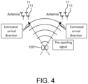
- FIG. 4 shows a conceptual diagram for obtaining the position of a GNSS spoofer 105, in accordance with an embodiment of the present disclosure.
- the GNSS spoofer 105 is hereinafter referred to as a spoofing attacker or a malicious transmitter 105, which is the transmission source of the spoofing signal, by using a plurality of antenna arrays.
- the estimation of the arrival direction of the spoofing signal can be realized, for example, by obtaining a direction corresponding to the peak of the angular spectrum calculated in each antenna array.
- the GNSS spoofer 105 exists at a point where a straight line extending in the opposite direction of the arrival direction of the spoofing signal intersects.
- the number of antenna arrays is preferably large in order to obtain the position of the transmission source with high accuracy.
- the estimation module 52 can be configured to obtain the angular spectrum of the intensity of the GNSS signal with respect to the estimation of the arrival direction of the GNSS signal, based on the difference in the timing at which the GNSS signal is received by the plurality of antennas 11.
- the determination module 53 determines whether the GNSS signal received by the antenna 11 is a direct GNSS signal or an NLOS GNSS signal on the basis of the angular spectrum determined by the estimation module 52.
- the received GNSS signal is a GNSS signal based on a direct wave from the satellite or not.
- the angular spectrum is not limited to the use of estimating the direction of arrival of the GNSS received signal, but may be calculated for the purpose of simply displaying the signal for monitoring, for example.
- FIG. 5 illustrates the GNSS receiver 1x, in accordance with another embodiment of the present disclosure.
- a decision process module 51 the filter module 61, the position calculation module 71, and the timing pulse generation module 81 are omitted.
- the GNSS receiver 1x includes an angular spectrum acquisition module 91 and a display data generation module 92.
- the satellite direction acquisition module 21, the angular spectrum acquisition module 91 and the display data generation module 92 may also be implemented as "processing circuitry" 99.
- the angular spectrum acquisition module 91 calculates and acquires the angular spectrum of the intensity of the GNSS signal for each satellite number (In other words, for each PRN code number) based on the phase difference of the carrier wave of the GNSS signal of each satellite obtained from the baseband processing module 44. Since, the operation of the angular spectrum acquisition module 91 is exactly the same as that of the estimation module 52 of FIG. 1 for calculating the angular spectrum, a detailed description thereof is omitted.
- the display data generation module 92 generates display data for displaying the angular spectrum obtained by the angular spectrum acquisition module 91 on a display device 3 connected to the GNSS receiver 1x.
- the display device 3 is configured as a liquid crystal display, for example, and can display various information.
- the satellite orbit information may not be acquired from the GNSS signal transmitted from the satellite.
- the GNSS receivers 1 and 1x may be configured to be connected to the Internet, and the reception module 41 may acquire satellite orbit information from GNSS assist data distributed through the Internet.
- the arrival directions of GNSS signals representing a plurality of different satellites are estimated by pinpoints, and when the difference in the angle of the estimated arrival directions is not more than a predetermined value.
- the determination module 53 determines that the GNSS signals are NLOS GNSS signals (spoofing signal).
- the GNSS receivers 1 and 1x may be integrally provided with the display device 3.
Landscapes
- Engineering & Computer Science (AREA)
- Radar, Positioning & Navigation (AREA)
- Remote Sensing (AREA)
- Physics & Mathematics (AREA)
- General Physics & Mathematics (AREA)
- Computer Networks & Wireless Communication (AREA)
- Position Fixing By Use Of Radio Waves (AREA)
Claims (14)
- Récepteur de système de positionnement par satellites, GNSS, (1, 1x) comprenant :au moins deux antennes (11) ;un module d'acquisition de direction de satellite (44) configuré pour acquérir, sur la base d'informations d'orbite de satellite, une direction vue à partir des au moins deux antennes (11), d'un satellite (101, 102) correspondant à un signal GNSS (111, 112, 113) reçu par les au moins deux antennes (11) ;un module d'estimation (52) configuré pour estimer une direction d'arrivée du signal GNSS (111, 112, 113) sur la base d'une différence des instants auxquels le signal GNSS (111, 112, 113) est reçu par les au moins deux antennes (11) ; etun module de détermination (53) configuré pour déterminer si le signal GNSS (111, 112, 113) reçu par les au moins deux antennes (11) est un signal GNSS direct sur la base d'une onde directe provenant du satellite (101, 102) ou d'un signal GNSS sans visibilité directe, NLOS, en comparant la direction dans laquelle le satellite (101, 102) est vu à partir des au moins deux antennes (11) avec la direction d'arrivée estimée par le module d'estimation (52), caractérisé en ce que :
le module de détermination (53) détermine que le signal GNSS est le signal GNSS NLOS lorsque les directions d'arrivée d'une pluralité de signaux GNSS (111, 112, 113) estimées par le module d'estimation (52) sont similaires les unes aux autres bien que la pluralité de signaux GNSS reçus par les au moins deux antennes (11) indiquent des satellites sources (101, 102) différents, dans lequel les directions d'arrivée sont similaires lorsque les angles des directions d'arrivée sont similaires. - Récepteur de système de positionnement par satellites, GNSS, (1, 1x) comprenant :au moins deux antennes (11) ;un module d'estimation (52) configuré pour estimer un spectre angulaire d'une intensité d'un signal GNSS (111, 112, 113) par rapport à une estimation d'une direction d'arrivée du signal GNSS (111, 112, 113) sur la base de la différence des instants auxquels le signal GNSS (111, 112, 113) est reçu par les au moins deux antennes (11) ; etun module de détermination (53) configuré pour déterminer si le signal GNSS (111, 112, 113) reçu par l'antenne (11) est un signal GNSS direct (111, 112, 113) sur la base d'une onde directe provenant d'un satellite ou d'un signal GNSS sans visibilité directe, NLOS, sur la base du spectre angulaire obtenu par le module d'estimation (52), caractérisé en ce que :
le module de détermination (53) détermine que le signal GNSS est le signal GNSS NLOS lorsque les directions d'arrivée d'une pluralité de signaux GNSS (111, 112, 113) estimées par le module d'estimation (52) sont similaires les unes aux autres bien que la pluralité de signaux GNSS reçus par les au moins deux antennes (11) indiquent des satellites sources (101, 102) différents, dans lequel les directions d'arrivée sont similaires lorsque les spectres d'angle estimés par le module d'estimation (52) sont similaires les uns aux autres. - Récepteur GNSS (1, 1x) selon la revendication 2, comprenant en outre :
un module d'acquisition de direction de satellite (44) configuré pour acquérir, sur la base d'informations d'orbite de satellite, une direction vue à partir de l'antenne d'un satellite (101, 102) correspondant au signal GNSS reçu par les au moins deux antennes (11), dans lequel :
le module de détermination (53) est configuré pour déterminer si le signal GNSS reçu par les au moins deux antennes (11) est le signal GNSS direct ou le signal GNSS NLOS en utilisant également une valeur d'intensité du signal GNSS correspondant à une direction vue à partir de l'antenne du satellite sur la base du spectre angulaire. - Récepteur GNSS (1, 1x) selon la revendication 2, comprenant en outre :un module d'acquisition de direction de satellite (44) configuré pour acquérir, sur la base d'informations d'orbite de satellite, une direction vue à partir de l'antenne d'un satellite (101, 102) correspondant au signal GNSS reçu par les au moins deux antennes (11), dans lequelle module de détermination (53) est configuré pour déterminer si le signal GNSS reçu par les au moins deux antennes (11) est le signal GNSS direct ou le signal GNSS NLOS en comparant la direction dans laquelle le satellite (101, 102) est vu à partir des au moins deux antennes (11) avec la direction correspondant au pic du spectre angulaire.
- Récepteur GNSS (1, 1x) selon l'une des revendications 2 à 4, dans lequel :
le module de détermination (53) détermine que le signal GNSS reçu par les au moins deux antennes est le signal GNSS NLOS lorsque le spectre angulaire présente une pluralité de pics. - Récepteur GNSS (1, 1x) selon l'une des revendications 1 à 5, dans lequel :
le récepteur GNSS est configuré pour, si un signal GNSS NLOS est déterminé par le module de détermination (53) comme étant présent, délivrer en sortie la direction d'arrivée estimée par le module d'estimation (52) par rapport au signal GNSS déterminé par le module de détermination (53) en tant que signal GNSS NLOS. - Récepteur GNSS (1, 1x) selon l'une des revendications 1 à 6, dans lequel :
le signal GNSS NLOS comporte un signal de mystification. - Récepteur GNSS (1, 1x) selon la revendication 7, comprenant en outre :
une pluralité de réseaux d'antennes, comprenant chacun une pluralité d'antennes (11), dans lequel le récepteur GNSS (1, 1x) est configuré pour estimer la position d'une source d'émission du signal de mystification sur la base du résultat de l'estimation par le module d'estimation (52) concernant la direction d'arrivée du signal GNSS (111, 112, 113) vue à partir de chaque réseau d'antennes et la position de chaque réseau d'antennes, lorsqu'il existe un signal GNSS déterminé par le module de détermination (53) comme le signal GNSS NLOS. - Récepteur GNSS (1, 1x) selon l'une des revendications 1 à 8, dans lequel : le module d'estimation (52) estime la direction d'arrivée d'un signal GNSS à partir d'une différence des instants de codes de pseudo-bruit, PRN, inclus dans des signaux GNSS reçus par une pluralité d'antennes (11), ou
de la différence de phase de l'onde porteuse du signal GNSS (111, 112, 113) reçu par la pluralité d'antennes (11). - Récepteur GNSS (1, 1x) selon l'une des revendications 1 à 9, dans lequel :
une pluralité respective d'antennes (11) est configurée en ce que les antennes (11) sont disposées de manière fixe par rapport au sol. - Récepteur GNSS (1, 1x) selon l'une des revendications 1 à 10, comprenant en outre :une pluralité de modules de réception (41) ; et comprenantune pluralité d'antennes (11), chacune connectée à l'un de la pluralité de modules de réception (41), dans lequel :
le récepteur GNSS est configuré de sorte qu'un signal d'horloge est fourni à partir d'une source d'horloge commune (31) à la pluralité de modules de réception (41). - Récepteur GNSS (1, 1x) selon l'une des revendications 1 à 11, comprenant en outre :
un module de suppression de signal GNSS NLOS configuré pour supprimer le signal GNSS NLOS du signal GNSS reçu sur la base du résultat de détermination du module de détermination. - Procédé de réception de système de positionnement par satellites, GNSS, comprenant :la réception d'un signal GNSS (111, 112, 113) par au moins deux antennes (11) ;l'acquisition d'une direction dans laquelle un satellite (101, 102) correspondant au signal GNSS (111, 112, 113) reçu est vu à partir des au moins deux antennes (11) sur la base d'informations d'orbite de satellite ;l'estimation d'une direction d'arrivée du signal GNSS (111, 112, 113) sur la base d'une différence des instants auxquels le signal GNSS (111, 112, 113) est reçu par les au moins deux antennes (11) ; etla détermination de la direction dans laquelle le satellite (101, 102) est vu à partir des au moins deux antennes (11) est comparée à la direction d'arrivée estimée du signal GNSS (111, 112, 113) pour déterminer si le signal GNSS reçu par les au moins deux antennes est un signal GNSS direct sur la base d'une onde directe provenant du satellite ou un signal GNSS NLOS, caractérisé en ce que :
la détermination que le signal GNSS est le signal GNSS NLOS inclut la détermination que les directions d'arrivée d'une pluralité de signaux GNSS (111, 112, 113) estimées dans l'étape d'estimation sont similaires les unes aux autres bien que la pluralité de signaux GNSS reçus par les au moins deux antennes (11) indiquent des satellites sources (101, 102) différents, dans lequel les directions d'arrivée sont similaires lorsque les angles des directions d'arrivée sont similaires. - Procédé de réception de système de positionnement par satellites, GNSS, comprenant :la réception d'un signal GNSS (111, 112, 113) par au moins deux antennes (11) ;la détermination d'un spectre angulaire de l'intensité du signal GNSS (111, 112, 113) sur la base d'une différence des instants auxquels le signal GNSS (111, 112, 113) est reçu par les au moins deux antennes (11) ; etla détermination si le signal GNSS reçu par les au moins deux antennes (11) est un signal GNSS direct sur la base d'une onde directe provenant d'un satellite (101, 102) ou un signal GNSS NLOS,caractérisé en ce que :
la détermination que le signal GNSS est le signal GNSS NLOS inclut la détermination que des directions d'arrivée d'une pluralité de signaux GNSS (111, 112, 113) sont similaires les unes aux autres bien que la pluralité de signaux GNSS reçus par les au moins deux antennes (11) indiquent des satellites sources (101, 102) différents, dans lequel les directions d'arrivée sont similaires lorsque les spectres d'angle qui ont été déterminés sont similaires les uns aux autres.
Applications Claiming Priority (2)
| Application Number | Priority Date | Filing Date | Title |
|---|---|---|---|
| JP2018114400 | 2018-06-15 | ||
| PCT/JP2019/019018 WO2019239764A1 (fr) | 2018-06-15 | 2019-05-14 | Dispositif de réception par gnss et procédé de réception par gnss |
Publications (3)
| Publication Number | Publication Date |
|---|---|
| EP3809162A1 EP3809162A1 (fr) | 2021-04-21 |
| EP3809162A4 EP3809162A4 (fr) | 2022-03-23 |
| EP3809162B1 true EP3809162B1 (fr) | 2025-07-09 |
Family
ID=68842144
Family Applications (1)
| Application Number | Title | Priority Date | Filing Date |
|---|---|---|---|
| EP19819827.7A Active EP3809162B1 (fr) | 2018-06-15 | 2019-05-14 | Dispositif de réception par gnss et procédé de réception par gnss |
Country Status (4)
| Country | Link |
|---|---|
| US (1) | US12253609B2 (fr) |
| EP (1) | EP3809162B1 (fr) |
| JP (1) | JP7307726B2 (fr) |
| WO (1) | WO2019239764A1 (fr) |
Families Citing this family (8)
| Publication number | Priority date | Publication date | Assignee | Title |
|---|---|---|---|---|
| WO2021166222A1 (fr) * | 2020-02-21 | 2021-08-26 | 日本電気株式会社 | Dispositif de positionnement et procédé de positionnement |
| US11831679B2 (en) * | 2020-07-14 | 2023-11-28 | T-Mobile Usa, Inc. | Global navigation satellite system interference attack detection |
| JP7282284B2 (ja) | 2021-03-10 | 2023-05-26 | 三菱電機株式会社 | 無線通信機器、無線通信方法、及び、プログラム |
| DE102022200107A1 (de) * | 2022-01-07 | 2023-07-13 | Robert Bosch Gesellschaft mit beschränkter Haftung | Signalverarbeitungskette für einen GNSS-Empfänger zur Verarbeitung und Verteilung von mit einer Antennenanordnung empfangenen Signalen an GNSS-Receiver |
| US12461495B2 (en) * | 2022-05-17 | 2025-11-04 | Furuno Electric Co., Ltd. | Disturbance estimating apparatus, method, and computer program |
| US12442932B2 (en) * | 2022-07-12 | 2025-10-14 | Rockwell Collins, Inc. | System for local area detection and alerting of global navigation satellite system (GNSS) spoofing |
| KR102718346B1 (ko) * | 2022-09-30 | 2024-10-16 | 주식회사 리영에스엔디 | 선박의 gps 스푸핑 확인방법 |
| CN117452465B (zh) * | 2023-12-26 | 2024-02-23 | 中国测绘科学研究院 | 一种海面多gnss天线和声呐组合定位方法 |
Family Cites Families (18)
| Publication number | Priority date | Publication date | Assignee | Title |
|---|---|---|---|---|
| JP2689052B2 (ja) * | 1991-08-02 | 1997-12-10 | 株式会社光電製作所 | 方向探知機 |
| JP3392184B2 (ja) | 1993-06-24 | 2003-03-31 | マツダ株式会社 | 金属含有シリケートの製造方法 |
| JP2004279183A (ja) * | 2003-03-14 | 2004-10-07 | Seiko Epson Corp | 測位装置、移動端末、測位方法、測位機能を発揮させるプログラム及び、測位機能を発揮させるプログラムを記録した情報記録媒体 |
| JP4404588B2 (ja) * | 2003-09-03 | 2010-01-27 | 古野電気株式会社 | 信号到来方向推定装置、アダプティブアレー、受信信号処理装置および測位装置 |
| JP2005195347A (ja) * | 2003-12-26 | 2005-07-21 | Toshiba Corp | 方探センサ及び電波発射源位置推定システム |
| JP2005214746A (ja) * | 2004-01-28 | 2005-08-11 | Toyota Motor Corp | 探知機 |
| JP4723916B2 (ja) * | 2005-06-03 | 2011-07-13 | 株式会社東芝 | 電波発生源可視化装置及び電波発生源可視化方法 |
| JP2008139255A (ja) * | 2006-12-05 | 2008-06-19 | Mitsubishi Heavy Ind Ltd | Gps受信機および位置検出方法 |
| JP2010256301A (ja) | 2009-04-28 | 2010-11-11 | Toyota Central R&D Labs Inc | マルチパス判定装置及びプログラム |
| DE102012007192B4 (de) * | 2012-04-12 | 2014-05-08 | Astrium Gmbh | Detektion von gefälschten Signalen in einem Satellitennavigationssystem |
| FR3003960B1 (fr) * | 2013-03-27 | 2015-03-27 | Thales Sa | Procede de detection de signaux destines a leurrer un recepteur de signaux d'un systeme de navigation par satellites et recepteur associe. |
| EP2796895B1 (fr) * | 2013-04-23 | 2020-08-05 | Airbus Defence and Space GmbH | Détection de mystification d'un brouilleur pour signaux gnss |
| US10054687B2 (en) * | 2013-08-14 | 2018-08-21 | Hemisphere Gnss Inc. | System and method for detecting false global navigation satellite system satellite signals |
| US10162060B2 (en) * | 2013-10-31 | 2018-12-25 | Southwest Research Institute | Determination of integrity of incoming signals of satellite navigation system |
| US10690777B2 (en) * | 2014-07-31 | 2020-06-23 | Fraunhofer-Gesellschaft Zur Foerderung Der Angewandten Forschung E.V. | Multi-antenna-GNSS receiver-system to raise the probability of line of sight |
| US9910160B2 (en) * | 2014-11-24 | 2018-03-06 | The Boeing Company | Detecting and removing spoofing signals |
| US10024973B1 (en) * | 2015-04-03 | 2018-07-17 | Interstate Electronics Corporation | Global navigation satellite system spoofer identification technique |
| JP2018031744A (ja) * | 2016-08-26 | 2018-03-01 | 富士通株式会社 | 欺瞞検知プログラム、欺瞞検知方法及び欺瞞検知装置 |
-
2019
- 2019-05-14 EP EP19819827.7A patent/EP3809162B1/fr active Active
- 2019-05-14 JP JP2020525348A patent/JP7307726B2/ja active Active
- 2019-05-14 WO PCT/JP2019/019018 patent/WO2019239764A1/fr not_active Ceased
-
2020
- 2020-12-15 US US17/122,423 patent/US12253609B2/en active Active
Non-Patent Citations (1)
| Title |
|---|
| YILMAZ MUSTAFA HARUN ET AL: "A survey: Spoofing attacks in physical layer security", 2015 IEEE 40TH LOCAL COMPUTER NETWORKS CONFERENCE WORKSHOPS (LCN WORKSHOPS), IEEE, 26 October 2015 (2015-10-26), pages 812 - 817, XP032835534, DOI: 10.1109/LCNW.2015.7365932 * |
Also Published As
| Publication number | Publication date |
|---|---|
| US20210124059A1 (en) | 2021-04-29 |
| EP3809162A1 (fr) | 2021-04-21 |
| US12253609B2 (en) | 2025-03-18 |
| JPWO2019239764A1 (ja) | 2021-07-08 |
| JP7307726B2 (ja) | 2023-07-12 |
| EP3809162A4 (fr) | 2022-03-23 |
| WO2019239764A1 (fr) | 2019-12-19 |
Similar Documents
| Publication | Publication Date | Title |
|---|---|---|
| EP3809162B1 (fr) | Dispositif de réception par gnss et procédé de réception par gnss | |
| US7911385B2 (en) | RF transmitter geolocation system and related methods | |
| US8400357B2 (en) | Radio arrival direction estimation device and radio arrival direction estimation method | |
| CN104134373A (zh) | 用于ads-b验证和导航的使用到达角测量的装置、系统和方法 | |
| KR101551395B1 (ko) | 해상 무선통신을 이용한 해상 위치 및 시각정보 제공시스템 | |
| KR101121907B1 (ko) | 지향성 안테나를 이용한 실시간 위치추적 시스템 및 방법 | |
| US11086024B1 (en) | Systems and methods for GNSS processing to determine secondary code phase | |
| JP2010197050A (ja) | 位置推定システム | |
| EP4196814A1 (fr) | Estimation d'un emplacement d'un équipement utilisateur | |
| US10468768B2 (en) | Holonomically constrained (tethered) spin-around locator | |
| KR102459708B1 (ko) | Gnss 신호 기만 판단 장치 및 방법 | |
| US20120326929A1 (en) | Method, and Apparatus for Determining the Position Using Radio Signals | |
| US7088641B2 (en) | Bistatic azimuth detection system and detection method | |
| Ilčev | New aspects of progress in the modernization of the maritime radio direction finders (RDF) | |
| KR101009970B1 (ko) | 전리층 높이 측정 장치 및 전리층 높이 측정 방법 | |
| JP2008157823A (ja) | 測位方法及び測位装置 | |
| El-Darymli et al. | Design and implementation of a high-frequency software-defined radar for coastal ocean applications | |
| US12035271B2 (en) | System and method for detecting and locating a signal source | |
| Winter et al. | GNSS-denied navigation using direction of arrival from low-cost software defined radios and signals of opportunity | |
| JP3759458B2 (ja) | レーダシステム及びターゲット検出方法 | |
| KR101231799B1 (ko) | 자기 위치정보 산출 시스템 | |
| KR101349883B1 (ko) | 자선 위치 식별 시스템 및 그 방법 | |
| KR20180117346A (ko) | 5g 기지국의 빔스캔을 이용한 위치측정시스템 및 방법 | |
| JP2002214316A (ja) | 電波発射源の方位評定装置及び方位評定方法 | |
| JPH01153988A (ja) | 位置検出装置 |
Legal Events
| Date | Code | Title | Description |
|---|---|---|---|
| STAA | Information on the status of an ep patent application or granted ep patent |
Free format text: STATUS: THE INTERNATIONAL PUBLICATION HAS BEEN MADE |
|
| PUAI | Public reference made under article 153(3) epc to a published international application that has entered the european phase |
Free format text: ORIGINAL CODE: 0009012 |
|
| STAA | Information on the status of an ep patent application or granted ep patent |
Free format text: STATUS: REQUEST FOR EXAMINATION WAS MADE |
|
| 17P | Request for examination filed |
Effective date: 20210115 |
|
| AK | Designated contracting states |
Kind code of ref document: A1 Designated state(s): AL AT BE BG CH CY CZ DE DK EE ES FI FR GB GR HR HU IE IS IT LI LT LU LV MC MK MT NL NO PL PT RO RS SE SI SK SM TR |
|
| AX | Request for extension of the european patent |
Extension state: BA ME |
|
| DAV | Request for validation of the european patent (deleted) | ||
| DAX | Request for extension of the european patent (deleted) | ||
| A4 | Supplementary search report drawn up and despatched |
Effective date: 20220223 |
|
| RIC1 | Information provided on ipc code assigned before grant |
Ipc: G01S 19/21 20100101ALI20220217BHEP Ipc: G01S 3/46 20060101ALI20220217BHEP Ipc: G01S 19/22 20100101AFI20220217BHEP |
|
| GRAP | Despatch of communication of intention to grant a patent |
Free format text: ORIGINAL CODE: EPIDOSNIGR1 |
|
| STAA | Information on the status of an ep patent application or granted ep patent |
Free format text: STATUS: GRANT OF PATENT IS INTENDED |
|
| INTG | Intention to grant announced |
Effective date: 20250219 |
|
| GRAS | Grant fee paid |
Free format text: ORIGINAL CODE: EPIDOSNIGR3 |
|
| GRAA | (expected) grant |
Free format text: ORIGINAL CODE: 0009210 |
|
| STAA | Information on the status of an ep patent application or granted ep patent |
Free format text: STATUS: THE PATENT HAS BEEN GRANTED |
|
| AK | Designated contracting states |
Kind code of ref document: B1 Designated state(s): AL AT BE BG CH CY CZ DE DK EE ES FI FR GB GR HR HU IE IS IT LI LT LU LV MC MK MT NL NO PL PT RO RS SE SI SK SM TR |
|
| REG | Reference to a national code |
Ref country code: GB Ref legal event code: FG4D |
|
| REG | Reference to a national code |
Ref country code: CH Ref legal event code: EP |
|
| REG | Reference to a national code |
Ref country code: IE Ref legal event code: FG4D |
|
| REG | Reference to a national code |
Ref country code: DE Ref legal event code: R096 Ref document number: 602019072366 Country of ref document: DE |
|
| REG | Reference to a national code |
Ref country code: NL Ref legal event code: MP Effective date: 20250709 |
|
| PG25 | Lapsed in a contracting state [announced via postgrant information from national office to epo] |
Ref country code: PT Free format text: LAPSE BECAUSE OF FAILURE TO SUBMIT A TRANSLATION OF THE DESCRIPTION OR TO PAY THE FEE WITHIN THE PRESCRIBED TIME-LIMIT Effective date: 20251110 |
|
| PG25 | Lapsed in a contracting state [announced via postgrant information from national office to epo] |
Ref country code: NL Free format text: LAPSE BECAUSE OF FAILURE TO SUBMIT A TRANSLATION OF THE DESCRIPTION OR TO PAY THE FEE WITHIN THE PRESCRIBED TIME-LIMIT Effective date: 20250709 |
|
| REG | Reference to a national code |
Ref country code: AT Ref legal event code: MK05 Ref document number: 1812319 Country of ref document: AT Kind code of ref document: T Effective date: 20250709 |
|
| PG25 | Lapsed in a contracting state [announced via postgrant information from national office to epo] |
Ref country code: IS Free format text: LAPSE BECAUSE OF FAILURE TO SUBMIT A TRANSLATION OF THE DESCRIPTION OR TO PAY THE FEE WITHIN THE PRESCRIBED TIME-LIMIT Effective date: 20251109 |
|
| PG25 | Lapsed in a contracting state [announced via postgrant information from national office to epo] |
Ref country code: NO Free format text: LAPSE BECAUSE OF FAILURE TO SUBMIT A TRANSLATION OF THE DESCRIPTION OR TO PAY THE FEE WITHIN THE PRESCRIBED TIME-LIMIT Effective date: 20251009 |
|
| REG | Reference to a national code |
Ref country code: LT Ref legal event code: MG9D |
|
| PG25 | Lapsed in a contracting state [announced via postgrant information from national office to epo] |
Ref country code: AT Free format text: LAPSE BECAUSE OF FAILURE TO SUBMIT A TRANSLATION OF THE DESCRIPTION OR TO PAY THE FEE WITHIN THE PRESCRIBED TIME-LIMIT Effective date: 20250709 |
|
| PG25 | Lapsed in a contracting state [announced via postgrant information from national office to epo] |
Ref country code: FI Free format text: LAPSE BECAUSE OF FAILURE TO SUBMIT A TRANSLATION OF THE DESCRIPTION OR TO PAY THE FEE WITHIN THE PRESCRIBED TIME-LIMIT Effective date: 20250709 |
|
| PG25 | Lapsed in a contracting state [announced via postgrant information from national office to epo] |
Ref country code: HR Free format text: LAPSE BECAUSE OF FAILURE TO SUBMIT A TRANSLATION OF THE DESCRIPTION OR TO PAY THE FEE WITHIN THE PRESCRIBED TIME-LIMIT Effective date: 20250709 |
|
| PG25 | Lapsed in a contracting state [announced via postgrant information from national office to epo] |
Ref country code: GR Free format text: LAPSE BECAUSE OF FAILURE TO SUBMIT A TRANSLATION OF THE DESCRIPTION OR TO PAY THE FEE WITHIN THE PRESCRIBED TIME-LIMIT Effective date: 20251010 |
|
| PG25 | Lapsed in a contracting state [announced via postgrant information from national office to epo] |
Ref country code: SE Free format text: LAPSE BECAUSE OF FAILURE TO SUBMIT A TRANSLATION OF THE DESCRIPTION OR TO PAY THE FEE WITHIN THE PRESCRIBED TIME-LIMIT Effective date: 20250709 |
|
| PG25 | Lapsed in a contracting state [announced via postgrant information from national office to epo] |
Ref country code: LV Free format text: LAPSE BECAUSE OF FAILURE TO SUBMIT A TRANSLATION OF THE DESCRIPTION OR TO PAY THE FEE WITHIN THE PRESCRIBED TIME-LIMIT Effective date: 20250709 |
|
| PG25 | Lapsed in a contracting state [announced via postgrant information from national office to epo] |
Ref country code: PL Free format text: LAPSE BECAUSE OF FAILURE TO SUBMIT A TRANSLATION OF THE DESCRIPTION OR TO PAY THE FEE WITHIN THE PRESCRIBED TIME-LIMIT Effective date: 20250709 Ref country code: BG Free format text: LAPSE BECAUSE OF FAILURE TO SUBMIT A TRANSLATION OF THE DESCRIPTION OR TO PAY THE FEE WITHIN THE PRESCRIBED TIME-LIMIT Effective date: 20250709 |
|
| PG25 | Lapsed in a contracting state [announced via postgrant information from national office to epo] |
Ref country code: RS Free format text: LAPSE BECAUSE OF FAILURE TO SUBMIT A TRANSLATION OF THE DESCRIPTION OR TO PAY THE FEE WITHIN THE PRESCRIBED TIME-LIMIT Effective date: 20251009 |
|
| PG25 | Lapsed in a contracting state [announced via postgrant information from national office to epo] |
Ref country code: ES Free format text: LAPSE BECAUSE OF FAILURE TO SUBMIT A TRANSLATION OF THE DESCRIPTION OR TO PAY THE FEE WITHIN THE PRESCRIBED TIME-LIMIT Effective date: 20250709 |
|
| PG25 | Lapsed in a contracting state [announced via postgrant information from national office to epo] |
Ref country code: SM Free format text: LAPSE BECAUSE OF FAILURE TO SUBMIT A TRANSLATION OF THE DESCRIPTION OR TO PAY THE FEE WITHIN THE PRESCRIBED TIME-LIMIT Effective date: 20250709 |
|
| PG25 | Lapsed in a contracting state [announced via postgrant information from national office to epo] |
Ref country code: DK Free format text: LAPSE BECAUSE OF FAILURE TO SUBMIT A TRANSLATION OF THE DESCRIPTION OR TO PAY THE FEE WITHIN THE PRESCRIBED TIME-LIMIT Effective date: 20250709 |
|
| PG25 | Lapsed in a contracting state [announced via postgrant information from national office to epo] |
Ref country code: IT Free format text: LAPSE BECAUSE OF FAILURE TO SUBMIT A TRANSLATION OF THE DESCRIPTION OR TO PAY THE FEE WITHIN THE PRESCRIBED TIME-LIMIT Effective date: 20250709 |
|
| PG25 | Lapsed in a contracting state [announced via postgrant information from national office to epo] |
Ref country code: CZ Free format text: LAPSE BECAUSE OF FAILURE TO SUBMIT A TRANSLATION OF THE DESCRIPTION OR TO PAY THE FEE WITHIN THE PRESCRIBED TIME-LIMIT Effective date: 20250709 |
|
| PG25 | Lapsed in a contracting state [announced via postgrant information from national office to epo] |
Ref country code: EE Free format text: LAPSE BECAUSE OF FAILURE TO SUBMIT A TRANSLATION OF THE DESCRIPTION OR TO PAY THE FEE WITHIN THE PRESCRIBED TIME-LIMIT Effective date: 20250709 Ref country code: SK Free format text: LAPSE BECAUSE OF FAILURE TO SUBMIT A TRANSLATION OF THE DESCRIPTION OR TO PAY THE FEE WITHIN THE PRESCRIBED TIME-LIMIT Effective date: 20250709 |