EP3809211A1 - Unité de génération des données dans un bras de préhension et procédé de fonctionnement d'une unité de génération des données - Google Patents
Unité de génération des données dans un bras de préhension et procédé de fonctionnement d'une unité de génération des données Download PDFInfo
- Publication number
- EP3809211A1 EP3809211A1 EP19203237.3A EP19203237A EP3809211A1 EP 3809211 A1 EP3809211 A1 EP 3809211A1 EP 19203237 A EP19203237 A EP 19203237A EP 3809211 A1 EP3809211 A1 EP 3809211A1
- Authority
- EP
- European Patent Office
- Prior art keywords
- gripping
- data
- generation unit
- data generation
- arm
- Prior art date
- Legal status (The legal status is an assumption and is not a legal conclusion. Google has not performed a legal analysis and makes no representation as to the accuracy of the status listed.)
- Granted
Links
Images

Classifications
-
- G—PHYSICS
- G05—CONTROLLING; REGULATING
- G05B—CONTROL OR REGULATING SYSTEMS IN GENERAL; FUNCTIONAL ELEMENTS OF SUCH SYSTEMS; MONITORING OR TESTING ARRANGEMENTS FOR SUCH SYSTEMS OR ELEMENTS
- G05B19/00—Program-control systems
- G05B19/02—Program-control systems electric
- G05B19/04—Program control other than numerical control, i.e. in sequence controllers or logic controllers
- G05B19/042—Program control other than numerical control, i.e. in sequence controllers or logic controllers using digital processors
-
- B—PERFORMING OPERATIONS; TRANSPORTING
- B25—HAND TOOLS; PORTABLE POWER-DRIVEN TOOLS; MANIPULATORS
- B25J—MANIPULATORS; CHAMBERS PROVIDED WITH MANIPULATION DEVICES
- B25J13/00—Controls for manipulators
- B25J13/08—Controls for manipulators by means of sensing devices, e.g. viewing or touching devices
-
- B—PERFORMING OPERATIONS; TRANSPORTING
- B25—HAND TOOLS; PORTABLE POWER-DRIVEN TOOLS; MANIPULATORS
- B25J—MANIPULATORS; CHAMBERS PROVIDED WITH MANIPULATION DEVICES
- B25J15/00—Gripping heads and other end effectors
- B25J15/02—Gripping heads and other end effectors servo-actuated
- B25J15/0206—Gripping heads and other end effectors servo-actuated comprising articulated grippers
- B25J15/0213—Gripping heads and other end effectors servo-actuated comprising articulated grippers actuated by gears
-
- B—PERFORMING OPERATIONS; TRANSPORTING
- B25—HAND TOOLS; PORTABLE POWER-DRIVEN TOOLS; MANIPULATORS
- B25J—MANIPULATORS; CHAMBERS PROVIDED WITH MANIPULATION DEVICES
- B25J9/00—Program-controlled manipulators
- B25J9/16—Program controls
- B25J9/1674—Program controls characterised by safety, monitoring, diagnostic
-
- B—PERFORMING OPERATIONS; TRANSPORTING
- B25—HAND TOOLS; PORTABLE POWER-DRIVEN TOOLS; MANIPULATORS
- B25J—MANIPULATORS; CHAMBERS PROVIDED WITH MANIPULATION DEVICES
- B25J9/00—Program-controlled manipulators
- B25J9/16—Program controls
- B25J9/1694—Program controls characterised by use of sensors other than normal servo-feedback from position, speed or acceleration sensors, perception control, multi-sensor controlled systems, sensor fusion
-
- B—PERFORMING OPERATIONS; TRANSPORTING
- B65—CONVEYING; PACKING; STORING; HANDLING THIN OR FILAMENTARY MATERIAL
- B65G—TRANSPORT OR STORAGE DEVICES, e.g. CONVEYORS FOR LOADING OR TIPPING, SHOP CONVEYOR SYSTEMS OR PNEUMATIC TUBE CONVEYORS
- B65G47/00—Article or material-handling devices associated with conveyors; Methods employing such devices
- B65G47/74—Feeding, transfer, or discharging devices of particular kinds or types
- B65G47/90—Devices for picking-up and depositing articles or materials
-
- B—PERFORMING OPERATIONS; TRANSPORTING
- B65—CONVEYING; PACKING; STORING; HANDLING THIN OR FILAMENTARY MATERIAL
- B65G—TRANSPORT OR STORAGE DEVICES, e.g. CONVEYORS FOR LOADING OR TIPPING, SHOP CONVEYOR SYSTEMS OR PNEUMATIC TUBE CONVEYORS
- B65G2203/00—Indexing code relating to control or detection of the articles or the load carriers during conveying
- B65G2203/02—Control or detection
- B65G2203/0266—Control or detection relating to the load carrier(s)
-
- B—PERFORMING OPERATIONS; TRANSPORTING
- B65—CONVEYING; PACKING; STORING; HANDLING THIN OR FILAMENTARY MATERIAL
- B65G—TRANSPORT OR STORAGE DEVICES, e.g. CONVEYORS FOR LOADING OR TIPPING, SHOP CONVEYOR SYSTEMS OR PNEUMATIC TUBE CONVEYORS
- B65G2203/00—Indexing code relating to control or detection of the articles or the load carriers during conveying
- B65G2203/04—Detection means
- B65G2203/042—Sensors
-
- B—PERFORMING OPERATIONS; TRANSPORTING
- B65—CONVEYING; PACKING; STORING; HANDLING THIN OR FILAMENTARY MATERIAL
- B65G—TRANSPORT OR STORAGE DEVICES, e.g. CONVEYORS FOR LOADING OR TIPPING, SHOP CONVEYOR SYSTEMS OR PNEUMATIC TUBE CONVEYORS
- B65G47/00—Article or material-handling devices associated with conveyors; Methods employing such devices
- B65G47/74—Feeding, transfer, or discharging devices of particular kinds or types
- B65G47/84—Star-shaped wheels or devices having endless travelling belts or chains, the wheels or devices being equipped with article-engaging elements
- B65G47/846—Star-shaped wheels or wheels equipped with article-engaging elements
- B65G47/847—Star-shaped wheels or wheels equipped with article-engaging elements the article-engaging elements being grippers
-
- G—PHYSICS
- G05—CONTROLLING; REGULATING
- G05B—CONTROL OR REGULATING SYSTEMS IN GENERAL; FUNCTIONAL ELEMENTS OF SUCH SYSTEMS; MONITORING OR TESTING ARRANGEMENTS FOR SUCH SYSTEMS OR ELEMENTS
- G05B2219/00—Program-control systems
- G05B2219/30—Nc systems
- G05B2219/39—Robotics, robotics to robotics hand
- G05B2219/39409—Design of gripper, hand
-
- G—PHYSICS
- G05—CONTROLLING; REGULATING
- G05B—CONTROL OR REGULATING SYSTEMS IN GENERAL; FUNCTIONAL ELEMENTS OF SUCH SYSTEMS; MONITORING OR TESTING ARRANGEMENTS FOR SUCH SYSTEMS OR ELEMENTS
- G05B2219/00—Program-control systems
- G05B2219/30—Nc systems
- G05B2219/39—Robotics, robotics to robotics hand
- G05B2219/39466—Hand, gripper, end effector of manipulator
-
- G—PHYSICS
- G05—CONTROLLING; REGULATING
- G05B—CONTROL OR REGULATING SYSTEMS IN GENERAL; FUNCTIONAL ELEMENTS OF SUCH SYSTEMS; MONITORING OR TESTING ARRANGEMENTS FOR SUCH SYSTEMS OR ELEMENTS
- G05B2219/00—Program-control systems
- G05B2219/30—Nc systems
- G05B2219/39—Robotics, robotics to robotics hand
- G05B2219/39527—Workpiece detector, sensor mounted in, near hand, gripper
-
- G—PHYSICS
- G05—CONTROLLING; REGULATING
- G05B—CONTROL OR REGULATING SYSTEMS IN GENERAL; FUNCTIONAL ELEMENTS OF SUCH SYSTEMS; MONITORING OR TESTING ARRANGEMENTS FOR SUCH SYSTEMS OR ELEMENTS
- G05B2219/00—Program-control systems
- G05B2219/30—Nc systems
- G05B2219/39—Robotics, robotics to robotics hand
- G05B2219/39528—Measuring, gripping force sensor build into hand
-
- G—PHYSICS
- G05—CONTROLLING; REGULATING
- G05B—CONTROL OR REGULATING SYSTEMS IN GENERAL; FUNCTIONAL ELEMENTS OF SUCH SYSTEMS; MONITORING OR TESTING ARRANGEMENTS FOR SUCH SYSTEMS OR ELEMENTS
- G05B2219/00—Program-control systems
- G05B2219/30—Nc systems
- G05B2219/39—Robotics, robotics to robotics hand
- G05B2219/39529—Force, torque sensor in wrist, end effector
-
- G—PHYSICS
- G05—CONTROLLING; REGULATING
- G05B—CONTROL OR REGULATING SYSTEMS IN GENERAL; FUNCTIONAL ELEMENTS OF SUCH SYSTEMS; MONITORING OR TESTING ARRANGEMENTS FOR SUCH SYSTEMS OR ELEMENTS
- G05B2219/00—Program-control systems
- G05B2219/30—Nc systems
- G05B2219/39—Robotics, robotics to robotics hand
- G05B2219/39531—Several different sensors integrated into hand
-
- G—PHYSICS
- G05—CONTROLLING; REGULATING
- G05B—CONTROL OR REGULATING SYSTEMS IN GENERAL; FUNCTIONAL ELEMENTS OF SUCH SYSTEMS; MONITORING OR TESTING ARRANGEMENTS FOR SUCH SYSTEMS OR ELEMENTS
- G05B2219/00—Program-control systems
- G05B2219/30—Nc systems
- G05B2219/39—Robotics, robotics to robotics hand
- G05B2219/39532—Gripping force sensor build into finger
-
- G—PHYSICS
- G05—CONTROLLING; REGULATING
- G05B—CONTROL OR REGULATING SYSTEMS IN GENERAL; FUNCTIONAL ELEMENTS OF SUCH SYSTEMS; MONITORING OR TESTING ARRANGEMENTS FOR SUCH SYSTEMS OR ELEMENTS
- G05B23/00—Testing or monitoring of control systems or parts thereof
- G05B23/02—Electric testing or monitoring
- G05B23/0205—Electric testing or monitoring by means of a monitoring system capable of detecting and responding to faults
- G05B23/0259—Electric testing or monitoring by means of a monitoring system capable of detecting and responding to faults characterized by the response to fault detection
- G05B23/0283—Predictive maintenance, e.g. involving the monitoring of a system and, based on the monitoring results, taking decisions on the maintenance schedule of the monitored system; Estimating remaining useful life [RUL]
Definitions
- the present invention relates to a data generation unit, a system and a method for operating a data generation unit.
- the invention also relates to a use of a data generation unit.
- the invention relates to the "Internet of Things” (IoT), which is why the system according to the invention is also referred to as a “smart gripper unit".
- IoT usually describes the networking of objects with networks such as the Internet, so that these objects preferably communicate independently via these networks and can thus carry out various tasks for the owner.
- IoT is also known as "Industry 4.0".
- the area of application extends from a general supply of information to automatic orders to warning and emergency functions. This is possible in particular due to the increasing data networking of devices, the availability of information, for example via cell phones, and the improved miniaturization of electronic components.
- Another main aspect of the "IoT” is that objects can communicate with one another independently of the hierarchy.
- a gripper arm such as in the DE29713510 and WO2006 / 089610 is known, forms part of a device, in particular a gripping device (also called “clamp gripper"), which is designed to move a gripping portion of the gripping arm from an open position to a gripping position or vice versa. This movement is controlled in particular by a control means.
- the gripping arm itself has a bore for mounting a bearing pin for pivotably securing the gripping arm in the device, and an energy storage device for moving the gripping portion of the gripping arm from the gripping position into the open position or vice versa.
- Such a gripper arm is basically known from the prior art and is used in the assembly line processing of containers.
- the containers are gripped at one station by means of a rotating transport or clamp star, which has a plurality of coaxially arranged gripping devices with at least one pair of gripping arms, and transported to the next station in the process.
- bottle-like containers for example drinks bottles made of glass or plastic, but also small bottles for drugs or perfume.
- the term also includes other glass or plastic containers which, similar to a bottle, in particular have a neck or a structure that tapers towards the opening.
- a gripper arm When gripping and transporting containers, a gripper arm is exposed to various compressive, tensile and / or shear forces. These forces can lead to bending or even breakage of the gripper arm and thereby limit, among other things, the operating time or service life of a gripper arm.
- a gripper arm comes into contact with several hundred thousand containers during its operating life and carries out a gripping or opening movement just as often.
- various mechanical components of the gripper arm such as the gripping section (for the container), the bore (for the bearing pin) and the actuating section (for the control means), are worn out, which in turn can lead to a malfunction.
- the prior art thus results in the need to identify the gripper arm, to determine the state of the gripper arm, in particular during operation, and / or to be able to make predictions about future serviceability or the expected service life. This should enable, for example, cleaning and filling systems for bottles to be better monitored, for example to identify maintenance work at an early stage and keep it short.
- the invention is based on the object of specifying a data generation unit and a method for operating a data generation unit with the aid of which properties and data of the gripper arm are recorded and made available for distribution.
- the invention is also based on the object of specifying a system with a data generation unit and a use of a data generation unit.
- the object is achieved according to the invention with a view to the data generation unit by a data generation unit with the features of claim 1.
- the object is achieved by the subject matter of the independent claim 12, with regard to the system by the subject matter of the independent claim 11 and with regard to the use by the subject matter of the independent claim 15.
- the task directed at the data generation unit is achieved by a data generation unit which is designed to generate status data.
- the status data here contain information about a status variable of a gripping device for gripping, holding and guiding, in particular, bottle-like containers.
- the data generation unit has a detection unit which is used to detect the at least one state variable of the gripping device.
- the data generation unit has a data preprocessing unit for generating the status data.
- the generation of the status data can be understood to mean combining the recorded status variables into a data packet and / or generating and / or converting a data type of the data packet.
- the data generation unit can also be referred to as a "Smartgripper data generation unit”.
- the at least one state variable can thus generally be understood to mean information about a mechanical and / or function-related state of the gripping device or specifically of the gripping arm.
- the detection of a number of gripping cycles is advantageous, for example, with regard to determining maintenance intervals that usually have to take place after a predetermined number of gripping cycles.
- the detection of the pressure force is based on the idea of determining whether the gripping device and in particular the gripping arm grips the container with sufficient force and thus ensures that the container is reliably held.
- a pressure force in the form of an external effect can also be reliably detected.
- the external influence can be understood here, for example, as stepping on the gripping device.
- the detection of material fatigue or material wear is used to detect signs of wear in order, for example, to be able to replace excessively worn gripping arms before they break. So be the downtimes of the gripping device and thus of the entire machine are reduced, as it is possible to react in good time.
- the detection of a break in a component of the gripping device and in particular a gripping arm is based on the idea of likewise reducing the downtime until the defective component is replaced.
- By detecting the break and in particular the localization of the broken component it is possible to initiate and carry out an exchange of the broken component in a targeted manner, since troubleshooting with regard to the broken component can be dispensed with.
- the detection unit has one or more sensors, which is / are arranged on the gripping device, for detecting the at least one state variable.
- the senor (s) is / are here preferably arranged on the gripping arm in such a way that they do not hinder the actual operation of a gripping arm, such as gripping, pivoting and holding, for example.
- the data generation unit and especially the detection unit can be dimensioned in such a way that it does not form an extension or elevation on the gripper arm which in particular hinders the operation of the gripper arm.
- the shape of the data generation unit and especially the detection unit can be adapted to the shape of the gripper arm, i.e. it can be designed and / or arranged in alignment and / or continuous (without jumps or steps) with the surface of the gripper arm.
- the one or more sensors is designed as a capacitive sensor.
- Such sensors can be used, for example, as distance sensors and detect a position of the gripping arm of the gripping device.
- a metal plate is arranged on oppositely opposite gripping arms of the gripping device.
- the metal platelets form a plate capacitor, the capacitance of which depends on the distance between the two metal platelets.
- the one sensor or the plurality of sensors is designed as a resistive sensor.
- an electrical resistance element in the form of a metal piece is arranged on the gripping arm.
- the resistance element is specifically arranged on a gripping area of the gripping arm.
- the gripping area of the gripping arm can be understood to mean the area with which the container is gripped, that is to say on which the container rests in the gripped state. Because of its material and because of its thickness, the resistance element has a predetermined resistance value which can be easily detected. Because the resistance element is arranged on the gripping area, it is exposed to wear, which is reflected in a change in the resistance value. This change in resistance results from the diameter of the resistance element which is reduced by wear.
- the wear on the resistance element can thus be essentially correlated with wear on the gripping arm. If the resistance value falls below a predefined value, for example, sufficient wear can be detected so that an exchange can take place before the gripper arm breaks.
- the resistance element can also be introduced in the gripping area within the material of the gripping arm.
- the resistive sensor can also be designed as a strain gauge.
- the way in which strain gauges work is based on a change in resistance due to mechanical deformation of the strain gauge. This makes it possible to determine a gripping force acting on the gripping arm, which is preferably positively correlated with a material expansion of the gripping arm.
- positively correlated can be understood to mean that the gripping force is higher, the greater the material expansion of the gripping arm.
- Such strain gauges nowadays have an accuracy with which it is possible to precisely detect even intrinsic material strains. Intrinsic material expansions can be understood here to mean material deformations that are not visible to the human eye.
- the one sensor or the plurality of sensors is designed as an inductive sensor.
- Such an embodiment of the sensor (s) makes it possible to detect a number of gripping cycles and / or an open and / or a closed state and / or an opening angle and / or an opening speed of the gripping device.
- the functionality of inductive sensors is usually based on a change in the inductance of the one integrated within the sensor Coil due to a relative movement of the sensor to an object changing the inductance.
- the object preferably has a ferromagnetic material or is formed from such a material.
- the inductive sensor can for example be arranged on the gripping arm. By moving the gripper arm during the gripping movement, the inductance changes.
- the one or more sensors is designed as a magnetic sensor, e.g. as a Hall sensor.
- the functioning of such sensors is based, analogously to the functioning of inductive sensors, on a change in the magnetic field of the magnetic sensor.
- a number of gripping cycles and / or an open and / or a closed state and / or an opening angle and / or an opening speed of the gripping device can also be detected.
- the one or more sensors are designed as an optical sensor.
- the optical sensor is, for example, a laser sensor. This makes it possible, for example, to detect a distance between two gripping arms and thus an open and / or a closed state of a clamp gripper formed from two gripping arms.
- sensor configurations can be combined in any desired manner in order to be able to respond to configuration- and application-specific requirements.
- the above list of sensor types is not exhaustive. Rather, other types and types of sensors can also be used for the purposes of this invention.
- the sensors can also have a casing. This protects them from external influences such as moisture and / or dust.
- Another advantage of the data generation unit is its structure and / or material properties, which allow it to be arranged or used before, during and / or after the manufacturing process of the gripper arm.
- the data generation unit can be protected against high temperatures and / or pressures, for example by a surface insulation layer and / or a constant or uniformly shaped conductive layer structure, if the data generation unit is enclosed by the plastic during a plastic injection molding process of the gripper arm. Should the gripper arm from at least partially consist of electrically conductive material, the data generation unit is preferably electrically isolated from this material.
- the data preprocessing unit is expediently set up to provide the generated status data for transmission by means of a data transmission unit.
- the provision is preferably made by means of the data preprocessing unit in the context of the generation and especially after the generation of the status data.
- the data can also be filtered before they are made available for transmission.
- the data generation unit is preferably connectable or connected to one or more external entities, in particular to a monitoring system, in such a way that the one or more external entities can be activated as a function of the recorded state variable for generating entity data.
- the entity data can then be part of the state data.
- external can be understood to mean that the entities are not part of the data generation unit.
- the data generation unit can also be retrofitted.
- retrofittable can be understood to mean that the data generation unit can be mounted in the manner of a plug-and-play method on gripping devices and / or gripping arms that have already been installed and are in use. This further increases the possibility of using the data generation unit.
- a gripping arm is claimed and disclosed for a gripping device for gripping, holding and guiding particularly bottle-like containers, which are designed to pivot a gripping section of the gripping arm from an open position to a gripping position or vice versa.
- an energy storage device is preferred for the pivotable movement of the gripping section from the gripping position into the open position or vice versa.
- the gripper arm here has a data generation unit.
- the data generation unit is in particular the data generation unit already described above.
- a transport device is claimed and disclosed with a plurality of gripping arms, which are the gripping arms described above with a data generation unit.
- a system which has a gripping arm for a gripping device, a data transmission unit and a data processing unit.
- the gripping arm for the gripping device is used for gripping, holding and guiding particularly bottle-like containers.
- the gripping device is also designed to pivot a gripping section of the gripping arm from an open position into a gripping position or vice versa.
- an energy storage device is provided for pivotably moving the gripping section of the gripping arm from the gripping position into the open position or vice versa.
- the gripper arm also has a data generation unit.
- the data generation unit is in particular the data generation unit already explained above.
- the data transmission unit transmits the data of the gripper arm generated by the data generation unit to the data processing unit.
- the object directed towards the method is specifically achieved by a method for operating a data generation unit.
- the procedure consists of the following steps.
- At least one state variable of a gripping device is detected by means of at least one sensor.
- the at least one sensor is in particular the sensors already described in the context of the data generation unit.
- the status data generated are then made available for transmission by means of a data transmission unit.
- entity data of one or more external entities are also used to generate the status data. This gives the generated status data more information for a later evaluation of a status of the gripping arm and / or the gripping device.
- the application-oriented object is achieved by using a data generation unit to generate status data that contain information about at least one detected status variable of a gripping device and to provide the status data generated for transmission to a data processing unit by means of a data transmission unit.
- the data generation unit is in particular the data generation unit already mentioned above.
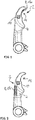
- the data generation unit 2 shown is on a gripping arm 4 of a gripping device 6 (cf. FIGS. 3 and 4 ) arranged.
- the data generation unit 2 is used to generate status data which contain information about a status variable of the gripping device 6 and especially of the gripping arm 4.
- the gripping device 6 serves to grasp, hold and guide particularly bottle-like containers (cf. FIGS. 3 and 4 ).
- the data generation unit 2 has a detection unit 8 for detecting the at least one state variable.
- the at least one state variable can include, for example, a number of gripping cycles of the gripping device 6, a pressure force which acts on the gripping device 6 and in particular on the gripping arm 4, material fatigue / wear and tear and a break in a component of the gripping device 6, in particular the gripping arm 4 be understood.
- the data generation unit 2 has a data preprocessing unit 10 for generating the status data.
- the detection unit 8 is formed by a sensor 12 a which is arranged in a gripping section 14 of the gripping arm 4.
- the gripping section 14 is understood here to mean the section of the gripping arm 4 with which the particularly bottle-like containers are gripped, that is to say with which the particularly bottle-like containers come into mechanical contact.
- the detection unit 8 can alternatively or additionally have further sensors 12.
- the sensor 12a is designed as a resistive sensor which generates a sensor signal based on the electrical resistance and / or based on a change in the electrical resistance. Due to the fact that the resistive sensor 12a is arranged in the gripping section 14 of the gripping arm 4, it also comes into mechanical contact with the particularly bottle-like containers (not shown) and is subject to mechanical wear. Due to mechanical wear and tear Material is also removed from the sensor 12, which leads to a change in the electrical resistance. This change in the electrical resistance can in turn be determined in the form of a change in the detected signal.
- the resistive sensor 12a In order to transmit the detected electrical resistance of the resistive sensor 12a to the data preprocessing unit 10, the resistive sensor 12a and thus the detection unit 8 are connected to the data preprocessing unit 10 (not shown here).
- the state variable to be detected which in this case is the already mentioned material fatigue / wear, is thus correlated with the detected electrical resistance value of the resistive sensor 12a.
- a breakage of a component and in particular a breakage of the gripping arm 4 of the gripping device 6 can also be detected in this way.
- Fig. 2 shows a gripping arm 4 with a data generation unit 2 according to a second embodiment.
- the gripping arm 4 here is structurally identical to the gripping arms 4 according to FIG Fig. 1 educated.
- the data preprocessing unit 10 corresponds to the data preprocessing unit 10 according to FIG Fig. 1 .
- the detection unit 8 is formed as a strain gauge 12b.
- a strain gauge 12b is an embodiment of a resistive sensor 12a, the ascertainable resistance value of which varies as a function of an expansion or compression of the strain gauge 12b.
- the strain gauge 12b is arranged on one side of the gripping arm 4.
- a compressive force on the gripping arm 4 can be determined which leads to an expansion or compression of the gripping arm 4.
- This expansion or compression is in turn transferred to the strain gauges 12b arranged on the gripping arms and can thereby be determined.
- the detected electrical resistance value or the detected change in the electrical resistance are transmitted to the data preprocessing unit 10.
- several strain gauges 12b can also be arranged on the surface of the gripper arm 4. This enables, in particular, a local resolution of the compressive force acting in each case.
- An external influence can also be determined by means of the detection unit 8 embodied as a strain gauge 12b. Under the external influence, how can already mentioned above - for example a pressure force which does not occur during normal operation of the gripping device 6. For example, an unusually high compressive force occurs when someone steps on the gripping device 6 and especially on the gripping arm 4.
- Fig. 3 shows a gripping device 6 with two opposing gripping arms 4 and a detection unit 8 with several sensors 12a, 12b, 12c.
- a strain gauge 12b is arranged on each of the gripping arms 4.
- each gripping section 14 has a resistive sensor 12a for detecting material fatigue / wear within the gripping section 14.
- two capacitive sensors 12c are arranged on the gripping device 6 on an outside, that is to say opposite the gripping section 14.
- each gripping arm 4 has a capacitive sensor 12c.
- the two capacitive sensors 12c thus form a plate capacitor whose detectable capacitance value is dependent on a distance between the two capacitive sensors 12c.
- a transport device 16 which has a plurality of gripping devices 6 on the circumferential side. Their gripping arms 4 are directed radially outward. Because of this configuration, the transport device 16 is also referred to as a transport star.
- Each of the gripping devices 6 and especially each gripping arm 4 of the transport device 16 has a data generation unit 2 with a detection unit 8 and a data preprocessing unit 10 (not shown). Alternatively, only one data preprocessing unit 10 is provided for the detection units 8 of the gripping devices 6 of the entire transport device 16.
- the detection units 8 here have at least one of the sensors 12a, 12b, 12c already mentioned above, so that at least one of the state variables also already mentioned can be detected. This configuration makes it possible to detect the state variables of each gripping device 6 and especially even of each gripping arm 4 of the transport device 16 and to make them available for an evaluation.
- the data preprocessing unit 10 is set up to generate state data from the at least one recorded state variable.
- the at least one recorded state variable is only formatted into a data format and made available for transmission by means of a data transmission unit not shown here.
- the at least one recorded state variable can also be pre-filtered before it is converted into the state data.
- the data generation unit 2 can be or is connected to one or more external entities 18.
- an external entity 18 is provided, which is designed as a surveillance system, for example as a surveillance camera.
- the external entity 18 can be activated as a function of the at least one recorded state variable and generates entity data in the process.
- the external entity 18 designed as a camera can be activated and thus provide image data on the cause of the increased pressure load.
- the entity data generated thereby are also part of the status data and are made available for transmission by the data preprocessing unit 10 together with the detected status variable or variables.
Landscapes
- Engineering & Computer Science (AREA)
- Mechanical Engineering (AREA)
- Robotics (AREA)
- Human Computer Interaction (AREA)
- Physics & Mathematics (AREA)
- General Physics & Mathematics (AREA)
- Automation & Control Theory (AREA)
- Manipulator (AREA)
Priority Applications (1)
| Application Number | Priority Date | Filing Date | Title |
|---|---|---|---|
| EP19203237.3A EP3809211B1 (fr) | 2019-10-15 | 2019-10-15 | Système avec une unité de génération des données dans un bras de préhension |
Applications Claiming Priority (1)
| Application Number | Priority Date | Filing Date | Title |
|---|---|---|---|
| EP19203237.3A EP3809211B1 (fr) | 2019-10-15 | 2019-10-15 | Système avec une unité de génération des données dans un bras de préhension |
Publications (2)
| Publication Number | Publication Date |
|---|---|
| EP3809211A1 true EP3809211A1 (fr) | 2021-04-21 |
| EP3809211B1 EP3809211B1 (fr) | 2021-12-15 |
Family
ID=68501320
Family Applications (1)
| Application Number | Title | Priority Date | Filing Date |
|---|---|---|---|
| EP19203237.3A Active EP3809211B1 (fr) | 2019-10-15 | 2019-10-15 | Système avec une unité de génération des données dans un bras de préhension |
Country Status (1)
| Country | Link |
|---|---|
| EP (1) | EP3809211B1 (fr) |
Cited By (1)
| Publication number | Priority date | Publication date | Assignee | Title |
|---|---|---|---|---|
| DE102024135560B3 (de) | 2024-12-02 | 2026-05-07 | Schaeffler Technologies AG & Co. KG | Greifvorrichtung mit in mehreren Schichten im Finger angeordneten bistabilen Magnetdrähten als Sensorvorrichtung und Roboter |
Citations (5)
| Publication number | Priority date | Publication date | Assignee | Title |
|---|---|---|---|---|
| DE29713510U1 (de) | 1997-07-30 | 1998-08-27 | Krones Ag Hermann Kronseder Maschinenfabrik, 93073 Neutraubling | Rotationsfüller |
| WO2006089610A1 (fr) | 2005-02-23 | 2006-08-31 | Krones Ag | Pince de serrage pour un systeme de transport de recipients |
| DE102011002988A1 (de) * | 2011-01-21 | 2012-07-26 | Krones Aktiengesellschaft | Etikettiermaschine für Behälter |
| US20180333857A1 (en) * | 2017-05-19 | 2018-11-22 | Fanuc Corporation | Workpiece picking system |
| DE102019108787A1 (de) * | 2018-04-10 | 2019-10-10 | Fanuc Corporation | Handsteuerungsvorrichtung und Handsteuerungssystem |
-
2019
- 2019-10-15 EP EP19203237.3A patent/EP3809211B1/fr active Active
Patent Citations (5)
| Publication number | Priority date | Publication date | Assignee | Title |
|---|---|---|---|---|
| DE29713510U1 (de) | 1997-07-30 | 1998-08-27 | Krones Ag Hermann Kronseder Maschinenfabrik, 93073 Neutraubling | Rotationsfüller |
| WO2006089610A1 (fr) | 2005-02-23 | 2006-08-31 | Krones Ag | Pince de serrage pour un systeme de transport de recipients |
| DE102011002988A1 (de) * | 2011-01-21 | 2012-07-26 | Krones Aktiengesellschaft | Etikettiermaschine für Behälter |
| US20180333857A1 (en) * | 2017-05-19 | 2018-11-22 | Fanuc Corporation | Workpiece picking system |
| DE102019108787A1 (de) * | 2018-04-10 | 2019-10-10 | Fanuc Corporation | Handsteuerungsvorrichtung und Handsteuerungssystem |
Cited By (1)
| Publication number | Priority date | Publication date | Assignee | Title |
|---|---|---|---|---|
| DE102024135560B3 (de) | 2024-12-02 | 2026-05-07 | Schaeffler Technologies AG & Co. KG | Greifvorrichtung mit in mehreren Schichten im Finger angeordneten bistabilen Magnetdrähten als Sensorvorrichtung und Roboter |
Also Published As
| Publication number | Publication date |
|---|---|
| EP3809211B1 (fr) | 2021-12-15 |
Similar Documents
| Publication | Publication Date | Title |
|---|---|---|
| DE19831372C2 (de) | Vorrichtung zur Kontrolle kraftschlüssiger Verbindungen | |
| EP0796158B1 (fr) | Procede et dispositif de production optimisee de ressorts helicoidaux sur des machines automatiques a enrouler les ressorts | |
| EP3009817B1 (fr) | Systeme de roulement et cage de retenue pour le roulement | |
| EP3030508B1 (fr) | Dispositif et procédé de repérage de défauts pour matériaux en bande | |
| DE102018123799A1 (de) | Gurtabstreifer und Verfahren zum Betrieb eines Gurtabstreifers | |
| DE102015102337A1 (de) | Redundanter Drehmomentsensor - Multiple Bandanordnung | |
| EP1677070B1 (fr) | Procédé et dispositif destinés à la détermination de la flexion d'un élément de liaison | |
| EP3809211B1 (fr) | Système avec une unité de génération des données dans un bras de préhension | |
| DE102016206980A1 (de) | Verfahren zur Handhabung eines Körpers und Handhabungsvorrichtung | |
| WO2016050952A1 (fr) | Système de sécurité mécatronique pour manèges, en particulier montagnes russes, carrousels ou similaires | |
| WO2018158323A1 (fr) | Procédé de contrôle de la capacité de fonctionnement d'une isolation thermique d'un conteneur de transport | |
| EP0967030B1 (fr) | Procédé et dispositif de réglage des rouleaux d'un dispositif de redressage | |
| DE102019118639A1 (de) | Verfahren zur Verschleißüberwachung eines elektromechanischen Aktors für ein Luftfahrzeug | |
| DE102019102395A1 (de) | Verfahren zur detektion von fehlerzuständen in ketten | |
| DE102015010042A1 (de) | Prüfanordnung zur Prüfung mindestens einer Verbindungsschnittstelle und Verfahren zur Prüfung mindestens einer Verbindungsschnittstelle mit einer Prüfanordnung | |
| DE102005026683A1 (de) | Mehrfachblattzuführungs-Erkennungsvorrichtung, Sortierer und Verfahren zur Erkennung der Mehrfachblattzuführung | |
| DE10101925B4 (de) | Taststift | |
| DE102016204314A1 (de) | Linearbewegungsvorrichtung mit flächigem Dehnungssensor | |
| DE102020117972A1 (de) | Überwachungsvorrichtung und Verfahren zur Überwachung des Zustands eines Förderbands einer Förderbandanlage | |
| DE102015213402A1 (de) | Greifersystem | |
| DE102018132139A1 (de) | Verfahren zur Detektion und Kommunikation von Fehlerzuständen in Ketten | |
| DE102008046172B4 (de) | Vorrichtung und Verfahren zur Überwachung des Behältertransports bei einer Fördereinrichtung für Behälter und/oder Gebinde | |
| DE102023116060A1 (de) | Klammervorrichtung zum Halten eines Behälters, Steuernocken und Behälterbehandlungsvorrichtung | |
| DE102011001169B4 (de) | Sicherheitseinrichtung und Verfahren zur Verwendung einer Sicherheitseinrichtung | |
| DE102019111042A1 (de) | Strukturüberwachungssystem und Strukturüberwachungsverfahren |
Legal Events
| Date | Code | Title | Description |
|---|---|---|---|
| STAA | Information on the status of an ep patent application or granted ep patent |
Free format text: STATUS: EXAMINATION IS IN PROGRESS |
|
| PUAI | Public reference made under article 153(3) epc to a published international application that has entered the european phase |
Free format text: ORIGINAL CODE: 0009012 |
|
| 17P | Request for examination filed |
Effective date: 20200702 |
|
| AK | Designated contracting states |
Kind code of ref document: A1 Designated state(s): AL AT BE BG CH CY CZ DE DK EE ES FI FR GB GR HR HU IE IS IT LI LT LU LV MC MK MT NL NO PL PT RO RS SE SI SK SM TR |
|
| AX | Request for extension of the european patent |
Extension state: BA ME |
|
| GRAP | Despatch of communication of intention to grant a patent |
Free format text: ORIGINAL CODE: EPIDOSNIGR1 |
|
| STAA | Information on the status of an ep patent application or granted ep patent |
Free format text: STATUS: GRANT OF PATENT IS INTENDED |
|
| INTG | Intention to grant announced |
Effective date: 20210930 |
|
| GRAS | Grant fee paid |
Free format text: ORIGINAL CODE: EPIDOSNIGR3 |
|
| GRAA | (expected) grant |
Free format text: ORIGINAL CODE: 0009210 |
|
| STAA | Information on the status of an ep patent application or granted ep patent |
Free format text: STATUS: THE PATENT HAS BEEN GRANTED |
|
| AK | Designated contracting states |
Kind code of ref document: B1 Designated state(s): AL AT BE BG CH CY CZ DE DK EE ES FI FR GB GR HR HU IE IS IT LI LT LU LV MC MK MT NL NO PL PT RO RS SE SI SK SM TR |
|
| REG | Reference to a national code |
Ref country code: GB Ref legal event code: FG4D Free format text: NOT ENGLISH Ref country code: CH Ref legal event code: EP |
|
| REG | Reference to a national code |
Ref country code: DE Ref legal event code: R096 Ref document number: 502019003000 Country of ref document: DE |
|
| REG | Reference to a national code |
Ref country code: IE Ref legal event code: FG4D Free format text: LANGUAGE OF EP DOCUMENT: GERMAN |
|
| REG | Reference to a national code |
Ref country code: AT Ref legal event code: REF Ref document number: 1455950 Country of ref document: AT Kind code of ref document: T Effective date: 20220115 |
|
| REG | Reference to a national code |
Ref country code: LT Ref legal event code: MG9D |
|
| REG | Reference to a national code |
Ref country code: NL Ref legal event code: MP Effective date: 20211215 |
|
| PG25 | Lapsed in a contracting state [announced via postgrant information from national office to epo] |
Ref country code: RS Free format text: LAPSE BECAUSE OF FAILURE TO SUBMIT A TRANSLATION OF THE DESCRIPTION OR TO PAY THE FEE WITHIN THE PRESCRIBED TIME-LIMIT Effective date: 20211215 Ref country code: LT Free format text: LAPSE BECAUSE OF FAILURE TO SUBMIT A TRANSLATION OF THE DESCRIPTION OR TO PAY THE FEE WITHIN THE PRESCRIBED TIME-LIMIT Effective date: 20211215 Ref country code: FI Free format text: LAPSE BECAUSE OF FAILURE TO SUBMIT A TRANSLATION OF THE DESCRIPTION OR TO PAY THE FEE WITHIN THE PRESCRIBED TIME-LIMIT Effective date: 20211215 Ref country code: BG Free format text: LAPSE BECAUSE OF FAILURE TO SUBMIT A TRANSLATION OF THE DESCRIPTION OR TO PAY THE FEE WITHIN THE PRESCRIBED TIME-LIMIT Effective date: 20220315 |
|
| PG25 | Lapsed in a contracting state [announced via postgrant information from national office to epo] |
Ref country code: SE Free format text: LAPSE BECAUSE OF FAILURE TO SUBMIT A TRANSLATION OF THE DESCRIPTION OR TO PAY THE FEE WITHIN THE PRESCRIBED TIME-LIMIT Effective date: 20211215 Ref country code: NO Free format text: LAPSE BECAUSE OF FAILURE TO SUBMIT A TRANSLATION OF THE DESCRIPTION OR TO PAY THE FEE WITHIN THE PRESCRIBED TIME-LIMIT Effective date: 20220315 Ref country code: LV Free format text: LAPSE BECAUSE OF FAILURE TO SUBMIT A TRANSLATION OF THE DESCRIPTION OR TO PAY THE FEE WITHIN THE PRESCRIBED TIME-LIMIT Effective date: 20211215 Ref country code: HR Free format text: LAPSE BECAUSE OF FAILURE TO SUBMIT A TRANSLATION OF THE DESCRIPTION OR TO PAY THE FEE WITHIN THE PRESCRIBED TIME-LIMIT Effective date: 20211215 Ref country code: GR Free format text: LAPSE BECAUSE OF FAILURE TO SUBMIT A TRANSLATION OF THE DESCRIPTION OR TO PAY THE FEE WITHIN THE PRESCRIBED TIME-LIMIT Effective date: 20220316 |
|
| PG25 | Lapsed in a contracting state [announced via postgrant information from national office to epo] |
Ref country code: NL Free format text: LAPSE BECAUSE OF FAILURE TO SUBMIT A TRANSLATION OF THE DESCRIPTION OR TO PAY THE FEE WITHIN THE PRESCRIBED TIME-LIMIT Effective date: 20211215 |
|
| PG25 | Lapsed in a contracting state [announced via postgrant information from national office to epo] |
Ref country code: SM Free format text: LAPSE BECAUSE OF FAILURE TO SUBMIT A TRANSLATION OF THE DESCRIPTION OR TO PAY THE FEE WITHIN THE PRESCRIBED TIME-LIMIT Effective date: 20211215 Ref country code: SK Free format text: LAPSE BECAUSE OF FAILURE TO SUBMIT A TRANSLATION OF THE DESCRIPTION OR TO PAY THE FEE WITHIN THE PRESCRIBED TIME-LIMIT Effective date: 20211215 Ref country code: RO Free format text: LAPSE BECAUSE OF FAILURE TO SUBMIT A TRANSLATION OF THE DESCRIPTION OR TO PAY THE FEE WITHIN THE PRESCRIBED TIME-LIMIT Effective date: 20211215 Ref country code: PT Free format text: LAPSE BECAUSE OF FAILURE TO SUBMIT A TRANSLATION OF THE DESCRIPTION OR TO PAY THE FEE WITHIN THE PRESCRIBED TIME-LIMIT Effective date: 20220418 Ref country code: ES Free format text: LAPSE BECAUSE OF FAILURE TO SUBMIT A TRANSLATION OF THE DESCRIPTION OR TO PAY THE FEE WITHIN THE PRESCRIBED TIME-LIMIT Effective date: 20211215 Ref country code: EE Free format text: LAPSE BECAUSE OF FAILURE TO SUBMIT A TRANSLATION OF THE DESCRIPTION OR TO PAY THE FEE WITHIN THE PRESCRIBED TIME-LIMIT Effective date: 20211215 Ref country code: CZ Free format text: LAPSE BECAUSE OF FAILURE TO SUBMIT A TRANSLATION OF THE DESCRIPTION OR TO PAY THE FEE WITHIN THE PRESCRIBED TIME-LIMIT Effective date: 20211215 |
|
| PG25 | Lapsed in a contracting state [announced via postgrant information from national office to epo] |
Ref country code: PL Free format text: LAPSE BECAUSE OF FAILURE TO SUBMIT A TRANSLATION OF THE DESCRIPTION OR TO PAY THE FEE WITHIN THE PRESCRIBED TIME-LIMIT Effective date: 20211215 |
|
| REG | Reference to a national code |
Ref country code: DE Ref legal event code: R097 Ref document number: 502019003000 Country of ref document: DE |
|
| PG25 | Lapsed in a contracting state [announced via postgrant information from national office to epo] |
Ref country code: IS Free format text: LAPSE BECAUSE OF FAILURE TO SUBMIT A TRANSLATION OF THE DESCRIPTION OR TO PAY THE FEE WITHIN THE PRESCRIBED TIME-LIMIT Effective date: 20220415 |
|
| PLBE | No opposition filed within time limit |
Free format text: ORIGINAL CODE: 0009261 |
|
| STAA | Information on the status of an ep patent application or granted ep patent |
Free format text: STATUS: NO OPPOSITION FILED WITHIN TIME LIMIT |
|
| PG25 | Lapsed in a contracting state [announced via postgrant information from national office to epo] |
Ref country code: DK Free format text: LAPSE BECAUSE OF FAILURE TO SUBMIT A TRANSLATION OF THE DESCRIPTION OR TO PAY THE FEE WITHIN THE PRESCRIBED TIME-LIMIT Effective date: 20211215 Ref country code: AL Free format text: LAPSE BECAUSE OF FAILURE TO SUBMIT A TRANSLATION OF THE DESCRIPTION OR TO PAY THE FEE WITHIN THE PRESCRIBED TIME-LIMIT Effective date: 20211215 |
|
| 26N | No opposition filed |
Effective date: 20220916 |
|
| PG25 | Lapsed in a contracting state [announced via postgrant information from national office to epo] |
Ref country code: MC Free format text: LAPSE BECAUSE OF FAILURE TO SUBMIT A TRANSLATION OF THE DESCRIPTION OR TO PAY THE FEE WITHIN THE PRESCRIBED TIME-LIMIT Effective date: 20211215 |
|
| REG | Reference to a national code |
Ref country code: CH Ref legal event code: PL |
|
| REG | Reference to a national code |
Ref country code: BE Ref legal event code: MM Effective date: 20221031 |
|
| PG25 | Lapsed in a contracting state [announced via postgrant information from national office to epo] |
Ref country code: LU Free format text: LAPSE BECAUSE OF NON-PAYMENT OF DUE FEES Effective date: 20221015 |
|
| PG25 | Lapsed in a contracting state [announced via postgrant information from national office to epo] |
Ref country code: LI Free format text: LAPSE BECAUSE OF NON-PAYMENT OF DUE FEES Effective date: 20221031 Ref country code: CH Free format text: LAPSE BECAUSE OF NON-PAYMENT OF DUE FEES Effective date: 20221031 |
|
| PG25 | Lapsed in a contracting state [announced via postgrant information from national office to epo] |
Ref country code: BE Free format text: LAPSE BECAUSE OF NON-PAYMENT OF DUE FEES Effective date: 20221031 |
|
| PG25 | Lapsed in a contracting state [announced via postgrant information from national office to epo] |
Ref country code: IE Free format text: LAPSE BECAUSE OF NON-PAYMENT OF DUE FEES Effective date: 20221015 |
|
| PG25 | Lapsed in a contracting state [announced via postgrant information from national office to epo] |
Ref country code: CY Free format text: LAPSE BECAUSE OF FAILURE TO SUBMIT A TRANSLATION OF THE DESCRIPTION OR TO PAY THE FEE WITHIN THE PRESCRIBED TIME-LIMIT Effective date: 20211215 |
|
| PG25 | Lapsed in a contracting state [announced via postgrant information from national office to epo] |
Ref country code: MK Free format text: LAPSE BECAUSE OF FAILURE TO SUBMIT A TRANSLATION OF THE DESCRIPTION OR TO PAY THE FEE WITHIN THE PRESCRIBED TIME-LIMIT Effective date: 20211215 Ref country code: HU Free format text: LAPSE BECAUSE OF FAILURE TO SUBMIT A TRANSLATION OF THE DESCRIPTION OR TO PAY THE FEE WITHIN THE PRESCRIBED TIME-LIMIT; INVALID AB INITIO Effective date: 20191015 |
|
| GBPC | Gb: european patent ceased through non-payment of renewal fee |
Effective date: 20231015 |
|
| PG25 | Lapsed in a contracting state [announced via postgrant information from national office to epo] |
Ref country code: GB Free format text: LAPSE BECAUSE OF NON-PAYMENT OF DUE FEES Effective date: 20231015 |
|
| PG25 | Lapsed in a contracting state [announced via postgrant information from national office to epo] |
Ref country code: GB Free format text: LAPSE BECAUSE OF NON-PAYMENT OF DUE FEES Effective date: 20231015 |
|
| PG25 | Lapsed in a contracting state [announced via postgrant information from national office to epo] |
Ref country code: MT Free format text: LAPSE BECAUSE OF FAILURE TO SUBMIT A TRANSLATION OF THE DESCRIPTION OR TO PAY THE FEE WITHIN THE PRESCRIBED TIME-LIMIT Effective date: 20211215 |
|
| REG | Reference to a national code |
Ref country code: DE Ref legal event code: R081 Ref document number: 502019003000 Country of ref document: DE Owner name: TYROLON GMBH, AT Free format text: FORMER OWNER: TYROLON-SCHULNIG GMBH, HOCHFILZEN, AT |
|
| PG25 | Lapsed in a contracting state [announced via postgrant information from national office to epo] |
Ref country code: TR Free format text: LAPSE BECAUSE OF FAILURE TO SUBMIT A TRANSLATION OF THE DESCRIPTION OR TO PAY THE FEE WITHIN THE PRESCRIBED TIME-LIMIT Effective date: 20211215 |
|
| PGFP | Annual fee paid to national office [announced via postgrant information from national office to epo] |
Ref country code: DE Payment date: 20251030 Year of fee payment: 7 |
|
| PGFP | Annual fee paid to national office [announced via postgrant information from national office to epo] |
Ref country code: AT Payment date: 20250917 Year of fee payment: 7 |
|
| PGFP | Annual fee paid to national office [announced via postgrant information from national office to epo] |
Ref country code: IT Payment date: 20251022 Year of fee payment: 7 |
|
| PGFP | Annual fee paid to national office [announced via postgrant information from national office to epo] |
Ref country code: FR Payment date: 20251027 Year of fee payment: 7 |
|
| PG25 | Lapsed in a contracting state [announced via postgrant information from national office to epo] |
Ref country code: SI Free format text: LAPSE BECAUSE OF FAILURE TO SUBMIT A TRANSLATION OF THE DESCRIPTION OR TO PAY THE FEE WITHIN THE PRESCRIBED TIME-LIMIT Effective date: 20211215 |