EP3809545A1 - Dispositif pour déterminer une position d'au moins une partie de l'appareil derrière une surface - Google Patents
Dispositif pour déterminer une position d'au moins une partie de l'appareil derrière une surface Download PDFInfo
- Publication number
- EP3809545A1 EP3809545A1 EP20201996.4A EP20201996A EP3809545A1 EP 3809545 A1 EP3809545 A1 EP 3809545A1 EP 20201996 A EP20201996 A EP 20201996A EP 3809545 A1 EP3809545 A1 EP 3809545A1
- Authority
- EP
- European Patent Office
- Prior art keywords
- ribbon
- shaped body
- transmission line
- antenna
- signal generator
- Prior art date
- Legal status (The legal status is an assumption and is not a legal conclusion. Google has not performed a legal analysis and makes no representation as to the accuracy of the status listed.)
- Withdrawn
Links
- 230000005540 biological transmission Effects 0.000 claims abstract description 37
- 238000001514 detection method Methods 0.000 claims abstract description 10
- 238000006073 displacement reaction Methods 0.000 claims abstract description 3
- 230000005672 electromagnetic field Effects 0.000 claims description 16
- 230000008878 coupling Effects 0.000 claims description 9
- 238000010168 coupling process Methods 0.000 claims description 9
- 238000005859 coupling reaction Methods 0.000 claims description 9
- 239000004033 plastic Substances 0.000 claims description 5
- 229920003023 plastic Polymers 0.000 claims description 5
- 239000000835 fiber Substances 0.000 claims description 4
- 239000003365 glass fiber Substances 0.000 claims description 4
- 239000000463 material Substances 0.000 claims description 4
- 229920000049 Carbon (fiber) Polymers 0.000 claims description 2
- 229920006231 aramid fiber Polymers 0.000 claims description 2
- 239000004917 carbon fiber Substances 0.000 claims description 2
- VNWKTOKETHGBQD-UHFFFAOYSA-N methane Chemical compound C VNWKTOKETHGBQD-UHFFFAOYSA-N 0.000 claims description 2
- 238000009434 installation Methods 0.000 description 17
- 239000004020 conductor Substances 0.000 description 9
- 230000004888 barrier function Effects 0.000 description 7
- 239000002184 metal Substances 0.000 description 4
- 229910052751 metal Inorganic materials 0.000 description 4
- RYGMFSIKBFXOCR-UHFFFAOYSA-N Copper Chemical group [Cu] RYGMFSIKBFXOCR-UHFFFAOYSA-N 0.000 description 3
- 239000011152 fibreglass Substances 0.000 description 1
- 230000001939 inductive effect Effects 0.000 description 1
- 238000005259 measurement Methods 0.000 description 1
- 238000000034 method Methods 0.000 description 1
- 230000002787 reinforcement Effects 0.000 description 1
Images


Classifications
-
- H—ELECTRICITY
- H02—GENERATION; CONVERSION OR DISTRIBUTION OF ELECTRIC POWER
- H02G—INSTALLATION OF ELECTRIC CABLES OR LINES, OR OF COMBINED OPTICAL AND ELECTRIC CABLES OR LINES
- H02G1/00—Methods or apparatus specially adapted for installing, maintaining, repairing or dismantling electric cables or lines
- H02G1/06—Methods or apparatus specially adapted for installing, maintaining, repairing or dismantling electric cables or lines for laying cables, e.g. laying apparatus on vehicle
- H02G1/08—Methods or apparatus specially adapted for installing, maintaining, repairing or dismantling electric cables or lines for laying cables, e.g. laying apparatus on vehicle through tubing or conduit, e.g. rod or draw wire for pushing or pulling
- H02G1/081—Methods or apparatus specially adapted for installing, maintaining, repairing or dismantling electric cables or lines for laying cables, e.g. laying apparatus on vehicle through tubing or conduit, e.g. rod or draw wire for pushing or pulling using pulling means at cable ends, e.g. pulling eyes or anchors
-
- G—PHYSICS
- G01—MEASURING; TESTING
- G01V—GEOPHYSICS; GRAVITATIONAL MEASUREMENTS; DETECTING MASSES OR OBJECTS; TAGS
- G01V3/00—Electric or magnetic prospecting or detecting; Measuring magnetic field characteristics of the earth, e.g. declination, deviation
- G01V3/12—Electric or magnetic prospecting or detecting; Measuring magnetic field characteristics of the earth, e.g. declination, deviation operating with electromagnetic waves
-
- H—ELECTRICITY
- H02—GENERATION; CONVERSION OR DISTRIBUTION OF ELECTRIC POWER
- H02G—INSTALLATION OF ELECTRIC CABLES OR LINES, OR OF COMBINED OPTICAL AND ELECTRIC CABLES OR LINES
- H02G3/00—Installations of electric cables or lines or protective tubing therefor in or on buildings, equivalent structures or vehicles
- H02G3/36—Installations of cables or lines in walls, floors or ceilings
- H02G3/38—Installations of cables or lines in walls, floors or ceilings the cables or lines being installed in preestablished conduits or ducts
Definitions
- the invention relates to a device provided with a ribbon-shaped body, such as a cable or spring, which ribbon-shaped body is intended for displacement behind a surface, such as a surface of a wall, floor or ceiling, by means of a pulling or pushing movement, in which a first free end of the ribbon-shaped body is provided with a head, wherein the device also comprises position determining means for determining the position of at least a part of the ribbon-shaped body, wherein the position determining means comprise a signal generator for generating an alternating electrical signal, transmitting means for generating an electromagnetic field based on the alternating electrical signal, wherein the transmitting means are arranged on the ribbon-shaped body, and comprise detection means which are arranged for detecting the electromagnetic field, wherein the field strength of the electromagnetic field is such that the electromagnetic field is detectable by the detection means.
- the device according to the preamble is known in the art and is e.g. referred to as a tension spring or push spring.
- the known device is used to provide installation wires (such as power wires) in a wall of a building in an installation tube.
- installation wires such as power wires
- an installation wire is coupled to the head of the ribbon-shaped body, after which the installation wire by means of the ribbon-shaped body is pushed or pulled through the installation tube from a first open end to a second open end.
- the barrier In practice, there are sometimes barriers in the installation tube that block the passage for the ribbon-shaped body. In this case, the barrier must first be removed by, for example, making a hole in the wall at the location of the barrier. The location of the barrier should be known accurately for this purpose.
- the transmitting means are formed by an electrically conductive wire which is placed in the ribbon-shaped body.
- the signal generator is thereby arranged for generating an RF signal lower than the MF (MW) range.
- the detection means are arranged to receive the electromagnetic field generated when the RF signal is passed through the conductive wire.
- the known device has the drawback that the measurement results are influenced by metal conductors in the environment, such as concrete reinforcement or another metal wiring, which are located in the vicinity of the conductive wire. Due to inductive coupling between the conductive wire and the metal conductors, the metal conductors in use also emit the RF signal, which negatively influences the accuracy, reliability and speed of the position determination.
- the invention has for its object to provide a device according to the preamble in which the above-mentioned disadvantages are eliminated.
- the device has the feature that the transmitting means comprise an antenna, which antenna is arranged in the head of the ribbon-shaped body, and that the device further comprises a transmission line, in which an input of the transmission line is coupled to the signal generator and an output from the transmission line is coupled to the antenna.
- the alternating electrical signal can be transported from the signal generator to the antenna with minimal losses.
- the antenna will subsequently generate an electromagnetic field substantially only at the location of the head, whereby the actual position of the head of the ribbon-shaped body can be accurately determined at any invisible position behind a surface, for example in a tube.
- the course of the tube can be determined.
- the position of a possible barrier present in the tube can also be accurately determined.
- the ribbon-shaped body preferably at the location of the head, is arranged for coupling to a wire for installing, maintaining, repairing or removing the wire behind the surface.
- the antenna is directional, so that an electromagnetic field can be generated that is substantially perpendicular to the longitudinal direction of the ribbon-shaped body.
- the signal generator is arranged to generate an alternating electrical RF signal.
- the device according to the invention can be used in a large frequency range, wherein the signal generator requires little power. It is expected that a few penlight batteries are sufficient to measure many times longer than the known device.
- the alternating electrical RF signal has a frequency of 10 MHz or higher. In this frequency range there will be very little crosstalk, which allows positioning with very high accuracy.
- the signal generator is arranged to generate the alternating electrical signal with a frequency lower than the MF (MW) range, preferably substantially 33 kHz. In the device according to the invention less cross-talk will occur compared to the known device, which enables a precise detection.
- the transmission line comprises a coaxial cable.
- the transmission line is formed by a balanced, parallel transmission line.
- the transmission line comprises two electrically conductive wires, which are twisted over substantially the length of the transmission line.
- the ribbon-shaped body and the transmission line are at least partially connected when viewed from the head.
- the ribbon-shaped body surrounds the transmission line.
- the ribbon-shaped body comprises a plastic outer jacket.
- the space between the outer jacket and the transmission line comprises a fiber-reinforced material, comprising glass fiber, aramid fiber, carbon fiber or plastic fiber.
- the invention also relates to a ribbon-shaped body as described as part of the device according to the invention.
- FIG. 1A shows a first preferred embodiment of the device 1.
- the device 1 comprises a ribbon-shaped body 2, which is provided with a head 8.
- the first and the second end of the ribbon-shaped body 2 are shown in the figure.
- the body 2 can be arranged by a user of the device 1 at a non-visible location, for example behind a surface or in an installation tube (not shown).
- the head may encounter a barrier during movement.
- the position determining means comprises a signal generator 100, which generates an electrical RF signal.
- the position determining means further comprise a coaxial transmission line, formed by an outer jacket 5, dielectric 6 and copper core 7.
- the coaxial transmission line is arranged in the ribbon-shaped body 2.
- a first input side of the copper core 7 is connected to the signal generator 100.
- the position determining means comprise an antenna 200 integrated in the head 8.
- the antenna 200 is connected to a second output side of the copper core 7.
- the signal generator 100 is activated, which then generates an alternating electrical signal with said frequency.
- This signal is routed through the coaxial transmission line without electromagnetic interference to the antenna 200, after which the antenna 200 converts the electrical signal into an electromagnetic field.
- the position determining means comprise detection means 400 which are arranged for detecting the electromagnetic field 300.
- the detection means 400 are provided with a receiving antenna (not shown), which is tuned to the frequency of the electromagnetic field 300, and with means (not shown) for outputting a detection signal related to the field strength of the received electromagnetic field 300.
- Figure 1B shows a cross-section of the ribbon-shaped body 2 of the first preferred embodiment of the device 1.
- the coaxial transmission line is arranged in the ribbon-shaped body 2.
- the coaxial transmission line is jacketed by a profile of fiber reinforced material, for example a glass fiber profile 4, in which the fibers of the fiber glass profile 4 run parallel to the longitudinal direction of the ribbon-shaped body 2.
- a profile of fiber reinforced material for example a glass fiber profile 4, in which the fibers of the fiber glass profile 4 run parallel to the longitudinal direction of the ribbon-shaped body 2.
- the ribbon-shaped body 2 is provided with a plastic outer jacket 3.
- the properties of the materials and dimensions of the components of the ribbon-shaped body 2 are chosen in such a way that the ribbon-shaped body 2 has the function of a tension or push spring.
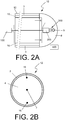
- Figure 2A shows a second preferred embodiment of the device 10, in which the first and the second end of the ribbon-shaped body 12 are shown.
- the second preferred embodiment of the device 10 has as an alternative to the coaxial transmission line of the first preferred embodiment 1 a balanced parallel transmission line formed by the electrically conductive wires 7, 15, 16.
- the electrically conductive wires 15 and 16 are located on the outside and are referred to as outer conductors.
- the electrically conductive wire 7 is centrally located between the outer conductors 15 and 16. In a balanced parallel transmission line, an equal but opposite current flows in each outer conductor 15, 16. In addition, over each outer conductor 15, 16 there is an equal, but opposite voltage to earth or the surrounding area around the conductor.
- Figure 2B shows a cross-section of the ribbon-shaped body 12 of the second preferred embodiment of the device 10, in which the positions of the electrically conductive wires 7, 15 and 16 are shown.
- Figure 3A shows a third preferred embodiment of the device 20, in which the first and the second end of the ribbon-shaped body 22 is shown.
- the second preferred embodiment of the apparatus 20 has a transmission line that is formed by a twisted pair of electrically conductive wires 24, 25.
- the wires 24, 25 are wound around each other, thereby avoiding electromagnetic interference (crosstalk).
- the wires 24, 25 are preferably contained in a jacket 26.
- Figure 3B shows a cross-section of the ribbon-shaped body 22 of the second preferred embodiment of the device 20, in which the positions of the electrically conductive wires 24, 25 are shown.
- the head 8 of the ribbon-shaped body 2, 12, 20 comprises a coupling element 9, for example an eye, for coupling an installation wire.
- a user can attach the installation wire to the coupling element 9.
- the installation wire can then be pushed through an installation tube simultaneously with the ribbon-shaped body 2, 12, 20.
- the ribbon-shaped body 2, 12, 20 can first be passed through the installation tube, after which the installation wire is attached to the coupling element 9. By subsequently removing the ribbon-shaped body from the installation tube in the opposite direction, the installation wire is pulled through the installation tube.
- the eye is only an example of a suitable coupling element for an installation wire.
- the coupling element is also optional.
Landscapes
- Physics & Mathematics (AREA)
- Engineering & Computer Science (AREA)
- Remote Sensing (AREA)
- Life Sciences & Earth Sciences (AREA)
- Electromagnetism (AREA)
- Environmental & Geological Engineering (AREA)
- Geology (AREA)
- General Life Sciences & Earth Sciences (AREA)
- General Physics & Mathematics (AREA)
- Geophysics (AREA)
- Measurement Of Length, Angles, Or The Like Using Electric Or Magnetic Means (AREA)
- Near-Field Transmission Systems (AREA)
Applications Claiming Priority (1)
| Application Number | Priority Date | Filing Date | Title |
|---|---|---|---|
| NL2024055A NL2024055B1 (nl) | 2019-10-18 | 2019-10-18 | Inrichting voor het bepalen van een positie van althans een deel van de inrichting achter een oppervlak |
Publications (1)
| Publication Number | Publication Date |
|---|---|
| EP3809545A1 true EP3809545A1 (fr) | 2021-04-21 |
Family
ID=73020038
Family Applications (1)
| Application Number | Title | Priority Date | Filing Date |
|---|---|---|---|
| EP20201996.4A Withdrawn EP3809545A1 (fr) | 2019-10-18 | 2020-10-15 | Dispositif pour déterminer une position d'au moins une partie de l'appareil derrière une surface |
Country Status (2)
| Country | Link |
|---|---|
| EP (1) | EP3809545A1 (fr) |
| NL (1) | NL2024055B1 (fr) |
Citations (4)
| Publication number | Priority date | Publication date | Assignee | Title |
|---|---|---|---|---|
| FR1572299A (fr) * | 1968-03-22 | 1969-06-27 | ||
| SE441048B (sv) * | 1978-09-15 | 1985-09-02 | Allan J E Holmgren | Anordning for lokalisering av stopp i ror |
| GB2353098A (en) * | 1999-08-11 | 2001-02-14 | Cary Knapton | Cable installation aid |
| US7150448B1 (en) * | 2005-10-19 | 2006-12-19 | Swift Richard C | Fish tape having electrical box locator circuit and method therefor |
-
2019
- 2019-10-18 NL NL2024055A patent/NL2024055B1/nl not_active IP Right Cessation
-
2020
- 2020-10-15 EP EP20201996.4A patent/EP3809545A1/fr not_active Withdrawn
Patent Citations (4)
| Publication number | Priority date | Publication date | Assignee | Title |
|---|---|---|---|---|
| FR1572299A (fr) * | 1968-03-22 | 1969-06-27 | ||
| SE441048B (sv) * | 1978-09-15 | 1985-09-02 | Allan J E Holmgren | Anordning for lokalisering av stopp i ror |
| GB2353098A (en) * | 1999-08-11 | 2001-02-14 | Cary Knapton | Cable installation aid |
| US7150448B1 (en) * | 2005-10-19 | 2006-12-19 | Swift Richard C | Fish tape having electrical box locator circuit and method therefor |
Also Published As
| Publication number | Publication date |
|---|---|
| NL2024055B1 (nl) | 2021-06-22 |
Similar Documents
| Publication | Publication Date | Title |
|---|---|---|
| RU2547143C2 (ru) | Способ измерения длины электрического кабеля, который использует оптоволоконный элемент в качестве датчика | |
| JP5723089B2 (ja) | 電磁界センサ及び受信器 | |
| US20100281684A1 (en) | Cable harness production system | |
| EP0784210A3 (fr) | Appareil pour détecter l'endroit d'un défaut dans un faisceau de câbles | |
| EP1214501B1 (fr) | Appareil et procedes lies au operations de fond | |
| CN102331549A (zh) | 电气故障位置确定 | |
| US20040016566A1 (en) | Detectable cable tape | |
| CN103109198B (zh) | 通过反射法检测电缺陷的方法和结构 | |
| TWI817067B (zh) | 用於高架電纜之入埠硬體、用於端接高架電纜的方法及用於通過端接配置來查詢高架電纜的方法 | |
| US7526163B2 (en) | Locatable cables and cable components therefor | |
| CN104713617B (zh) | 用于波导的重块设备、探测设备和用于制造重块设备的方法 | |
| CN108461206B (zh) | 电力传导元件和用于绝缘监测的系统 | |
| NL2024055B1 (nl) | Inrichting voor het bepalen van een positie van althans een deel van de inrichting achter een oppervlak | |
| JP5488891B2 (ja) | ケーブル接続確認装置 | |
| JP5089503B2 (ja) | ケーブル探査方法及びケーブル探査装置 | |
| KR101445083B1 (ko) | 전원 분전함 내부 설치형 부분 방전 검출 방법 | |
| US20090314513A1 (en) | Toneable conduit with loose toning signal wire | |
| US10295389B2 (en) | Fill level measurement device | |
| US20090045808A1 (en) | System for testing concealed conduits | |
| EP3106888A1 (fr) | Procédé et système de mesure de décharge partielle sur un câble d'alimentation | |
| JP2011080896A (ja) | ケーブル検出方法 | |
| EP0102672B1 (fr) | Système de transmission pour l'examen du sol | |
| RU2751109C1 (ru) | Способ поиска трассы прокладки и определения глубины прокладки пакета микротрубок без металлических элементов на волоконно-оптической линии связи | |
| US8875580B2 (en) | Method and apparatus to detect wire pathologies near crimped connector | |
| JP5506607B2 (ja) | シールド部材の異常検出方法及びシールド部材の異常検出装置 |
Legal Events
| Date | Code | Title | Description |
|---|---|---|---|
| PUAI | Public reference made under article 153(3) epc to a published international application that has entered the european phase |
Free format text: ORIGINAL CODE: 0009012 |
|
| STAA | Information on the status of an ep patent application or granted ep patent |
Free format text: STATUS: THE APPLICATION HAS BEEN PUBLISHED |
|
| AK | Designated contracting states |
Kind code of ref document: A1 Designated state(s): AL AT BE BG CH CY CZ DE DK EE ES FI FR GB GR HR HU IE IS IT LI LT LU LV MC MK MT NL NO PL PT RO RS SE SI SK SM TR |
|
| AX | Request for extension of the european patent |
Extension state: BA ME |
|
| STAA | Information on the status of an ep patent application or granted ep patent |
Free format text: STATUS: THE APPLICATION IS DEEMED TO BE WITHDRAWN |
|
| 18D | Application deemed to be withdrawn |
Effective date: 20211022 |