EP3809557A1 - Dispositif d'éclairage d'urgence bidirectionnel - Google Patents
Dispositif d'éclairage d'urgence bidirectionnel Download PDFInfo
- Publication number
- EP3809557A1 EP3809557A1 EP19203202.7A EP19203202A EP3809557A1 EP 3809557 A1 EP3809557 A1 EP 3809557A1 EP 19203202 A EP19203202 A EP 19203202A EP 3809557 A1 EP3809557 A1 EP 3809557A1
- Authority
- EP
- European Patent Office
- Prior art keywords
- secondary side
- emergency lighting
- lighting driver
- emergency
- battery
- Prior art date
- Legal status (The legal status is an assumption and is not a legal conclusion. Google has not performed a legal analysis and makes no representation as to the accuracy of the status listed.)
- Withdrawn
Links
Images



Classifications
-
- H—ELECTRICITY
- H05—ELECTRIC TECHNIQUES NOT OTHERWISE PROVIDED FOR
- H05B—ELECTRIC HEATING; ELECTRIC LIGHT SOURCES NOT OTHERWISE PROVIDED FOR; CIRCUIT ARRANGEMENTS FOR ELECTRIC LIGHT SOURCES, IN GENERAL
- H05B45/00—Circuit arrangements for operating light-emitting diodes [LED]
- H05B45/30—Driver circuits
- H05B45/37—Converter circuits
- H05B45/3725—Switched mode power supply [SMPS]
- H05B45/385—Switched mode power supply [SMPS] using flyback topology
-
- H—ELECTRICITY
- H05—ELECTRIC TECHNIQUES NOT OTHERWISE PROVIDED FOR
- H05B—ELECTRIC HEATING; ELECTRIC LIGHT SOURCES NOT OTHERWISE PROVIDED FOR; CIRCUIT ARRANGEMENTS FOR ELECTRIC LIGHT SOURCES, IN GENERAL
- H05B47/00—Circuit arrangements for operating light sources in general, i.e. where the type of light source is not relevant
- H05B47/10—Controlling the light source
- H05B47/175—Controlling the light source by remote control
- H05B47/18—Controlling the light source by remote control via data-bus transmission
- H05B47/183—Controlling the light source by remote control via data-bus transmission using digital addressable lighting interface [DALI] communication protocols
-
- H—ELECTRICITY
- H05—ELECTRIC TECHNIQUES NOT OTHERWISE PROVIDED FOR
- H05B—ELECTRIC HEATING; ELECTRIC LIGHT SOURCES NOT OTHERWISE PROVIDED FOR; CIRCUIT ARRANGEMENTS FOR ELECTRIC LIGHT SOURCES, IN GENERAL
- H05B47/00—Circuit arrangements for operating light sources in general, i.e. where the type of light source is not relevant
- H05B47/10—Controlling the light source
- H05B47/17—Operational modes, e.g. switching from manual to automatic mode or prohibiting specific operations
- H05B47/172—Emergency operational modes
-
- Y—GENERAL TAGGING OF NEW TECHNOLOGICAL DEVELOPMENTS; GENERAL TAGGING OF CROSS-SECTIONAL TECHNOLOGIES SPANNING OVER SEVERAL SECTIONS OF THE IPC; TECHNICAL SUBJECTS COVERED BY FORMER USPC CROSS-REFERENCE ART COLLECTIONS [XRACs] AND DIGESTS
- Y02—TECHNOLOGIES OR APPLICATIONS FOR MITIGATION OR ADAPTATION AGAINST CLIMATE CHANGE
- Y02B—CLIMATE CHANGE MITIGATION TECHNOLOGIES RELATED TO BUILDINGS, e.g. HOUSING, HOUSE APPLIANCES OR RELATED END-USER APPLICATIONS
- Y02B20/00—Energy efficient lighting technologies, e.g. halogen lamps or gas discharge lamps
- Y02B20/30—Semiconductor lamps, e.g. solid state lamps [SSL] light emitting diodes [LED] or organic LED [OLED]
Definitions
- the invention relates to an emergency lighting device, especially a DALI-bus compatible emergency lighting device.
- DALI bus power supply provided as a separate device from the emergency lighting driver is powerless. This leads to the situation that a communication through the DALI bus is no longer possible.
- the object of the invention is to provide an emergency lighting driver, which allows for a communication over the DALI bus during emergency states.
- an emergency lighting driver comprises a bi-directional flyback converter, comprising a primary side and a secondary side. Moreover, the emergency lighting driver comprises an integrated DALI power supply.
- the bi-directional flyback converter is adapted to, in a non-emergency state, provide energy from the primary side to the secondary side, and in an emergency state, provide energy from the secondary side to the integrated DALI power supply connected to the primary side. This allows for a supply of operating voltage to the DALI bus even in emergency states.
- an emergency state is defined by a loss of mains power, wherein a non-emergency state is defined by an availability of mains power. This allows for a clear differentiation between an emergency state and a non-emergency state.
- the bi-directional flyback converter comprises a transformer, comprising on the secondary side, a secondary side winding and an auxiliary secondary side winding connected in series to the secondary side winding.
- the secondary side of the bi-directional flyback converter moreover comprises an auxiliary secondary side winding flyback switch, connected between the auxiliary secondary side winding and ground, and an auxiliary secondary side winding bypass switch, connected between ground and a connection node between the secondary side winding and the auxiliary secondary side winding. This allows for an integration and a bypassing of the auxiliary secondary side winding.
- the emergency lighting driver is adapted to open the auxiliary secondary side winding flyback switch and close the auxiliary secondary side winding bypass switch.
- the emergency lighting driver is adapted to switch the auxiliary secondary side winding flyback switch repeatedly in a flyback operation, and open the auxiliary secondary side winding bypass switch. This clearly bypasses the auxiliary secondary side winding during non-emergency operation and clearly integrates the auxiliary secondary side winding in the emergency state.
- the transformer comprises on the primary side an auxiliary primary side winding, connected to the integrated DALI power supply.
- the emergency lighting driver is adapted to transfer energy from the auxiliary secondary side winding to the auxiliary primary side winding. This allows for a bi-directional operation of the converter.
- the emergency lighting driver additionally comprises a battery switch connected to the secondary side, which is connectable to a battery.
- the emergency lighting driver is adapted to, in the emergency state, close the battery switch, directly connecting the battery to the secondary side, and in the non-emergency state, open the battery switch, opening the direct connection of the battery to the secondary side. This allows for a direct powering of the secondary side of the bi-directional flyback converter by the battery during the emergency state.
- the battery is protected from over-charging, which would occur due to a continuous direct connection to the secondary side.
- the emergency lighting driver additionally comprises a battery charger, which is connected to the secondary side and which is connectable to the battery.
- the battery charger is adapted to, in the non-emergency state, charge the battery using energy provided from the primary side to the secondary side. This allows for a battery-protective charging of the battery during non-emergency states.
- the emergency lighting driver moreover comprises a charge connector, which comprises a Schottky-diode, which is connected between the secondary side and the battery charger. This makes sure that the battery charger only receives energy through this path and not dissipates energy towards the secondary side.
- the emergency lighting driver moreover comprises a mains rectifier, which is connected to the primary side and which is connectable to a mains line.
- the mains rectifier is adapted to rectify a mains voltage, resulting in a primary side supply voltage. This allows for an operation of the emergency lighting driver from AC mains.
- the emergency lighting driver additionally comprises a power supply rectifier, which is connected between the secondary side and the integrated DALI power supply. It is adapted to rectify a current provided by the secondary side to the integrated DALI power supply. This allows for operating a DC DALI power supply directly from the secondary side.
- a power supply rectifier which is connected between the secondary side and the integrated DALI power supply. It is adapted to rectify a current provided by the secondary side to the integrated DALI power supply. This allows for operating a DC DALI power supply directly from the secondary side.
- the emergency lighting driver comprises at least one primary side controller and/or at least one secondary side controller. Only the at least one primary side controller is adapted to control switches on the primary side. Additionally or alternatively, only the at least one secondary side controller is adapted to control switches on the secondary side. This allows for a very strong galvanic separation of the primary side and the secondary side.
- the emergency lighting driver additionally comprises a primary side snubber and/or a secondary side snubber. This allows for a prevention of undesired isolations on the primary side and/or on the secondary side.
- the primary side snubber comprises a diode and/or at least one resistor and/or a capacitor.
- the secondary side snubber comprises a diode and/or at least one resistor and/or a capacitor. This allows for a very simple construction of the primary side snubber and/or the secondary side snubber.
- an emergency lighting system comprises a before-described emergency lighting driver and a battery.
- Fig. 1 the most basic construction and function principles of a first embodiment of the inventive emergency lighting driver.
- Fig. 2 - Fig. 7 different parts of different embodiments are shown and described in detail. Similar entities and reference numbers in different figures have been partially omitted.
- the emergency lighting driver 1 comprises a bi-directional flyback converter 2 comprising a primary side 21 and a secondary side 22. Connected to the primary side 21 is an integrated DALI power supply 9.
- energy is provided from the primary side 21 to the secondary side 22.
- An optionally connected lighting means for example an LED lamp, is operated by the secondary side 22.
- energy is provided from the secondary side 22 to the integrated DALI power supply 9, connected to the primary side 21. This energy originates from a battery, optionally connected to the secondary side 22. It is converted by the bi-directional flyback converter 2 and supplied to the integrated DALI power supply 9.
- the integrated DALI power supply 9 is therefore able to operate the DALI bus even in an emergency state.
- FIG. 1 an emergency lighting system 11 comprising the emergency lighting driver 1 and a battery 10, connected to the secondary side 22 of the bi-directional flyback converter 2 is shown.
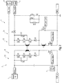
- Fig. 2 a more detailed second embodiment of the inventive emergency lighting driver 1 is shown.
- the construction of the bi-directional flyback converter 2 is shown on a circuit level, while further components are shown as function blocks.
- the individual function blocks will be shown on a circuit level.
- the bi-directional flyback converter 2 comprises a primary side 21 and a secondary side 22.
- the primary side 21 is connected to a mains power supply 3 and to a flyback controller 6.
- the primary side 21 comprises a primary side winding L1 13 of a transformer L1, connected in series to a primary side flyback switch M1.
- the series connection of the primary side winding L1 13 of the transformer L1 and the flyback switch M1 are connected between the mains power supply 3 and ground.
- a primary side snubber 23 In parallel to the primary side winding L1 13 of the transformer L1 is a primary side snubber 23, which consists of a series connection of a diode D1 and three resistors R1, R2 and R3. In parallel to the resistors R2 and R3, the primary side snubber 23 moreover comprises a capacitor C1. The primary side snubber 23 removes undesirable isolations on the primary side.
- the secondary side 22 is connected to a battery switch 4 and to a charge connector 5.
- the secondary side 22 comprises a secondary side winding L1 89 of the transformer L1 and an auxiliary secondary side winding L1 45 connected in series. Moreover, connected in series is a secondary side flyback switch M2.
- the series connection of the secondary side winding L1 89 and the secondary side auxiliary winding L1 45 and the secondary side flyback switch are connected between the battery switch 4 and ground.
- a connecting node between the secondary side winding L1 89 and the secondary side auxiliary winding L1 45 is connected to a secondary side auxiliary winding bypass switch M3, which is connected to ground on its other side.
- the secondary side 22 moreover comprises a secondary side snubber 24 connected in parallel to the secondary side winding of the transformer L1.
- the secondary side snubber 24 consists of a series connection of a diode D2 and three resistors R4, R5 and R6. Connected in parallel to the resistors R5 and R6 is a capacitor C2.
- the secondary side snubber removes undesirable isolations on the secondary side 22.
- the battery switch 4 side connection of the secondary side winding L1 89 of the transformer L1 is moreover connected to a Schottky-diode D3, which connects it to the charge connector 5.
- the Schiottky-diode D3 operates as a rectifier diode.
- the mains power supply 3 provides a rectified mains signal to the primary side 21.
- the flyback controller 6 controls the flyback switch M1 in order to periodically draw power from the mains power supply 3 and store it in the primary side winding L1 13 of the transformer L1.
- the secondary side auxiliary winding flyback switch M2 remains open, while the secondary side auxiliary winding bypass switch M3 remains closed. This bypasses the auxiliary side secondary winding L1 45 of the transformer L1.
- the energy is transferred from the primary side winding L1 13 to the secondary side winding L1 89 of the transformer L1 and provide it to optionally connected lighting means via the diode D3. Additionally, via the same connection, the charge connector 5 connected to a battery charger 7 is provided with energy.
- the battery switch 4 remains open, preventing a direct connection of the battery 10 to the secondary side 22. This prevents the battery 10 from being over-charged and thereby destroyed.
- Fig. 6 is the integrated DALI power supply 9, which is connected to an auxiliary primary side winding L1 67 of the transformer L1. Either this integrated DALI power supply or a further DALI power supply, supply a connected DALI bus during the non-emergency state.
- the mains power supply 3 no longer provides power to the emergency lighting driver 2.
- the battery switch 4 is closed, resulting in a direct connection of a connected battery 10 to the secondary side 22 of the emergency lighting driver 2.
- the secondary side auxiliary winding bypass switch M3 is opened, while the secondary side auxiliary winding flyback switch M2 is operated repeatedly, resulting in a reversed direction flyback converter operation.
- the primary side flyback switch M1 is opened, so that no energy loss towards the mains power supply 3 can occur. Due to the flyback operation of the secondary side auxiliary winding flyback switch M2, energy is repeatedly stored in the secondary side auxiliary winding L1 45 . This energy is transferred to a primary side auxiliary winding L1 67 and then transferred to the integrated DALI power supply 9. This is shown in further detail in Fig. 6 .
- the switches on the primary side 21, especially the flyback switch M1 is controlled by a separate controller from a controller controlling the switches on the secondary side, especially the switches M2, M3, resulting in a proper galvanic separation between the primary side 21 and the secondary side 22.
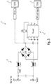
- Fig. 3 details of a third embodiment of the inventive emergency lighting driver 1 are shown. Here, especially details of the mains power supply 3 and the flyback controller 6, which is a primary side controller, are shown.
- the bi-directional flyback converter 2 is connected to a mains power supply 3.
- the mains power supply 3 consists of a mains connection connected to a parallel capacitor, a serial resistor 120R and serial fuses. Moreover, the mains power supply 3 comprises a number of rectifier diodes and a smoothing capacitor.
- the mains power supply 3 is provided with an AC mains voltage and rectifies and smooths this AC voltage to a mains DC voltage. This mains DC voltage is provided to the bi-directional flyback converter 2 and to the flyback controller 6, which again is connected to the primary side flyback switch M1 of the bi-directional flyback converter 2.
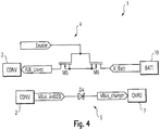
- Fig. 4 details of a fourth embodiment of the inventive emergency lighting driver 1 are shown. Especially here, the battery switch 4 and the charge connector 5 are shown in detail.
- the battery switch 4 is connected between the bi-directional flyback converter 2 and a battery 10.
- the battery switch 4 comprises two serially connected transistors M5, M6, which are activated by an enable signal.
- the battery switch 4 is adapted to connect the secondary side 22 of the bi-directional flyback converter 2 to the battery 10 in the emergency state, and disconnect the same during the non-emergency state, when triggered by the enable signal. This signal is advantageously provided by a controller not displayed here.
- the charge connector 5 is connected between the secondary side of the bi-directional flyback converter 2 and a battery charger 7.
- the charge connector 5 comprises a Schottky-diode D4, which assures that energy is only transferred from the secondary side of the bi-directional flyback converter 2 to the battery charger 7 but not in the reverse direction.
- a threshold may be implemented, which needs to be surpassed for energy to be transferred from the secondary side 22 to the battery charger 7. Such a threshold could be implemented by measuring the voltage at the battery charger side, using for example an ADC input channel of a microcontroller. Also a determination if mains voltage is present or not can be performed in this manner..
- Fig. 5 a further detail of a fifth embodiment of the inventive emergency lighting driver 1 is shown.
- the battery charger 7 is displayed. It is connected to the charge connector 5 and through the charge connector 5 to the secondary side 22 of the bi-directional flyback converter 2.
- the battery charger 7 receives energy from secondary side 22 of the bi-directional flyback converter 2 in the non-emergency state and charges the battery 10 using this energy. In order to do so, it generates a charging signal, which is then provided to the battery 10. This assures that the battery is not over-charged or otherwise destroyed.
- the battery charger 7 is a conventional battery charger, therefore, further elaborations regarding details of its construction are omitted here.
- the battery 10 is moreover connected to the battery switch 4, through which it can be directly connected to the secondary side 22 of the bi-directional flyback converter 2, bypassing the battery charger 7. This is done during the emergency state. During the emergency state, the battery voltage is therefore directly applied to the secondary side 22 of the bi-directional flyback converter 2.
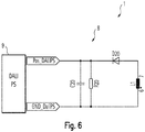
- a further detail of a sixth embodiment of the inventive emergency lighting driver 1 is shown.
- a power supply rectifier 8 connected to the integrated DALI power supply 9 is shown.
- the power supply rectifier 8 consists of a rectifying diode D20 connected in series to a primary side auxiliary winding L1 67 of the transformer L1, and a capacitor C20 and a resistor R20, connected in parallel to the series connection of the primary side auxiliary winding L1 67 and the rectifying diode D20. Together, the rectifying diode D20, the capacitor C20 and the resistor R20 form the power supply rectifier 8.
- Fig. 7 a further detail of an embodiment of the inventive emergency lighting driver 1 is shown.
- the integrated DALI power supply 9 is shown on a circuit level.
- the integrated DALI power supply is connected to the power supply rectifier 8.
- the integrated DALI power supply 9 is a conventional DALI bus power supply, generating a stable supply for the DALI bus from a DC voltage provided by the power supply rectifier 8. Therefore, further elaborations regarding the detailed construction of the integrated DALI power supply 9 are omitted here.
- the invention is not limited to the examples and especially not to the DALI standard.
- the characteristics of the exemplary embodiments can be used in any advantageous combination.
Landscapes
- Dc-Dc Converters (AREA)
- Circuit Arrangement For Electric Light Sources In General (AREA)
Priority Applications (3)
| Application Number | Priority Date | Filing Date | Title |
|---|---|---|---|
| EP19203202.7A EP3809557A1 (fr) | 2019-10-15 | 2019-10-15 | Dispositif d'éclairage d'urgence bidirectionnel |
| PCT/EP2020/079002 WO2021074276A1 (fr) | 2019-10-15 | 2020-10-15 | Dispositif d'éclairage d'urgence |
| EP20788836.3A EP4022738A1 (fr) | 2019-10-15 | 2020-10-15 | Dispositif d'éclairage d'urgence |
Applications Claiming Priority (1)
| Application Number | Priority Date | Filing Date | Title |
|---|---|---|---|
| EP19203202.7A EP3809557A1 (fr) | 2019-10-15 | 2019-10-15 | Dispositif d'éclairage d'urgence bidirectionnel |
Publications (1)
| Publication Number | Publication Date |
|---|---|
| EP3809557A1 true EP3809557A1 (fr) | 2021-04-21 |
Family
ID=68281011
Family Applications (2)
| Application Number | Title | Priority Date | Filing Date |
|---|---|---|---|
| EP19203202.7A Withdrawn EP3809557A1 (fr) | 2019-10-15 | 2019-10-15 | Dispositif d'éclairage d'urgence bidirectionnel |
| EP20788836.3A Pending EP4022738A1 (fr) | 2019-10-15 | 2020-10-15 | Dispositif d'éclairage d'urgence |
Family Applications After (1)
| Application Number | Title | Priority Date | Filing Date |
|---|---|---|---|
| EP20788836.3A Pending EP4022738A1 (fr) | 2019-10-15 | 2020-10-15 | Dispositif d'éclairage d'urgence |
Country Status (2)
| Country | Link |
|---|---|
| EP (2) | EP3809557A1 (fr) |
| WO (1) | WO2021074276A1 (fr) |
Families Citing this family (1)
| Publication number | Priority date | Publication date | Assignee | Title |
|---|---|---|---|---|
| EP4586459A1 (fr) * | 2024-01-11 | 2025-07-16 | Tridonic GmbH & Co. KG | Unité d'alimentation électrique de secours, psu, pour un bus de commande d'éclairage |
Citations (5)
| Publication number | Priority date | Publication date | Assignee | Title |
|---|---|---|---|---|
| US6876159B1 (en) * | 2003-11-28 | 2005-04-05 | Fego Precision Industrial Co, Ltd. | Electronic ballast system for emergency lighting applications |
| US20080197790A1 (en) * | 2002-12-11 | 2008-08-21 | Mangiaracina Anthony A | Lighting utilizing power over the ethernet |
| US20130147351A1 (en) * | 2011-12-12 | 2013-06-13 | John J. Trainor | Dimming control for emergency lighting systems |
| WO2018234019A1 (fr) * | 2017-06-19 | 2018-12-27 | Tridonic Gmbh & Co Kg | Circuit d'attaque pour éclairage d'urgence |
| WO2019166328A1 (fr) | 2018-02-28 | 2019-09-06 | Tridonic Gmbh & Co Kg | Pilote de del de secours avec commutateur de test combiné, indicateur d'état et opération de sélection de durée |
Family Cites Families (1)
| Publication number | Priority date | Publication date | Assignee | Title |
|---|---|---|---|---|
| DE102012214832B4 (de) * | 2012-08-21 | 2024-11-28 | Tridonic Uk Ltd. | Notlichtgerät mit Potentialtrennung zwischen Leuchtmittel und Energiespeicher |
-
2019
- 2019-10-15 EP EP19203202.7A patent/EP3809557A1/fr not_active Withdrawn
-
2020
- 2020-10-15 EP EP20788836.3A patent/EP4022738A1/fr active Pending
- 2020-10-15 WO PCT/EP2020/079002 patent/WO2021074276A1/fr not_active Ceased
Patent Citations (5)
| Publication number | Priority date | Publication date | Assignee | Title |
|---|---|---|---|---|
| US20080197790A1 (en) * | 2002-12-11 | 2008-08-21 | Mangiaracina Anthony A | Lighting utilizing power over the ethernet |
| US6876159B1 (en) * | 2003-11-28 | 2005-04-05 | Fego Precision Industrial Co, Ltd. | Electronic ballast system for emergency lighting applications |
| US20130147351A1 (en) * | 2011-12-12 | 2013-06-13 | John J. Trainor | Dimming control for emergency lighting systems |
| WO2018234019A1 (fr) * | 2017-06-19 | 2018-12-27 | Tridonic Gmbh & Co Kg | Circuit d'attaque pour éclairage d'urgence |
| WO2019166328A1 (fr) | 2018-02-28 | 2019-09-06 | Tridonic Gmbh & Co Kg | Pilote de del de secours avec commutateur de test combiné, indicateur d'état et opération de sélection de durée |
Non-Patent Citations (1)
| Title |
|---|
| WU Y-C ET AL: "A compact single-stage converter for emergency lighting applications", POWER ELECTRONICS SPECIALISTS CONFERENCE; [ANNUAL POWER ELECTRONICS SPECIALISTS CONFERENCE],, vol. 2, 23 June 2002 (2002-06-23), pages 779 - 784, XP010747502, ISBN: 978-0-7803-7262-7 * |
Also Published As
| Publication number | Publication date |
|---|---|
| EP4022738A1 (fr) | 2022-07-06 |
| WO2021074276A1 (fr) | 2021-04-22 |
Similar Documents
| Publication | Publication Date | Title |
|---|---|---|
| US10903682B2 (en) | Power over ethernet emergency lighting system and method of detecting power loss of a link segment thereof | |
| EP2823690B1 (fr) | Système d'alimentation électrique d'unité de lampe | |
| US5241217A (en) | UPS with input commutation between AC and DC sources of power | |
| US8716987B2 (en) | Electrical power supply arrangement and use thereof | |
| US5726849A (en) | Input overcurrent suppression circuit | |
| US7256556B2 (en) | Equipment and methods for emergency lighting that provides brownout detection and protection | |
| KR102565896B1 (ko) | 전기 또는 하이브리드 차량용 전기 충전 시스템 | |
| US8130524B2 (en) | Bi-directional DC to DC power converter having a neutral terminal | |
| EP2823691B1 (fr) | Source de lumière à led | |
| US9917522B2 (en) | Power control apparatus for sub-module of MMC converter | |
| CN108684107B (zh) | 复式隔离型的led应急灯控制电路 | |
| WO2012043249A1 (fr) | Système de décharge et véhicule électrique | |
| US10749340B2 (en) | Power switch with power harvesting for local controller | |
| KR20220072873A (ko) | 차량 전기 시스템 | |
| US11714472B2 (en) | Power over ethernet emergency lighting system and method of detecting power loss of a link segment thereof | |
| EP3809557A1 (fr) | Dispositif d'éclairage d'urgence bidirectionnel | |
| CN113942404A (zh) | 充放电系统、车辆以及交直流电源选择电路 | |
| HK1257374A1 (zh) | 用於照明设备的应急电源 | |
| EP0892486A1 (fr) | Alimentation en courant électrique avec sortie reconfigurable pour tensions de sortie différentes et procédé pour sa mise en oeuvre | |
| KR102047826B1 (ko) | 과전압 보호 회로 및 이를 포함하는 전원 공급 장치 | |
| KR101052310B1 (ko) | 다운라이트용 비상등 | |
| JP7208588B2 (ja) | 電源装置および誘導灯 | |
| JPS58139675A (ja) | 電力変換装置 | |
| KR102620824B1 (ko) | 컨버터 시스템 및 양방향 컨버터를 이용하는 전력 변환 방법 | |
| JPH07147772A (ja) | 電源装置 |
Legal Events
| Date | Code | Title | Description |
|---|---|---|---|
| PUAI | Public reference made under article 153(3) epc to a published international application that has entered the european phase |
Free format text: ORIGINAL CODE: 0009012 |
|
| STAA | Information on the status of an ep patent application or granted ep patent |
Free format text: STATUS: THE APPLICATION HAS BEEN PUBLISHED |
|
| AK | Designated contracting states |
Kind code of ref document: A1 Designated state(s): AL AT BE BG CH CY CZ DE DK EE ES FI FR GB GR HR HU IE IS IT LI LT LU LV MC MK MT NL NO PL PT RO RS SE SI SK SM TR |
|
| AX | Request for extension of the european patent |
Extension state: BA ME |
|
| STAA | Information on the status of an ep patent application or granted ep patent |
Free format text: STATUS: THE APPLICATION IS DEEMED TO BE WITHDRAWN |
|
| 18D | Application deemed to be withdrawn |
Effective date: 20211022 |