EP3809934B1 - Reinigungsvorrichtung - Google Patents
Reinigungsvorrichtung Download PDFInfo
- Publication number
- EP3809934B1 EP3809934B1 EP19811434.0A EP19811434A EP3809934B1 EP 3809934 B1 EP3809934 B1 EP 3809934B1 EP 19811434 A EP19811434 A EP 19811434A EP 3809934 B1 EP3809934 B1 EP 3809934B1
- Authority
- EP
- European Patent Office
- Prior art keywords
- housing
- hole
- center
- gravity
- partition
- Prior art date
- Legal status (The legal status is an assumption and is not a legal conclusion. Google has not performed a legal analysis and makes no representation as to the accuracy of the status listed.)
- Active
Links
Images



Classifications
-
- A—HUMAN NECESSITIES
- A47—FURNITURE; DOMESTIC ARTICLES OR APPLIANCES; COFFEE MILLS; SPICE MILLS; SUCTION CLEANERS IN GENERAL
- A47L—DOMESTIC WASHING OR CLEANING; SUCTION CLEANERS IN GENERAL
- A47L9/00—Details or accessories of suction cleaners, e.g. mechanical means for controlling the suction or for effecting pulsating action; Storing devices specially adapted to suction cleaners or parts thereof; Carrying-vehicles specially adapted for suction cleaners
- A47L9/10—Filters; Dust separators; Dust removal; Automatic exchange of filters
- A47L9/16—Arrangement or disposition of cyclones or other devices with centrifugal action
- A47L9/1616—Multiple arrangement thereof
- A47L9/1625—Multiple arrangement thereof for series flow
- A47L9/1633—Concentric cyclones
-
- A—HUMAN NECESSITIES
- A47—FURNITURE; DOMESTIC ARTICLES OR APPLIANCES; COFFEE MILLS; SPICE MILLS; SUCTION CLEANERS IN GENERAL
- A47L—DOMESTIC WASHING OR CLEANING; SUCTION CLEANERS IN GENERAL
- A47L5/00—Structural features of suction cleaners
- A47L5/12—Structural features of suction cleaners with power-driven air-pumps or air-compressors, e.g. driven by motor vehicle engine vacuum
- A47L5/22—Structural features of suction cleaners with power-driven air-pumps or air-compressors, e.g. driven by motor vehicle engine vacuum with rotary fans
- A47L5/24—Hand-supported suction cleaners
-
- A—HUMAN NECESSITIES
- A47—FURNITURE; DOMESTIC ARTICLES OR APPLIANCES; COFFEE MILLS; SPICE MILLS; SUCTION CLEANERS IN GENERAL
- A47L—DOMESTIC WASHING OR CLEANING; SUCTION CLEANERS IN GENERAL
- A47L9/00—Details or accessories of suction cleaners, e.g. mechanical means for controlling the suction or for effecting pulsating action; Storing devices specially adapted to suction cleaners or parts thereof; Carrying-vehicles specially adapted for suction cleaners
- A47L9/10—Filters; Dust separators; Dust removal; Automatic exchange of filters
- A47L9/16—Arrangement or disposition of cyclones or other devices with centrifugal action
-
- A—HUMAN NECESSITIES
- A47—FURNITURE; DOMESTIC ARTICLES OR APPLIANCES; COFFEE MILLS; SPICE MILLS; SUCTION CLEANERS IN GENERAL
- A47L—DOMESTIC WASHING OR CLEANING; SUCTION CLEANERS IN GENERAL
- A47L9/00—Details or accessories of suction cleaners, e.g. mechanical means for controlling the suction or for effecting pulsating action; Storing devices specially adapted to suction cleaners or parts thereof; Carrying-vehicles specially adapted for suction cleaners
- A47L9/10—Filters; Dust separators; Dust removal; Automatic exchange of filters
- A47L9/16—Arrangement or disposition of cyclones or other devices with centrifugal action
- A47L9/1608—Cyclonic chamber constructions
-
- A—HUMAN NECESSITIES
- A47—FURNITURE; DOMESTIC ARTICLES OR APPLIANCES; COFFEE MILLS; SPICE MILLS; SUCTION CLEANERS IN GENERAL
- A47L—DOMESTIC WASHING OR CLEANING; SUCTION CLEANERS IN GENERAL
- A47L9/00—Details or accessories of suction cleaners, e.g. mechanical means for controlling the suction or for effecting pulsating action; Storing devices specially adapted to suction cleaners or parts thereof; Carrying-vehicles specially adapted for suction cleaners
- A47L9/10—Filters; Dust separators; Dust removal; Automatic exchange of filters
- A47L9/16—Arrangement or disposition of cyclones or other devices with centrifugal action
- A47L9/1616—Multiple arrangement thereof
- A47L9/1641—Multiple arrangement thereof for parallel flow
-
- A—HUMAN NECESSITIES
- A47—FURNITURE; DOMESTIC ARTICLES OR APPLIANCES; COFFEE MILLS; SPICE MILLS; SUCTION CLEANERS IN GENERAL
- A47L—DOMESTIC WASHING OR CLEANING; SUCTION CLEANERS IN GENERAL
- A47L9/00—Details or accessories of suction cleaners, e.g. mechanical means for controlling the suction or for effecting pulsating action; Storing devices specially adapted to suction cleaners or parts thereof; Carrying-vehicles specially adapted for suction cleaners
- A47L9/10—Filters; Dust separators; Dust removal; Automatic exchange of filters
- A47L9/16—Arrangement or disposition of cyclones or other devices with centrifugal action
- A47L9/165—Construction of inlets
-
- A—HUMAN NECESSITIES
- A47—FURNITURE; DOMESTIC ARTICLES OR APPLIANCES; COFFEE MILLS; SPICE MILLS; SUCTION CLEANERS IN GENERAL
- A47L—DOMESTIC WASHING OR CLEANING; SUCTION CLEANERS IN GENERAL
- A47L9/00—Details or accessories of suction cleaners, e.g. mechanical means for controlling the suction or for effecting pulsating action; Storing devices specially adapted to suction cleaners or parts thereof; Carrying-vehicles specially adapted for suction cleaners
- A47L9/10—Filters; Dust separators; Dust removal; Automatic exchange of filters
- A47L9/16—Arrangement or disposition of cyclones or other devices with centrifugal action
- A47L9/1658—Construction of outlets
- A47L9/1666—Construction of outlets with filtering means
-
- A—HUMAN NECESSITIES
- A47—FURNITURE; DOMESTIC ARTICLES OR APPLIANCES; COFFEE MILLS; SPICE MILLS; SUCTION CLEANERS IN GENERAL
- A47L—DOMESTIC WASHING OR CLEANING; SUCTION CLEANERS IN GENERAL
- A47L9/00—Details or accessories of suction cleaners, e.g. mechanical means for controlling the suction or for effecting pulsating action; Storing devices specially adapted to suction cleaners or parts thereof; Carrying-vehicles specially adapted for suction cleaners
- A47L9/28—Installation of the electric equipment, e.g. adaptation or attachment to the suction cleaner; Controlling suction cleaners by electric means
- A47L9/2868—Arrangements for power supply of vacuum cleaners or the accessories thereof
- A47L9/2884—Details of arrangements of batteries or their installation
-
- A—HUMAN NECESSITIES
- A47—FURNITURE; DOMESTIC ARTICLES OR APPLIANCES; COFFEE MILLS; SPICE MILLS; SUCTION CLEANERS IN GENERAL
- A47L—DOMESTIC WASHING OR CLEANING; SUCTION CLEANERS IN GENERAL
- A47L9/00—Details or accessories of suction cleaners, e.g. mechanical means for controlling the suction or for effecting pulsating action; Storing devices specially adapted to suction cleaners or parts thereof; Carrying-vehicles specially adapted for suction cleaners
- A47L9/32—Handles
- A47L9/322—Handles for hand-supported suction cleaners
Definitions
- the present invention relates to a cleaning appliance.
- a cleaning appliance is an appliance for cleaning the indoor by sucking particles such as dust. It is general that a conventional cleaning appliance comprises a housing provided with an intake unit and an exhaust unit, a fan for moving the air entering the intake unit to the exhaust unit, a separator for separating particles from the air moving by the fan, a battery for supplying a power to the fan, and a handle provided in the housing.
- the conventional cleaning apparatus has a problem in that the center of gravity of the appliance is formed at a position far away from the handle because the intake unit is provided on a front surface of the housing, the handle is provided on a rear surface of the housing and the separator and the fan, which are heavy parts, are provided inside the housing.
- the case that the center of gravity of the cleaning appliance is far away from the handle means that the center of gravity of the cleaning appliance is far away from a user's wrist, and if the center of gravity of the cleaning appliance is far away from a user's wrist, a problem occurs in that a big force is required for direction switching or position change of the cleaning appliance.
- the fan provided in the conventional cleaning appliance is generally provided to discharge the air toward the handle.
- the air since the air is discharged to the user's hands which are gripping the handle, a problem occurs in that displeasure is caused to the user.
- CN 206 576 819 U relates to a hand-held vacuum cleaner mainly comprises a main body and a vacuuming accessory connected thereto, the main body comprising a fuselage, a dust bucket connected to the fuselage, and a main suction pipe connected to the front side of the dust bucket and a handle connected to the rear side of the fuselage, the fuselage is connected with a cyclone cone assembly, and an air inlet filter assembly is arranged above the cyclone cone assembly.
- the rear side of the air filter assembly is provided with an air outlet filter assembly, a battery pack is accommodated in the fuselage, and a motor is arranged between the air inlet filter assembly and the air outlet filter assembly, so that it is located on the upper rear side of the main body.
- the cyclone cone assembly is detachably connected to the fuselage and includes a cyclone cone and a mesh filter wherein the mesh filter is located on the periphery of the cyclone cone.
- An object of the present invention is to provide a cleaning appliance of which handling is easy.
- Another object of the present invention is to provide a cleaning appliance which is capable of preventing the air from being discharged toward a user's hands.
- the present invention provides a cleaning appliance comprising a first housing provided in a hollow cylinder shape: a second housing fixed to a circumferential surface of the first housing along a longitudinal direction of the first housing and provided with an intake unit through which the air enters; a third housing provided on a circumferential surface of the first housing along the longitudinal direction of the first housing and provided with an exhaust hole; a first communication hole for communicating the first housing with the second housing; a second communication hole for communicating the first housing with the third housing; a fan provided to include an impeller located in the third housing, a rotary shaft to which the impeller is fixed, and a motor rotating the rotary shaft, moving the air supplied from the second communication hole to the exhaust hole; a particle separator provided inside the first housing to provide a path for guiding the air entering the first communication hole to the second communication hole, separating particles from the air by using a centrifugal force; a battery housing protruded from a rear surface of the first housing located in a direction opposite to a position of the intake unit toward
- the center of gravity of the fan may be located above the first reference line, and the center of gravity of the battery may be located below the first reference line.
- the center of gravity of the handle may be located between the first reference line and a second reference line passing through the center of gravity of the fan along the longitudinal direction of the first housing.
- the center of gravity of the fan, the center of gravity of the particle separator, the center of gravity of the battery, and the center of gravity of the handle may all be located on a single plane that includes the first reference line and the second reference line.
- the handle may include a first handle body extended from the rear surface of the third housing along a longitudinal direction of the rotary shaft, providing a space for grip of a user, and a second handle body provided to connect a free end of the first handle body with an upper surface of the battery housing, providing a space for grip of a user.
- a connection point of the first handle body and the second handle body may be located between the first reference line and the second reference line.
- the first handle body may be inclined from the rear surface of the third housing toward the battery housing, and the second handle body may be inclined toward the rear surface of the third housing.
- the particle separator may include a partition for partitioning an inner space of the first housing into a front space communicated with the first communication hole and a rear space communicated with the second communication hole, a partition through hole provided to pass through the partition, chamber bodies provided in a hollow cylinder shape, having one end fixed to the partition and the other end which is in contact with the front surface of the first housing, and partitioning the front space into a first chamber communicated with the first communication hole and a second chamber communicated with the partition through hole, a body partition partitioning an inner space of the second chamber into a first space communicated with the partition through hole and a second space which is not communicated with the partition through hole, a through hole provided to pass through the chamber bodies to communicate the first space with the first chamber, a path body provided in a pipe surrounding the partition through hole, having one end fixed to the partition and the other end communicated with the second space by passing through the body partition, a discharge pipe provided as a pipe extended from the partition through hole toward the body partition and provided inside the path body, an inlet provided to
- the fan may include a case provided in the third housing, storing the impeller therein, a case intake unit provided on one surface of the case headed for a rear surface of the third housing to allow the air to enter the inside of the case, and a case exhaust hole provided on one surface of the case headed for a front surface of the third housing to discharge the air inside the case to the outside, and the rotary shaft may be located on a straight line passing through the center of the case intake unit and the center of the case exhaust hole.
- the cleaning appliance of the present invention may further comprise a first filter located between the second communication hole and the case intake unit, filtering the air, and a second filter located between the case exhaust hole and the exhaust hole to filter the air, wherein the second filter is provided to filter particles smaller than those filtered by the first filter.
- the cleaning appliance of the present invention may further comprise a first filter located between the partition through hole and the second communication hole, filtering particles, and a second filter located between the case exhaust hole and the exhaust hole to filter particles, wherein the second filter is provided to filter particles smaller than those filtered by the first filter.
- the present invention may provide a cleaning appliance that improves a user's convenience (handling) by decentering the center of gravity of components constituting the cleaning appliance based on a user's wrist.
- the present invention may provide a cleaning appliance which is capable of preventing the air from being discharged toward a user's hands.
- FIG. 1 illustrates an example of a cleaning appliance 100 of the present invention.
- the cleaning appliance of the present invention comprises a housing 1 provided with a plurality of spaces 11, 12 and 15 partitioned from one another, an intake hole 131 for allowing the air to enter the housing 1, an exhaust hole 163 for allowing the air inside the housing 1 toward the outside of the housing 1, a fan 5 provided inside the housing 1, discharging the air inside the housing 1 toward the exhaust hole 163, a particle separator 4 for guiding the air entering the intake hole 131 to the fan 5 and separating particles from the air by using a centrifugal force, and a handle 8 provided in the housing 1 to allow a user to grip it.
- the handle 7 may be provided to be located at a point (spaced point of 180°) symmetrical to a point, in which the intake unit 11 is located, in a space provided by a circumferential surface of the housing 1.
- the housing 1 may be provided in a hollow cylinder shape.
- the housing 1 includes a first housing 11 providing a space in which the particle separator 4 is stored, a second housing 13 fixed to a circumferential surface of the first housing 11 and provided with the intake hole 131, and a third housing 15 fixed to a circumferential surface of the first housing 11 and provided with the fan and the exhaust hole 163.
- the second housing 13 and the third housing 15 may be provided along a longitudinal direction of the first housing 11. That is, a horizontal line passing through the center of the second housing 13 may be fixed to the circumferential surface of the first housing 11 to be parallel with a horizontal line passing through the center of the first housing 11, and a horizontal line passing through the center of the third housing 15 may also be fixed to the circumferential surface of the first housing 11 to be parallel with the horizontal line passing through the center of the first housing 11.
- the horizontal line passing through the center of the first housing is parallel with the horizontal line passing through the center of the second housing 11 or the third housing means that a straight line passing through the center of the first housing is provided so as not to meet a straight line passing through the center of the second housing or the third housing.
- the second housing 13 and the third housing 15 may be fixed to the first housing 11 such that the horizontal line passing through the center of the second housing 13 is matched with the horizontal line passing through the center of the third housing 15.
- the first housing 11 is communicated with the second housing 13 through a first communication hole 17, and is communicated with the third housing 15 through a second communication hole 19.
- the air entering the intake hole 131 moves to the first housing 11 through the first communication hole 17, and the air inside the first housing 11 moves to the third housing 15 through the second communication hole 19.
- a first housing discharge hole 111 opened or closed by a first cover 12 is provided on a front surface (point spaced apart from the point, in which the handle is located, as much as 180°, one surface of the first housing toward a direction where the intake hole is located) of the first housing 11.
- the first cover 12 may rotatably be provided in the first housing 11.
- a shaft 112 forming a rotation center of the first cover and a fastening unit 113 provided to face the shaft 112 may be provided on the circumferential surface of the first housing 11, and a first cover body 121 coupled to the shaft 112 and a cover fastening unit 125 provided on a free end of the first cover body 121 and detachably coupled to the fastening unit 113 may be provided in the first cover 12.
- a sealing portion 127 compressed between the first housing 11 and the first cover body 121 when the first housing discharge hole 111 is closed may further be provided in the first cover 12.
- the sealing portion 127 is made of an elastic body such as rubber.
- a third housing discharge hole 151 opened or closed by a second cover 16 may be provided on a circumferential surface of the third housing 15.
- the third housing discharge hole 151 may be provided to pass through a surface, which is parallel with the circumferential surface of the first housing 11, in a space provided by the third housing 15.
- the third housing discharge hole 151 may be provided in a space, which is located in a direction (Z-axis direction) orthogonal to a longitudinal direction (Y-axis direction) of the handle 8, in the space provided by the third housing 15.
- the second cover 16 is provided with a second cover body 161 for opening or closing the third housing discharge hole 151, wherein the second cover body 161 may be provided to form the circumferential surface of the third housing 15 when the third housing discharge hole 151 is closed.
- the exhaust hole 163 may be provided with a plurality of holes passing through the second cover body 161.
- the fan 5 is a means provided in the third housing 15, moving the air inside the housing 1 to the exhaust hole 163, and the particle separator 4 is a means provided in the first housing 11, providing a path for guiding the air entering the first housing 11 through the first communication hole 17 to the second communication hole 19. Particles such as dust contained in the air are separated from the air by a centrifugal force while the particle separator 4 is moving to the fan 5 along the path.
- a detailed structure of the particle separator is as follows.
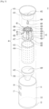
- the particle separator 4 includes a chamber forming portion 41 for forming a first chamber 41a and a second chamber 41b inside the first housing 1, and a cyclone forming portion 42 for forming an air current arousing a centrifugal force while supplying the air inside the second chamber 41b to the fan 5.
- the chamber forming portion 41 may include a partition 411 for partitioning an inner space of the first housing 1 into a front space F communicated with the first communication hole 17 and a rear space R communicated with the second communication hole 19, a partition through hole 412 provided to pass through the partition 411, chamber bodies 413 and 415 provided as a cylinder having one end fixed to the partition 411 and the other end which is in contact with the first cover 12, partitioning the front space R into two chambers 41a and 41b, and a body partition 417 for partitioning the second chamber 41b formed inside the chamber body 415 into a first space 418 and a second space 419.
- the chamber bodies may be provided as a first body 413 fixed to the partition 411 and a second body 415 fixed to the first body.
- the partition through hole 412 communicates the second chamber 41b with the rear space R of the first housing. That is, the first body 413 should be provided in a shape surrounding the partition through hole 412.
- the first body 413 and the second body 415 may be provided in a hollow cylinder shape, and the second body 415 may be provided such that its one end is fixed to a free end of the first body 413 and its other end is in contact with the sealing portion 127 of the first cover.
- a plurality of body through holes 414 for communicating the first chamber 41a with the first space 418 are provided on a circumferential surface of the first body 413. Therefore, the air entering the first chamber 41a through the intake hole 131 and the first communication hole 17 may be supplied to the first space 418 of the second chamber 41b through the body through holes 414.
- the body partition 417 is fixed to any one of the first body 413 and the second body 415 to partition the inside of the second chamber 41b into two spaces 418 and 419.
- the first space 418 is a space communicated with the partition through hole 412
- the second space 419 is a space which is not communicated with the partition through hole 412.
- a body discharge hole 416 (see FIG. 3 ) opened or closed by the first cover body 121 is provided on the bottom of the second body 415. Therefore, if the first cover body 121 opens the first housing discharge hole 111, the body discharge hole 416 will be opened.
- the cyclone forming portion 42 may include a path body 421 of which one end is fixed to the partition 411 and the other end is communicated with the second space 419 by passing through the body partition 417, a discharge pipe 424 located inside the path body 421 and communicated with the partition through hole 412, an inlet 423 provided to pass through a circumferential surface of the path body 421, and an air flow forming portion 425 provided between an outer circumferential surface of the discharge pipe 424 and an inner circumferential surface of the path body.
- the path body 421 is provided as a pipe surrounding the partition through hole 412, and the discharge pipe 424 is located inside the path body 421.
- the path body 421 is communicated with the second space 419 through a particle discharge hole 422 provided at one end (one end of the path body which is not fixed to the partition).
- the path body 421 may be provided to have a diameter which becomes smaller toward a free end. This is to strongly maintain intensity of the air flow.
- the air flow forming portion 425 is provided in a screw shape, and the inlet 423 is located to be higher than the air flow forming portion 425. Therefore, the air entering the path body 421 through the inlet 423 when the fan 5 is operated will move (cyclone movement) to be rotated inside the path body 421 in the middle of moving to the discharge pipe 424 through the air flow forming portion 425.
- the particles contained in the air move to a rim (the circumferential surface of the path body) of the path by means of a centrifugal force and then remain in the path body 421 by means of gravity, and the air will be discharged to the rear space R through the discharge pipe 424.
- the inlet 423 may be provided as a hole provided to pass through an upper surface of the path body 421.
- an upper end of the path body 421 should be provided to be spaced apart from the partition 411 without being fixed to the partition 411. Since the path body 421 is fixed to the partition 411 through the air flow forming portion 425 and the discharge pipe 424, the path body 421 may maintain a state fixed to the partition 411 even though the upper end of the path body 421 is spaced apart from the partition 411.
- the cyclone forming portion 42 having the aforementioned structure may be provided with a plurality of cyclone forming portions.
- FIG. 3 illustrates an example of a particle separator 4 provided with nine cyclone forming portions 42.
- the fan 5 may include a case 51 provided in the third housing 15, an impeller 57 rotatably provided inside the case, and a motor 54 fixed to the case, rotating the impeller 57.
- the case 51 is provided with a case intake hole 511 and a case exhaust hole 513, wherein the case intake hole 511 is a means for allowing the air discharged from the second communication hole 19 to enter the case 51, and the case exhaust hole 513 is a means for allowing the air inside the case 51 to be discharged to the discharge hole 163.
- the case intake hole 511 and the case exhaust hole 513 which are capable of performing the aforementioned function, may be located anywhere in a space provided by the case 51.
- FIG. 2 illustrates an example of a case that the case intake hole 511 is provided to pass through one surface of the case 51 headed for a rear surface (surface to which a handle is fixed) of the third housing 15 and the case exhaust hole 513 is provided to pass through one surface of the case 51 headed for a front surface of the third housing 15.
- the motor 54 is fixed to a support 515 provided in the case 51.
- FIG. 2 illustrates an example of a case that the support 515 is located between the case intake hole 511 and the case exhaust hole 513 and a rotary shaft 545 is connected to the impeller 57 by passing through the support 515.
- the motor 54 may include a fixed unit 541 fixed to the support 515, a stator 543 provided inside the fixed unit, and a permanent magnet 546 fixed to a free end (one of a rotary shaft located inside the fixed unit) of the rotary shaft 545.
- the rotary shaft 545 may be located on a straight line passing through the center of the case intake hole 511 and the center of the case exhaust hole 513.
- the present invention may further include at least one of a first filter 91 and a second filter 92.
- FIG. 2 illustrates an example of a case that the first filter 91 and the second filter 92 are provided in the cleaning appliance 100 of the present invention.
- the first filter 91 may be located between the second communication hole 19 and the case intake hole 511 and provided to filter the air
- the second filter 92 may be located between the case exhaust hole 513 and the exhaust hole 163 and provided to filter the air.
- the first filter 91 and the second filter 92 may be provided to filter particles having the same size, or may be provided to filter particles having different sizes. In the latter case, it is preferable that the second filter 92 filters particles smaller than those filtered by the first filter 91. This is to minimize the amount of fine dust discharged to an indoor space.
- a user may clean the first filter 91 and the second 92 by detaching them from the third housing 15 when detaching the second cover 16 from the third housing 15.
- the first filter 91 may be located between the partition through hole 412 and the second communication hole 19 to filter the air.
- the first filter 91 is provided to be drawn out of the first housing 11 through the circumferential surface of the first housing 11 and the second filter 92 is provided to detached from the third housing through the third housing discharge hole 151.
- the motor 54 provided in the fan 5 may be provided to be supplied with a power through a power source provided indoor, or may be provided to be supplied with a power through a battery 7 detachably provided in the housing 1.
- the first housing 11 should be provided with a battery housing 6 for storing the battery 7.
- the battery housing 6 may be provided to be protruded from a rear surface (surface opposite to a position of the intake hole) of the first housing 11 toward a direction far away from the intake hole.
- one end of the handle 8 may be fixed to a rear surface (surface opposite to a position of the intake hole) of the third housing 15 and the other end of the handle 8 may be fixed to the battery housing 6.
- the handle 8 may be provided with a first handle body 83 fixed to the rear surface of the third housing 15, and a second handle body 81 connecting a free end of the first handle body 83 with an upper surface of the battery housing 6.
- the first handle body 83 is provided in a bar shape extended to a direction far away from the rear surface of the third housing 15.
- One end of the second handle body 81 may be connected to a free end of the first handle body 83, and the other end of the second handle body 81 may be fixed to an upper surface of the battery housing 6. This is to allow a user to handle the cleaning appliance 100 even by using the first handle body 83 or to handle the cleaning appliance 100 even by using the second handle body 81.
- the first handle body 83 is provided to be inclined from the rear surface of the third housing 15 toward the battery housing 6, and the second handle body 81 is provided to be inclined toward the rear surface of the third housing 15.
- the battery 7 may detachably be coupled to the battery housing 6 through an insertion hole provided to pass through the bottom of the battery housing 6 or a side of the battery housing 6.
- a length (length of Y-axis directional battery) of the battery 7 from the rear surface of the first housing 11 to a direction where the first handle body 83 is located is set to be longer than a length (length of Z-axis directional battery) of the battery 7 with respect to a height direction of the housing 1 and a length (length of X-axis directional battery) of the battery with respect to a diameter direction of the first housing 11.
- the air entering the second chamber 41b moves to the path body 421 through the inlet 423, and the air entering the path body 421 will cyclone move during the process of passing through the air flow forming portion 425.
- the particles contained in the air move to the circumferential surface of the path body 421 by a centrifugal force and then remain in the path body by gravity, and the air will be discharged to the outside of the housing 1 through the discharge pipe 424, the partition through hole 412, the second communication hole 19, the case intake hole 511, the case exhaust hole 513, and the exhaust hole 163.
- the user may remove the particles collected in the second space 419 and the first chamber 41a by opening the first housing discharge hole 11 through the first cover 12.
- the center of gravity G2 of the fan is provided between the center of gravity G1 of the particle separator and the center of gravity G3 of the battery, and the rotary shaft 545 of the fan is provided in parallel with a straight line L1 (first reference line) passing through the center of gravity G1 of the particle separator along a longitudinal direction (Y-axis direction) of the first housing 11.
- the case that the rotary shaft 545 of the fan is provided in parallel with a straight line L1 passing through the center of gravity of the particle separator means that a straight line L2 (second reference line, horizontal line passing through the center of gravity of the fan) passing through the center of the rotary shaft along a longitudinal direction of the rotary shaft 545 does not meet the straight line L1 passing through the center of gravity of the particle separator by being spaced apart from the straight line L1 along a height direction (Z-axis direction) of the housing 1.
- a straight line L2 second reference line, horizontal line passing through the center of gravity of the fan
- the center of gravity of the cleaning apparatus is far away from the handle 8.
- the case that the center of gravity of the cleaning apparatus is far away from the handle 8 means that the center of gravity of the cleaning apparatus is located to be far away from the user's wrist, and if the center of gravity of the cleaning appliance is far away from the user's wrist, a problem occurs in that a big force is required for direction switching or position change of the cleaning appliance.
- the case that the center of gravity G2 of the fan is located between the center of gravity G1 of the particle separator and the center of gravity G3 of the battery becomes a means for solving the problem that a big force is required for manipulation of the cleaning appliance by moving the center of gravity of the cleaning apparatus to a direction close to the handle 8.
- the center of gravity of the cleaning apparatus will be far away from the handle 8. Therefore, the case that the rotary shaft 545 is not located on the straight line L1 passing through the center of gravity of the particle separator becomes a means for solving the problem that a big force is required for manipulation of the cleaning appliance.
- the center of gravity G2 of the fan is located to be higher than the center of gravity G1 of the particle separator, and the center of gravity G1 of the particle separator is located to be higher than the center of gravity G3 of the battery. That is, the center of gravity G2 of the fan may be provided to be located above the straight line L1 passing through the center of gravity of the particle separator and the center of gravity G3 of the battery may be provided to be located below the straight line L1 passing through the center of gravity of the particle separator.
- the center of gravity G4 of the handle may be provided to be located between the straight line L2 passing through the center of gravity G2 of the fan and the straight line passing through the center of gravity G1 of the particle separator.
- a connection point 85 between the first handle body 83 and the second handle body 81 is located between the straight line L2 passing through the rotary shaft 545 and the straight line L1 passing through the center of gravity of the particle separator. This is to allow a user to handle the cleaning apparatus 100 by using a small force through any one of the handle bodies 81 and 83.
- the center of gravity G2 of the fan, the center of gravity G1 of the particle separator, the center of gravity G3 of the battery, and the center of gravity G4 of the handle are provided on a single plane (height directional section of the cleaning apparatus). This is because that the case that the centers of gravities G1, G2, G3 and G4 are all located on a height directional section (Z-axis direction) of the cleaning apparatus is more favorable for handling of the cleaning apparatus.
Landscapes
- Engineering & Computer Science (AREA)
- Mechanical Engineering (AREA)
- Filters For Electric Vacuum Cleaners (AREA)
Claims (11)
- Reinigungsvorrichtung, die aufweist:ein erstes Gehäuse (11), das in einer Hohlzylinderform vorgesehen ist;ein zweites Gehäuse (13), das an einer Umfangsfläche des ersten Gehäuses (11) entlang einer Längsrichtung des ersten Gehäuses (11) befestigt ist und mit einer Ansaugeinheit (131) versehen ist, durch die die Luft eintritt;ein drittes Gehäuse (15), das auf einer Umfangsfläche des ersten Gehäuses (11) entlang der Längsrichtung des ersten Gehäuses (11) vorgesehen ist und mit einer Auslassöffnung (163) versehen ist;eine erste Verbindungsöffnung (17) zur Verbindung des ersten Gehäuses (11) mit dem zweiten Gehäuse (13);eine zweite Verbindungsöffnung (19) zur Verbindung des ersten Gehäuses (11) mit dem dritten Gehäuse (15);ein Gebläse (5), das so beschaffen ist, dass es ein Laufrad (57), das in dem dritten Gehäuse (15) angeordnet ist, eine Drehwelle (545), an der das Laufrad (57) befestigt ist, und einen Motor (54) aufweist, der die Drehwelle (545) dreht und die von der zweiten Verbindungsöffnung (19) zugeführte Luft zu der Auslassöffnung (163) bewegt;einen Partikelabscheider (4), der im ersten Gehäuse (11) vorgesehen ist, um einen Weg zum Leiten der in die erste Verbindungsöffnung (17) eintretenden Luft zur zweiten Verbindungsöffnung (19) bereitzustellen, wobei Partikel unter Verwendung einer Zentrifugalkraft von der Luft getrennt werden;ein Batteriegehäuse (6), das von einer Rückseite des ersten Gehäuses (11), die in einer Richtung entgegengesetzt zu einer Position der Ansaugeinheit (131) angeordnet ist, in eine Richtung weg von dem ersten Gehäuse (11) vorsteht;eine Batterie (7), die in dem Batteriegehäuse (6) vorgesehen ist und den Motor (54) mit Strom versorgt; undeinen Griff (8), dessen eines Ende an einer Rückseite des dritten Gehäuses (15) befestigt ist, das in einer Richtung entgegengesetzt zur Position der Ansaugeinheit (131) angeordnet ist, und dessen anderes Ende am Batteriegehäuse (6) befestigt ist,dadurch gekennzeichnet, dasssich der Schwerpunkt (G2) des Gebläses (5) zwischen dem Schwerpunkt (G1) des Partikelabscheiders (4) und dem Schwerpunkt (G3) der Batterie (7) befindet und die Drehwelle (545) parallel zu einer ersten Referenzlinie (L1) ist, die durch den Schwerpunkt (G1) des Partikelabscheiders (4) entlang der Längsrichtung des ersten Gehäuses (11) verläuft.
- Reinigungsvorrichtung nach Anspruch 1, wobei sich der Schwerpunkt (G2) des Gebläses (5) über der ersten Referenzlinie (L1) befindet und sich der Schwerpunkt (G3) der Batterie (7) unter der ersten Referenzlinie (L1) befindet.
- Reinigungsvorrichtung nach Anspruch 2, wobei sich der Schwerpunkt (G4) des Griffs (8) zwischen der ersten Referenzlinie (L1) und einer zweiten Referenzlinie (L2) befindet, die durch den Schwerpunkt (G2) des Gebläses (5) entlang der Längsrichtung des ersten Gehäuses (11) verläuft.
- Reinigungsvorrichtung nach Anspruch 3, wobei sich der Schwerpunkt (G2) des Gebläses (5), der Schwerpunkt (G1) des Partikelabscheiders (4), der Schwerpunkt (G3) der Batterie (7) und der Schwerpunkt (G4) des Griffs (8) alle auf einer einzigen Ebene befinden, die die erste Referenzlinie (L1) und die zweite Referenzlinie (L2) enthält.
- Reinigungsvorrichtung nach Anspruch 4, wobei der Griff (8) aufweist:einen ersten Griffkörper (83), der sich von der Rückseite des dritten Gehäuses (15) entlang einer Längsrichtung der Drehwelle (545) erstreckt und einen Raum zum Greifen durch einen Benutzer bereitstellt; undeinen zweiten Griffkörper (81), der vorgesehen ist, um ein freies Ende des ersten Griffkörpers (83) mit einer oberen Fläche des Batteriegehäuses (6) zu verbinden, und einen Raum zum Greifen durch einen Benutzer bereitstellt.
- Reinigungsvorrichtung nach Anspruch 5, wobei sich ein Verbindungspunkt (85) des ersten Griffkörpers (83) und des zweiten Griffkörpers (81) zwischen der ersten Referenzlinie (L1) und der zweiten Referenzlinie (L2) befindet.
- Reinigungsvorrichtung nach Anspruch 6, wobei der erste Griffkörper (83) von der Rückseite des dritten Gehäuses (15) zum Batteriegehäuse (6) hin geneigt ist und der zweite Griffkörper (81) zur Rückseite des dritten Gehäuses (15) hin geneigt ist.
- Reinigungsvorrichtung nach Anspruch 6, wobei der Partikelabscheider (4) aufweist:eine Trennwand (411) zum Unterteilen eines Innenraums des ersten Gehäuses (11) in einen vorderen Raum (F), der mit der ersten Verbindungsöffnung (17) in Verbindung steht, und einen hinteren Raum, der mit der zweiten Verbindungsöffnung (19) in Verbindung steht;ein Trennwand-Durchgangsloch (412), das so vorgesehen ist, dass es durch die Trennwand (411) hindurchzugeht;Kammerkörper (413, 415), die in einer Hohlzylinderform vorgesehen sind, wobei ein Ende an der Trennwand (411) befestigt ist und das andere Ende mit der Vorderseite des ersten Gehäuses (11) in Kontakt steht, und die den vorderen Raum (F) in eine erste Kammer (41a), die mit der ersten Verbindungsöffnung (17) in Verbindung steht, und eine zweite Kammer (41b) unterteilen, die mit dem Trennwand-Durchgangsloch (412) in Verbindung steht;eine Körpertrennwand (417), die einen Innenraum der zweiten Kammer (41b) in einen ersten Raum (418), der mit dem Trennwand-Durchgangsloch (412) in Verbindung steht, und einen zweiten Raum (419) unterteilt, der nicht mit dem Trennwand-Durchgangsloch (412) in Verbindung steht;ein Durchgangsloch (414), das so vorgesehen ist, dass es durch den Kammerkörper (413, 415) hindurchgeht, um den ersten Raum (418) mit der ersten Kammer (41a) zu verbinden; einen Wegkörper (421), der in einem Rohr vorgesehen ist, das das Trennwand-Durchgangsloch (412) umgibt, wobei ein Ende an der Trennwand (411) befestigt ist und das andere Ende mit dem zweiten Raum (419) in Verbindung steht, indem es durch die Körpertrennwand (417) hindurchgeht,ein Abgaberohr (424), das als ein Rohr vorgesehen ist, das sich vom Trennwand-Durchgangsloch (412) hin zur Körpertrennwand (417) erstreckt und innerhalb des Wegkörpers (421) vorgesehen ist;einen Einlass (423), der so vorgesehen ist, dass er durch den Wegkörper (421) hindurchgeht, und die dem Durchgangsloch (414) zugeführte Luft in das Innere des Wegkörpers (421) leitet; undeinen Luftstrom bildenden Abschnitt (425), der in einer Schraubenform zwischen dem Abgaberohr (424) und dem Wegkörper (421) vorgesehen ist und die in den Einlass eintretende Luft im Inneren des Wegkörpers (421) in Rotation versetzt.
- Reinigungsvorrichtung nach Anspruch 8, wobei das Gebläse aufweist:ein im dritten Gehäuse (15) vorgesehenes Gehäuse (51), in dem das Laufrad (57) untergebracht ist;eine Gehäuse-Ansaugöffnung (511), die an einer Fläche des Gehäuses (51) vorgesehen ist und zu einer Rückseite des dritten Gehäuses (15) hin ausgerichtet ist, um es zu ermöglichen, dass die Luft in das Innere des Gehäuses (51) eintritt; undeine Gehäuse-Auslassöffnung (513), die an einer Fläche des Gehäuses (51) vorgesehen ist und zu einer vorderen Fläche des dritten Gehäuses (15) hin ausgerichtet ist, um die Luft im Inneren des Gehäuses (51) nach außen abzugeben, unddie Drehwelle (545) auf einer geraden Linie angeordnet ist, die durch die Mitte der Gehäuse-Ansaugöffnung (511) und die Mitte der Gehäuse-Auslassöffnung (513) verläuft.
- Reinigungsvorrichtung nach Anspruch 9, die ferner aufweist:einen ersten Filter (91), der zwischen der zweiten Verbindungsöffnung (19) und der Gehäuse-Ansaugöffnung (511) angeordnet ist und die Luft filtert; undeinen zweiten Filter (92), der zwischen der Gehäuse-Auslassöffnung (513) und der Auslassöffnung (163) angeordnet ist, um die Luft zu filtern,wobei der zweite Filter (92) vorgesehen ist, um Partikel zu filtern, die kleiner sind als diejenigen, die vom ersten Filter (91) gefiltert werden.
- Reinigungsvorrichtung nach Anspruch 9, die ferner aufweist:einen ersten Filter (91), der zwischen dem Trennwand-Durchgangsloch (412) und der zweiten Verbindungsöffnung (19) angeordnet ist und Partikel filtert; undeinen zweiten Filter (92), der zwischen der Gehäuse-Auslassöffnung (513) und der Auslassöffnung (163) angeordnet ist, um Partikel zu filtern,wobei der zweite Filter (92) vorgesehen ist, um Partikel zu filtern, die kleiner sind als diejenigen, die vom ersten Filter (91) gefiltert werden.
Applications Claiming Priority (2)
| Application Number | Priority Date | Filing Date | Title |
|---|---|---|---|
| KR1020180062624A KR102081942B1 (ko) | 2018-05-31 | 2018-05-31 | 청소기 |
| PCT/KR2019/006055 WO2019231154A1 (en) | 2018-05-31 | 2019-05-21 | Cleaning appliance |
Publications (3)
| Publication Number | Publication Date |
|---|---|
| EP3809934A1 EP3809934A1 (de) | 2021-04-28 |
| EP3809934A4 EP3809934A4 (de) | 2022-03-30 |
| EP3809934B1 true EP3809934B1 (de) | 2024-12-11 |
Family
ID=68698611
Family Applications (1)
| Application Number | Title | Priority Date | Filing Date |
|---|---|---|---|
| EP19811434.0A Active EP3809934B1 (de) | 2018-05-31 | 2019-05-21 | Reinigungsvorrichtung |
Country Status (5)
| Country | Link |
|---|---|
| US (1) | US11344168B2 (de) |
| EP (1) | EP3809934B1 (de) |
| KR (1) | KR102081942B1 (de) |
| TW (1) | TWI719487B (de) |
| WO (1) | WO2019231154A1 (de) |
Families Citing this family (1)
| Publication number | Priority date | Publication date | Assignee | Title |
|---|---|---|---|---|
| KR20220050526A (ko) | 2020-10-16 | 2022-04-25 | 엘지전자 주식회사 | 청소기 |
Family Cites Families (25)
| Publication number | Priority date | Publication date | Assignee | Title |
|---|---|---|---|---|
| JPS5214775U (de) * | 1975-07-18 | 1977-02-02 | ||
| JPH1156692A (ja) * | 1997-08-28 | 1999-03-02 | Hitachi Ltd | 電気掃除機 |
| JP2002017635A (ja) * | 2000-07-03 | 2002-01-22 | Toshiba Tec Corp | 電気掃除機 |
| CN105962846B (zh) * | 2016-06-30 | 2018-11-27 | 江苏美的清洁电器股份有限公司 | 尘杯组件和具有其的手持吸尘器 |
| KR100536504B1 (ko) * | 2003-09-09 | 2005-12-14 | 삼성광주전자 주식회사 | 사이클론 분리장치 및 이를 구비한 진공청소기 |
| KR100671891B1 (ko) * | 2005-02-23 | 2007-01-24 | 주식회사 대우일렉트로닉스 | 진공청소기의 전장부품 냉각장치 |
| KR100647197B1 (ko) * | 2005-06-14 | 2006-11-23 | 삼성광주전자 주식회사 | 사이클론 집진장치 |
| KR100922716B1 (ko) * | 2007-12-14 | 2009-10-22 | 엘지전자 주식회사 | 진공 청소기의 집진 장치 |
| JP2013000137A (ja) * | 2011-06-10 | 2013-01-07 | Hitachi Appliances Inc | 電気掃除機 |
| EP3375341B1 (de) * | 2011-10-12 | 2019-12-11 | Black & Decker, Inc. | Zyklontrennvorrichtung |
| GB2508034B (en) * | 2012-11-20 | 2015-10-07 | Dyson Technology Ltd | Cleaning appliance |
| GB2513662B (en) * | 2013-05-03 | 2015-10-21 | Dyson Technology Ltd | Compressor flow path |
| JP6158119B2 (ja) * | 2014-03-12 | 2017-07-05 | 日立アプライアンス株式会社 | 電気掃除機 |
| KR102176885B1 (ko) * | 2015-01-19 | 2020-11-10 | 엘지전자 주식회사 | 진공 청소기용 집진장치 |
| JP6488137B2 (ja) * | 2015-01-28 | 2019-03-20 | 日立アプライアンス株式会社 | 電気掃除機 |
| US10238249B2 (en) * | 2016-01-08 | 2019-03-26 | Omachron Intellectual Property Inc. | Hand carryable surface cleaning apparatus |
| GB2546541B (en) * | 2016-01-22 | 2018-07-04 | Dyson Technology Ltd | Vacuum cleaning apparatus |
| CN109475802B (zh) * | 2016-04-15 | 2022-07-19 | 创科无线普通合伙 | 手持式真空吸尘器 |
| US10537219B2 (en) * | 2016-04-25 | 2020-01-21 | Omachron Intellectual Property Inc. | Cyclone assembly for surface cleaning apparatus and a surface cleaning apparatus having same |
| KR102306705B1 (ko) * | 2016-08-25 | 2021-09-30 | 엘지전자 주식회사 | 청소기 |
| CN206576819U (zh) * | 2016-11-22 | 2017-10-24 | 科沃斯机器人股份有限公司 | 手持式吸尘器 |
| WO2018152928A1 (zh) * | 2017-02-24 | 2018-08-30 | 江苏美的清洁电器股份有限公司 | 吸尘器及其尘杯组件 |
| CN107802206B (zh) | 2017-11-13 | 2024-05-03 | 苏州睿梵工业设计有限公司 | 改进型无线吸尘器 |
| CN108030440B (zh) | 2017-11-29 | 2023-03-10 | 浙江亿力机电股份有限公司 | 手持充电吸尘器 |
| US10722089B2 (en) * | 2018-03-27 | 2020-07-28 | Omachron Intellectual Property Inc. | Surface cleaning apparatus |
-
2018
- 2018-05-31 KR KR1020180062624A patent/KR102081942B1/ko active Active
-
2019
- 2019-05-21 US US17/059,012 patent/US11344168B2/en active Active
- 2019-05-21 WO PCT/KR2019/006055 patent/WO2019231154A1/en not_active Ceased
- 2019-05-21 EP EP19811434.0A patent/EP3809934B1/de active Active
- 2019-05-22 TW TW108117737A patent/TWI719487B/zh active
Also Published As
| Publication number | Publication date |
|---|---|
| EP3809934A1 (de) | 2021-04-28 |
| US20210204778A1 (en) | 2021-07-08 |
| KR20190136644A (ko) | 2019-12-10 |
| EP3809934A4 (de) | 2022-03-30 |
| TWI719487B (zh) | 2021-02-21 |
| US11344168B2 (en) | 2022-05-31 |
| KR102081942B1 (ko) | 2020-02-26 |
| TW202002870A (zh) | 2020-01-16 |
| WO2019231154A1 (en) | 2019-12-05 |
Similar Documents
| Publication | Publication Date | Title |
|---|---|---|
| EP3809935B1 (de) | Reinigungsvorrichtung | |
| US11191404B2 (en) | Cleaner | |
| EP3893709B1 (de) | Roboterreiniger | |
| US7086119B2 (en) | Dust collecting unit of vacuum cleaner | |
| EP3646766A1 (de) | Staubsaugeranordnung und stabstaubsauger | |
| JP4482009B2 (ja) | 塵埃分離装置、及び、これを備える真空掃除機 | |
| EP3995063B1 (de) | Staubsauger | |
| KR102552903B1 (ko) | 청소기 | |
| US8661611B2 (en) | Dust collector for a vacuum cleaner having a filtered dust removal function and vacuum cleaner | |
| JP2010508884A (ja) | 真空掃除方法 | |
| EP3005923B1 (de) | Staubsammelvorrichtung für Staubsauger | |
| EP3809934B1 (de) | Reinigungsvorrichtung | |
| KR102344069B1 (ko) | 청소기 | |
| CN103565362B (zh) | 集尘装置及具备该集尘装置的电动吸尘器 | |
| KR102309309B1 (ko) | 청소기 | |
| EP1733671A2 (de) | Staubsauger | |
| KR20200013030A (ko) | 청소기 | |
| KR101717537B1 (ko) | 업라이트 형 진공청소기 | |
| TWI723404B (zh) | 清掃機 | |
| KR100751813B1 (ko) | 먼지통 및 이를 구비하는 진공청소기 | |
| KR101851586B1 (ko) | 진공 청소기용 이물질 집진장치 | |
| JP2003230515A (ja) | 電気掃除機 | |
| TW202002871A (zh) | 清掃機 |
Legal Events
| Date | Code | Title | Description |
|---|---|---|---|
| STAA | Information on the status of an ep patent application or granted ep patent |
Free format text: STATUS: THE INTERNATIONAL PUBLICATION HAS BEEN MADE |
|
| PUAI | Public reference made under article 153(3) epc to a published international application that has entered the european phase |
Free format text: ORIGINAL CODE: 0009012 |
|
| STAA | Information on the status of an ep patent application or granted ep patent |
Free format text: STATUS: REQUEST FOR EXAMINATION WAS MADE |
|
| 17P | Request for examination filed |
Effective date: 20201231 |
|
| AK | Designated contracting states |
Kind code of ref document: A1 Designated state(s): AL AT BE BG CH CY CZ DE DK EE ES FI FR GB GR HR HU IE IS IT LI LT LU LV MC MK MT NL NO PL PT RO RS SE SI SK SM TR |
|
| AX | Request for extension of the european patent |
Extension state: BA ME |
|
| DAV | Request for validation of the european patent (deleted) | ||
| DAX | Request for extension of the european patent (deleted) | ||
| A4 | Supplementary search report drawn up and despatched |
Effective date: 20220228 |
|
| RIC1 | Information provided on ipc code assigned before grant |
Ipc: A47L 9/32 20060101ALI20220222BHEP Ipc: A47L 9/28 20060101ALI20220222BHEP Ipc: A47L 9/16 20060101ALI20220222BHEP Ipc: A47L 5/24 20060101AFI20220222BHEP |
|
| GRAP | Despatch of communication of intention to grant a patent |
Free format text: ORIGINAL CODE: EPIDOSNIGR1 |
|
| STAA | Information on the status of an ep patent application or granted ep patent |
Free format text: STATUS: GRANT OF PATENT IS INTENDED |
|
| INTG | Intention to grant announced |
Effective date: 20240709 |
|
| GRAS | Grant fee paid |
Free format text: ORIGINAL CODE: EPIDOSNIGR3 |
|
| GRAA | (expected) grant |
Free format text: ORIGINAL CODE: 0009210 |
|
| STAA | Information on the status of an ep patent application or granted ep patent |
Free format text: STATUS: THE PATENT HAS BEEN GRANTED |
|
| AK | Designated contracting states |
Kind code of ref document: B1 Designated state(s): AL AT BE BG CH CY CZ DE DK EE ES FI FR GB GR HR HU IE IS IT LI LT LU LV MC MK MT NL NO PL PT RO RS SE SI SK SM TR |
|
| RAP3 | Party data changed (applicant data changed or rights of an application transferred) |
Owner name: LG ELECTRONICS INC. |
|
| REG | Reference to a national code |
Ref country code: GB Ref legal event code: FG4D |
|
| REG | Reference to a national code |
Ref country code: CH Ref legal event code: EP |
|
| REG | Reference to a national code |
Ref country code: IE Ref legal event code: FG4D |
|
| REG | Reference to a national code |
Ref country code: DE Ref legal event code: R096 Ref document number: 602019063446 Country of ref document: DE |
|
| REG | Reference to a national code |
Ref country code: LT Ref legal event code: MG9D |
|
| PG25 | Lapsed in a contracting state [announced via postgrant information from national office to epo] |
Ref country code: HR Free format text: LAPSE BECAUSE OF FAILURE TO SUBMIT A TRANSLATION OF THE DESCRIPTION OR TO PAY THE FEE WITHIN THE PRESCRIBED TIME-LIMIT Effective date: 20241211 |
|
| PG25 | Lapsed in a contracting state [announced via postgrant information from national office to epo] |
Ref country code: FI Free format text: LAPSE BECAUSE OF FAILURE TO SUBMIT A TRANSLATION OF THE DESCRIPTION OR TO PAY THE FEE WITHIN THE PRESCRIBED TIME-LIMIT Effective date: 20241211 |
|
| PG25 | Lapsed in a contracting state [announced via postgrant information from national office to epo] |
Ref country code: BG Free format text: LAPSE BECAUSE OF FAILURE TO SUBMIT A TRANSLATION OF THE DESCRIPTION OR TO PAY THE FEE WITHIN THE PRESCRIBED TIME-LIMIT Effective date: 20241211 |
|
| REG | Reference to a national code |
Ref country code: NL Ref legal event code: MP Effective date: 20241211 |
|
| PG25 | Lapsed in a contracting state [announced via postgrant information from national office to epo] |
Ref country code: ES Free format text: LAPSE BECAUSE OF FAILURE TO SUBMIT A TRANSLATION OF THE DESCRIPTION OR TO PAY THE FEE WITHIN THE PRESCRIBED TIME-LIMIT Effective date: 20241211 |
|
| PG25 | Lapsed in a contracting state [announced via postgrant information from national office to epo] |
Ref country code: NO Free format text: LAPSE BECAUSE OF FAILURE TO SUBMIT A TRANSLATION OF THE DESCRIPTION OR TO PAY THE FEE WITHIN THE PRESCRIBED TIME-LIMIT Effective date: 20250311 |
|
| PG25 | Lapsed in a contracting state [announced via postgrant information from national office to epo] |
Ref country code: GR Free format text: LAPSE BECAUSE OF FAILURE TO SUBMIT A TRANSLATION OF THE DESCRIPTION OR TO PAY THE FEE WITHIN THE PRESCRIBED TIME-LIMIT Effective date: 20250312 Ref country code: LV Free format text: LAPSE BECAUSE OF FAILURE TO SUBMIT A TRANSLATION OF THE DESCRIPTION OR TO PAY THE FEE WITHIN THE PRESCRIBED TIME-LIMIT Effective date: 20241211 |
|
| PG25 | Lapsed in a contracting state [announced via postgrant information from national office to epo] |
Ref country code: RS Free format text: LAPSE BECAUSE OF FAILURE TO SUBMIT A TRANSLATION OF THE DESCRIPTION OR TO PAY THE FEE WITHIN THE PRESCRIBED TIME-LIMIT Effective date: 20250311 |
|
| PG25 | Lapsed in a contracting state [announced via postgrant information from national office to epo] |
Ref country code: NL Free format text: LAPSE BECAUSE OF FAILURE TO SUBMIT A TRANSLATION OF THE DESCRIPTION OR TO PAY THE FEE WITHIN THE PRESCRIBED TIME-LIMIT Effective date: 20241211 |
|
| REG | Reference to a national code |
Ref country code: AT Ref legal event code: MK05 Ref document number: 1749667 Country of ref document: AT Kind code of ref document: T Effective date: 20241211 |
|
| PG25 | Lapsed in a contracting state [announced via postgrant information from national office to epo] |
Ref country code: SM Free format text: LAPSE BECAUSE OF FAILURE TO SUBMIT A TRANSLATION OF THE DESCRIPTION OR TO PAY THE FEE WITHIN THE PRESCRIBED TIME-LIMIT Effective date: 20241211 |
|
| PG25 | Lapsed in a contracting state [announced via postgrant information from national office to epo] |
Ref country code: PL Free format text: LAPSE BECAUSE OF FAILURE TO SUBMIT A TRANSLATION OF THE DESCRIPTION OR TO PAY THE FEE WITHIN THE PRESCRIBED TIME-LIMIT Effective date: 20241211 |
|
| PGFP | Annual fee paid to national office [announced via postgrant information from national office to epo] |
Ref country code: DE Payment date: 20250407 Year of fee payment: 7 |
|
| PG25 | Lapsed in a contracting state [announced via postgrant information from national office to epo] |
Ref country code: IS Free format text: LAPSE BECAUSE OF FAILURE TO SUBMIT A TRANSLATION OF THE DESCRIPTION OR TO PAY THE FEE WITHIN THE PRESCRIBED TIME-LIMIT Effective date: 20250411 |
|
| PG25 | Lapsed in a contracting state [announced via postgrant information from national office to epo] |
Ref country code: PT Free format text: LAPSE BECAUSE OF FAILURE TO SUBMIT A TRANSLATION OF THE DESCRIPTION OR TO PAY THE FEE WITHIN THE PRESCRIBED TIME-LIMIT Effective date: 20250411 |
|
| PG25 | Lapsed in a contracting state [announced via postgrant information from national office to epo] |
Ref country code: EE Free format text: LAPSE BECAUSE OF FAILURE TO SUBMIT A TRANSLATION OF THE DESCRIPTION OR TO PAY THE FEE WITHIN THE PRESCRIBED TIME-LIMIT Effective date: 20241211 |
|
| PG25 | Lapsed in a contracting state [announced via postgrant information from national office to epo] |
Ref country code: RO Free format text: LAPSE BECAUSE OF FAILURE TO SUBMIT A TRANSLATION OF THE DESCRIPTION OR TO PAY THE FEE WITHIN THE PRESCRIBED TIME-LIMIT Effective date: 20241211 Ref country code: AT Free format text: LAPSE BECAUSE OF FAILURE TO SUBMIT A TRANSLATION OF THE DESCRIPTION OR TO PAY THE FEE WITHIN THE PRESCRIBED TIME-LIMIT Effective date: 20241211 |
|
| PG25 | Lapsed in a contracting state [announced via postgrant information from national office to epo] |
Ref country code: SK Free format text: LAPSE BECAUSE OF FAILURE TO SUBMIT A TRANSLATION OF THE DESCRIPTION OR TO PAY THE FEE WITHIN THE PRESCRIBED TIME-LIMIT Effective date: 20241211 |
|
| PG25 | Lapsed in a contracting state [announced via postgrant information from national office to epo] |
Ref country code: CZ Free format text: LAPSE BECAUSE OF FAILURE TO SUBMIT A TRANSLATION OF THE DESCRIPTION OR TO PAY THE FEE WITHIN THE PRESCRIBED TIME-LIMIT Effective date: 20241211 |
|
| PG25 | Lapsed in a contracting state [announced via postgrant information from national office to epo] |
Ref country code: IT Free format text: LAPSE BECAUSE OF FAILURE TO SUBMIT A TRANSLATION OF THE DESCRIPTION OR TO PAY THE FEE WITHIN THE PRESCRIBED TIME-LIMIT Effective date: 20241211 |
|
| PG25 | Lapsed in a contracting state [announced via postgrant information from national office to epo] |
Ref country code: SE Free format text: LAPSE BECAUSE OF FAILURE TO SUBMIT A TRANSLATION OF THE DESCRIPTION OR TO PAY THE FEE WITHIN THE PRESCRIBED TIME-LIMIT Effective date: 20241211 |
|
| REG | Reference to a national code |
Ref country code: DE Ref legal event code: R097 Ref document number: 602019063446 Country of ref document: DE |
|
| PG25 | Lapsed in a contracting state [announced via postgrant information from national office to epo] |
Ref country code: DK Free format text: LAPSE BECAUSE OF FAILURE TO SUBMIT A TRANSLATION OF THE DESCRIPTION OR TO PAY THE FEE WITHIN THE PRESCRIBED TIME-LIMIT Effective date: 20241211 |
|
| PLBE | No opposition filed within time limit |
Free format text: ORIGINAL CODE: 0009261 |
|
| STAA | Information on the status of an ep patent application or granted ep patent |
Free format text: STATUS: NO OPPOSITION FILED WITHIN TIME LIMIT |
|
| REG | Reference to a national code |
Ref country code: CH Ref legal event code: L10 Free format text: ST27 STATUS EVENT CODE: U-0-0-L10-L00 (AS PROVIDED BY THE NATIONAL OFFICE) Effective date: 20251022 |
|
| 26N | No opposition filed |
Effective date: 20250912 |
|
| REG | Reference to a national code |
Ref country code: CH Ref legal event code: H13 Free format text: ST27 STATUS EVENT CODE: U-0-0-H10-H13 (AS PROVIDED BY THE NATIONAL OFFICE) Effective date: 20251223 |
|
| PG25 | Lapsed in a contracting state [announced via postgrant information from national office to epo] |
Ref country code: LU Free format text: LAPSE BECAUSE OF NON-PAYMENT OF DUE FEES Effective date: 20250521 |
|
| PG25 | Lapsed in a contracting state [announced via postgrant information from national office to epo] |
Ref country code: CH Free format text: LAPSE BECAUSE OF NON-PAYMENT OF DUE FEES Effective date: 20250531 |
|
| GBPC | Gb: european patent ceased through non-payment of renewal fee |
Effective date: 20250521 |
|
| REG | Reference to a national code |
Ref country code: BE Ref legal event code: MM Effective date: 20250531 |
|
| PG25 | Lapsed in a contracting state [announced via postgrant information from national office to epo] |
Ref country code: MC Free format text: LAPSE BECAUSE OF FAILURE TO SUBMIT A TRANSLATION OF THE DESCRIPTION OR TO PAY THE FEE WITHIN THE PRESCRIBED TIME-LIMIT Effective date: 20241211 |
|
| PG25 | Lapsed in a contracting state [announced via postgrant information from national office to epo] |
Ref country code: GB Free format text: LAPSE BECAUSE OF NON-PAYMENT OF DUE FEES Effective date: 20250521 |
|
| PG25 | Lapsed in a contracting state [announced via postgrant information from national office to epo] |
Ref country code: IE Free format text: LAPSE BECAUSE OF NON-PAYMENT OF DUE FEES Effective date: 20250521 |
|
| PG25 | Lapsed in a contracting state [announced via postgrant information from national office to epo] |
Ref country code: BE Free format text: LAPSE BECAUSE OF NON-PAYMENT OF DUE FEES Effective date: 20250531 |
|
| PG25 | Lapsed in a contracting state [announced via postgrant information from national office to epo] |
Ref country code: FR Free format text: LAPSE BECAUSE OF NON-PAYMENT OF DUE FEES Effective date: 20250531 |