EP3809987B1 - Chirurgische ausrichtung durch magnetfeldgradientenlokalisierung - Google Patents
Chirurgische ausrichtung durch magnetfeldgradientenlokalisierung Download PDFInfo
- Publication number
- EP3809987B1 EP3809987B1 EP19822267.1A EP19822267A EP3809987B1 EP 3809987 B1 EP3809987 B1 EP 3809987B1 EP 19822267 A EP19822267 A EP 19822267A EP 3809987 B1 EP3809987 B1 EP 3809987B1
- Authority
- EP
- European Patent Office
- Prior art keywords
- sensor
- magnetic field
- coils
- magnetic
- coil
- Prior art date
- Legal status (The legal status is an assumption and is not a legal conclusion. Google has not performed a legal analysis and makes no representation as to the accuracy of the status listed.)
- Active
Links
Images








Classifications
-
- A—HUMAN NECESSITIES
- A61—MEDICAL OR VETERINARY SCIENCE; HYGIENE
- A61B—DIAGNOSIS; SURGERY; IDENTIFICATION
- A61B17/00—Surgical instruments, devices or methods
- A61B17/16—Instruments for performing osteoclasis; Drills or chisels for bones; Trepans
- A61B17/17—Guides or aligning means for drills, mills, pins or wires
- A61B17/1707—Guides or aligning means for drills, mills, pins or wires using electromagnetic effects, e.g. with magnet and external sensors
-
- A—HUMAN NECESSITIES
- A61—MEDICAL OR VETERINARY SCIENCE; HYGIENE
- A61B—DIAGNOSIS; SURGERY; IDENTIFICATION
- A61B17/00—Surgical instruments, devices or methods
- A61B17/16—Instruments for performing osteoclasis; Drills or chisels for bones; Trepans
- A61B17/17—Guides or aligning means for drills, mills, pins or wires
- A61B17/1717—Guides or aligning means for drills, mills, pins or wires for applying intramedullary nails or pins
-
- A—HUMAN NECESSITIES
- A61—MEDICAL OR VETERINARY SCIENCE; HYGIENE
- A61B—DIAGNOSIS; SURGERY; IDENTIFICATION
- A61B17/00—Surgical instruments, devices or methods
- A61B17/16—Instruments for performing osteoclasis; Drills or chisels for bones; Trepans
- A61B17/17—Guides or aligning means for drills, mills, pins or wires
- A61B17/1725—Guides or aligning means for drills, mills, pins or wires for applying transverse screws or pins through intramedullary nails or pins
-
- A—HUMAN NECESSITIES
- A61—MEDICAL OR VETERINARY SCIENCE; HYGIENE
- A61B—DIAGNOSIS; SURGERY; IDENTIFICATION
- A61B17/00—Surgical instruments, devices or methods
- A61B17/56—Surgical instruments or methods for treatment of bones or joints; Devices specially adapted therefor
- A61B17/58—Surgical instruments or methods for treatment of bones or joints; Devices specially adapted therefor for osteosynthesis, e.g. bone plates, screws or setting implements
- A61B17/68—Internal fixation devices, including fasteners and spinal fixators, even if a part thereof projects from the skin
- A61B17/72—Intramedullary devices, e.g. pins or nails
-
- A—HUMAN NECESSITIES
- A61—MEDICAL OR VETERINARY SCIENCE; HYGIENE
- A61B—DIAGNOSIS; SURGERY; IDENTIFICATION
- A61B34/00—Computer-aided surgery; Manipulators or robots specially adapted for use in surgery
- A61B34/20—Surgical navigation systems; Devices for tracking or guiding surgical instruments, e.g. for frameless stereotaxis
-
- A—HUMAN NECESSITIES
- A61—MEDICAL OR VETERINARY SCIENCE; HYGIENE
- A61B—DIAGNOSIS; SURGERY; IDENTIFICATION
- A61B90/00—Instruments, implements or accessories specially adapted for surgery or diagnosis and not covered by any of the groups A61B1/00 - A61B50/00, e.g. for luxation treatment or for protecting wound edges
- A61B90/39—Markers, e.g. radio-opaque or breast lesions markers
-
- A—HUMAN NECESSITIES
- A61—MEDICAL OR VETERINARY SCIENCE; HYGIENE
- A61B—DIAGNOSIS; SURGERY; IDENTIFICATION
- A61B90/00—Instruments, implements or accessories specially adapted for surgery or diagnosis and not covered by any of the groups A61B1/00 - A61B50/00, e.g. for luxation treatment or for protecting wound edges
- A61B90/90—Identification means for patients or instruments, e.g. tags
- A61B90/98—Identification means for patients or instruments, e.g. tags using electromagnetic means, e.g. transponders
-
- A—HUMAN NECESSITIES
- A61—MEDICAL OR VETERINARY SCIENCE; HYGIENE
- A61B—DIAGNOSIS; SURGERY; IDENTIFICATION
- A61B17/00—Surgical instruments, devices or methods
- A61B2017/00017—Electrical control of surgical instruments
- A61B2017/00221—Electrical control of surgical instruments with wireless transmission of data, e.g. by infrared radiation or radiowaves
-
- A—HUMAN NECESSITIES
- A61—MEDICAL OR VETERINARY SCIENCE; HYGIENE
- A61B—DIAGNOSIS; SURGERY; IDENTIFICATION
- A61B17/00—Surgical instruments, devices or methods
- A61B2017/00681—Aspects not otherwise provided for
- A61B2017/00734—Aspects not otherwise provided for battery operated
-
- A—HUMAN NECESSITIES
- A61—MEDICAL OR VETERINARY SCIENCE; HYGIENE
- A61B—DIAGNOSIS; SURGERY; IDENTIFICATION
- A61B34/00—Computer-aided surgery; Manipulators or robots specially adapted for use in surgery
- A61B34/20—Surgical navigation systems; Devices for tracking or guiding surgical instruments, e.g. for frameless stereotaxis
- A61B2034/2046—Tracking techniques
- A61B2034/2051—Electromagnetic tracking systems
-
- A—HUMAN NECESSITIES
- A61—MEDICAL OR VETERINARY SCIENCE; HYGIENE
- A61B—DIAGNOSIS; SURGERY; IDENTIFICATION
- A61B2562/00—Details of sensors; Constructional details of sensor housings or probes; Accessories for sensors
- A61B2562/02—Details of sensors specially adapted for in-vivo measurements
- A61B2562/0223—Magnetic field sensors
-
- G—PHYSICS
- G01—MEASURING; TESTING
- G01B—MEASURING LENGTH, THICKNESS OR SIMILAR LINEAR DIMENSIONS; MEASURING ANGLES; MEASURING AREAS; MEASURING IRREGULARITIES OF SURFACES OR CONTOURS
- G01B7/00—Measuring arrangements characterised by the use of electric or magnetic techniques
- G01B7/30—Measuring arrangements characterised by the use of electric or magnetic techniques for measuring angles or tapers; for testing the alignment of axes
- G01B7/31—Measuring arrangements characterised by the use of electric or magnetic techniques for measuring angles or tapers; for testing the alignment of axes for testing the alignment of axes
Definitions
- the present disclosure relates to magnetic sensors. More particularly, it relates to surgical alignment by magnetic field gradient localization.
- US 2010/274256 A1 is directed to a field generator for use in a surgical targeting system.
- US 2005/070916 A1 refers to a method and apparatus for distal targeting of locking screws in intramedullary nails.
- a system comprising: a first sensor configured to be inserted in a patient during a surgical procedure, the first sensor comprising: a first magnetic sensor configured to detect a first magnetic field value, a first integrated circuit chip configured to process data from the first magnetic sensor, and a first radiofrequency coil configured to transmit data processed by the first integrated circuit chip based on the first magnetic field; a second sensor attached to a surgical instrument, the second sensor comprising: a second magnetic sensor configured to detect a second magnetic field value, and a second integrated circuit chip configured to process data from the second magnetic sensor; and a plurality of coils configured to generate a magnetic field gradient within a volume in which the surgical procedure takes place, wherein the magnetic field gradient has a unique field value at each spatial location.
- a system comprising: a first sensor configured to be inserted in a patient during a surgical procedure, the first sensor comprising: a magnetic sensor configured to detect a first magnetic field value, an integrated circuit chip configured to process data from the magnetic sensor, and a radiofrequency coil configured to transmit data processed by the integrated circuit chip based on the first magnetic field; a surgical instrument; a second sensor configured to sense a location of the surgical instrument relative to the first sensor; and a plurality of coils configured to generate a magnetic field gradient within a volume in which the surgical procedure takes place, wherein the magnetic field gradient has a unique field value at each spatial location.
- a method comprising: providing a system comprising: a first sensor configured to be inserted in a patient during a surgical procedure, the first sensor comprising: a first magnetic sensor configured to detect a first magnetic field value, a first integrated circuit chip configured to process data from the first magnetic sensor, and a first radiofrequency coil configured to transmit data processed by the first integrated circuit chip based on the first magnetic field; a second sensor attached to a surgical instrument, the second sensor comprising: a second magnetic sensor configured to detect a second magnetic field value, and a second integrated circuit chip configured to process data from the second magnetic sensor; generating, by a plurality of coils, a magnetic field gradient within a volume in which the surgical procedure takes place, wherein the magnetic field gradient has a unique field value at each spatial location; sensing, by the first sensor, a first location of the first sensor based on the magnetic field gradient; sensing, by the second sensor, a second location of the second sensor based on the magnetic field gradient; displaying,
- a method comprising providing a system comprising: a first sensor configured to be inserted in a patient during a surgical procedure, the first sensor comprising: a magnetic sensor configured to detect a first magnetic field value, an integrated circuit chip configured to process data from the magnetic sensor, and a radiofrequency coil configured to transmit data processed by the integrated circuit chip based on the first magnetic field; a surgical instrument; and a second sensor configured to sense a location of the surgical instrument relative to the first sensor; generating, by a plurality of coils, a magnetic field gradient within a volume in which the surgical procedure takes place, wherein the magnetic field gradient has a unique field value at each spatial location; sensing, by the first sensor, a first location of the first sensor based on the magnetic field gradient; sensing, by the second sensor, a location of the surgical instrument relative to the first sensor; displaying, on a display, the first and second locations, and a relative alignment between the first location and the second location; and aligning the surgical instrument based
- Intramedullary (IM) nailing is the process of treating long bone fractures. It consists of insertion of a metallic nail into the medullary canal of the fractured bone, followed by locking screws to avoid displacement of bone fragments around or along the nail.
- the surgical nail comprises holes to accept the screws.
- the screws are inserted through bone fragments into the proximal and distal holes in the nail.
- Proximal screw locking is performed using a mechanical guide fixed to the proximal part of the nail, and is relatively simpler than distal locking. Using such a guide is not possible for distal locking because the nail is usually deformed during its insertion into the canal, owing to the non-linearity of the bone.
- the present disclosure describes the design of a fully implantable wireless electronic device which can be used to eliminate fluoroscopic imaging in the IM nailing process, and also reduce the present surgery time since continuous monitoring to get accurate images during distal locking would no longer be required.
- the present disclosure describes a wireless electronic device which can provide accurate 3D position information when a magnetic field gradient is applied across it.
- This device is referred to as Addressable Transmitters Operated as Magnetic Spins, abbreviated as ATOMS.
- ATOMS Addressable Transmitters Operated as Magnetic Spins
- the device can be placed on an IM nail right next to the distal hole, as shown in Fig. 1.
- Fig. 1 illustrates the ATOMS device (105) attached to the nail (110), and two screws (115) inserted within holes in the nail.
- a 3D magnetic field gradient is applied over the distal nail position.
- the 3D magnetic sensor integrated in ATOMS, senses the magnetic field at its location and transmits the corresponding value. This value, when mapped to the externally applied gradient, gives the exact position of the sensor.
- the schematic of the working principle is shown in Fig. 4.
- Fig. 4 illustrates an exemplary magnetic field gradient (405), having a varying value across the bone, which is sensed by the ATOMS (410).
- coils can be placed under a patient's leg on an operating table, generating a magnetic field gradient within the volume of the leg.
- Fig. 2 shows typical dimensions of an ATOMS device, compared to a hole (210) in a nail.
- the present disclosure describes how to provide accurate 3D navigation data from ATOMS, enabling the surgeon to obtain complete information about its position in 3D space, which is equivalent to having the distal hole's position.
- the drill bit which is used to create the initial opening in the bone to insert a locking screw is accurately navigated to the correct position of the targeted hole in such a way that the axis of the hole matches the axis of the drill bit.
- another identical ATOMS is installed in the drill bit along the drilling axis. The goal is then to bring the two completely in alignment with each other, by displaying on a computer screen the real time position of both of the ATOMS devices.
- Fig. 3 shows an overview with two ATOMS (305,310), a drill and the computer screen to be used during the operation; ATOMS 1 (305) is located inside the human body, and ATOMS 2 (310) is on the drill. The 3D location of both is displayed on the computer screen (315).
- Fig. 28 illustrates a system overview comprising a nail (2805), a magnetic gradient bed (2815), a drill bit (2810), and a computer display (2820).
- An ATOMS sensor can comprise the following components: a 3D magnetic Hall sensor; an integrated circuit (IC) chip; a power source; and a radiofrequency (RC) coil.
- the 3D magnetic Hall sensor is used to sense the magnetic field at the location of the ATOMS. Positioning works by having unique field values at all the points of interest, to allow a one-to-one mapping between positions and magnetic field values.
- the sensor output is a digital field value which is given to the IC chip for further processing.
- a high resolution 3D magnetic hall sensor is used, so that the required magnetic field gradients remain within an acceptable range.
- the IC chip includes the circuitry for transmission of data values through a chosen standard for wireless communication.
- a challenge here is to ensure that communication is done in a power efficient way. Therefore, data telemetry can be carried out through backscattering, a technology for wireless data communication in low power applications.
- the chip also carries out timing generation, allowing data measurements in a time multiplexed fashion, to not incur unnecessary power losses. Time multiplexing requires wake up and sleep signals for the various components of ATOMS, which are generated by the IC chip.
- the power source can employ wireless power transfer as well as battery-based solutions, as illustrated in Fig 5 .
- a RF coil (515) is present around a perimeter of the ATOMS, with the battery, magnetic sensor, and IC chip in the internal area to reduce the overall volume requirements.
- Wireless power transfer for a biological tissue depth of 10 cm (a typical IM nail location) entails large tissue absorption. Therefore, the battery based power supply can be considered as an alternative solution.
- An RF coil can be used for wireless communication through backscattering.
- the RF coil on ATOMS can sense an RF signal and modulate it accordingly, to convey the field value data to an external receiver.
- the RF coil is also needed when using wireless power transfer to ATOMS.
- the wireless power transfer (WPT) is turned off during data transmission.
- the 3D magnetic sensor has a high magnetic field resolution, for example of 1.1 ⁇ T or better; a low power consumption, e.g. an average of 10 ⁇ W or less; a high field measurement dynamic range in the three axes components of the fields Bx, By and Bz (e.g. ⁇ 35 mT); a 16-bit data resolution for the in-built ADC for each measurement direction; a low leakage current (e.g. 2 nA); and selectable sensor measurement range and sensitivity setting.
- the sensor may have a I 2 C bus interface with 4-wire SPI.
- a commercially available sensor with the above characteristics in a 16-pin QFN package has dimensions of 3.0 mm x 3.
- On-chip 3D magnetic sensors can also be used for this application as this arrangement can make the system more compact. Important characteristics are the sensor power, which needs to be low, and the sensor resolution, which should be high enough to allow working with relatively low magnetic field gradients.
- ⁇ B min is dictated by the specifications of the magnetic sensor and the resolution of the ADC used. In some embodiments, for the sensor having the above characteristics, it ranges from 1.1 ⁇ T to 3.1 ⁇ T or better. In order to obtain a ⁇ x better than 100 ⁇ m, the sensor requires a magnetic field gradient of 30 mT/m for the lowest sensor resolution. In order to obtain the required field gradients, a specific setup of gradient coils can be used, as shown in Figs. 6-8 . Fig. 6 illustrates a top view of the coils, while Fig. 7 illustrates a bottom view, and Fig. 8 a side view. Fig.
- FIG. 6 illustrates x axis coils (605); y axis coils (610); z axis coils (615).
- Fig. 7 illustrates x axis coils (705); y axis coils (710); z axis coils (715).
- Fig. 8 illustrates x axis coils (805); y axis coils (810); z axis coils (815).
- the y coils are in a plane parallel to that of the x coils, and are oriented rotated by 90° relative to the x coils.
- the x axis coils carry current in opposite directions with respect to each other, thus creating a magnetic field gradient along the x direction for the z axis magnetic field component.
- the two y axis coils lying underneath the x axis coils carry opposite currents with respect to each other, which gives rise to a gradient along y direction for the z axis magnetic field component.
- the gradient along the z direction for the z axis magnetic field component is created by the set of z axis coils, all carrying current in the same direction.
- the magnitude of the axial magnetic field for the z axis coils decays along the z axis, thus creating a gradient along the z direction.
- Figs. 9-11 The generated field gradients are shown in Figs. 9-11 .
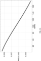
- Fig. 9 illustrates a magnetic field gradient of 30 mT/m in the x direction.
- Fig. 10 illustrates a magnetic field gradient in the y direction.
- Fig. 11 illustrates a magnetic field gradient in the z direction.
- the current densities used to generate these gradient fields are: 0.54 A/mm 2 for the x coils, 0.62 A/mm 2 for the y coils, and 1.1 A/mm 2 for the z coils.
- Fig. 11 shows that the maximum gradient in the z direction occurs at 10 cm, which also lies at the center of the operational range. This design allows the highest gradient regions to occur at the center of the operational range, corresponding to the location of the hole on the IM nail inside the bone. The monotonic nature of the magnetic fields ensures a unique mapping of all points in space to the corresponding magnetic field values.
- the gradient fields have a range large enough to accommodate both of the ATOMS devices: the device on the IM nail and the device on the drill.
- the overlap is especially useful in the initial phase of the surgical procedure, when the ATOMS on the drill is far from the intended final location.
- the designed coil setup allows a working range of 15 cm - 20 cm, which is more than sufficient for a typical IM nailing surgery. As the drill comes closer to the desired final location, the resolution improves.
- the coils generating the magnetic field can be placed, for example, under the patient's leg in an operating theater bed, if the broken bone is within the leg.
- Fig. 12 The sequence of time-multiplexed measurements of the magnetic field gradients in each direction is shown in Fig. 12 . Only the x coils are switched on during the x phase, and similarly for the y and z phases. First, a wake up command is sent to bring the system out of sleep mode. Then, the x gradient coils are turned on and allowed to reach a steady state value in about 2 ms (ramp-up time due to current switching in coils). Following this step, the field measurement takes place in the next 1 ms, and then the x gradient coils are turned off. The switching off phase takes another 2 ms, thus making the whole step 5 ms long. The same set of events is repeated for the y and z gradient measurements.
- the 1 ms time window required to measure the field gradient in any given direction is dictated by the sensor used for magnetic field measurements.
- the reported time needed to make an accurate field measurement by the sensor described above is about 1 ms, thus requiring the gradients to be stable for at least that much time.
- This also implies that the sensor has to be turned on only for the desired 1 ms time window for the x phase, and then subsequently for the y and the z phases. Therefore, the total on time for the sensor is 3 ms in a 100 ms time frame. After all three measurements corresponding to x, y and z are made, the sensor and the coils are turned off for the next 85 ms through a sleep command.
- the person of ordinary skill in the art will understand that the above parameter values are exemplary, and if using a different sensor having different characteristics, a different measurement time would be employed.
- ATOMS performs data processing and field value transmission through an RF signal. This step provides a visual feedback to the surgeon monitoring the updated computer screen (image refresh phase) and gives the surgeon enough time for maneuvering the drill to the updated location.
- a second ATOMS is located on the drill, the position of which is also constantly displayed on the computer screen.
- the complete process makes the duty cycle for the gradient switching to be 5% for each of the coils, including the switching time. In some embodiments, 10 such measurements can be carried out per second. This reduces the time to locate the hole in IM nailing surgery to only a couple of seconds, which is a major advantage over the existing solutions which take a couple of minutes along with continuous fluoroscopy to locate the hole in the IM nail.
- back scattering is used for wirelessly sending the measured field data to the external device for position tracking.
- This form of data transmission is particularly useful for low power applications.
- the two main components of a backscatter communication system are the backscatter transmitter and a reader.
- the reader comprises a radio frequency source along with a backscatter receiver.
- the RF signal is generated by the reader, while the backscatter transmitter modulates and reflects the signal to transmit its data to the backscatter receiver.
- the modulation produces a digital signal with a varying pulse width, based on the change in effective impedance of the RF coil in response to the impinging RF pulse.
- the RF source for ATOMS can operate at 13.56 MHz, which lies in the ISM band for biomedical implants.
- the tissue absorption at this frequency is much lower compared to the higher frequencies normally used for such applications.
- the Q factor of the RF coil, which determines the efficiency of the device, is also high at this frequency.
- wireless power transfer and databackscattering can be completely eliminated, in some embodiments, by having wired connectivity to the device. Since the drill bit is anyway tethered to a cable, it can be relatively easier to have wired connections for power transfer and data communication to the ATOMS device instead of performing the same over wireless medium. Another possibility is to perform optical tracking of the drill instead of having an ATOMS device for its positioning.
- the use of infrared based light emitting diodes is known to the person of ordinary skill in the art, for optical tracking of surgical tools. Gyroscope assisted tracking and passive markers like retro-reflective spheres, disks are also potential candidates for the same.
- ATOMS can be implanted inside human body, it is essential to hermetically seal the device using a bio-compatible plastic.
- encapsulation is carried out with polyetheretherketone (PEEK).
- PEEK has widespread use in prostheses, dental products and replacements for metal implants inside human body.
- an on-chip clock synchronizes the time for the sensor and the gradient coils.
- This synchronization can be achieved by implementing an ultra low power relaxation oscillator which consumes a total power of less than 1 nW, an extremely negligible amount compared to the 10 ⁇ W of power consumed by the 3D magnetic sensor.
- the magnetic field data obtained from the sensor is used to modulate the RF signal coming from the backscatter reader.
- the modulated signal is read by the backscatter receiver located externally. The modulation process is not power hungry and therefore the major power consumption of ATOMS comes from the 3D magnetic sensor.
- the average power consumed by the magnetic sensor is 0.3 ⁇ W as it remains on only for 3 ms out of 100 ms.
- the other circuit blocks, as described above in the present disclosure consume negligible power compared to the sensor. Therefore, the average power consumption of ATOMS can be approximately less than 1 ⁇ W.
- battery based solutions can be used, as they can easily provide the required power for the duration of an IM nailing operation.
- a rechargeable solid state bare die can be used.
- the battery footprint for example, can be 1.7 mm x 2.25 mm x 0.2 mm, which is well within the dimensions of ATOMS and can be easily incorporated into the complete system.
- the average heat loss from the coils is expected to be 8 W.
- this causes an increase in the coil temperature of less than 0.1° C, assuming copper metal is used for the coils.
- This negligible amount of heat relaxes the constraints on cooling mechanism, which reduces the overall complexity and cost of the system.
- the heating issue can be resolved by placing a cooling fan below the coil setup, and encapsulating the complete setup with a thermal insulator.
- Fig. 13 illustrates an exemplary PCB with a Hall sensor (1305), and an application specific integrated circuit (ASIC) chip (1310), comprising a power management block, and communication modules with the Hall sensor and wake up signals.
- the 3D magnetic Hall sensor, ASIC chip and the RF coils are all mounted on a printed circuit board (PCB) which is 10mm by 5mm (a typical implant size for ATOMS device).
- the sensor is soldered on the PCB and then connected to the ASIC through copper traces.
- the ASIC itself is wire-bonded to the PCB using very fine strands of gold wire.
- the RF coils are mounted all around the PCB and then connected to the ASIC through copper traces.
- the back of the PCB contains storage capacitors which store power received from the coils.
- the storage capacitors store the power received from the RF coils which can then be used during the measurement phase. Enough time is provided between consecutive measurements for the storage capacitors to re-charge to their required values. Table 1 lists some exemplary specifications for individual components of a sensor.
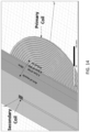
- the RF coils can be modelled as a composition of muscle, fat and skin having a depth of 4 cm, 2.5 cm and 0.5 cm respectively.
- the primary coil in this simulation is kept 3 cm above the skin, giving a total separation of 10 cm between the coils.
- the complete simulation setup is shown in Fig. 14 and the extracted parameters are listed in Table 2.
- the coupling coefficient between the coils in presence of human tissue is 0.001624. This value can provide a few milliWatts of power at the implant depth.
- the power consumption of the sensor can be restricted to be 1 mW for the complete ATOMS device, including the magnetic field sensor.
- the ASIC chip discussed above is responsible for (a) power reception and distribution; (b) data collection, processing and emission; and (c) wake-up when triggered by externally transmitted RF signal.
- the ASIC chip has three major components as described in the following, and as illustrated in Fig. 15 : a power management unit, an RF wake up module, and a data acquisition unit.
- the power management unit handles the power requirements.
- the RF power for example sent wirelessly at 13.56 MHz, is converted into DC power using a rectifier, which forms the front-end of the PMU block. Since the power received depends on the distance and alignment between the primary and secondary coils, it is expected to vary during the IM nailing operation. This power variation can lead to much higher voltage being induced at the secondary coil when the separation decreases, which in turn can damage the whole circuitry. In order to keep this induced in safe range, voltage limiters are used in the PMU.
- the rectified voltage (typically 0.6 V) may need to be boosted up because the subsequent circuit blocks and the sensor usually need higher voltages to operate correctly.
- the voltage boost can be achieved by a charge pump circuit, which can, for example, boost the rectified voltage by a factor of 4.
- the charge pump output voltage is then fed to regulators to produce three stable and regulated voltages (1520): (a) VDD_S is 2.4 V and is used as supply voltage for the sensor; (b) VDD_A is 1 V and is used as supply voltage for the analog circuit blocks of the ASIC; (c) VDD_D is 0.5 V and is used as supply voltage for the digital circuit blocks of the ASIC. To generate these supply voltages, other circuit blocks like bias voltage generators and current generators can be used.
- Table 2 lists coil parameters. Table 2 Parameter Primary Coil Secondary Coil Inductance 43.457 ⁇ H 11.797 ⁇ H Quality Factor 272K 97.9 Resistance 13.6m ⁇ 10.266 ⁇ Cross Section 5mm x 5mm 0.1mm x 0.1mm Area 24cm diameter 4.6mm x 12mm Coupling Coefficient 0.001624
- the RF coils can serve two functions: WPT and data communication.
- the backscatter modulation switch which connects the rectified voltage to charge pump, controls which of the two functions take place. In the normally ON mode, the switch allows the power to be transferred to the charge pump, and hence facilitates WPT. In the OFF mode, it disconnects the charge pump and modulates the RF signal on the coil, to backscatter the data to the external receiver.
- the wake-up signal in some embodiments it is possible to transmit to the ASIC chip a 13.56 MHz RF signal, amplitude modulated with a 17 kHz pulse.
- an envelope detector To decode the wake-up signal from the RF carrier, an envelope detector first removes the 13.56 MHz frequency component from the signal, obtaining a 17 kHz pulse at its output. This pulse is further processed and demodulated in subsequent stages. Since reset signals are also transmitted to the ASIC in a similar fashion to the wake up pulse, a digital block is used to distinguish the wake up pulse from the reset signal. The output of the digital block is then used as a wake-up signal to initiate the magnetic field measurement by the sensor, or as a reset signal which resets the sensor interface block and the sensor.
- the sensor is controlled by the data acquisition unit, which sends the commands needed for its operation.
- the sensor connects directly to the I2C interface on the ASIC, which follows the standard I2C protocol for data transfer, known to the person of ordinary skill in the art.
- This digital module provides the data and clock signals to the sensor and controls both of them as per the protocol.
- the 100 kHz I2C clock is generated on the ASIC using a ring-oscillator.
- the data line is bi-directional and is used for sending and receiving signals from the sensor.
- the sensor interface module in this unit controls the I2C interface module by activating it only when the wake-up signal is received. It also collects the data from the I2C interface module after a measurement is completed. This data is then used to control the backscatter switch, which modulates the RF signal across the coils in transmission phase.
- a complete ASIC chip can be designed, with a 65 nanometer CMOS mixed signal, low power RF process.
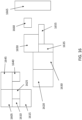
- Fig. 16 illustrates limiters (1605,1615); a rectifier (1610); a charge pump (1625); a current source (1645); an oscillator (1640); band gap reference (1620); voltage regulators (1630); RF wake up (1635); a regulator (1650); a digital processing block (1655); a I2C interface (1660); and a reference voltage generator (1665).
- the space surrounding the above components can also house noise cancellation and decoupling capacitors.
- Fig. 17 shows the simulation results for the PMU unit.
- the topmost waveforms (1705) are for the RF to DC power conversion by the rectifier which produces a stable DC voltage of 0.6 V from the alternating 13.56 MHz RF signal.
- the middle waveforms (1710) are for reference voltages, while curves (1715) are for the three supply voltages VDD_S, VDD_A and VDD_D.
- Fig. 18 shows the RF-wake-up block waveforms.
- the topmost waveform (1805) is for the amplitude modulated RF carrier (13.56 MHz) with a 17 kHz message signal on top of it. This has to be demodulated and processed to retrieve the 17 kHz message signal from the carrier, as shown in the middle waveform (1810).
- the last waveform (1815) is the output of the digital block and is generated after mapping the duration of the message signal to a fixed value. This is used as a wake-up signal for subsequent blocks.
- Fig. 19 shows the waveforms of the data acquisition unit.
- the I2C interface block in this unit connects to the sensor through clock and data signals, shown as (1905) and (1910) respectively.
- the data collected is then transferred to the sensor interface block for processing.
- the processed data is illustrated as (1915). This is sent to the backscatter switch to modulate the RF signal's amplitude at a frequency of 50 kHz.
- the enable signal is illustrated as (1920) and controls the data flow direction between the sensor and the ASIC chip.
- Fig. 20 shows the backscatter modulation waveforms.
- the modulated signal appears across the RF coils, as shown in (2005) and is received by an external receiver.
- the modulating signal is shown in (2010).
- the rectifier consumes major part of the current as shown in (2015).
- the backscatter switch sinks almost all of the current as shown in (2020), and produces the required modulation on the RF signal.
- the magnetic field gradient coils needs to produce a field gradient of 30 mT/m (in each direction) in order to achieve a spatial resolution of 100 ⁇ m for the given sensor resolution of 3.1 ⁇ T. It is possible to reduce the volume of the gradient coils drastically and obtain the above field values by using coils that measure 30 cm x 30 cm x 1 cm, as shown in Figs. 21-22 .
- Fig. 21 illustrates a top view of the coils, in perspective, while Fig. 22 illustrates the bottom view. This result was possible by increasing the current density for each coil setup, and by using higher current values.
- the x coils in this example, need a current of 18 A, the y coils need 20 A, and the z coils need 13 A to generate a gradient of 30 mT/m in all three dimensions.
- the simulated gradient plots are shown in Figs. 23-25 .
- the high currents could generate serious heating issues for the coils.
- time-multiplexing of the field measurement is carried out, which turns the gradient coils ON and produces a stable gradient for only 1 ms, the time needed by sensor to make a measurement. For the remainder of the time slot, which is approximately 80 ms in every time frame of 100 ms, the corresponding gradient coils are OFF and the heating effect is negligible.
- the 20 ms time window for which the coils are ON also takes into account the finite rise and fall time of the current, due to self-inductance of the coils.
- the coils can be fabricated with litz wire.
- Litz wire is a specialized multistrand wire that reduces skin effects and proximity losses.
- the wire can be wound on a 3D printed plastic base.
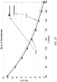
- a very good match can be observed between the simulated (2605,2705) and measured (2610,2710) gradient profiles for exemplary coils fabricated as prototypes, as shown in Figs. 26 and 27 for the z and x coils respectively.
- the gradient profile for the y coils was similar to that of the x coils.
- the magnetic sensors in the devices can detect three field components in three orthogonal axes.
- the system can display relative alignment and locations of the first and second sensors attached, for example, to a surgical nail for bone repair, and a surgical drill.
- the surgical device e.g. the drill
- the surgical device does not transmit its data wirelessly, but it is instead wired to the computer or the display.
Landscapes
- Health & Medical Sciences (AREA)
- Surgery (AREA)
- Life Sciences & Earth Sciences (AREA)
- Engineering & Computer Science (AREA)
- Medical Informatics (AREA)
- General Health & Medical Sciences (AREA)
- Veterinary Medicine (AREA)
- Public Health (AREA)
- Biomedical Technology (AREA)
- Heart & Thoracic Surgery (AREA)
- Nuclear Medicine, Radiotherapy & Molecular Imaging (AREA)
- Molecular Biology (AREA)
- Animal Behavior & Ethology (AREA)
- Orthopedic Medicine & Surgery (AREA)
- Oral & Maxillofacial Surgery (AREA)
- Dentistry (AREA)
- Physics & Mathematics (AREA)
- Electromagnetism (AREA)
- Pathology (AREA)
- Robotics (AREA)
- Neurology (AREA)
- Magnetic Resonance Imaging Apparatus (AREA)
Claims (7)
- Ein System, das Folgendes beinhaltet:
einen ersten Sensor, der konfiguriert ist, um während eines chirurgischen Eingriffs in einen Patienten eingeführt zu werden, wobei der erste Sensor Folgendes beinhaltet:einen ersten Magnetsensor, der konfiguriert ist, um einen ersten Magnetfeldwert zu detektieren,einen ersten integrierten Schaltungschip, der konfiguriert ist, um Daten von dem ersten Magnetsensor zu verarbeiten, undeine erste Hochfrequenzspule (515), die konfiguriert ist, um Daten zu übertragen, die von dem ersten integrierten Schaltungschip basierend auf dem ersten Magnetfeld verarbeitet werden;einen zweiten Sensor, der an einem chirurgischen Instrument befestigt ist, wobei der zweite Sensor Folgendes beinhaltet:einen zweiten Magnetsensor, der konfiguriert ist, um einen zweiten Magnetfeldwert zu detektieren, undeinen zweiten integrierten Schaltungschip, der konfiguriert ist, um Daten von dem zweiten Magnetsensor zu verarbeiten; undeine Vielzahl von Spulen, die konfiguriert sind, um einen Magnetfeldgradienten (405) innerhalb eines Volumens zu erzeugen, in dem der chirurgische Eingriff stattfindet,wobei der Magnetfeldgradient (405) einen eindeutigen Feldwert an jeder räumlichen Stelle aufweist;dadurch gekennzeichnet, dass der erste integrierte Schaltungschip ferner konfiguriert ist, um Leistung, die dem ersten Magnetsensor und der ersten Hochfrequenzspule (515) zugewiesen ist, zeitlich zu multiplexen, und dass das Multiplexen des ersten integrierten Schaltungschips Folgendes beinhaltet:ein Aufwecksignal für den ersten Magnetsensor, das von der ersten Hochfrequenzspule (515) empfangen wird;eine erste Zeitzuweisung, um eine x-Komponente des Magnetfeldgradienten zu detektieren;eine zweite Zeitzuweisung, um eine y-Komponente des Magnetfeldgradienten zu detektieren;eine dritte Zeitzuweisung, um eine z-Komponente des Magnetfeldgradienten zu detektieren;eine Datenübertragung durch die erste Hochfrequenzspule (515); undein Schlafsignal für den ersten Magnetsensor. - System gemäß Anspruch 1, wobei der erste Sensor ferner eine Batterie beinhaltet und/oder wobei die erste Hochfrequenzspule (515) des ersten Sensors ferner konfiguriert ist, um drahtlos Leistung zu empfangen.
- System gemäß einem der Ansprüche 1-2, wobei der erste Magnetsensor und der zweite Magnetsensor Hall-Sensoren sind, die konfiguriert sind, um drei Feldkomponenten in drei orthogonalen Achsen zu erfassen, und der Magnetfeldgradient monoton ist.
- System gemäß einem der Ansprüche 1-3, wobei die Vielzahl von Spulen mindestens Folgendes beinhaltet:eine erste elliptische x-Spule (605) und eine zweite elliptische x-Spule (705), die konfiguriert sind, um Ströme aufzunehmen, die in entgegengesetzte Richtungen zueinander fließen;eine erste elliptische y-Spule (610) und eine zweite elliptische y-Spule (710), die konfiguriert sind, um Ströme aufzunehmen, die in entgegengesetzte Richtungen zueinander fließen, wobei die erste und die zweite elliptische y-Spule (610, 710) in einer Ebene parallel zu der ersten und der zweiten elliptischen x-Spule (605, 705) liegen und um 90° relativ zu der ersten und der zweiten elliptischen x-Spule (605, 705) gedreht sind; undeine z-Spule (615).
- System gemäß einem der Ansprüche 1-4, wobei der erste Sensor konfiguriert ist, um in einem chirurgischen Nagel (110, 2805) befestigt zu werden, der zweite Sensor konfiguriert ist, um an einem chirurgischen Bohrer befestigt zu werden, und der chirurgische Eingriff das Ausrichten des chirurgischen Bohrers und des chirurgischen Nagels (110, 2805) beinhaltet.
- System gemäß einem der Ansprüche 1-5, wobei der erste und der zweite Magnetsensor eine Magnetfeldauflösung von mindestens 3,1 mT, eine durchschnittliche Leistungsaufnahme von weniger als 10 mW und einen dynamischen Feldmessbereich von ± 35 mT für jede Magnetfeldachsenkomponente aufweisen und/oder der Magnetfeldgradient 30 mT/m beträgt.
- System gemäß einem der Ansprüche 1-6, das ferner eine zweite Hochfrequenzspule beinhaltet, die konfiguriert ist, um Daten zu übertragen, die von dem zweiten integrierten Schaltungschip basierend auf dem zweiten Magnetfeld verarbeitet werden.
Applications Claiming Priority (2)
| Application Number | Priority Date | Filing Date | Title |
|---|---|---|---|
| US201862688235P | 2018-06-21 | 2018-06-21 | |
| PCT/US2019/031877 WO2019245668A1 (en) | 2018-06-21 | 2019-05-10 | Surgical alignment by magnetic field gradient localization |
Publications (3)
| Publication Number | Publication Date |
|---|---|
| EP3809987A1 EP3809987A1 (de) | 2021-04-28 |
| EP3809987A4 EP3809987A4 (de) | 2022-05-18 |
| EP3809987B1 true EP3809987B1 (de) | 2024-02-21 |
Family
ID=68981153
Family Applications (1)
| Application Number | Title | Priority Date | Filing Date |
|---|---|---|---|
| EP19822267.1A Active EP3809987B1 (de) | 2018-06-21 | 2019-05-10 | Chirurgische ausrichtung durch magnetfeldgradientenlokalisierung |
Country Status (5)
| Country | Link |
|---|---|
| US (2) | US11399848B2 (de) |
| EP (1) | EP3809987B1 (de) |
| KR (1) | KR102677887B1 (de) |
| CN (1) | CN112312845B (de) |
| WO (1) | WO2019245668A1 (de) |
Families Citing this family (5)
| Publication number | Priority date | Publication date | Assignee | Title |
|---|---|---|---|---|
| WO2019245668A1 (en) | 2018-06-21 | 2019-12-26 | California Institute Of Technology | Surgical alignment by magnetic field gradient localization |
| EP4058819A4 (de) | 2019-11-13 | 2024-01-10 | California Institute of Technology | Elektromagnetische gradientenspulenvorrichtung zur lokalisierung von mikrovorrichtungen |
| US20220071730A1 (en) * | 2020-09-09 | 2022-03-10 | Tychon Technologies, Inc. | Position-sensitive magnetically-sensitive tags for surgical procedures |
| US11925349B2 (en) * | 2021-02-26 | 2024-03-12 | Cilag Gmbh International | Adjustment to transfer parameters to improve available power |
| WO2025160140A1 (en) * | 2024-01-23 | 2025-07-31 | Cianna Medical, Inc. | Marker reflector systems with light emitters |
Family Cites Families (31)
| Publication number | Priority date | Publication date | Assignee | Title |
|---|---|---|---|---|
| US5558091A (en) * | 1993-10-06 | 1996-09-24 | Biosense, Inc. | Magnetic determination of position and orientation |
| US5879297A (en) * | 1997-05-08 | 1999-03-09 | Lucent Medical Systems, Inc. | System and method to determine the location and orientation of an indwelling medical device |
| US6529127B2 (en) * | 1997-07-11 | 2003-03-04 | Microstrain, Inc. | System for remote powering and communication with a network of addressable, multichannel sensing modules |
| US5882304A (en) * | 1997-10-27 | 1999-03-16 | Picker Nordstar Corporation | Method and apparatus for determining probe location |
| US6261247B1 (en) * | 1998-12-31 | 2001-07-17 | Ball Semiconductor, Inc. | Position sensing system |
| US7020531B1 (en) * | 2001-05-01 | 2006-03-28 | Intrapace, Inc. | Gastric device and suction assisted method for implanting a device on a stomach wall |
| US7033313B2 (en) * | 2002-12-11 | 2006-04-25 | No. 182 Corporate Ventures Ltd. | Surgically implantable hearing aid |
| US7029478B2 (en) * | 2003-09-30 | 2006-04-18 | Depuy Products, Inc. | Method and apparatus for distal targeting of locking screws in intramedullary nails |
| EP1833366A1 (de) | 2004-12-17 | 2007-09-19 | Olympus Corporation | Positionsnachweissystem, führungssystem, positionsnachweismethode, medizinprodukt und medizinisches magnetinduktions- und positionsnachweissystem |
| CN1718152A (zh) * | 2005-06-29 | 2006-01-11 | 中国科学院合肥物质科学研究院 | 体内探测器外磁场驱动装置及方法 |
| US9220514B2 (en) * | 2008-02-28 | 2015-12-29 | Smith & Nephew, Inc. | System and method for identifying a landmark |
| US8945147B2 (en) | 2009-04-27 | 2015-02-03 | Smith & Nephew, Inc. | System and method for identifying a landmark |
| KR101713351B1 (ko) | 2009-04-27 | 2017-03-07 | 스미스 앤드 네퓨, 인크. | 랜드마크를 식별하는 시스템 및 방법 |
| CN102892364B (zh) * | 2009-10-06 | 2016-03-16 | 史密夫和内修有限公司 | 瞄准整形外科器械的标志物 |
| JP4932971B2 (ja) | 2010-03-26 | 2012-05-16 | オリンパスメディカルシステムズ株式会社 | カプセル型医療装置用誘導システム |
| US20130218007A1 (en) * | 2010-11-01 | 2013-08-22 | Smith & Nephew, Inc. | Targeting landmarks of orthopaedic devices |
| CN103607946A (zh) * | 2011-01-20 | 2014-02-26 | 埃纳威医疗有限公司 | 估计物体的位置和取向的系统和方法 |
| CN102073024B (zh) * | 2011-01-31 | 2013-03-06 | 汕头市超声仪器研究所有限公司 | 一种手持式超低场mri的成像装置 |
| AU2012253862B2 (en) * | 2011-05-06 | 2016-09-29 | Smith & Nephew, Inc. | Targeting landmarks of orthopaedic devices |
| WO2013001399A2 (en) * | 2011-06-27 | 2013-01-03 | Koninklijke Philips Electronics N.V. | Magnetic resonance imaging of bone tissue |
| LT2939601T (lt) * | 2011-09-06 | 2019-02-25 | Ezono Ag | Magnetinis medicininis įrenginys |
| CN105229458A (zh) * | 2013-03-14 | 2016-01-06 | 加州理工学院 | 检测电子和电化学能源单元异常 |
| EP2851702A1 (de) * | 2013-09-11 | 2015-03-25 | Seiko Epson Corporation | Magnetische Abschirmvorrichtung und magnetisches Abschirmverfahren |
| CN103529405A (zh) * | 2013-10-28 | 2014-01-22 | 中国医学科学院生物医学工程研究所 | 一种具有高频脉冲磁场三维动态监测功能的磁刺激线圈 |
| US9915641B2 (en) | 2013-12-04 | 2018-03-13 | California Institute Of Technology | Sensing and actuation of biological function using addressable transmitters operated as magnetic spins |
| US10258256B2 (en) * | 2014-12-09 | 2019-04-16 | TechMah Medical | Bone reconstruction and orthopedic implants |
| WO2017127722A1 (en) * | 2016-01-20 | 2017-07-27 | Lucent Medical Systems, Inc. | Low-frequency electromagnetic tracking |
| US10635172B1 (en) * | 2016-10-04 | 2020-04-28 | Facebook Technologies, Llc | Bend angle sensing mechanism for wearable device |
| JP6256962B1 (ja) * | 2017-06-21 | 2018-01-10 | 朝日インテック株式会社 | 磁気式の方位・位置測定装置 |
| US10517612B2 (en) * | 2017-09-19 | 2019-12-31 | Biosense Webster (Israel) Ltd. | Nail hole guiding system |
| WO2019245668A1 (en) | 2018-06-21 | 2019-12-26 | California Institute Of Technology | Surgical alignment by magnetic field gradient localization |
-
2019
- 2019-05-10 WO PCT/US2019/031877 patent/WO2019245668A1/en not_active Ceased
- 2019-05-10 EP EP19822267.1A patent/EP3809987B1/de active Active
- 2019-05-10 US US16/409,727 patent/US11399848B2/en active Active
- 2019-05-10 KR KR1020207036163A patent/KR102677887B1/ko active Active
- 2019-05-10 CN CN201980041605.6A patent/CN112312845B/zh active Active
-
2022
- 2022-07-18 US US17/813,177 patent/US11903595B2/en active Active
Also Published As
| Publication number | Publication date |
|---|---|
| WO2019245668A1 (en) | 2019-12-26 |
| EP3809987A1 (de) | 2021-04-28 |
| US20220346811A1 (en) | 2022-11-03 |
| CN112312845A (zh) | 2021-02-02 |
| EP3809987A4 (de) | 2022-05-18 |
| US11903595B2 (en) | 2024-02-20 |
| KR20210011957A (ko) | 2021-02-02 |
| CN112312845B (zh) | 2024-05-24 |
| US20190388105A1 (en) | 2019-12-26 |
| KR102677887B1 (ko) | 2024-06-21 |
| US11399848B2 (en) | 2022-08-02 |
Similar Documents
| Publication | Publication Date | Title |
|---|---|---|
| US11903595B2 (en) | Surgical alignment by magnetic field gradient localization | |
| CA2487162C (en) | Digital wireless position sensor | |
| EP1727486B1 (de) | Implantierbarer Marker | |
| US10390891B2 (en) | Hologram lens for positioning an orthopedic implant | |
| EP1854406B1 (de) | Verfolgung der Position von passiven Transpondern auf Resonanzbasis | |
| AU2003213476B2 (en) | Distal targeting of locking screws in intramedullary nails | |
| AU2005200900B2 (en) | Position sensing system for orthopedic applications | |
| US9526441B2 (en) | Targeting landmarks of orthopaedic devices | |
| US20080287781A1 (en) | Registration Methods and Apparatus | |
| US10517612B2 (en) | Nail hole guiding system | |
| US20060241397A1 (en) | Reference pad for position sensing | |
| US20230067388A1 (en) | System for a dynamic electrically stimulating rod-like orthopedic implant | |
| EP3415104A1 (de) | Positionierungswerkzeug für ein orthopädisches implantat | |
| HK1075813A (en) | Digital wireless position sensor |
Legal Events
| Date | Code | Title | Description |
|---|---|---|---|
| STAA | Information on the status of an ep patent application or granted ep patent |
Free format text: STATUS: THE INTERNATIONAL PUBLICATION HAS BEEN MADE |
|
| PUAI | Public reference made under article 153(3) epc to a published international application that has entered the european phase |
Free format text: ORIGINAL CODE: 0009012 |
|
| STAA | Information on the status of an ep patent application or granted ep patent |
Free format text: STATUS: REQUEST FOR EXAMINATION WAS MADE |
|
| 17P | Request for examination filed |
Effective date: 20201222 |
|
| AK | Designated contracting states |
Kind code of ref document: A1 Designated state(s): AL AT BE BG CH CY CZ DE DK EE ES FI FR GB GR HR HU IE IS IT LI LT LU LV MC MK MT NL NO PL PT RO RS SE SI SK SM TR |
|
| AX | Request for extension of the european patent |
Extension state: BA ME |
|
| DAV | Request for validation of the european patent (deleted) | ||
| DAX | Request for extension of the european patent (deleted) | ||
| A4 | Supplementary search report drawn up and despatched |
Effective date: 20220414 |
|
| RIC1 | Information provided on ipc code assigned before grant |
Ipc: G01B 7/31 20060101ALN20220408BHEP Ipc: A61B 17/17 20060101AFI20220408BHEP |
|
| GRAP | Despatch of communication of intention to grant a patent |
Free format text: ORIGINAL CODE: EPIDOSNIGR1 |
|
| STAA | Information on the status of an ep patent application or granted ep patent |
Free format text: STATUS: GRANT OF PATENT IS INTENDED |
|
| RIC1 | Information provided on ipc code assigned before grant |
Ipc: G01B 7/31 20060101ALN20230918BHEP Ipc: A61B 17/17 20060101AFI20230918BHEP |
|
| INTG | Intention to grant announced |
Effective date: 20231002 |
|
| GRAS | Grant fee paid |
Free format text: ORIGINAL CODE: EPIDOSNIGR3 |
|
| GRAA | (expected) grant |
Free format text: ORIGINAL CODE: 0009210 |
|
| STAA | Information on the status of an ep patent application or granted ep patent |
Free format text: STATUS: THE PATENT HAS BEEN GRANTED |
|
| AK | Designated contracting states |
Kind code of ref document: B1 Designated state(s): AL AT BE BG CH CY CZ DE DK EE ES FI FR GB GR HR HU IE IS IT LI LT LU LV MC MK MT NL NO PL PT RO RS SE SI SK SM TR |
|
| REG | Reference to a national code |
Ref country code: GB Ref legal event code: FG4D |
|
| REG | Reference to a national code |
Ref country code: CH Ref legal event code: EP |
|
| REG | Reference to a national code |
Ref country code: DE Ref legal event code: R096 Ref document number: 602019047013 Country of ref document: DE |
|
| REG | Reference to a national code |
Ref country code: IE Ref legal event code: FG4D |
|
| REG | Reference to a national code |
Ref country code: LT Ref legal event code: MG9D |
|
| REG | Reference to a national code |
Ref country code: NL Ref legal event code: MP Effective date: 20240221 |
|
| PG25 | Lapsed in a contracting state [announced via postgrant information from national office to epo] |
Ref country code: IS Free format text: LAPSE BECAUSE OF FAILURE TO SUBMIT A TRANSLATION OF THE DESCRIPTION OR TO PAY THE FEE WITHIN THE PRESCRIBED TIME-LIMIT Effective date: 20240621 |
|
| PG25 | Lapsed in a contracting state [announced via postgrant information from national office to epo] |
Ref country code: LT Free format text: LAPSE BECAUSE OF FAILURE TO SUBMIT A TRANSLATION OF THE DESCRIPTION OR TO PAY THE FEE WITHIN THE PRESCRIBED TIME-LIMIT Effective date: 20240221 |
|
| PG25 | Lapsed in a contracting state [announced via postgrant information from national office to epo] |
Ref country code: GR Free format text: LAPSE BECAUSE OF FAILURE TO SUBMIT A TRANSLATION OF THE DESCRIPTION OR TO PAY THE FEE WITHIN THE PRESCRIBED TIME-LIMIT Effective date: 20240522 |
|
| REG | Reference to a national code |
Ref country code: AT Ref legal event code: MK05 Ref document number: 1658392 Country of ref document: AT Kind code of ref document: T Effective date: 20240221 |
|
| PG25 | Lapsed in a contracting state [announced via postgrant information from national office to epo] |
Ref country code: HR Free format text: LAPSE BECAUSE OF FAILURE TO SUBMIT A TRANSLATION OF THE DESCRIPTION OR TO PAY THE FEE WITHIN THE PRESCRIBED TIME-LIMIT Effective date: 20240221 Ref country code: RS Free format text: LAPSE BECAUSE OF FAILURE TO SUBMIT A TRANSLATION OF THE DESCRIPTION OR TO PAY THE FEE WITHIN THE PRESCRIBED TIME-LIMIT Effective date: 20240521 Ref country code: NL Free format text: LAPSE BECAUSE OF FAILURE TO SUBMIT A TRANSLATION OF THE DESCRIPTION OR TO PAY THE FEE WITHIN THE PRESCRIBED TIME-LIMIT Effective date: 20240221 |
|
| PG25 | Lapsed in a contracting state [announced via postgrant information from national office to epo] |
Ref country code: ES Free format text: LAPSE BECAUSE OF FAILURE TO SUBMIT A TRANSLATION OF THE DESCRIPTION OR TO PAY THE FEE WITHIN THE PRESCRIBED TIME-LIMIT Effective date: 20240221 |
|
| PG25 | Lapsed in a contracting state [announced via postgrant information from national office to epo] |
Ref country code: AT Free format text: LAPSE BECAUSE OF FAILURE TO SUBMIT A TRANSLATION OF THE DESCRIPTION OR TO PAY THE FEE WITHIN THE PRESCRIBED TIME-LIMIT Effective date: 20240221 |
|
| PG25 | Lapsed in a contracting state [announced via postgrant information from national office to epo] |
Ref country code: RS Free format text: LAPSE BECAUSE OF FAILURE TO SUBMIT A TRANSLATION OF THE DESCRIPTION OR TO PAY THE FEE WITHIN THE PRESCRIBED TIME-LIMIT Effective date: 20240521 Ref country code: NO Free format text: LAPSE BECAUSE OF FAILURE TO SUBMIT A TRANSLATION OF THE DESCRIPTION OR TO PAY THE FEE WITHIN THE PRESCRIBED TIME-LIMIT Effective date: 20240521 Ref country code: NL Free format text: LAPSE BECAUSE OF FAILURE TO SUBMIT A TRANSLATION OF THE DESCRIPTION OR TO PAY THE FEE WITHIN THE PRESCRIBED TIME-LIMIT Effective date: 20240221 Ref country code: LT Free format text: LAPSE BECAUSE OF FAILURE TO SUBMIT A TRANSLATION OF THE DESCRIPTION OR TO PAY THE FEE WITHIN THE PRESCRIBED TIME-LIMIT Effective date: 20240221 Ref country code: IS Free format text: LAPSE BECAUSE OF FAILURE TO SUBMIT A TRANSLATION OF THE DESCRIPTION OR TO PAY THE FEE WITHIN THE PRESCRIBED TIME-LIMIT Effective date: 20240621 Ref country code: HR Free format text: LAPSE BECAUSE OF FAILURE TO SUBMIT A TRANSLATION OF THE DESCRIPTION OR TO PAY THE FEE WITHIN THE PRESCRIBED TIME-LIMIT Effective date: 20240221 Ref country code: GR Free format text: LAPSE BECAUSE OF FAILURE TO SUBMIT A TRANSLATION OF THE DESCRIPTION OR TO PAY THE FEE WITHIN THE PRESCRIBED TIME-LIMIT Effective date: 20240522 Ref country code: FI Free format text: LAPSE BECAUSE OF FAILURE TO SUBMIT A TRANSLATION OF THE DESCRIPTION OR TO PAY THE FEE WITHIN THE PRESCRIBED TIME-LIMIT Effective date: 20240221 Ref country code: ES Free format text: LAPSE BECAUSE OF FAILURE TO SUBMIT A TRANSLATION OF THE DESCRIPTION OR TO PAY THE FEE WITHIN THE PRESCRIBED TIME-LIMIT Effective date: 20240221 Ref country code: BG Free format text: LAPSE BECAUSE OF FAILURE TO SUBMIT A TRANSLATION OF THE DESCRIPTION OR TO PAY THE FEE WITHIN THE PRESCRIBED TIME-LIMIT Effective date: 20240221 Ref country code: AT Free format text: LAPSE BECAUSE OF FAILURE TO SUBMIT A TRANSLATION OF THE DESCRIPTION OR TO PAY THE FEE WITHIN THE PRESCRIBED TIME-LIMIT Effective date: 20240221 |
|
| PG25 | Lapsed in a contracting state [announced via postgrant information from national office to epo] |
Ref country code: PT Free format text: LAPSE BECAUSE OF FAILURE TO SUBMIT A TRANSLATION OF THE DESCRIPTION OR TO PAY THE FEE WITHIN THE PRESCRIBED TIME-LIMIT Effective date: 20240621 Ref country code: PL Free format text: LAPSE BECAUSE OF FAILURE TO SUBMIT A TRANSLATION OF THE DESCRIPTION OR TO PAY THE FEE WITHIN THE PRESCRIBED TIME-LIMIT Effective date: 20240221 |
|
| PG25 | Lapsed in a contracting state [announced via postgrant information from national office to epo] |
Ref country code: SE Free format text: LAPSE BECAUSE OF FAILURE TO SUBMIT A TRANSLATION OF THE DESCRIPTION OR TO PAY THE FEE WITHIN THE PRESCRIBED TIME-LIMIT Effective date: 20240221 Ref country code: PT Free format text: LAPSE BECAUSE OF FAILURE TO SUBMIT A TRANSLATION OF THE DESCRIPTION OR TO PAY THE FEE WITHIN THE PRESCRIBED TIME-LIMIT Effective date: 20240621 Ref country code: PL Free format text: LAPSE BECAUSE OF FAILURE TO SUBMIT A TRANSLATION OF THE DESCRIPTION OR TO PAY THE FEE WITHIN THE PRESCRIBED TIME-LIMIT Effective date: 20240221 Ref country code: LV Free format text: LAPSE BECAUSE OF FAILURE TO SUBMIT A TRANSLATION OF THE DESCRIPTION OR TO PAY THE FEE WITHIN THE PRESCRIBED TIME-LIMIT Effective date: 20240221 |
|
| PG25 | Lapsed in a contracting state [announced via postgrant information from national office to epo] |
Ref country code: DK Free format text: LAPSE BECAUSE OF FAILURE TO SUBMIT A TRANSLATION OF THE DESCRIPTION OR TO PAY THE FEE WITHIN THE PRESCRIBED TIME-LIMIT Effective date: 20240221 |
|
| PG25 | Lapsed in a contracting state [announced via postgrant information from national office to epo] |
Ref country code: SM Free format text: LAPSE BECAUSE OF FAILURE TO SUBMIT A TRANSLATION OF THE DESCRIPTION OR TO PAY THE FEE WITHIN THE PRESCRIBED TIME-LIMIT Effective date: 20240221 |
|
| PG25 | Lapsed in a contracting state [announced via postgrant information from national office to epo] |
Ref country code: CZ Free format text: LAPSE BECAUSE OF FAILURE TO SUBMIT A TRANSLATION OF THE DESCRIPTION OR TO PAY THE FEE WITHIN THE PRESCRIBED TIME-LIMIT Effective date: 20240221 Ref country code: EE Free format text: LAPSE BECAUSE OF FAILURE TO SUBMIT A TRANSLATION OF THE DESCRIPTION OR TO PAY THE FEE WITHIN THE PRESCRIBED TIME-LIMIT Effective date: 20240221 |
|
| PG25 | Lapsed in a contracting state [announced via postgrant information from national office to epo] |
Ref country code: SK Free format text: LAPSE BECAUSE OF FAILURE TO SUBMIT A TRANSLATION OF THE DESCRIPTION OR TO PAY THE FEE WITHIN THE PRESCRIBED TIME-LIMIT Effective date: 20240221 |
|
| PG25 | Lapsed in a contracting state [announced via postgrant information from national office to epo] |
Ref country code: SM Free format text: LAPSE BECAUSE OF FAILURE TO SUBMIT A TRANSLATION OF THE DESCRIPTION OR TO PAY THE FEE WITHIN THE PRESCRIBED TIME-LIMIT Effective date: 20240221 Ref country code: SK Free format text: LAPSE BECAUSE OF FAILURE TO SUBMIT A TRANSLATION OF THE DESCRIPTION OR TO PAY THE FEE WITHIN THE PRESCRIBED TIME-LIMIT Effective date: 20240221 Ref country code: RO Free format text: LAPSE BECAUSE OF FAILURE TO SUBMIT A TRANSLATION OF THE DESCRIPTION OR TO PAY THE FEE WITHIN THE PRESCRIBED TIME-LIMIT Effective date: 20240221 Ref country code: EE Free format text: LAPSE BECAUSE OF FAILURE TO SUBMIT A TRANSLATION OF THE DESCRIPTION OR TO PAY THE FEE WITHIN THE PRESCRIBED TIME-LIMIT Effective date: 20240221 Ref country code: DK Free format text: LAPSE BECAUSE OF FAILURE TO SUBMIT A TRANSLATION OF THE DESCRIPTION OR TO PAY THE FEE WITHIN THE PRESCRIBED TIME-LIMIT Effective date: 20240221 Ref country code: CZ Free format text: LAPSE BECAUSE OF FAILURE TO SUBMIT A TRANSLATION OF THE DESCRIPTION OR TO PAY THE FEE WITHIN THE PRESCRIBED TIME-LIMIT Effective date: 20240221 |
|
| REG | Reference to a national code |
Ref country code: DE Ref legal event code: R097 Ref document number: 602019047013 Country of ref document: DE |
|
| PG25 | Lapsed in a contracting state [announced via postgrant information from national office to epo] |
Ref country code: IT Free format text: LAPSE BECAUSE OF FAILURE TO SUBMIT A TRANSLATION OF THE DESCRIPTION OR TO PAY THE FEE WITHIN THE PRESCRIBED TIME-LIMIT Effective date: 20240221 |
|
| PLBE | No opposition filed within time limit |
Free format text: ORIGINAL CODE: 0009261 |
|
| STAA | Information on the status of an ep patent application or granted ep patent |
Free format text: STATUS: NO OPPOSITION FILED WITHIN TIME LIMIT |
|
| REG | Reference to a national code |
Ref country code: CH Ref legal event code: PL |
|
| PG25 | Lapsed in a contracting state [announced via postgrant information from national office to epo] |
Ref country code: IT Free format text: LAPSE BECAUSE OF FAILURE TO SUBMIT A TRANSLATION OF THE DESCRIPTION OR TO PAY THE FEE WITHIN THE PRESCRIBED TIME-LIMIT Effective date: 20240221 |
|
| PG25 | Lapsed in a contracting state [announced via postgrant information from national office to epo] |
Ref country code: MC Free format text: LAPSE BECAUSE OF FAILURE TO SUBMIT A TRANSLATION OF THE DESCRIPTION OR TO PAY THE FEE WITHIN THE PRESCRIBED TIME-LIMIT Effective date: 20240221 |
|
| PG25 | Lapsed in a contracting state [announced via postgrant information from national office to epo] |
Ref country code: LU Free format text: LAPSE BECAUSE OF NON-PAYMENT OF DUE FEES Effective date: 20240510 |
|
| 26N | No opposition filed |
Effective date: 20241122 |
|
| PG25 | Lapsed in a contracting state [announced via postgrant information from national office to epo] |
Ref country code: MC Free format text: LAPSE BECAUSE OF FAILURE TO SUBMIT A TRANSLATION OF THE DESCRIPTION OR TO PAY THE FEE WITHIN THE PRESCRIBED TIME-LIMIT Effective date: 20240221 Ref country code: LU Free format text: LAPSE BECAUSE OF NON-PAYMENT OF DUE FEES Effective date: 20240510 Ref country code: CH Free format text: LAPSE BECAUSE OF NON-PAYMENT OF DUE FEES Effective date: 20240531 |
|
| REG | Reference to a national code |
Ref country code: BE Ref legal event code: MM Effective date: 20240531 |
|
| PG25 | Lapsed in a contracting state [announced via postgrant information from national office to epo] |
Ref country code: IE Free format text: LAPSE BECAUSE OF NON-PAYMENT OF DUE FEES Effective date: 20240510 |
|
| PG25 | Lapsed in a contracting state [announced via postgrant information from national office to epo] |
Ref country code: BE Free format text: LAPSE BECAUSE OF NON-PAYMENT OF DUE FEES Effective date: 20240531 Ref country code: SI Free format text: LAPSE BECAUSE OF FAILURE TO SUBMIT A TRANSLATION OF THE DESCRIPTION OR TO PAY THE FEE WITHIN THE PRESCRIBED TIME-LIMIT Effective date: 20240221 |
|
| PGFP | Annual fee paid to national office [announced via postgrant information from national office to epo] |
Ref country code: DE Payment date: 20250529 Year of fee payment: 7 |
|
| PGFP | Annual fee paid to national office [announced via postgrant information from national office to epo] |
Ref country code: FR Payment date: 20250526 Year of fee payment: 7 |
|
| PG25 | Lapsed in a contracting state [announced via postgrant information from national office to epo] |
Ref country code: CY Free format text: LAPSE BECAUSE OF FAILURE TO SUBMIT A TRANSLATION OF THE DESCRIPTION OR TO PAY THE FEE WITHIN THE PRESCRIBED TIME-LIMIT; INVALID AB INITIO Effective date: 20190510 |
|
| PG25 | Lapsed in a contracting state [announced via postgrant information from national office to epo] |
Ref country code: HU Free format text: LAPSE BECAUSE OF FAILURE TO SUBMIT A TRANSLATION OF THE DESCRIPTION OR TO PAY THE FEE WITHIN THE PRESCRIBED TIME-LIMIT; INVALID AB INITIO Effective date: 20190510 |
|
| PGFP | Annual fee paid to national office [announced via postgrant information from national office to epo] |
Ref country code: GB Payment date: 20260331 Year of fee payment: 8 |