EP3810004B1 - Élément de mise à la terre électrique pour trajet de fluide d'irrigation dans un ensemble cathéter - Google Patents
Élément de mise à la terre électrique pour trajet de fluide d'irrigation dans un ensemble cathéter Download PDFInfo
- Publication number
- EP3810004B1 EP3810004B1 EP19759429.4A EP19759429A EP3810004B1 EP 3810004 B1 EP3810004 B1 EP 3810004B1 EP 19759429 A EP19759429 A EP 19759429A EP 3810004 B1 EP3810004 B1 EP 3810004B1
- Authority
- EP
- European Patent Office
- Prior art keywords
- fluid
- electrical
- fluid connector
- grounding member
- connector body
- Prior art date
- Legal status (The legal status is an assumption and is not a legal conclusion. Google has not performed a legal analysis and makes no representation as to the accuracy of the status listed.)
- Active
Links
Images


Classifications
-
- A—HUMAN NECESSITIES
- A61—MEDICAL OR VETERINARY SCIENCE; HYGIENE
- A61B—DIAGNOSIS; SURGERY; IDENTIFICATION
- A61B18/00—Surgical instruments, devices or methods for transferring non-mechanical forms of energy to or from the body
- A61B18/04—Surgical instruments, devices or methods for transferring non-mechanical forms of energy to or from the body by heating
- A61B18/12—Surgical instruments, devices or methods for transferring non-mechanical forms of energy to or from the body by heating by passing a current through the tissue to be heated, e.g. high-frequency current
- A61B18/14—Probes or electrodes therefor
- A61B18/1492—Probes or electrodes therefor having a flexible, catheter-like structure, e.g. for heart ablation
-
- A—HUMAN NECESSITIES
- A61—MEDICAL OR VETERINARY SCIENCE; HYGIENE
- A61B—DIAGNOSIS; SURGERY; IDENTIFICATION
- A61B18/00—Surgical instruments, devices or methods for transferring non-mechanical forms of energy to or from the body
- A61B18/04—Surgical instruments, devices or methods for transferring non-mechanical forms of energy to or from the body by heating
- A61B18/12—Surgical instruments, devices or methods for transferring non-mechanical forms of energy to or from the body by heating by passing a current through the tissue to be heated, e.g. high-frequency current
- A61B18/14—Probes or electrodes therefor
- A61B18/16—Indifferent or passive electrodes for grounding
-
- A—HUMAN NECESSITIES
- A61—MEDICAL OR VETERINARY SCIENCE; HYGIENE
- A61B—DIAGNOSIS; SURGERY; IDENTIFICATION
- A61B5/00—Measuring for diagnostic purposes; Identification of persons
- A61B5/06—Devices, other than using radiation, for detecting or locating foreign bodies ; Determining position of diagnostic devices within or on the body of the patient
- A61B5/061—Determining position of a probe within the body employing means separate from the probe, e.g. sensing internal probe position employing impedance electrodes on the surface of the body
- A61B5/062—Determining position of a probe within the body employing means separate from the probe, e.g. sensing internal probe position employing impedance electrodes on the surface of the body using magnetic field
-
- A—HUMAN NECESSITIES
- A61—MEDICAL OR VETERINARY SCIENCE; HYGIENE
- A61B—DIAGNOSIS; SURGERY; IDENTIFICATION
- A61B5/00—Measuring for diagnostic purposes; Identification of persons
- A61B5/24—Detecting, measuring or recording bioelectric or biomagnetic signals of the body or parts thereof
- A61B5/25—Bioelectric electrodes therefor
- A61B5/279—Bioelectric electrodes therefor specially adapted for particular uses
- A61B5/28—Bioelectric electrodes therefor specially adapted for particular uses for electrocardiography [ECG]
- A61B5/283—Invasive
- A61B5/287—Holders for multiple electrodes, e.g. electrode catheters for electrophysiological study [EPS]
-
- A—HUMAN NECESSITIES
- A61—MEDICAL OR VETERINARY SCIENCE; HYGIENE
- A61B—DIAGNOSIS; SURGERY; IDENTIFICATION
- A61B5/00—Measuring for diagnostic purposes; Identification of persons
- A61B5/68—Arrangements of detecting, measuring or recording means, e.g. sensors, in relation to patient
- A61B5/6846—Arrangements of detecting, measuring or recording means, e.g. sensors, in relation to patient specially adapted to be brought in contact with an internal body part, i.e. invasive
- A61B5/6847—Arrangements of detecting, measuring or recording means, e.g. sensors, in relation to patient specially adapted to be brought in contact with an internal body part, i.e. invasive mounted on an invasive device
- A61B5/6852—Catheters
-
- A—HUMAN NECESSITIES
- A61—MEDICAL OR VETERINARY SCIENCE; HYGIENE
- A61B—DIAGNOSIS; SURGERY; IDENTIFICATION
- A61B17/00—Surgical instruments, devices or methods
- A61B2017/00017—Electrical control of surgical instruments
- A61B2017/00115—Electrical control of surgical instruments with audible or visual output
-
- A—HUMAN NECESSITIES
- A61—MEDICAL OR VETERINARY SCIENCE; HYGIENE
- A61B—DIAGNOSIS; SURGERY; IDENTIFICATION
- A61B18/00—Surgical instruments, devices or methods for transferring non-mechanical forms of energy to or from the body
- A61B2018/00005—Cooling or heating of the probe or tissue immediately surrounding the probe
- A61B2018/00011—Cooling or heating of the probe or tissue immediately surrounding the probe with fluids
- A61B2018/00029—Cooling or heating of the probe or tissue immediately surrounding the probe with fluids open
-
- A—HUMAN NECESSITIES
- A61—MEDICAL OR VETERINARY SCIENCE; HYGIENE
- A61B—DIAGNOSIS; SURGERY; IDENTIFICATION
- A61B18/00—Surgical instruments, devices or methods for transferring non-mechanical forms of energy to or from the body
- A61B2018/00053—Mechanical features of the instrument of device
- A61B2018/00059—Material properties
- A61B2018/00071—Electrical conductivity
- A61B2018/00077—Electrical conductivity high, i.e. electrically conducting
-
- A—HUMAN NECESSITIES
- A61—MEDICAL OR VETERINARY SCIENCE; HYGIENE
- A61B—DIAGNOSIS; SURGERY; IDENTIFICATION
- A61B18/00—Surgical instruments, devices or methods for transferring non-mechanical forms of energy to or from the body
- A61B2018/00053—Mechanical features of the instrument of device
- A61B2018/00172—Connectors and adapters therefor
-
- A—HUMAN NECESSITIES
- A61—MEDICAL OR VETERINARY SCIENCE; HYGIENE
- A61B—DIAGNOSIS; SURGERY; IDENTIFICATION
- A61B18/00—Surgical instruments, devices or methods for transferring non-mechanical forms of energy to or from the body
- A61B2018/00053—Mechanical features of the instrument of device
- A61B2018/00172—Connectors and adapters therefor
- A61B2018/00178—Electrical connectors
-
- A—HUMAN NECESSITIES
- A61—MEDICAL OR VETERINARY SCIENCE; HYGIENE
- A61B—DIAGNOSIS; SURGERY; IDENTIFICATION
- A61B18/00—Surgical instruments, devices or methods for transferring non-mechanical forms of energy to or from the body
- A61B2018/00315—Surgical instruments, devices or methods for transferring non-mechanical forms of energy to or from the body for treatment of particular body parts
- A61B2018/00345—Vascular system
- A61B2018/00351—Heart
-
- A—HUMAN NECESSITIES
- A61—MEDICAL OR VETERINARY SCIENCE; HYGIENE
- A61B—DIAGNOSIS; SURGERY; IDENTIFICATION
- A61B18/00—Surgical instruments, devices or methods for transferring non-mechanical forms of energy to or from the body
- A61B2018/00571—Surgical instruments, devices or methods for transferring non-mechanical forms of energy to or from the body for achieving a particular surgical effect
- A61B2018/00577—Ablation
-
- A—HUMAN NECESSITIES
- A61—MEDICAL OR VETERINARY SCIENCE; HYGIENE
- A61B—DIAGNOSIS; SURGERY; IDENTIFICATION
- A61B18/00—Surgical instruments, devices or methods for transferring non-mechanical forms of energy to or from the body
- A61B2018/00636—Sensing and controlling the application of energy
- A61B2018/00642—Sensing and controlling the application of energy with feedback, i.e. closed loop control
-
- A—HUMAN NECESSITIES
- A61—MEDICAL OR VETERINARY SCIENCE; HYGIENE
- A61B—DIAGNOSIS; SURGERY; IDENTIFICATION
- A61B18/00—Surgical instruments, devices or methods for transferring non-mechanical forms of energy to or from the body
- A61B2018/00636—Sensing and controlling the application of energy
- A61B2018/00773—Sensed parameters
- A61B2018/00839—Bioelectrical parameters, e.g. ECG, EEG
-
- A—HUMAN NECESSITIES
- A61—MEDICAL OR VETERINARY SCIENCE; HYGIENE
- A61B—DIAGNOSIS; SURGERY; IDENTIFICATION
- A61B18/00—Surgical instruments, devices or methods for transferring non-mechanical forms of energy to or from the body
- A61B2018/0091—Handpieces of the surgical instrument or device
-
- A—HUMAN NECESSITIES
- A61—MEDICAL OR VETERINARY SCIENCE; HYGIENE
- A61B—DIAGNOSIS; SURGERY; IDENTIFICATION
- A61B18/00—Surgical instruments, devices or methods for transferring non-mechanical forms of energy to or from the body
- A61B2018/00982—Surgical instruments, devices or methods for transferring non-mechanical forms of energy to or from the body combined with or comprising means for visual or photographic inspections inside the body, e.g. endoscopes
-
- A—HUMAN NECESSITIES
- A61—MEDICAL OR VETERINARY SCIENCE; HYGIENE
- A61B—DIAGNOSIS; SURGERY; IDENTIFICATION
- A61B18/00—Surgical instruments, devices or methods for transferring non-mechanical forms of energy to or from the body
- A61B18/04—Surgical instruments, devices or methods for transferring non-mechanical forms of energy to or from the body by heating
- A61B18/12—Surgical instruments, devices or methods for transferring non-mechanical forms of energy to or from the body by heating by passing a current through the tissue to be heated, e.g. high-frequency current
- A61B18/14—Probes or electrodes therefor
- A61B2018/1472—Probes or electrodes therefor for use with liquid electrolyte, e.g. virtual electrodes
-
- A—HUMAN NECESSITIES
- A61—MEDICAL OR VETERINARY SCIENCE; HYGIENE
- A61B—DIAGNOSIS; SURGERY; IDENTIFICATION
- A61B18/00—Surgical instruments, devices or methods for transferring non-mechanical forms of energy to or from the body
- A61B18/04—Surgical instruments, devices or methods for transferring non-mechanical forms of energy to or from the body by heating
- A61B18/12—Surgical instruments, devices or methods for transferring non-mechanical forms of energy to or from the body by heating by passing a current through the tissue to be heated, e.g. high-frequency current
- A61B18/14—Probes or electrodes therefor
- A61B18/16—Indifferent or passive electrodes for grounding
- A61B2018/162—Indifferent or passive electrodes for grounding located on the probe body
-
- A—HUMAN NECESSITIES
- A61—MEDICAL OR VETERINARY SCIENCE; HYGIENE
- A61B—DIAGNOSIS; SURGERY; IDENTIFICATION
- A61B34/00—Computer-aided surgery; Manipulators or robots specially adapted for use in surgery
- A61B34/20—Surgical navigation systems; Devices for tracking or guiding surgical instruments, e.g. for frameless stereotaxis
- A61B2034/2046—Tracking techniques
- A61B2034/2051—Electromagnetic tracking systems
-
- A—HUMAN NECESSITIES
- A61—MEDICAL OR VETERINARY SCIENCE; HYGIENE
- A61B—DIAGNOSIS; SURGERY; IDENTIFICATION
- A61B2218/00—Details of surgical instruments, devices or methods for transferring non-mechanical forms of energy to or from the body
- A61B2218/001—Details of surgical instruments, devices or methods for transferring non-mechanical forms of energy to or from the body having means for irrigation and/or aspiration of substances to and/or from the surgical site
- A61B2218/002—Irrigation
-
- A—HUMAN NECESSITIES
- A61—MEDICAL OR VETERINARY SCIENCE; HYGIENE
- A61B—DIAGNOSIS; SURGERY; IDENTIFICATION
- A61B2562/00—Details of sensors; Constructional details of sensor housings or probes; Accessories for sensors
- A61B2562/02—Details of sensors specially adapted for in-vivo measurements
- A61B2562/0223—Magnetic field sensors
-
- A—HUMAN NECESSITIES
- A61—MEDICAL OR VETERINARY SCIENCE; HYGIENE
- A61B—DIAGNOSIS; SURGERY; IDENTIFICATION
- A61B5/00—Measuring for diagnostic purposes; Identification of persons
- A61B5/72—Signal processing specially adapted for physiological signals or for diagnostic purposes
- A61B5/7203—Signal processing specially adapted for physiological signals or for diagnostic purposes for noise prevention, reduction or removal
- A61B5/7217—Signal processing specially adapted for physiological signals or for diagnostic purposes for noise prevention, reduction or removal of noise originating from a therapeutic or surgical apparatus, e.g. from a pacemaker
-
- A—HUMAN NECESSITIES
- A61—MEDICAL OR VETERINARY SCIENCE; HYGIENE
- A61B—DIAGNOSIS; SURGERY; IDENTIFICATION
- A61B5/00—Measuring for diagnostic purposes; Identification of persons
- A61B5/74—Details of notification to user or communication with user or patient; User input means
- A61B5/742—Details of notification to user or communication with user or patient; User input means using visual displays
- A61B5/743—Displaying an image simultaneously with additional graphical information, e.g. symbols, charts, function plots
Definitions
- Cardiac arrhythmias such as atrial fibrillation, occur when regions of cardiac tissue abnormally conduct electric signals. Procedures for treating arrhythmia include surgically disrupting the conducting pathway for such signals.
- energy e.g., radiofrequency (RF) energy
- RF radiofrequency
- a catheter with one or more RF electrodes may be used to provide ablation within the cardiovascular system.
- the catheter may be inserted into a major vein or artery (e.g., the femoral artery) and then advanced to position the electrodes within the heart or in a cardiovascular structure adjacent to the heart (e.g., the pulmonary vein).
- the electrodes may be placed in contact with cardiac tissue or other vascular tissue and then activated with RF energy to thereby ablate the contacted tissue.
- the electrodes may be bipolar.
- a monopolar electrode may be used in conjunction with a ground pad that is in contact with the patient.
- EP mapping may include the use of sensing electrodes on a catheter (e.g., the same catheter that is used to perform the ablation). Such sensing electrodes may monitor electrical signals within the cardiovascular system to pinpoint the location of aberrant conductive tissue sites that are responsible for the arrhythmia. Examples of an EP mapping system are described in U.S. Pat. No. 5,738,096, entitled “Cardiac Electromechanics,” issued April 14, 1998 . Examples of an EP mapping catheter is described in U.S. Pat. No. 9,907,480, entitled “Catheter Spine Assembly with Closely-Spaced Bipole Microelectrodes,” issued March 6, 2018 .
- some catheter ablation procedures may be performed using an image guided surgery (IGS) system.
- IGS image guided surgery
- the IGS system may enable the physician to visually track the location of the catheter within the patient, in relation to images of anatomical structures within the patient, in real time.
- Some systems may provide a combination of EP mapping and IGS functionalities, including the CARTO 3 ® system by Biosense Webster, Inc. of Irvine, California.
- EP3040019A1 describes a catheterization system that includes an electrophysiologic catheter which has a lumen receiving an electrically conductive fluid delivered by a hydraulic line that is acted upon by a peristaltic pump.
- an electrophysiologic catheter which has a lumen receiving an electrically conductive fluid delivered by a hydraulic line that is acted upon by a peristaltic pump.
- the electrical connection can include an electrically conductive wire housed in the control handle and configured to provide electrical connection between the fluid and a pin on a printed circuit board housed in the control handle that is electrically connected to the analog ground.
- the terms “about” or “approximately” for any numerical values or ranges indicate a suitable dimensional tolerance that allows the part or collection of components to function for its intended purpose as described herein. More specifically, “about” or “approximately” may refer to the range of values ⁇ 10% of the recited value, e.g. “about 90%” may refer to the range of values from 81% to 99%.
- the terms “patient,” “host,” “user,” and “subject” refer to any human or animal subject and are not intended to limit the systems to human use, although use of the subject invention in a human patient represents a preferred embodiment.
- FIG. 1 shows an exemplary medical procedure and associated components of a cardiac ablation system.
- FIG. 1 shows a physician (PH) grasping a handle (110) of an ablation catheter assembly (100), with an ablation catheter (120) (shown in FIG. 2 but not shown in FIG. 1 ) of ablation catheter assembly (100) disposed in a patient (PA) to ablate tissue in or near the heart (H) of the patient (PA).
- Ablation catheter assembly (100) is coupled with a guidance and drive system (10) via a cable (30).
- Ablation catheter assembly (100) is also coupled with a fluid source (42) via a fluid conduit (40).
- a set of field generators (20) are positioned underneath the patient (PA) and are also coupled with guidance and drive system (10) via a cable (22).
- Guidance and drive system (10) of the present example comprises a console (12) and a display (18).
- Console (12) includes a first driver module (14) and a second driver module (16).
- First driver module (14) is coupled with ablation catheter assembly (100) via cable (30) and is operable to provide RF power to electrodes (150) of ablation catheter (120) as will be described in greater detail below with reference to FIG. 2 .
- first driver module (14) is also operable to receive EP mapping signals from electrodes (150).
- Console (12) includes a processor (not shown) that processes such EP mapping signals and thereby provides EP mapping as is known in the art.
- First driver module (14) is also operable to receive position indicative signals from a position sensor (140) ( FIG.
- the processor of console (12) is also operable to process the position indicative signals from position sensor (140) to thereby determine the position of the distal end (122) of ablation catheter (120) within the patient (PA).
- Second driver module (16) is coupled with field generators (20) via cable (22). Second driver module (16) is operable to activate field generators (20) to generate an alternating magnetic field around the heart (H) of the patient (PA).
- field generators (20) may comprise coils that generate alternating magnetic fields in a predetermined working volume that contains the heart (H).
- Display (18) is coupled with the processor of console (12) and is operable to render images of patient anatomy. Such images may be based on a set of preoperatively or intraoperatively obtained images (e.g., a CT or MRI scan, 3-D map, etc.).
- the views of patient anatomy provided through display (18) may also change dynamically based on signals from position sensor (140). For instance, as distal end (122) of ablation catheter (120) moves within the patient (PA), the corresponding position data from position sensor (140) may cause the processor of console (12) to update the patient anatomy views in display (18) in real time to depict the regions of patient anatomy around distal end (122) as distal end (122) moves within the patient (PA).
- the processor of console (12) may drive display (18) to show locations of aberrant conductive tissue sites, as detected via EP mapping with ablation catheter (120) or as detected via EP mapping with a dedicated mapping catheter (not shown).
- the processor of console (12) may drive display (18) to superimpose the locations of aberrant conductive tissue sites on the images of the patient's anatomy, such as by superimposing an illuminated dot, a crosshair, or some other form of visual indication of aberrant conductive tissue sites.
- the processor of console (12) may also drive display (18) to superimpose the current location of distal end (122) on the images of the patient's anatomy, such as by superimposing an illuminated dot, a crosshair, a graphical representation of distal end (122), or some other form of visual indication.
- Such a superimposed visual indication may also move within the images of the patient anatomy on display (18) in real time as the physician moves distal end (122) within the patient (PA), thereby providing real-time visual feedback to the operator about the position of distal end (122) within the patient (PA) as distal end (122) moves within the patient (PA).
- the images provided through display (18) may thus effectively provide a video tracking the position of distal end (122) within a patient (PA), without necessarily having any optical instrumentation (i.e., cameras) viewing distal end (122).
- display (18) may simultaneously visually indicate the locations of aberrant conductive tissue sites detected through the EP mapping as described herein.
- the physician (PH) may thus view display (18) to observe the real time positioning of distal end (122) in relation to the mapped aberrant conductive tissue sites and in relation to images of the adjacent anatomical structures in the patient (PA).
- Fluid source (42) of the present example comprises a bag containing saline or some other suitable irrigation fluid.
- Conduit (40) comprises a flexible tube that is further coupled with a pump (44).
- Pump (44) is positioned along conduit (40) between fluid source (42) and ablation catheter assembly (100).
- pump (44) comprises a peristaltic pump that is operable to selectively drive fluid from fluid source (42) to ablation catheter assembly (100).
- pump (44) may take any other suitable form.
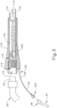
- FIG. 2 shows ablation catheter assembly (100) in greater detail.
- ablation catheter (120) extends distally from handle (110); while a fluid connector assembly (130) extends proximally from handle (110).
- position sensor (140), electrodes (150), and irrigation ports (160) are located at the distal end (122) of ablation catheter (120).
- Ablation catheter (120) of the present example is long and flexible and is sized to fit within various lumens and other passageways within the cardiovascular system of the patient (PA).
- position sensor (140) is operable to generate signals that are indicative of the position and orientation of distal end (122) within the patient (PA).
- position sensor (140) includes a wire coil or a plurality of wire coils (e.g., three coils) that are configured to generate electrical signals in response to the presence of an alternating electromagnetic field; or in response to movement within a static magnetic field.
- the two or more wire coils may be oriented along respective axes that are orthogonal to each other or have any other suitable relationship with each other.
- field generators (20) are operable to generate an alternating electromagnetic field, such that sensor (140) generates position indicative signals within the alternating electromagnetic field generated by field generators (20).
- Other techniques that may be used to generate real-time position data associated with distal end (122) may include wireless triangulation, acoustic tracking, optical tracking, inertial tracking, and the like.
- Some variations of ablation catheter assembly (100) may lack a position sensor (140).
- electrodes (150) may be configured to provide RF ablation or EP mapping functionality. Electrodes (150) may be configured and operable in accordance with the teachings of any of the various patent references that are cited herein. While only two electrodes (150) are shown in FIG. 2 , any suitable number of electrodes (150) may be provided. For instance, several pairs of electrodes (150) may be located at various positions along the length of ablation catheter (120). In some versions, electrodes (150) are configured to provide both RF ablation functionality and EP mapping functionality. In some other versions, electrodes (150) are configured to provide only RF ablation functionality without also providing EP mapping functionality. In still other versions, electrodes (150) are only configured to provide EP mapping functionality without also providing RF ablation functionality.
- ablation catheter (120) may include some electrodes (150) that are dedicated to providing only RF ablation functionality and other electrodes that are dedicated to providing only EP mapping functionality.
- Other suitable configurations and functionalities that may be associated with electrodes (150) will be apparent to those skilled in the art in view of the teachings herein.
- distal end (122) of ablation catheter (120) of the present example includes a set of irrigation ports (160), which are in the form of lateral openings on the exterior of ablation catheter (120). While only two irrigation ports (160) are shown in FIG. 2 , any suitable number of irrigation ports (160) may be provided. In the example shown in FIG. 2 , one irrigation port (160) is longitudinally interposed between electrodes (150) while another irrigation port (160) is distal to electrodes (150). Alternatively, irrigation ports (160) may be located at any other suitable positions on ablation catheter (120).
- Irrigation ports (160) receive irrigation fluid via an irrigation conduit (134) contained in fluid connector assembly (130), which extends proximally from handle (110) as noted above.
- fluid connector assembly (130) is configured to couple with fluid conduit (40).
- Fluid connector assembly (130) includes an outer sheath (132) and a fluid connector (200).
- outer sheath (132) is electrically insulative.
- outer sheath (132) may comprise a heat shrink wrap.
- An irrigation conduit (134) is disposed in outer sheath (132) and is in fluid communication with fluid connector (200).
- Irrigation conduit (134) comprises a flexible tubular body that extends along the length of ablation catheter (120) and is in fluid communication with irrigation ports (160), thereby providing a path for fluid communication from fluid connector (200) to irrigation ports (160).
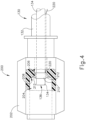
- fluid connector (200) of the present example comprises a body (202) defining a first passageway (204) and a second passageway (206), with a tapered transition (208) between passageways (204, 206).
- body (202) is configured as a first luer lock feature that is configured to mate with a second luer lock feature provided by a fluid connector (46) at the distal end of conduit (40).
- Fluid connectors (46, 200) are thus operable to selectively lock together and thereby provide a path for communication of irrigation fluid from conduit (40) and irrigation conduit (134).
- Luer lock features are just one merely illustrative example.
- Other suitable forms that body (202) and fluid connector (46) may take will be apparent to those skilled in the art in view of the teachings herein.
- irrigation conduit (134) is positioned within body (202) such that irrigation conduit (134) passes fully through second passageway (206), with the proximal end (136) of irrigation conduit (134) being positioned in first passageway (204). Irrigation conduit (134) is thus in fluid communication with first passageway (204).
- handle (110) includes a printed circuit board (PCB) (170) with various electrical components that are configured to provide the electrical functionalities described herein.
- PCB printed circuit board
- a set of wires (174) extend distally from PCB (170). Wires (174) extend along the length of ablation catheter (120) to position sensor (140) and electrodes (150), thereby providing a path for electrical communication between PCB (170) and position sensor (140); and between PCB (170) and electrodes (150).
- Another set of wires (172) extend proximally from PCB (170).
- Wires (172) extend to electrical contacts in an electrical interface (114), which is positioned within a socket (112) at the proximal end of handle (110). As shown in FIG. 3 , socket is configured to receive a plug (32) at the distal end of cable (30). Plug (32) includes electrical contacts that mate with the electrical contacts of electrical interface (114) when plug (32) is fully seated in socket (112). These mating contacts thereby provide a path for electrical communication between cable (30) and PCB (170).
- guidance and drive system (10) may tend to pick up a substantial amount of electrical noise in signals from electrodes (150). This may occur when electrodes (150) are used to apply RF ablation, when electrodes (150) are used to provide EP mapping, or when electrodes (150) are used for other purposes (e.g., diagnostic purposes, therapeutic purposes, or other purposes).
- Such electrical noise may be substantially reduced by providing an electrical ground to the fluid path of irrigation fluid flowing from fluid conduit (40) to irrigation ports (160). However, providing an electrical ground to the fluid path of irrigation fluid flowing from fluid conduit (40) to irrigation ports (160) may tend to present a risk of fluid leaks.
- ablation catheter assembly (100) includes a conductive cuff (210) and a wire (220) to provide an electrical ground to the irrigation fluid in the fluid path of irrigation fluid flowing from fluid conduit (40) to irrigation ports (160) via irrigation conduit (134).
- Conductive cuff (210) is formed of an electrically conductive material that is biocompatible and that resists degradation from the presence of irrigation fluid.
- conductive cuff (210) may be formed of platinum/iridium alloy, palladium/platinum alloy, or any other suitable conductive and biocompatible material(s).
- Conductive cuff (210) is fixedly and coaxially secured about the exterior of irrigation conduit (134), just distal to proximal end (136).
- conductive cuff (210) may be fixedly and coaxially secured about the exterior of irrigation conduit (134) via a friction/interference fit or via an adhesive, such as adhesive (212) described below.
- Conductive cuff (210) is also fixedly and coaxially secured relative to body (202) via an adhesive (212).
- adhesive (212) may comprise a biocompatible adhesive or polymer such as polyurethane.
- adhesive (212) is radially interposed between the exterior of conductive cuff (210) and the inner diameter of second passageway (206), thereby providing a fluid tight seal between the exterior of conductive cuff (210) and the inner diameter of second passageway (206).
- a portion of adhesive (212) is also disposed along tapered transition (208), though this is merely optional.
- At least some adhesive (212) may also be radially interposed between the exterior of irrigation conduit (134) and the inner diameter of second passageway (206); or between the exterior of irrigation conduit (134) and tapered transition (208). In some instances, adhesive (212) is applied in a succession of layers to minimize the risk of fluid leakage between the exterior of irrigation conduit (134) and the inner diameter of second passageway (206). In the present example, the proximal end of conductive cuff (210) is left exposed by adhesive (212), such that conductive cuff (210) will be in electrical communication with any fluid that is present in firs passageway (206) of fluid connector (200).
- Wire (220) is secured to conductive cuff (210) and is thereby in electrical communication with conductive cuff (210).
- wire (220) may be secured to conductive cuff (210) via resistance or laser-based welding.
- wire (220) extends distally from conductive cuff (210), through second passageway (206) alongside irrigation conduit (134).
- wire (220) also extends through fluid connector assembly (130), within outer sheath (132) alongside irrigation conduit (134), eventually exiting outer sheath (132) transversely to reach PCB (170). The distal end of wire (220) is coupled with an electrical ground on PCB (170).
- the electrical ground on PCB (170) may be coupled with an electrical ground in console (12) via cable (30), such that PCP (170) and cable (30) provide a path for electrically grounding wire (220) to the electrical ground in console (12).
- PCB (170) may also include resistors, filters, or other components that are configured to provide additional safety and performance characteristics associated with the electrical grounding functionality provided by conductive cuff (210) and wire (220).
- a diode or an array of diodes may be placed in the electrical path to the grounding wire (220) to protect against electrostatic discharge.
- wire (220) is electrically grounded via PCB (170) in the present example
- wire (220) may instead be electrically grounded in any other suitable fashion.
- wire (220) may be directly coupled to a ground path in electrical interface (114) of socket (112), such that wire (220) bypasses PCB (170).
- Other suitable alternative ground paths for wire (220) will be apparent to those skilled in the art in view of the teachings herein.
- wire (220) is fluidly isolated from the fluid path of irrigation fluid flowing from fluid conduit (40) to irrigation ports (160), by virtue of adhesive (212).
- the irrigation fluid is saline, which contains electrolytes
- the irrigation fluid is capable of conducting electricity.
- wire (220) is in electrical communication with irrigation fluid flowing from fluid conduit (40) to irrigation ports (160), by virtue of wire (220) being coupled with conductive cuff (210). Cuff (210) and wire (220) thus cooperate to provide an electrical ground to irrigation fluid flowing from fluid conduit (40) to irrigation ports (160) via irrigation conduit (134).
- conductive cuff (210), wire (220), body (202), and irrigation conduit (134) may provide a substantially robust assembly that is relatively easy and inexpensive to manufacture; and that provides a relatively high degree of reliability.
- conductive cuff (210) is somehow decoupled from the exterior of irrigation conduit (134) and from the inner diameter of second passageway (206), conductive cuff (210) will not be able to pass through irrigation conduit (134) and thereby reach irrigation ports (160) since the outer diameter of conductive cuff (210) is greater than the inner diameter of irrigation conduit (134).
- the electrical grounding provided by cuff (210) and wire (220) may provide a safety feature by creating a patient ground that prevents stray electricity from going into the body of the patient (PA).
- the electrical grounding provided by cuff (210) and wire (220) may provide performance enhancement by minimizing electrocardiography (ECG) noise in the electrical signals from electrodes (150).
- conductive cuff (210) is positioned within fluid connector (200) in the present example, near the proximal end (136) of irrigation conduit (134), conductive cuff (210) or some other conductive grounding component may instead be placed near distal end (122) of ablation catheter (120).
- conductive cuff (210) or some other conductive grounding component may be reduced in size and positioned within the lumen of irrigation conduit (134), near distal end (122) or elsewhere along the length of irrigation conduit (134).
- wire (220) may be repositioned to maintain electrical continuity between conductive cuff (210) (or the variation thereof) and the electrical grounding portion of PCB (170).
- conductive cuff (210) is in the form of an annular cuff in the present example
- any other suitable configuration may be used to provide an electrical ground to the irrigation fluid flowing from fluid conduit (40) to irrigation ports (160) via irrigation conduit (134).
- a grounding member in the form of a conductive rod, conductive stem, conductive strip, or other shape of conductive structure may be radially interposed between the exterior of irrigation conduit (134) and the inner diameter of second passageway (206), with adhesive (212) being used to secure the grounding member in place while also fluidly sealing the rest of the space between the exterior of irrigation conduit (134) and the inner diameter of second passageway (206).
- Such an alternative grounding member may be oriented parallel with the longitudinal axis shared by irrigation conduit (134) and second passageway (206), while still being laterally offset from the longitudinal axis shared by irrigation conduit (134) and second passageway (206).
Landscapes
- Health & Medical Sciences (AREA)
- Life Sciences & Earth Sciences (AREA)
- Engineering & Computer Science (AREA)
- Surgery (AREA)
- General Health & Medical Sciences (AREA)
- Public Health (AREA)
- Animal Behavior & Ethology (AREA)
- Veterinary Medicine (AREA)
- Physics & Mathematics (AREA)
- Biomedical Technology (AREA)
- Heart & Thoracic Surgery (AREA)
- Medical Informatics (AREA)
- Molecular Biology (AREA)
- Biophysics (AREA)
- Pathology (AREA)
- Nuclear Medicine, Radiotherapy & Molecular Imaging (AREA)
- Plasma & Fusion (AREA)
- Otolaryngology (AREA)
- Cardiology (AREA)
- Signal Processing (AREA)
- Physiology (AREA)
- Human Computer Interaction (AREA)
- Radiology & Medical Imaging (AREA)
- Artificial Intelligence (AREA)
- Computer Vision & Pattern Recognition (AREA)
- Psychiatry (AREA)
- Surgical Instruments (AREA)
Claims (14)
- Appareil (100), comprenant :(a) un corps (110) ; et(b) un cathéter (120) s'étendant distalement depuis le corps (110), dans lequel au moins une partie du cathéter est dimensionnée et configurée pour aller à l'intérieur d'une lumière d'un système cardiovasculaire humain, dans lequel le cathéter (120) inclut :caractérisé en ce que :(i) une extrémité distale (122),(ii) une extrémité proximale,(iii) au moins une électrode (150) à l'extrémité distale,(iv) au moins un orifice d'irrigation (160) à l'extrémité distale, et(v) un conduit de fluide (134) en communication fluidique avec l'au moins un orifice d'irrigation (160) ;l'appareil comprend en outre :
(c) un ensemble à raccord fluidique (200) s'étendant proximalement depuis le corps (110), dans lequel l'ensemble à raccord fluidique (200) comprend :(i) un corps de raccord fluidique (202), dans lequel le corps de raccord fluidique (202) est configuré pour s'accoupler avec un raccord complémentaire associé à une source de fluide (42), dans lequel une extrémité proximale du conduit de fluide (134) est positionnée dans une région intérieure du corps de raccord fluidique (202),(ii) un élément de mise à la terre (210) interposé entre l'extrémité proximale du conduit de fluide (134) et le corps de raccord fluidique (202), dans lequel l'élément de mise à la terre (210) est en communication avec la région intérieure du corps de raccord fluidique (202) de telle sorte que l'élément de mise à la terre (210) soit configuré pour fournir une mise électrique à la terre à un fluide transmis au conduit de fluide (134) par l'intermédiaire du corps de raccord fluidique (202), etl'élément de mise à la terre (210) comprend un manchon conducteur qui est coaxialement positionné autour de l'extrémité proximale du conduit de fluide (134) et est fixé au corps de raccord fluidique (202) par un adhésif (212), l'adhésif étant interposé entre un extérieur du manchon conducteur (210) et une partie intérieure du corps de raccord fluidique (202), de telle sorte qu'une partie du manchon conducteur soit positionnée pour l'exposition à un fluide transmis à travers le conduit de fluide (134). - Appareil selon la revendication 1, dans lequel l'au moins une électrode (150) est configurée pour appliquer de l'énergie RF sur un tissu.
- Appareil selon la revendication 1, dans lequel l'au moins une électrode (150) est configurée pour capter des signaux associés à une cartographie électrophysiologique (EP) à l'intérieur d'un système cardiovasculaire humain.
- Appareil selon la revendication 3, dans lequel l'élément de mise à la terre (210) est configuré pour réduire le bruit dans des signaux de cartographie EP provenant de l'au moins un électrode (150).
- Appareil selon la revendication 1, dans lequel le manchon conducteur (210) comprend un alliage platine/iridium, alliage palladium/platine, ou un autre matériau hautement conducteur et biocompatible.
- Appareil selon la revendication 1, dans lequel la région intérieure du corps de raccord fluidique (202) comprend une première partie ayant un premier diamètre intérieur et une seconde partie ayant un second diamètre intérieur, dans lequel le premier diamètre intérieur est supérieur au second diamètre intérieur, dans lequel l'extrémité proximale du conduit de fluide (134) se termine à l'intérieur de la première partie de la région intérieure, dans lequel l'élément de mise à la terre (210) est fixé à la seconde partie de la région intérieure.
- Appareil selon la revendication 1, dans lequel le corps (110) de l'appareil (100) inclut un circuit électrique (170) ayant une mise électrique à la terre, dans lequel l'élément de mise à la terre (210) est en communication électrique avec la mise électrique à la terre du circuit électrique (170) dans le corps (110) de l'appareil (100).
- Appareil selon la revendication 7, comprenant en outre un fil métallique (220) s'étendant entre la mise électrique à la terre du circuit électrique (170) et l'élément de mise à la terre (210).
- Appareil selon la revendication 8, dans lequel le fil métallique (220) est fluidiquement isolé de la région intérieure du corps de raccord fluidique (202).
- Appareil selon la revendication 7, comprenant en outre :(a) un câble (30), dans lequel le câble est couplé au corps ; et(b) une unité console (12), dans lequel le câble (30) est en outre couplé à l'unité console (12), dans lequel l'unité console (12) a une mise électrique à la terre, dans lequel le câble (30) est configuré pour fournir un chemin électrique entre la mise électrique à la terre du circuit électrique dans le corps (110) et la mise électrique à la terre de l'unité console (12).
- Appareil selon la revendication 10, dans lequel l'unité console (12) est en outre configurée pour fournir de l'énergie RF à l'au moins une électrode (150) par l'intermédiaire du câble (30).
- Appareil selon la revendication 10, dans lequel l'unité console est en outre configurée pour recevoir et traiter des signaux de cartographie EP provenant de l'au moins une électrode (150) par l'intermédiaire du câble (30).
- Appareil selon la revendication 10, dans lequel le cathéter (120) inclut en outre un capteur de position (140) utilisable pour générer des signaux indiquant une position de l'extrémité distale dans un espace tridimensionnel, dans lequel l'unité console (12) est en outre configurée pour recevoir et traiter les signaux provenant du capteur de position, optionnellement dans lequel :
l'appareil comprend en outre un ou plusieurs générateurs de champ magnétique (20), dans lequel l'un ou les plusieurs générateurs de champ magnétique (20) sont configurés pour générer un champ magnétique autour d'au moins une partie d'un patient, dans lequel le capteur de position (140) est configuré pour générer des signaux en réponse au champ magnétique généré, et en outre optionnellement dans lequel :
l'unité console (12) est couplée à l'un ou aux plusieurs générateurs de champ magnétique (20) par l'intermédiaire d'un ou de plusieurs câbles (22), dans lequel l'unité console (12) est utilisable pour exciter l'un ou les plusieurs générateurs de champ magnétique (20) pour générer le champ magnétique. - Appareil selon la revendication 1, dans lequel l'extrémité proximale du conduit de fluide (134) et la région intérieure sont coaxialement alignées le long d'un axe commun, et
dans lequel l'élément de mise à la terre (210) est positionné dans la région intérieure, et orienté coaxialement avec, ou parallèlement à, l'axe commun.
Applications Claiming Priority (2)
| Application Number | Priority Date | Filing Date | Title |
|---|---|---|---|
| US16/014,130 US11154357B2 (en) | 2018-06-21 | 2018-06-21 | Electrical grounding feature for irrigation fluid path in catheter assembly |
| PCT/IB2019/055058 WO2019244009A1 (fr) | 2018-06-21 | 2019-06-17 | Élément de mise à la terre électrique pour trajet de fluide d'irrigation dans un ensemble cathéter |
Publications (3)
| Publication Number | Publication Date |
|---|---|
| EP3810004A1 EP3810004A1 (fr) | 2021-04-28 |
| EP3810004C0 EP3810004C0 (fr) | 2023-08-09 |
| EP3810004B1 true EP3810004B1 (fr) | 2023-08-09 |
Family
ID=67770540
Family Applications (1)
| Application Number | Title | Priority Date | Filing Date |
|---|---|---|---|
| EP19759429.4A Active EP3810004B1 (fr) | 2018-06-21 | 2019-06-17 | Élément de mise à la terre électrique pour trajet de fluide d'irrigation dans un ensemble cathéter |
Country Status (6)
| Country | Link |
|---|---|
| US (1) | US11154357B2 (fr) |
| EP (1) | EP3810004B1 (fr) |
| JP (1) | JP7472045B2 (fr) |
| CN (1) | CN112312854B (fr) |
| IL (1) | IL279518B2 (fr) |
| WO (1) | WO2019244009A1 (fr) |
Families Citing this family (3)
| Publication number | Priority date | Publication date | Assignee | Title |
|---|---|---|---|---|
| US10278789B2 (en) | 2013-03-14 | 2019-05-07 | National Dentex, Llc | Bone foundation guide system and method |
| WO2017155823A1 (fr) | 2016-03-05 | 2017-09-14 | National Dentex, Llc | Procédé et système de guide de fondation osseuse |
| CN115137466A (zh) * | 2022-07-11 | 2022-10-04 | 洲瓴(上海)医疗器械有限公司 | 一种脉冲电场消融用电极导管 |
Family Cites Families (21)
| Publication number | Priority date | Publication date | Assignee | Title |
|---|---|---|---|---|
| US5738096A (en) | 1993-07-20 | 1998-04-14 | Biosense, Inc. | Cardiac electromechanics |
| JP3649862B2 (ja) * | 1997-06-23 | 2005-05-18 | 本田技研工業株式会社 | 燃料用配管構造 |
| US20050228367A1 (en) * | 1999-01-25 | 2005-10-13 | Marwan Abboud | Leak detection system for catheter based medical device |
| US8915842B2 (en) * | 2008-07-14 | 2014-12-23 | Ethicon Endo-Surgery, Inc. | Methods and devices for maintaining visibility and providing irrigation and/or suction during surgical procedures |
| US9987025B2 (en) * | 2006-05-26 | 2018-06-05 | Bruce B. Becker | Increased axial load carrying sheathed irrigating balloon catheter |
| CA2798020C (fr) * | 2010-05-19 | 2015-06-30 | Tangent Medical Technologies, Inc. | Systeme d'administration vasculaire integre avec aiguille de securite |
| US20120165735A1 (en) * | 2010-12-28 | 2012-06-28 | Sandra Keh | Devices and Methods for Reducing Electrical Noise in an Irrigated Electrophysiology Catheter System |
| US10743932B2 (en) * | 2011-07-28 | 2020-08-18 | Biosense Webster (Israel) Ltd. | Integrated ablation system using catheter with multiple irrigation lumens |
| US8956353B2 (en) | 2011-12-29 | 2015-02-17 | Biosense Webster (Israel) Ltd. | Electrode irrigation using micro-jets |
| CN104869883B (zh) * | 2012-10-23 | 2018-07-27 | 波士顿科学国际有限公司 | 与医疗器械一起使用的信号传输组件 |
| US10265025B2 (en) | 2013-06-25 | 2019-04-23 | Biosense Webster (Israel) Ltd. | Electrocardiogram noise reduction |
| US9504522B2 (en) * | 2013-06-25 | 2016-11-29 | Biosense Webster (Israel) Ltd. | Electrocardiogram noise reduction |
| CA3190740A1 (fr) * | 2014-03-24 | 2015-10-01 | Boston Scientific Medical Device Limited | Appareil medical pour la communication de fluide |
| US9788893B2 (en) | 2014-11-20 | 2017-10-17 | Biosense Webster (Israel) Ltd. | Catheter with soft distal tip for mapping and ablating tubular region |
| US9801585B2 (en) * | 2014-12-31 | 2017-10-31 | Biosense Webster (Israel) Ltd. | Electrocardiogram noise reduction |
| US10363090B2 (en) * | 2016-01-05 | 2019-07-30 | Biosense Webster (Israel) Ltd. | Catheter with flow diverter and force sensor |
| US9907480B2 (en) | 2016-02-08 | 2018-03-06 | Biosense Webster (Israel) Ltd. | Catheter spine assembly with closely-spaced bipole microelectrodes |
| US11134899B2 (en) | 2016-05-06 | 2021-10-05 | Biosense Webster (Israel) Ltd. | Catheter with shunting electrode |
| US10702177B2 (en) | 2016-08-24 | 2020-07-07 | Biosense Webster (Israel) Ltd. | Catheter with bipole electrode spacer and related methods |
| US11559349B2 (en) | 2016-09-12 | 2023-01-24 | Biosense Webster (Israel) Ltd. | Ablation catheter with a flexible printed circuit board |
| US10485609B2 (en) * | 2016-10-18 | 2019-11-26 | Acclarent, Inc. | Dilation balloon with RF energy delivery feature |
-
2018
- 2018-06-21 US US16/014,130 patent/US11154357B2/en active Active
-
2019
- 2019-06-17 CN CN201980041758.0A patent/CN112312854B/zh active Active
- 2019-06-17 WO PCT/IB2019/055058 patent/WO2019244009A1/fr not_active Ceased
- 2019-06-17 JP JP2020570904A patent/JP7472045B2/ja active Active
- 2019-06-17 IL IL279518A patent/IL279518B2/en unknown
- 2019-06-17 EP EP19759429.4A patent/EP3810004B1/fr active Active
Also Published As
| Publication number | Publication date |
|---|---|
| IL279518A (en) | 2021-01-31 |
| CN112312854A (zh) | 2021-02-02 |
| CN112312854B (zh) | 2024-09-24 |
| IL279518B1 (en) | 2023-09-01 |
| EP3810004A1 (fr) | 2021-04-28 |
| US20190388148A1 (en) | 2019-12-26 |
| EP3810004C0 (fr) | 2023-08-09 |
| JP7472045B2 (ja) | 2024-04-22 |
| IL279518B2 (en) | 2024-01-01 |
| US11154357B2 (en) | 2021-10-26 |
| WO2019244009A1 (fr) | 2019-12-26 |
| JP2021527526A (ja) | 2021-10-14 |
Similar Documents
| Publication | Publication Date | Title |
|---|---|---|
| EP3915501B1 (fr) | Électrode de référence intraluminale pour appareil de traitement cardiovasculaire | |
| US20210077184A1 (en) | Catheter with thin-film electrodes on expandable membrane | |
| US20210369132A1 (en) | Intraluminal reference electrode for cardiovascular treatment apparatus | |
| EP4048178B1 (fr) | Cathéter de cartographie cardiaque doté d'électrodes à espacement carré | |
| US20230200895A1 (en) | Catheter end effector with resilient frame and flexible interior | |
| WO2021053482A1 (fr) | Instrument de cathéter à trois fils de traction | |
| EP3586737B1 (fr) | Fils de référence pour éliminer le bruit et les artéfacts dans un cathéter de cartographie cardiaque | |
| US20230190367A1 (en) | Catheter end effector with laterally projecting body | |
| US20240245359A1 (en) | Catheter with insert-molded microelectrode | |
| EP3810004B1 (fr) | Élément de mise à la terre électrique pour trajet de fluide d'irrigation dans un ensemble cathéter | |
| EP4360577A1 (fr) | Tubulure d'irrigation à émission de fluide régulée | |
| US12611263B2 (en) | Modular steerable sheath and catheter | |
| US20230310071A1 (en) | Catheter with external magnetic coils | |
| EP4342405B1 (fr) | Tige de cathéter avec articulation et rotation multi-plans |
Legal Events
| Date | Code | Title | Description |
|---|---|---|---|
| STAA | Information on the status of an ep patent application or granted ep patent |
Free format text: STATUS: UNKNOWN |
|
| STAA | Information on the status of an ep patent application or granted ep patent |
Free format text: STATUS: THE INTERNATIONAL PUBLICATION HAS BEEN MADE |
|
| PUAI | Public reference made under article 153(3) epc to a published international application that has entered the european phase |
Free format text: ORIGINAL CODE: 0009012 |
|
| STAA | Information on the status of an ep patent application or granted ep patent |
Free format text: STATUS: REQUEST FOR EXAMINATION WAS MADE |
|
| 17P | Request for examination filed |
Effective date: 20210108 |
|
| AK | Designated contracting states |
Kind code of ref document: A1 Designated state(s): AL AT BE BG CH CY CZ DE DK EE ES FI FR GB GR HR HU IE IS IT LI LT LU LV MC MK MT NL NO PL PT RO RS SE SI SK SM TR |
|
| AX | Request for extension of the european patent |
Extension state: BA ME |
|
| DAV | Request for validation of the european patent (deleted) | ||
| DAX | Request for extension of the european patent (deleted) | ||
| RAP3 | Party data changed (applicant data changed or rights of an application transferred) |
Owner name: BIOSENSE WEBSTER (ISRAEL) LTD. |
|
| RAP3 | Party data changed (applicant data changed or rights of an application transferred) |
Owner name: BIOSENSE WEBSTER (ISRAEL) LTD. |
|
| GRAP | Despatch of communication of intention to grant a patent |
Free format text: ORIGINAL CODE: EPIDOSNIGR1 |
|
| STAA | Information on the status of an ep patent application or granted ep patent |
Free format text: STATUS: GRANT OF PATENT IS INTENDED |
|
| INTG | Intention to grant announced |
Effective date: 20230102 |
|
| GRAJ | Information related to disapproval of communication of intention to grant by the applicant or resumption of examination proceedings by the epo deleted |
Free format text: ORIGINAL CODE: EPIDOSDIGR1 |
|
| STAA | Information on the status of an ep patent application or granted ep patent |
Free format text: STATUS: REQUEST FOR EXAMINATION WAS MADE |
|
| GRAP | Despatch of communication of intention to grant a patent |
Free format text: ORIGINAL CODE: EPIDOSNIGR1 |
|
| STAA | Information on the status of an ep patent application or granted ep patent |
Free format text: STATUS: GRANT OF PATENT IS INTENDED |
|
| INTC | Intention to grant announced (deleted) | ||
| GRAS | Grant fee paid |
Free format text: ORIGINAL CODE: EPIDOSNIGR3 |
|
| INTG | Intention to grant announced |
Effective date: 20230601 |
|
| GRAA | (expected) grant |
Free format text: ORIGINAL CODE: 0009210 |
|
| STAA | Information on the status of an ep patent application or granted ep patent |
Free format text: STATUS: THE PATENT HAS BEEN GRANTED |
|
| AK | Designated contracting states |
Kind code of ref document: B1 Designated state(s): AL AT BE BG CH CY CZ DE DK EE ES FI FR GB GR HR HU IE IS IT LI LT LU LV MC MK MT NL NO PL PT RO RS SE SI SK SM TR |
|
| REG | Reference to a national code |
Ref country code: GB Ref legal event code: FG4D |
|
| REG | Reference to a national code |
Ref country code: CH Ref legal event code: EP |
|
| REG | Reference to a national code |
Ref country code: DE Ref legal event code: R096 Ref document number: 602019034639 Country of ref document: DE |
|
| REG | Reference to a national code |
Ref country code: IE Ref legal event code: FG4D |
|
| U01 | Request for unitary effect filed |
Effective date: 20230911 |
|
| U07 | Unitary effect registered |
Designated state(s): AT BE BG DE DK EE FI FR IT LT LU LV MT NL PT SE SI Effective date: 20230914 |
|
| PG25 | Lapsed in a contracting state [announced via postgrant information from national office to epo] |
Ref country code: GR Free format text: LAPSE BECAUSE OF FAILURE TO SUBMIT A TRANSLATION OF THE DESCRIPTION OR TO PAY THE FEE WITHIN THE PRESCRIBED TIME-LIMIT Effective date: 20231110 |
|
| PG25 | Lapsed in a contracting state [announced via postgrant information from national office to epo] |
Ref country code: IS Free format text: LAPSE BECAUSE OF FAILURE TO SUBMIT A TRANSLATION OF THE DESCRIPTION OR TO PAY THE FEE WITHIN THE PRESCRIBED TIME-LIMIT Effective date: 20231209 |
|
| PG25 | Lapsed in a contracting state [announced via postgrant information from national office to epo] |
Ref country code: RS Free format text: LAPSE BECAUSE OF FAILURE TO SUBMIT A TRANSLATION OF THE DESCRIPTION OR TO PAY THE FEE WITHIN THE PRESCRIBED TIME-LIMIT Effective date: 20230809 Ref country code: NO Free format text: LAPSE BECAUSE OF FAILURE TO SUBMIT A TRANSLATION OF THE DESCRIPTION OR TO PAY THE FEE WITHIN THE PRESCRIBED TIME-LIMIT Effective date: 20231109 Ref country code: IS Free format text: LAPSE BECAUSE OF FAILURE TO SUBMIT A TRANSLATION OF THE DESCRIPTION OR TO PAY THE FEE WITHIN THE PRESCRIBED TIME-LIMIT Effective date: 20231209 Ref country code: HR Free format text: LAPSE BECAUSE OF FAILURE TO SUBMIT A TRANSLATION OF THE DESCRIPTION OR TO PAY THE FEE WITHIN THE PRESCRIBED TIME-LIMIT Effective date: 20230809 Ref country code: GR Free format text: LAPSE BECAUSE OF FAILURE TO SUBMIT A TRANSLATION OF THE DESCRIPTION OR TO PAY THE FEE WITHIN THE PRESCRIBED TIME-LIMIT Effective date: 20231110 |
|
| PG25 | Lapsed in a contracting state [announced via postgrant information from national office to epo] |
Ref country code: PL Free format text: LAPSE BECAUSE OF FAILURE TO SUBMIT A TRANSLATION OF THE DESCRIPTION OR TO PAY THE FEE WITHIN THE PRESCRIBED TIME-LIMIT Effective date: 20230809 |
|
| PG25 | Lapsed in a contracting state [announced via postgrant information from national office to epo] |
Ref country code: ES Free format text: LAPSE BECAUSE OF FAILURE TO SUBMIT A TRANSLATION OF THE DESCRIPTION OR TO PAY THE FEE WITHIN THE PRESCRIBED TIME-LIMIT Effective date: 20230809 |
|
| PG25 | Lapsed in a contracting state [announced via postgrant information from national office to epo] |
Ref country code: SM Free format text: LAPSE BECAUSE OF FAILURE TO SUBMIT A TRANSLATION OF THE DESCRIPTION OR TO PAY THE FEE WITHIN THE PRESCRIBED TIME-LIMIT Effective date: 20230809 Ref country code: RO Free format text: LAPSE BECAUSE OF FAILURE TO SUBMIT A TRANSLATION OF THE DESCRIPTION OR TO PAY THE FEE WITHIN THE PRESCRIBED TIME-LIMIT Effective date: 20230809 Ref country code: ES Free format text: LAPSE BECAUSE OF FAILURE TO SUBMIT A TRANSLATION OF THE DESCRIPTION OR TO PAY THE FEE WITHIN THE PRESCRIBED TIME-LIMIT Effective date: 20230809 Ref country code: CZ Free format text: LAPSE BECAUSE OF FAILURE TO SUBMIT A TRANSLATION OF THE DESCRIPTION OR TO PAY THE FEE WITHIN THE PRESCRIBED TIME-LIMIT Effective date: 20230809 Ref country code: SK Free format text: LAPSE BECAUSE OF FAILURE TO SUBMIT A TRANSLATION OF THE DESCRIPTION OR TO PAY THE FEE WITHIN THE PRESCRIBED TIME-LIMIT Effective date: 20230809 |
|
| REG | Reference to a national code |
Ref country code: DE Ref legal event code: R097 Ref document number: 602019034639 Country of ref document: DE |
|
| U20 | Renewal fee for the european patent with unitary effect paid |
Year of fee payment: 6 Effective date: 20240509 |
|
| PLBE | No opposition filed within time limit |
Free format text: ORIGINAL CODE: 0009261 |
|
| STAA | Information on the status of an ep patent application or granted ep patent |
Free format text: STATUS: NO OPPOSITION FILED WITHIN TIME LIMIT |
|
| 26N | No opposition filed |
Effective date: 20240513 |
|
| PG25 | Lapsed in a contracting state [announced via postgrant information from national office to epo] |
Ref country code: MC Free format text: LAPSE BECAUSE OF FAILURE TO SUBMIT A TRANSLATION OF THE DESCRIPTION OR TO PAY THE FEE WITHIN THE PRESCRIBED TIME-LIMIT Effective date: 20230809 |
|
| REG | Reference to a national code |
Ref country code: CH Ref legal event code: PL |
|
| PG25 | Lapsed in a contracting state [announced via postgrant information from national office to epo] |
Ref country code: IE Free format text: LAPSE BECAUSE OF NON-PAYMENT OF DUE FEES Effective date: 20240617 |
|
| PG25 | Lapsed in a contracting state [announced via postgrant information from national office to epo] |
Ref country code: CH Free format text: LAPSE BECAUSE OF NON-PAYMENT OF DUE FEES Effective date: 20240630 |
|
| U20 | Renewal fee for the european patent with unitary effect paid |
Year of fee payment: 7 Effective date: 20250509 |
|
| PGFP | Annual fee paid to national office [announced via postgrant information from national office to epo] |
Ref country code: GB Payment date: 20250501 Year of fee payment: 7 |
|
| PG25 | Lapsed in a contracting state [announced via postgrant information from national office to epo] |
Ref country code: CY Free format text: LAPSE BECAUSE OF FAILURE TO SUBMIT A TRANSLATION OF THE DESCRIPTION OR TO PAY THE FEE WITHIN THE PRESCRIBED TIME-LIMIT; INVALID AB INITIO Effective date: 20190617 |
|
| PG25 | Lapsed in a contracting state [announced via postgrant information from national office to epo] |
Ref country code: HU Free format text: LAPSE BECAUSE OF FAILURE TO SUBMIT A TRANSLATION OF THE DESCRIPTION OR TO PAY THE FEE WITHIN THE PRESCRIBED TIME-LIMIT; INVALID AB INITIO Effective date: 20190617 |