EP3810254B1 - Ensemble raccord destiné à raccorder des tuyaux médicaux comprenant un élément de recouvrement - Google Patents
Ensemble raccord destiné à raccorder des tuyaux médicaux comprenant un élément de recouvrement Download PDFInfo
- Publication number
- EP3810254B1 EP3810254B1 EP19727017.6A EP19727017A EP3810254B1 EP 3810254 B1 EP3810254 B1 EP 3810254B1 EP 19727017 A EP19727017 A EP 19727017A EP 3810254 B1 EP3810254 B1 EP 3810254B1
- Authority
- EP
- European Patent Office
- Prior art keywords
- connector
- retention device
- cap element
- connector assembly
- assembly according
- Prior art date
- Legal status (The legal status is an assumption and is not a legal conclusion. Google has not performed a legal analysis and makes no representation as to the accuracy of the status listed.)
- Active
Links
Images

Classifications
-
- A—HUMAN NECESSITIES
- A61—MEDICAL OR VETERINARY SCIENCE; HYGIENE
- A61M—DEVICES FOR INTRODUCING MEDIA INTO, OR ONTO, THE BODY; DEVICES FOR TRANSDUCING BODY MEDIA OR FOR TAKING MEDIA FROM THE BODY; DEVICES FOR PRODUCING OR ENDING SLEEP OR STUPOR
- A61M39/00—Tubes, tube connectors, tube couplings, valves, access sites or the like, specially adapted for medical use
- A61M39/20—Closure caps or plugs for connectors or open ends of tubes
-
- A—HUMAN NECESSITIES
- A61—MEDICAL OR VETERINARY SCIENCE; HYGIENE
- A61M—DEVICES FOR INTRODUCING MEDIA INTO, OR ONTO, THE BODY; DEVICES FOR TRANSDUCING BODY MEDIA OR FOR TAKING MEDIA FROM THE BODY; DEVICES FOR PRODUCING OR ENDING SLEEP OR STUPOR
- A61M39/00—Tubes, tube connectors, tube couplings, valves, access sites or the like, specially adapted for medical use
- A61M39/10—Tube connectors; Tube couplings
-
- A—HUMAN NECESSITIES
- A61—MEDICAL OR VETERINARY SCIENCE; HYGIENE
- A61M—DEVICES FOR INTRODUCING MEDIA INTO, OR ONTO, THE BODY; DEVICES FOR TRANSDUCING BODY MEDIA OR FOR TAKING MEDIA FROM THE BODY; DEVICES FOR PRODUCING OR ENDING SLEEP OR STUPOR
- A61M39/00—Tubes, tube connectors, tube couplings, valves, access sites or the like, specially adapted for medical use
- A61M39/10—Tube connectors; Tube couplings
- A61M39/1011—Locking means for securing connection; Additional tamper safeties
-
- A—HUMAN NECESSITIES
- A61—MEDICAL OR VETERINARY SCIENCE; HYGIENE
- A61M—DEVICES FOR INTRODUCING MEDIA INTO, OR ONTO, THE BODY; DEVICES FOR TRANSDUCING BODY MEDIA OR FOR TAKING MEDIA FROM THE BODY; DEVICES FOR PRODUCING OR ENDING SLEEP OR STUPOR
- A61M5/00—Devices for bringing media into the body in a subcutaneous, intra-vascular or intramuscular way; Accessories therefor, e.g. filling or cleaning devices, arm-rests
- A61M5/178—Syringes
- A61M5/31—Details
- A61M2005/3103—Leak prevention means for distal end of syringes, i.e. syringe end for mounting a needle
- A61M2005/3104—Caps for syringes without needle
-
- A—HUMAN NECESSITIES
- A61—MEDICAL OR VETERINARY SCIENCE; HYGIENE
- A61M—DEVICES FOR INTRODUCING MEDIA INTO, OR ONTO, THE BODY; DEVICES FOR TRANSDUCING BODY MEDIA OR FOR TAKING MEDIA FROM THE BODY; DEVICES FOR PRODUCING OR ENDING SLEEP OR STUPOR
- A61M5/00—Devices for bringing media into the body in a subcutaneous, intra-vascular or intramuscular way; Accessories therefor, e.g. filling or cleaning devices, arm-rests
- A61M5/178—Syringes
- A61M5/31—Details
- A61M2005/3103—Leak prevention means for distal end of syringes, i.e. syringe end for mounting a needle
- A61M2005/3106—Plugs for syringes without needle
-
- A—HUMAN NECESSITIES
- A61—MEDICAL OR VETERINARY SCIENCE; HYGIENE
- A61M—DEVICES FOR INTRODUCING MEDIA INTO, OR ONTO, THE BODY; DEVICES FOR TRANSDUCING BODY MEDIA OR FOR TAKING MEDIA FROM THE BODY; DEVICES FOR PRODUCING OR ENDING SLEEP OR STUPOR
- A61M39/00—Tubes, tube connectors, tube couplings, valves, access sites or the like, specially adapted for medical use
- A61M39/10—Tube connectors; Tube couplings
- A61M2039/1038—Union screw connectors, e.g. hollow screw or sleeve having external threads
Definitions
- the invention relates to a connector assembly for connecting medical lines to each other according to the preamble of claim 1.
- the invention is defined in claim 1. Further embodiments of the invention are defined in the dependent claims.
- a connector assembly of this kind comprises a first connector having an insertion shaft to be inserted, along an insertion direction, into an insertion opening of a second connector for forming a fluid connection between the medical lines, the insertion shaft comprising a fluid channel allowing fluid to flow in between the first connector and the second connector when the first connector and the second connector are attached to each other.
- a medical line of this kind may for example be a line used for the enteral feeding of a patient.
- Enteral feeding generally refers to the delivery of a nutritionally complete feed, containing protein, carbohydrate, fat, water, minerals and vitamins, directly into the stomach, duodenum or jejunum of a patient.
- a feeding tube for this purpose, may for example be passed through the nares (nostril), down the esophagus and into the stomach (so-called nasogastric feeding tube).
- a nasojejunal feeding tube in comparison, may be passed further through the stomach into the jejunum, the middle section of the small intestine.
- a gastric feeding tube is a tube inserted through a small incision in the abdomen into the stomach and is used, preferably, for long-term enteral nutrition.
- a first line may for example be placed on the patient, for example providing a feeding port to the stomach. This first line may remain on the patient for a rather long time, for example a few days or even a few weeks.
- Another, second line may be connected to this first line for the actual feeding wherein for each feeding procedure a new second line may be used and disposed after the feeding procedure.
- a connector assembly in this example serves to connect the feeding lines to each other.
- a first connector also denoted as male connector, for example a so-called ENFit male connector
- a second connector female connector, for example a so-called ENFit female connector
- the second connector may be used only once for carrying out a feeding procedure
- the first connector connected for example to a line placed on a patient may be re-used multiple times. Because the first connector may be re-used multiple times for multiple feeding procedures, it is to be made sure that the first connector is clean when connecting the lines to each other, in order to avoid a contamination of any solution passed towards the patient. Furthermore, no fluid carried out of the first connector if it is not connected to a corresponding second connector.
- a connector assembly comprising a first connector and a cap element is disclosed.
- the first connector is a male connector having an outer locking collar and an internal tapered sealing wall.
- the cap element is configured to receive a tapered sealing wall of the male connector so as to form a seal with an outer surface of the tapered sealing wall.
- the connector assembly comprises a cap element attachable to the first connector for closing the fluid channel towards the outside in a state in which the first connector is not connected to the second connector, the first connector having a first retention device and the cap element having a second retention device, the first retention device and the second retention device being configured to form a positive locking engagement in between the cap element and the first connector along the insertion direction.
- a cap element can be attached to the first connector, the cap element serving to close the fluid channel formed in the insertion shaft towards the outside when no second connector is connected to the first connector.
- the cap element can be attached to the first connector, and when it is attached to the first connector a contamination of the fluid channel formed in the insertion shaft as well as a leakage of fluid out of the fluid channel is prevented.
- the cap element may be formed for example from a soft, elastic material, such as a plastics material, for example an elastomer, or a rubber material.
- the cap element as well as the first connector each comprise a retention device, which act together when the cap element is attached to the first connector for forming the positive locking engagement in between the cap element and the first connector.
- the positive locking engagement acts along the insertion direction.
- the cap element can be attached to the first connector by placing it on the first connector along the insertion direction. Once it is attached to the first connector the positive locking engagement in between the retention devices of the cap element and the first connector is formed, such that the cap element cannot be removed from the first connector along the insertion direction without releasing the positive locking engagement of the retention devices.
- the first retention device is formed within the fluid channel of the insertion shaft.
- the first retention device may for example be formed as a recess in a wall surrounding the fluid channel, the second retention device of the cap element being configured to engage with the first retention device in the shape of the recess once the cap element is attached to the first connector.
- the first connector may for example be formed from a plastics material by using an injection molding technique.
- the fluid channel herein is integrally formed within the insertion shaft, wherein the recess within the fluid channel is formed by a portion of the fluid channel having a wider radius than another portion such that a stop face is formed within the fluid channel which may engage with the other, second retention device of the cap element.
- the recess may extend within the fluid channel towards and up to an end of the first connector opposite to the insertion shaft with which the first connector may be connected to the second connector. In this way the recess may integrally be formed in an easy way when forming the first connector by injection molding.
- the cap element comprises a cap head which, when the cap element is attached to the first connector, covers the fluid channel formed in the insertion shaft towards the outside.
- the second retention device herein may protrude from the cap head along the insertion direction such that the second retention device may for example engage with the first retention device formed as a recess within the fluid channel of the first connector.
- the second retention device comprises one or multiple retention heads at an end opposite to the cap head.
- Each retention head for example forms a radially protruding edge via which the positive locking engagement in between the cap element and the first connector is established when the cap element is attached to the first connector.
- the cap element in particular may engage with the first retention device of the first connector formed as a recess within the fluid channel such that by means of the engagement the cap element is held on the first connector along the insertion direction.
- the insertion shaft may for example have a cylindrical or conical shape having a circular cross section.
- the insertion opening of the second connector has a complementary cylindrical or conical shape and hence may receive the insertion shaft upon connecting the connectors to each other.
- the fluid channel of the first connector herein extends through the insertion shaft along the insertion direction such that via the fluid channel a fluid connection in between the first connector and the second connector may be established when the second connector is connected to the first connector.
- the first connector in one embodiment, comprises a first body circumferentially extending about the insertion shaft such that an inner space is formed radially in between the first body and the insertion shaft.
- the first body hence is placed at a radial distance to the insertion shaft and is arranged for example coaxially with the insertion shaft.
- the radial inner space is formed in which, preferably, an insertion portion of the cap element is received when the cap element is attached to the first connector.
- the insertion portion may for example have a generally cylindrical or conical shape and serves to engage with the inner space of the first connector such that the inner space of the first connector is at least partially filled when the cap element is attached to the first connector.
- the insertion portion of the cap element may for example be arranged concentrically (with respect to the insertion direction) with the second retention device.
- the insertion portion may herein be arranged radially outside of the second retention device and may circumferentially extend about the second retention device.
- the second retention device hence may engage with the first retention device formed for example within the fluid channel of the insertion shaft when attaching the cap element to the first connector, whereas the insertion portion may reach into the inner space formed around the insertion shaft and hence may encompass the insertion shaft when the cap element is attached to the first connector.
- the cap element in particular by its cap head, may be configured to close the inner space formed in between the insertion shaft and the first body circumferentially extending about the insertion shaft towards the outside such that a contamination of the first connector, in particular the inner space of the first connector, from the outside is prevented when the cap element is attached to the first connector.
- the cap element closes the fluid channel formed in the insertion shaft, no fluid may leak out of the fluid channel, such that no fluid from the fluid channel may enter into the inner space and may not contaminate the inner space of the first connector.
- the connectors may for example be connected to each other by means of a screw connection.
- a first screw thread may be provided, the first screw thread being engageable with a second screw thread on a second body of the second connector.
- the second connector beneficially comprises a second body in which the insertion opening for receiving the insertion shaft of the first connector is formed.
- a second screw thread may be formed and may be engageable with the first screw thread of the first connector for establishing a screw type connection in between the connectors.
- connection lines for example feeding lines for the enteral feeding.
- the first connector may comprise a first connection shaft axially aligned with the insertion shaft for receiving a first connection line
- second connector may comprise a second connection shaft axially aligned with the insertion opening for receiving a second connection line.
- connection lines such as feeding lines, may be connected to the connectors and, via the connectors, may be connected to each other to provide for a liquid transfer between the connection lines.
- Fig. 1 shows a schematic drawing of a feeding line assembly comprising feeding lines 3, 4 placed on a patient P.
- the feeding lines 3, 4 serve for providing for an enteral feeding of the patient P.
- a first line 3 may, for example through an incision in the abdomen of the patient P, be inserted into the stomach of the patient P and may be used as a port for a long-term enteral feeding.
- a second feeding line 4 is connected to the first feeding line 3 via a connector assembly comprising connectors 3, 4, the second feeding line 4 for example being connected to a container comprising an enteral feeding solution, which via the lines 3, 4 is delivered towards the patient P for example using a suitable pumping device.
- the second feeding line 4 may be used for example only once in connection with the container comprising the enteral feeding solution and may be disposed after use, the feeding line 3 placed on the patient P may remain on the patient P for a rather long term, for example a few days or even a few weeks, and may be used multiple times to carry out multiple feeding procedures. There hence is a necessity to keep the feeding line 3 as well as the connector 1 connected to the feeding line 3 clean, such that a contamination of the feeding line 3 and the connector 1 connected to it is effectively prevented.
- FIG. 2 An embodiment of a connector assembly comprising connectors 1, 2 is shown in Fig. 2 .
- the first connector 1 herein may for example be connected to the feeding line 3 placed on the patient P, whereas the second connector 2 is arranged on the other, second feeding line 4 connected to a container comprising a feeding solution.
- the first connector 1 in this embodiment, comprises a cylindrical body 10 circumferentially coaxially extending about a cylindrical or conical insertion shaft 12 and forming, together with the insertion shaft 12, a radial inner space 13. On the inner wall of the body 10 a screw thread 100 is arranged allowing for a screw type connection with the second connector 2.
- the insertion shaft 12 can be inserted in an insertion direction I into an insertion opening 22 in a body 20 of the second connector 2.
- a screw thread 200 is arranged, such that the second connector 2 can be screwed into the inner space 13 of the first connector 1 by engaging the screw threads 100, 200 with each other and by screwing the first connector 1 along a screwing direction S on the second connector 2.
- the insertion shaft 12 has a substantially cylindrical or conical shape having a circular cross section.
- the insertion opening 22 of the second connector 2 has a corresponding, complementary shape and hence is suited to receive the insertion shaft 12.
- the insertion shaft 12 When screwing the connectors 1, 2 on to each other, the insertion shaft 12 is inserted into the insertion opening 22.
- the insertion shaft 12 comprises a fluid channel 120, which extends through the insertion shaft 12 and through a shaft 11 aligned with the insertion shaft 12, the shaft 11 being connected to the associated feeding line 3.
- the insertion opening 22 is aligned with a shaft 21 of the second connector 2, the shaft 21 being connected to the feeding line 4.
- the connectors 1, 2 each may for example be fabricated from a comparatively hard plastics material, for example by injection molding.
- a cap element 14 is provided which for example may be formed from a soft elastic material, such as a soft plastics material, for example an elastomer, or a rubber material.
- the cap element 14 may be placed on the first connector 1 along the insertion direction I such that, when it is attached to the first connector 1, it closes the first connector 1, in particular the fluid channel 120 formed within the first connector 1 towards the outside.
- the cap element 14 comprises an insertion portion 141 protruding from a cap head 140 and being integrally formed with the cap head 140.
- the insertion portion 141 may be introduced into the space 13 formed radially in between the insertion shaft 12 and the body 10 of the first connector 1 such that the space 13 is at least partially filled by means of the insertion portion 141 if the cap element 14 is attached to the first connector 1.
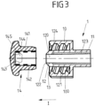
- the cap element 14 comprises a retention device 143 in the shape of a pin carrying a retention head 144 forming a circumferentially surrounding, protruding locking protrusion 145, the retention device 143 protruding from the cap head 140 into the opening formed by the insertion portion 141 along the insertion direction I.
- the retention device 143 in the shown embodiment, is rotationally symmetric, the locking protrusion 145 extending circumferentially about the retention head 144.
- the retention device 143 herein is concentrical with the insertion portion 141, the insertion portion 141 circumferentially encompassing the retention device 143.
- the retention device 143 of the cap element 14 serves to engage with a retention device 123 formed by a recess within the fluid channel 120 of the first connector 1.
- the retention device 123 in the shape of the recess is formed by a radial widening of the fluid channel 120, the recess 123 forming a stop face 124 in the vicinity of the outer end of the insertion shaft 120.
- the stop face 124 forms a step with respect to a wall 125 surrounding the fluid channel 120 in the vicinity of the outer end of the insertion shaft 12.
- the retention device 143 with its retention head 144 is plugged into the fluid channel 120 and comes into engagement with the retention device 123 formed as a recess within the fluid channel 120 such that the locking protrusion 145 abuts the stop face 124 and a positive locking engagement in between the cap element 14 and the first connector 1 is established.
- the cap element 14 hence is held on the first connector 1 such that it may not easily fall off the first connector 1.
- the cap element 14 may beneficially be formed from a soft elastic material, a user may remove the cap element 14 from the first connector 1 by pulling it off the first connector 1 in the insertion direction I.
- the retention device 123 is integrally formed with the cap element 14 and is also formed from a soft elastic material, such that the retention head 144 may deform for releasing the locking engagement with the retention device 123 in the shape of the recess formed in the fluid channel 120.
- the retention device 123 in the shape of the recess is only locally formed within the fluid channel 120.
- the retention device 123 herein is formed at the axial location at which a positive locking engagement in between the retention device 143 of the cap element 14 and the retention device 123 of the first connector 1 is to be established.
- the retention device 123 may extend all the way through the shaft 11 adjoining the body 10, as this is shown in the embodiment of Fig. 3 . This may ease the manufacturing of the first connector 1 by means of an injection molding technique because the retention device 123 in the shape of the recess may easily be formed within an injection molding tool.
- the cap element 14 may be removed from the first connector 1 such that the second connector 2 may be arranged on the first connector 1 establishing a screw connection in between the connectors 1, 2. If the second connector 2 is again removed, the cap element 14 (or another, un-used cap element 14) may be once more placed on the first connector 1.
- the invention is not limited to the embodiments described above, but may be implemented in an entirely different fashion.
- a connector assembly of the kind described herein may not only be used for the enteral feeding, but may be used for connecting any medical lines to each other for transferring medical solutions, such as medication, nutritional solutions, saline solutions or any other solutions.
Landscapes
- Health & Medical Sciences (AREA)
- Heart & Thoracic Surgery (AREA)
- Pulmonology (AREA)
- Engineering & Computer Science (AREA)
- Anesthesiology (AREA)
- Biomedical Technology (AREA)
- Hematology (AREA)
- Life Sciences & Earth Sciences (AREA)
- Animal Behavior & Ethology (AREA)
- General Health & Medical Sciences (AREA)
- Public Health (AREA)
- Veterinary Medicine (AREA)
- Infusion, Injection, And Reservoir Apparatuses (AREA)
Claims (11)
- Ensemble raccord pour raccorder des conduites médicales (3, 4) entre elles, comprenant : un premier raccord (1) ayant une tige d'insertion (12) à insérer, selon une direction d'insertion (I), dans une ouverture d'insertion (22) d'un second raccord (2) pour former un raccordement fluidique entre les conduites médicales (3, 4), la tige d'insertion (12) comprenant un canal de fluide (120) permettant au fluide de s'écouler entre le premier raccord (1) et le second raccord (2),un élément de capuchon (14) pouvant être fixé au premier raccord (1) pour fermer le canal de fluide (120) vers l'extérieur dans un état dans lequel le premier raccord (1) n'est pas raccordé au second raccord (2), le premier raccord (1) ayant un premier dispositif de retenue (123) et l'élément de capuchon (14) ayant un second dispositif de retenue (143), le premier dispositif de retenue (123) et le second dispositif de retenue (143) étant conçus pour former une mise en prise de verrouillage positif entre l'élément de capuchon (14) et le premier raccord (1) le long de la direction d'insertion (I),caractérisé en ceque le premier dispositif de retenue (123) est formé comme un évidement dans une paroi (125) entourant le canal de fluide (120).
- Ensemble raccord selon la revendication 1, caractérisé en ce que le premier dispositif de retenue (123) est formé au sein du canal de fluide (120) de la tige d'insertion (12).
- Ensemble raccord selon l'une des revendications 1 à 2, caractérisé en ce que l'élément de capuchon (14) comprend une tête de capuchon (140), le second dispositif de retenue (143) faisant saillie de la tête de capuchon (140) le long de la direction d'insertion (I).
- Ensemble raccord selon l'une des revendications précédentes, caractérisé en ce que le second dispositif de retenue (143) comprend au moins une tête de retenue (144) au niveau d'une extrémité opposée à la tête de capuchon (140), l'au moins une tête de retenue (144) étant formée pour former ladite mise en prise de verrouillage positif avec le premier dispositif de retenue (123).
- Ensemble raccord selon l'une des revendications précédentes, caractérisé en ce que la tige d'insertion (12) a une forme cylindrique ou conique, le canal de fluide (120) s'étendant le long de la direction d'insertion (I) dans la tige d'insertion (12).
- Ensemble raccord selon l'une des revendications précédentes, caractérisé en ce que le premier raccord (1) comprend un premier corps (10) s'étendant circonférentiellement autour de la tige d'insertion (12) de telle sorte qu'un espace interne (13) est formé radialement entre le premier corps (10) et la tige d'insertion (12), l'élément de capuchon (14) comprenant une partie d'insertion (141) pouvant être insérée dans l'espace interne (13).
- Ensemble raccord selon la revendication 6, caractérisé en ce que la partie d'insertion (141) est agencée de manière concentrique au second dispositif de retenue (143).
- Ensemble raccord selon la revendication 6 ou 7, caractérisé en ce que la partie d'insertion (141) est agencée radialement à l'extérieur du second dispositif de retenue (143).
- Ensemble raccord selon l'une des revendications 6 à 8, caractérisé en ce que l'élément de capuchon (14) est conçu pour fermer l'espace interne (13) vers l'extérieur lorsque l'élément de capuchon (14) est fixé au premier raccord (1).
- Ensemble raccord selon l'une des revendications 6 à 9, caractérisé en ce que le premier corps (10) comprend un filetage (100) pour raccorder le premier raccord (1) et le second raccord (2) l'un à l'autre.
- Ensemble raccord selon l'une des revendications précédentes, caractérisé en ce que le premier raccord (1) comprend une première tige de raccordement (11) alignée axialement avec la tige d'insertion (12) pour recevoir une première conduite de raccordement (3).
Applications Claiming Priority (2)
| Application Number | Priority Date | Filing Date | Title |
|---|---|---|---|
| EP18178716 | 2018-06-20 | ||
| PCT/EP2019/063935 WO2019243011A1 (fr) | 2018-06-20 | 2019-05-29 | Ensemble connecteur pour connecter des conduits médicaux comprenant un élément de capuchon |
Publications (2)
| Publication Number | Publication Date |
|---|---|
| EP3810254A1 EP3810254A1 (fr) | 2021-04-28 |
| EP3810254B1 true EP3810254B1 (fr) | 2024-02-21 |
Family
ID=62715887
Family Applications (1)
| Application Number | Title | Priority Date | Filing Date |
|---|---|---|---|
| EP19727017.6A Active EP3810254B1 (fr) | 2018-06-20 | 2019-05-29 | Ensemble raccord destiné à raccorder des tuyaux médicaux comprenant un élément de recouvrement |
Country Status (4)
| Country | Link |
|---|---|
| US (1) | US20210205597A1 (fr) |
| EP (1) | EP3810254B1 (fr) |
| CN (1) | CN112368044B (fr) |
| WO (1) | WO2019243011A1 (fr) |
Families Citing this family (1)
| Publication number | Priority date | Publication date | Assignee | Title |
|---|---|---|---|---|
| DE102022101151A1 (de) | 2022-01-19 | 2023-07-20 | B. Braun Melsungen Aktiengesellschaft | Kappe für einen Konnektor eines enteralen Überleitungssets sowie Überleitungsset mit einer Kappe |
Family Cites Families (6)
| Publication number | Priority date | Publication date | Assignee | Title |
|---|---|---|---|---|
| CN103124581A (zh) * | 2010-07-23 | 2013-05-29 | 梅德拉控股公司 | 肠内给养组件 |
| DE102011013792A1 (de) * | 2011-03-03 | 2012-09-06 | Vetter Pharma-Fertigung GmbH & Co. KG | Verschluss für eine Pulverspritze und Pulverspritze |
| EP2968868A4 (fr) * | 2013-03-14 | 2016-08-03 | Excelsior Medical Corp | Capuchon aveugle antiseptique |
| US11357964B2 (en) * | 2014-09-08 | 2022-06-14 | Avent, Inc. | Vented connector for medical fluid vessels and tapered plug |
| BR112017022203B1 (pt) * | 2015-05-22 | 2022-04-05 | Fresenius Kabi Deutschland Gmbh | Montagem de conexão para conduzir um líquido médico,elemento de vedação para uma montagem de conexão e disposição de uma montagem de conexão |
| WO2017095373A1 (fr) * | 2015-11-30 | 2017-06-08 | Avent, Inc. | Capuchon flexible pour connecteurs coniques |
-
2019
- 2019-05-29 WO PCT/EP2019/063935 patent/WO2019243011A1/fr not_active Ceased
- 2019-05-29 CN CN201980040034.4A patent/CN112368044B/zh active Active
- 2019-05-29 EP EP19727017.6A patent/EP3810254B1/fr active Active
- 2019-05-29 US US17/056,039 patent/US20210205597A1/en not_active Abandoned
Also Published As
| Publication number | Publication date |
|---|---|
| CN112368044A (zh) | 2021-02-12 |
| EP3810254A1 (fr) | 2021-04-28 |
| WO2019243011A1 (fr) | 2019-12-26 |
| CN112368044B (zh) | 2023-02-10 |
| US20210205597A1 (en) | 2021-07-08 |
Similar Documents
| Publication | Publication Date | Title |
|---|---|---|
| US11826540B2 (en) | Flexible cap for conical connectors | |
| CA3000099C (fr) | Raccord d'alimentation par voie enterale | |
| CN101534892A (zh) | 具有防止与血管内治疗系统错误连接的防护措施的肠内医疗组件 | |
| EP3565629B1 (fr) | Ensemble connecteur destiné à connecter des tuyaux médicaux les uns aux autres | |
| US20210205597A1 (en) | Connector assembly for connecting medical lines comprising a cap element | |
| EP3810255B1 (fr) | Connecteur pour relier un premier tuyau médical à un seconde tuyau médical | |
| EP3429548B1 (fr) | Raccord de dispositif d'alimentation entérale | |
| HK40044132B (en) | Connector assembly for connecting medical lines comprising a cap element | |
| HK40044132A (en) | Connector assembly for connecting medical lines comprising a cap element | |
| US10548811B2 (en) | Valve for fluid flow assembly | |
| EP3342449A1 (fr) | Dispositif comportant un orifice d'injection d'un fluide médical dans un conduit médical | |
| EP3866905A1 (fr) | Ensemble connecteur pour connecter des conduits médicaux | |
| HK40043624B (en) | Connector for connecting a first medical line to a second medical line | |
| HK40043624A (en) | Connector for connecting a first medical line to a second medical line |
Legal Events
| Date | Code | Title | Description |
|---|---|---|---|
| STAA | Information on the status of an ep patent application or granted ep patent |
Free format text: STATUS: UNKNOWN |
|
| STAA | Information on the status of an ep patent application or granted ep patent |
Free format text: STATUS: THE INTERNATIONAL PUBLICATION HAS BEEN MADE |
|
| PUAI | Public reference made under article 153(3) epc to a published international application that has entered the european phase |
Free format text: ORIGINAL CODE: 0009012 |
|
| STAA | Information on the status of an ep patent application or granted ep patent |
Free format text: STATUS: REQUEST FOR EXAMINATION WAS MADE |
|
| 17P | Request for examination filed |
Effective date: 20201022 |
|
| AK | Designated contracting states |
Kind code of ref document: A1 Designated state(s): AL AT BE BG CH CY CZ DE DK EE ES FI FR GB GR HR HU IE IS IT LI LT LU LV MC MK MT NL NO PL PT RO RS SE SI SK SM TR |
|
| AX | Request for extension of the european patent |
Extension state: BA ME |
|
| REG | Reference to a national code |
Ref country code: HK Ref legal event code: DE Ref document number: 40044132 Country of ref document: HK |
|
| DAV | Request for validation of the european patent (deleted) | ||
| DAX | Request for extension of the european patent (deleted) | ||
| GRAP | Despatch of communication of intention to grant a patent |
Free format text: ORIGINAL CODE: EPIDOSNIGR1 |
|
| STAA | Information on the status of an ep patent application or granted ep patent |
Free format text: STATUS: GRANT OF PATENT IS INTENDED |
|
| INTG | Intention to grant announced |
Effective date: 20231127 |
|
| GRAS | Grant fee paid |
Free format text: ORIGINAL CODE: EPIDOSNIGR3 |
|
| GRAA | (expected) grant |
Free format text: ORIGINAL CODE: 0009210 |
|
| STAA | Information on the status of an ep patent application or granted ep patent |
Free format text: STATUS: THE PATENT HAS BEEN GRANTED |
|
| AK | Designated contracting states |
Kind code of ref document: B1 Designated state(s): AL AT BE BG CH CY CZ DE DK EE ES FI FR GB GR HR HU IE IS IT LI LT LU LV MC MK MT NL NO PL PT RO RS SE SI SK SM TR |
|
| REG | Reference to a national code |
Ref country code: GB Ref legal event code: FG4D |
|
| REG | Reference to a national code |
Ref country code: CH Ref legal event code: EP |
|
| REG | Reference to a national code |
Ref country code: DE Ref legal event code: R096 Ref document number: 602019046901 Country of ref document: DE |
|
| REG | Reference to a national code |
Ref country code: IE Ref legal event code: FG4D |
|
| P01 | Opt-out of the competence of the unified patent court (upc) registered |
Effective date: 20240308 |
|
| REG | Reference to a national code |
Ref country code: LT Ref legal event code: MG9D |
|
| REG | Reference to a national code |
Ref country code: NL Ref legal event code: MP Effective date: 20240221 |
|
| PG25 | Lapsed in a contracting state [announced via postgrant information from national office to epo] |
Ref country code: IS Free format text: LAPSE BECAUSE OF FAILURE TO SUBMIT A TRANSLATION OF THE DESCRIPTION OR TO PAY THE FEE WITHIN THE PRESCRIBED TIME-LIMIT Effective date: 20240621 |
|
| PG25 | Lapsed in a contracting state [announced via postgrant information from national office to epo] |
Ref country code: LT Free format text: LAPSE BECAUSE OF FAILURE TO SUBMIT A TRANSLATION OF THE DESCRIPTION OR TO PAY THE FEE WITHIN THE PRESCRIBED TIME-LIMIT Effective date: 20240221 |
|
| PG25 | Lapsed in a contracting state [announced via postgrant information from national office to epo] |
Ref country code: GR Free format text: LAPSE BECAUSE OF FAILURE TO SUBMIT A TRANSLATION OF THE DESCRIPTION OR TO PAY THE FEE WITHIN THE PRESCRIBED TIME-LIMIT Effective date: 20240522 |
|
| REG | Reference to a national code |
Ref country code: AT Ref legal event code: MK05 Ref document number: 1658574 Country of ref document: AT Kind code of ref document: T Effective date: 20240221 |
|
| PG25 | Lapsed in a contracting state [announced via postgrant information from national office to epo] |
Ref country code: HR Free format text: LAPSE BECAUSE OF FAILURE TO SUBMIT A TRANSLATION OF THE DESCRIPTION OR TO PAY THE FEE WITHIN THE PRESCRIBED TIME-LIMIT Effective date: 20240221 Ref country code: NL Free format text: LAPSE BECAUSE OF FAILURE TO SUBMIT A TRANSLATION OF THE DESCRIPTION OR TO PAY THE FEE WITHIN THE PRESCRIBED TIME-LIMIT Effective date: 20240221 Ref country code: RS Free format text: LAPSE BECAUSE OF FAILURE TO SUBMIT A TRANSLATION OF THE DESCRIPTION OR TO PAY THE FEE WITHIN THE PRESCRIBED TIME-LIMIT Effective date: 20240521 |
|
| PG25 | Lapsed in a contracting state [announced via postgrant information from national office to epo] |
Ref country code: ES Free format text: LAPSE BECAUSE OF FAILURE TO SUBMIT A TRANSLATION OF THE DESCRIPTION OR TO PAY THE FEE WITHIN THE PRESCRIBED TIME-LIMIT Effective date: 20240221 |
|
| PG25 | Lapsed in a contracting state [announced via postgrant information from national office to epo] |
Ref country code: AT Free format text: LAPSE BECAUSE OF FAILURE TO SUBMIT A TRANSLATION OF THE DESCRIPTION OR TO PAY THE FEE WITHIN THE PRESCRIBED TIME-LIMIT Effective date: 20240221 |
|
| PG25 | Lapsed in a contracting state [announced via postgrant information from national office to epo] |
Ref country code: RS Free format text: LAPSE BECAUSE OF FAILURE TO SUBMIT A TRANSLATION OF THE DESCRIPTION OR TO PAY THE FEE WITHIN THE PRESCRIBED TIME-LIMIT Effective date: 20240521 Ref country code: NO Free format text: LAPSE BECAUSE OF FAILURE TO SUBMIT A TRANSLATION OF THE DESCRIPTION OR TO PAY THE FEE WITHIN THE PRESCRIBED TIME-LIMIT Effective date: 20240521 Ref country code: NL Free format text: LAPSE BECAUSE OF FAILURE TO SUBMIT A TRANSLATION OF THE DESCRIPTION OR TO PAY THE FEE WITHIN THE PRESCRIBED TIME-LIMIT Effective date: 20240221 Ref country code: LT Free format text: LAPSE BECAUSE OF FAILURE TO SUBMIT A TRANSLATION OF THE DESCRIPTION OR TO PAY THE FEE WITHIN THE PRESCRIBED TIME-LIMIT Effective date: 20240221 Ref country code: IS Free format text: LAPSE BECAUSE OF FAILURE TO SUBMIT A TRANSLATION OF THE DESCRIPTION OR TO PAY THE FEE WITHIN THE PRESCRIBED TIME-LIMIT Effective date: 20240621 Ref country code: HR Free format text: LAPSE BECAUSE OF FAILURE TO SUBMIT A TRANSLATION OF THE DESCRIPTION OR TO PAY THE FEE WITHIN THE PRESCRIBED TIME-LIMIT Effective date: 20240221 Ref country code: GR Free format text: LAPSE BECAUSE OF FAILURE TO SUBMIT A TRANSLATION OF THE DESCRIPTION OR TO PAY THE FEE WITHIN THE PRESCRIBED TIME-LIMIT Effective date: 20240522 Ref country code: FI Free format text: LAPSE BECAUSE OF FAILURE TO SUBMIT A TRANSLATION OF THE DESCRIPTION OR TO PAY THE FEE WITHIN THE PRESCRIBED TIME-LIMIT Effective date: 20240221 Ref country code: ES Free format text: LAPSE BECAUSE OF FAILURE TO SUBMIT A TRANSLATION OF THE DESCRIPTION OR TO PAY THE FEE WITHIN THE PRESCRIBED TIME-LIMIT Effective date: 20240221 Ref country code: BG Free format text: LAPSE BECAUSE OF FAILURE TO SUBMIT A TRANSLATION OF THE DESCRIPTION OR TO PAY THE FEE WITHIN THE PRESCRIBED TIME-LIMIT Effective date: 20240221 Ref country code: AT Free format text: LAPSE BECAUSE OF FAILURE TO SUBMIT A TRANSLATION OF THE DESCRIPTION OR TO PAY THE FEE WITHIN THE PRESCRIBED TIME-LIMIT Effective date: 20240221 |
|
| PG25 | Lapsed in a contracting state [announced via postgrant information from national office to epo] |
Ref country code: PT Free format text: LAPSE BECAUSE OF FAILURE TO SUBMIT A TRANSLATION OF THE DESCRIPTION OR TO PAY THE FEE WITHIN THE PRESCRIBED TIME-LIMIT Effective date: 20240621 Ref country code: PL Free format text: LAPSE BECAUSE OF FAILURE TO SUBMIT A TRANSLATION OF THE DESCRIPTION OR TO PAY THE FEE WITHIN THE PRESCRIBED TIME-LIMIT Effective date: 20240221 |
|
| PG25 | Lapsed in a contracting state [announced via postgrant information from national office to epo] |
Ref country code: SE Free format text: LAPSE BECAUSE OF FAILURE TO SUBMIT A TRANSLATION OF THE DESCRIPTION OR TO PAY THE FEE WITHIN THE PRESCRIBED TIME-LIMIT Effective date: 20240221 Ref country code: PT Free format text: LAPSE BECAUSE OF FAILURE TO SUBMIT A TRANSLATION OF THE DESCRIPTION OR TO PAY THE FEE WITHIN THE PRESCRIBED TIME-LIMIT Effective date: 20240621 Ref country code: PL Free format text: LAPSE BECAUSE OF FAILURE TO SUBMIT A TRANSLATION OF THE DESCRIPTION OR TO PAY THE FEE WITHIN THE PRESCRIBED TIME-LIMIT Effective date: 20240221 Ref country code: LV Free format text: LAPSE BECAUSE OF FAILURE TO SUBMIT A TRANSLATION OF THE DESCRIPTION OR TO PAY THE FEE WITHIN THE PRESCRIBED TIME-LIMIT Effective date: 20240221 |
|
| PG25 | Lapsed in a contracting state [announced via postgrant information from national office to epo] |
Ref country code: DK Free format text: LAPSE BECAUSE OF FAILURE TO SUBMIT A TRANSLATION OF THE DESCRIPTION OR TO PAY THE FEE WITHIN THE PRESCRIBED TIME-LIMIT Effective date: 20240221 |
|
| PG25 | Lapsed in a contracting state [announced via postgrant information from national office to epo] |
Ref country code: SM Free format text: LAPSE BECAUSE OF FAILURE TO SUBMIT A TRANSLATION OF THE DESCRIPTION OR TO PAY THE FEE WITHIN THE PRESCRIBED TIME-LIMIT Effective date: 20240221 |
|
| PG25 | Lapsed in a contracting state [announced via postgrant information from national office to epo] |
Ref country code: CZ Free format text: LAPSE BECAUSE OF FAILURE TO SUBMIT A TRANSLATION OF THE DESCRIPTION OR TO PAY THE FEE WITHIN THE PRESCRIBED TIME-LIMIT Effective date: 20240221 Ref country code: EE Free format text: LAPSE BECAUSE OF FAILURE TO SUBMIT A TRANSLATION OF THE DESCRIPTION OR TO PAY THE FEE WITHIN THE PRESCRIBED TIME-LIMIT Effective date: 20240221 |
|
| PG25 | Lapsed in a contracting state [announced via postgrant information from national office to epo] |
Ref country code: SK Free format text: LAPSE BECAUSE OF FAILURE TO SUBMIT A TRANSLATION OF THE DESCRIPTION OR TO PAY THE FEE WITHIN THE PRESCRIBED TIME-LIMIT Effective date: 20240221 |
|
| PG25 | Lapsed in a contracting state [announced via postgrant information from national office to epo] |
Ref country code: SM Free format text: LAPSE BECAUSE OF FAILURE TO SUBMIT A TRANSLATION OF THE DESCRIPTION OR TO PAY THE FEE WITHIN THE PRESCRIBED TIME-LIMIT Effective date: 20240221 Ref country code: SK Free format text: LAPSE BECAUSE OF FAILURE TO SUBMIT A TRANSLATION OF THE DESCRIPTION OR TO PAY THE FEE WITHIN THE PRESCRIBED TIME-LIMIT Effective date: 20240221 Ref country code: RO Free format text: LAPSE BECAUSE OF FAILURE TO SUBMIT A TRANSLATION OF THE DESCRIPTION OR TO PAY THE FEE WITHIN THE PRESCRIBED TIME-LIMIT Effective date: 20240221 Ref country code: EE Free format text: LAPSE BECAUSE OF FAILURE TO SUBMIT A TRANSLATION OF THE DESCRIPTION OR TO PAY THE FEE WITHIN THE PRESCRIBED TIME-LIMIT Effective date: 20240221 Ref country code: DK Free format text: LAPSE BECAUSE OF FAILURE TO SUBMIT A TRANSLATION OF THE DESCRIPTION OR TO PAY THE FEE WITHIN THE PRESCRIBED TIME-LIMIT Effective date: 20240221 Ref country code: CZ Free format text: LAPSE BECAUSE OF FAILURE TO SUBMIT A TRANSLATION OF THE DESCRIPTION OR TO PAY THE FEE WITHIN THE PRESCRIBED TIME-LIMIT Effective date: 20240221 |
|
| REG | Reference to a national code |
Ref country code: DE Ref legal event code: R097 Ref document number: 602019046901 Country of ref document: DE |
|
| PG25 | Lapsed in a contracting state [announced via postgrant information from national office to epo] |
Ref country code: IT Free format text: LAPSE BECAUSE OF FAILURE TO SUBMIT A TRANSLATION OF THE DESCRIPTION OR TO PAY THE FEE WITHIN THE PRESCRIBED TIME-LIMIT Effective date: 20240221 |
|
| PLBE | No opposition filed within time limit |
Free format text: ORIGINAL CODE: 0009261 |
|
| STAA | Information on the status of an ep patent application or granted ep patent |
Free format text: STATUS: NO OPPOSITION FILED WITHIN TIME LIMIT |
|
| REG | Reference to a national code |
Ref country code: CH Ref legal event code: PL |
|
| PG25 | Lapsed in a contracting state [announced via postgrant information from national office to epo] |
Ref country code: IT Free format text: LAPSE BECAUSE OF FAILURE TO SUBMIT A TRANSLATION OF THE DESCRIPTION OR TO PAY THE FEE WITHIN THE PRESCRIBED TIME-LIMIT Effective date: 20240221 |
|
| PG25 | Lapsed in a contracting state [announced via postgrant information from national office to epo] |
Ref country code: MC Free format text: LAPSE BECAUSE OF FAILURE TO SUBMIT A TRANSLATION OF THE DESCRIPTION OR TO PAY THE FEE WITHIN THE PRESCRIBED TIME-LIMIT Effective date: 20240221 |
|
| PG25 | Lapsed in a contracting state [announced via postgrant information from national office to epo] |
Ref country code: LU Free format text: LAPSE BECAUSE OF NON-PAYMENT OF DUE FEES Effective date: 20240529 |
|
| 26N | No opposition filed |
Effective date: 20241122 |
|
| PG25 | Lapsed in a contracting state [announced via postgrant information from national office to epo] |
Ref country code: MC Free format text: LAPSE BECAUSE OF FAILURE TO SUBMIT A TRANSLATION OF THE DESCRIPTION OR TO PAY THE FEE WITHIN THE PRESCRIBED TIME-LIMIT Effective date: 20240221 Ref country code: LU Free format text: LAPSE BECAUSE OF NON-PAYMENT OF DUE FEES Effective date: 20240529 Ref country code: CH Free format text: LAPSE BECAUSE OF NON-PAYMENT OF DUE FEES Effective date: 20240531 |
|
| REG | Reference to a national code |
Ref country code: BE Ref legal event code: MM Effective date: 20240531 |
|
| PG25 | Lapsed in a contracting state [announced via postgrant information from national office to epo] |
Ref country code: IE Free format text: LAPSE BECAUSE OF NON-PAYMENT OF DUE FEES Effective date: 20240529 |
|
| PG25 | Lapsed in a contracting state [announced via postgrant information from national office to epo] |
Ref country code: SI Free format text: LAPSE BECAUSE OF FAILURE TO SUBMIT A TRANSLATION OF THE DESCRIPTION OR TO PAY THE FEE WITHIN THE PRESCRIBED TIME-LIMIT Effective date: 20240221 Ref country code: BE Free format text: LAPSE BECAUSE OF NON-PAYMENT OF DUE FEES Effective date: 20240531 |
|
| PGFP | Annual fee paid to national office [announced via postgrant information from national office to epo] |
Ref country code: DE Payment date: 20250529 Year of fee payment: 7 |
|
| PGFP | Annual fee paid to national office [announced via postgrant information from national office to epo] |
Ref country code: GB Payment date: 20250527 Year of fee payment: 7 |
|
| PGFP | Annual fee paid to national office [announced via postgrant information from national office to epo] |
Ref country code: FR Payment date: 20250526 Year of fee payment: 7 |
|
| PG25 | Lapsed in a contracting state [announced via postgrant information from national office to epo] |
Ref country code: CY Free format text: LAPSE BECAUSE OF FAILURE TO SUBMIT A TRANSLATION OF THE DESCRIPTION OR TO PAY THE FEE WITHIN THE PRESCRIBED TIME-LIMIT; INVALID AB INITIO Effective date: 20190529 |
|
| PG25 | Lapsed in a contracting state [announced via postgrant information from national office to epo] |
Ref country code: HU Free format text: LAPSE BECAUSE OF FAILURE TO SUBMIT A TRANSLATION OF THE DESCRIPTION OR TO PAY THE FEE WITHIN THE PRESCRIBED TIME-LIMIT; INVALID AB INITIO Effective date: 20190529 |