EP3810314B1 - Pompe centrifuge - Google Patents
Pompe centrifuge Download PDFInfo
- Publication number
- EP3810314B1 EP3810314B1 EP19803929.9A EP19803929A EP3810314B1 EP 3810314 B1 EP3810314 B1 EP 3810314B1 EP 19803929 A EP19803929 A EP 19803929A EP 3810314 B1 EP3810314 B1 EP 3810314B1
- Authority
- EP
- European Patent Office
- Prior art keywords
- propeller
- pump
- casing
- pump casing
- fluid
- Prior art date
- Legal status (The legal status is an assumption and is not a legal conclusion. Google has not performed a legal analysis and makes no representation as to the accuracy of the status listed.)
- Active
Links
Images
Classifications
-
- F—MECHANICAL ENGINEERING; LIGHTING; HEATING; WEAPONS; BLASTING
- F04—POSITIVE - DISPLACEMENT MACHINES FOR LIQUIDS; PUMPS FOR LIQUIDS OR ELASTIC FLUIDS
- F04D—NON-POSITIVE-DISPLACEMENT PUMPS
- F04D29/00—Details, component parts, or accessories
- F04D29/40—Casings; Connections of working fluid
- F04D29/42—Casings; Connections of working fluid for radial or helico-centrifugal pumps
- F04D29/426—Casings; Connections of working fluid for radial or helico-centrifugal pumps especially adapted for liquid pumps
-
- F—MECHANICAL ENGINEERING; LIGHTING; HEATING; WEAPONS; BLASTING
- F04—POSITIVE - DISPLACEMENT MACHINES FOR LIQUIDS; PUMPS FOR LIQUIDS OR ELASTIC FLUIDS
- F04D—NON-POSITIVE-DISPLACEMENT PUMPS
- F04D1/00—Radial-flow pumps, e.g. centrifugal pumps; Helico-centrifugal pumps
-
- F—MECHANICAL ENGINEERING; LIGHTING; HEATING; WEAPONS; BLASTING
- F04—POSITIVE - DISPLACEMENT MACHINES FOR LIQUIDS; PUMPS FOR LIQUIDS OR ELASTIC FLUIDS
- F04D—NON-POSITIVE-DISPLACEMENT PUMPS
- F04D1/00—Radial-flow pumps, e.g. centrifugal pumps; Helico-centrifugal pumps
- F04D1/04—Helico-centrifugal pumps
-
- F—MECHANICAL ENGINEERING; LIGHTING; HEATING; WEAPONS; BLASTING
- F04—POSITIVE - DISPLACEMENT MACHINES FOR LIQUIDS; PUMPS FOR LIQUIDS OR ELASTIC FLUIDS
- F04D—NON-POSITIVE-DISPLACEMENT PUMPS
- F04D1/00—Radial-flow pumps, e.g. centrifugal pumps; Helico-centrifugal pumps
- F04D1/14—Pumps raising fluids by centrifugal force within a conical rotary bowl with vertical axis
-
- F—MECHANICAL ENGINEERING; LIGHTING; HEATING; WEAPONS; BLASTING
- F04—POSITIVE - DISPLACEMENT MACHINES FOR LIQUIDS; PUMPS FOR LIQUIDS OR ELASTIC FLUIDS
- F04D—NON-POSITIVE-DISPLACEMENT PUMPS
- F04D29/00—Details, component parts, or accessories
- F04D29/18—Rotors
- F04D29/181—Axial flow rotors
-
- F—MECHANICAL ENGINEERING; LIGHTING; HEATING; WEAPONS; BLASTING
- F04—POSITIVE - DISPLACEMENT MACHINES FOR LIQUIDS; PUMPS FOR LIQUIDS OR ELASTIC FLUIDS
- F04D—NON-POSITIVE-DISPLACEMENT PUMPS
- F04D29/00—Details, component parts, or accessories
- F04D29/18—Rotors
- F04D29/22—Rotors specially for centrifugal pumps
-
- F—MECHANICAL ENGINEERING; LIGHTING; HEATING; WEAPONS; BLASTING
- F04—POSITIVE - DISPLACEMENT MACHINES FOR LIQUIDS; PUMPS FOR LIQUIDS OR ELASTIC FLUIDS
- F04D—NON-POSITIVE-DISPLACEMENT PUMPS
- F04D29/00—Details, component parts, or accessories
- F04D29/26—Rotors specially for elastic fluids
- F04D29/28—Rotors specially for elastic fluids for centrifugal or helico-centrifugal pumps for radial-flow or helico-centrifugal pumps
-
- F—MECHANICAL ENGINEERING; LIGHTING; HEATING; WEAPONS; BLASTING
- F04—POSITIVE - DISPLACEMENT MACHINES FOR LIQUIDS; PUMPS FOR LIQUIDS OR ELASTIC FLUIDS
- F04D—NON-POSITIVE-DISPLACEMENT PUMPS
- F04D29/00—Details, component parts, or accessories
- F04D29/40—Casings; Connections of working fluid
- F04D29/42—Casings; Connections of working fluid for radial or helico-centrifugal pumps
-
- F—MECHANICAL ENGINEERING; LIGHTING; HEATING; WEAPONS; BLASTING
- F04—POSITIVE - DISPLACEMENT MACHINES FOR LIQUIDS; PUMPS FOR LIQUIDS OR ELASTIC FLUIDS
- F04D—NON-POSITIVE-DISPLACEMENT PUMPS
- F04D29/00—Details, component parts, or accessories
- F04D29/60—Mounting; Assembling; Disassembling
- F04D29/62—Mounting; Assembling; Disassembling of radial or helico-centrifugal pumps
-
- F—MECHANICAL ENGINEERING; LIGHTING; HEATING; WEAPONS; BLASTING
- F04—POSITIVE - DISPLACEMENT MACHINES FOR LIQUIDS; PUMPS FOR LIQUIDS OR ELASTIC FLUIDS
- F04D—NON-POSITIVE-DISPLACEMENT PUMPS
- F04D7/00—Pumps adapted for handling specific fluids, e.g. by selection of specific materials for pumps or pump parts
- F04D7/02—Pumps adapted for handling specific fluids, e.g. by selection of specific materials for pumps or pump parts of centrifugal type
- F04D7/04—Pumps adapted for handling specific fluids, e.g. by selection of specific materials for pumps or pump parts of centrifugal type the fluids being viscous or non-homogenous
-
- F—MECHANICAL ENGINEERING; LIGHTING; HEATING; WEAPONS; BLASTING
- F05—INDEXING SCHEMES RELATING TO ENGINES OR PUMPS IN VARIOUS SUBCLASSES OF CLASSES F01-F04
- F05D—INDEXING SCHEME FOR ASPECTS RELATING TO NON-POSITIVE-DISPLACEMENT MACHINES OR ENGINES, GAS-TURBINES OR JET-PROPULSION PLANTS
- F05D2260/00—Function
- F05D2260/60—Fluid transfer
- F05D2260/604—Vortex non-clogging type pumps
Definitions
- the invention relates to improvements related to centrifugal pumps and, more specifically, to a centrifugal pump and a related method.
- centrifugal pumps are simple and reliable machines consisting of: 1) a fixed pump casing with an inlet and an outlet and a bearing housing placed centrally; 2) an impeller supported in the bearing housing and brought to rotate by a motor.
- the pumping medium is carried axially into the impeller and by way of the latter kinetic energy is imparted in the form of tangential and radial velocity. Part of the velocity is retarded in the spacious peripheral part of the casing; thereby there is a pressure rise in the medium.
- a known problem with the prior art is that the impeller easily becomes clogged or damaged if the pumping medium contains larger solid or tough elements. If the solid elements are fragile, these are also easily damaged when passing the impeller.
- the problem has previously sought to be solved by withdrawing the impeller, with open blades, out of the fluid stream, so that it creates a rotating vortex in the pump casing that transmits the rotation to the fluid stream by viscous forces, which results in poor efficiency.
- a known problem with the prior art is also that large-capacity centrifugal pumps become very costly to buy and operate: A low number of revolutions and high output require a strong shaft/bearing/seal system; a powerful gear box is often necessary for optimal operation. Casting and accurate machining of large metal parts such as the impeller, pump casing and shaft are expensive; maintenance/service is expensive as well.
- Document DE20 2006 005 067 U1 describes a detachable pump.
- the pump has a main pump and a loading pump that are formed as separate units, where the main pump is designed as tandem pump.
- Document DE 572 787 C describes an underwater propeller pump, in which the water is supplied to the propeller in a whirling direction opposite to the direction of rotation of the propeller.
- Patent US 6,533,622 B1 describes an axial pump with a propeller located within a cylindrical inlet. An outlet is arranged as an increasing spiral channel immediately downstream of the propeller.
- the invention has for its object to remedy or to reduce at least one of the drawbacks of the prior art or at least provide a useful alternative to the prior art.
- the invention provides a centrifugal pump according to claim 1.
- a centrifugal pump does not have a conventional, centrally placed impeller.
- the pump comprises a centrifugal pump casing having an inlet for fluid at the centre of the pump casing and an outlet at the periphery of the pump casing, wherein rotation of the fluid around the centre of the pump casing and thereby pressure increase and capacity of the fluid is obtained by one or more active propellers placed inside the pump casing at a distance from the centre of the pump casing and the propeller shaft is approximately tangential to the rotating fluid.
- the propeller may have an adapted grating on the propeller's inlet side, and the propeller with the grating on the inlet side may act directly on a limited part of the fluid, so that harmful or fragile elements in the fluid may pass the pump unobstructedly and without contact with the propeller.
- the propeller, or propellers may be placed at an optimal distance from the pump centre, regardless of the pump-casing diameter.
- the propeller(s) may be placed in a pocket (pockets) or a pipe (pipes) in the casing side or casing periphery or where a propeller nozzle surrounds the propeller.
- the centrifugal pump may further have a bearing, a bushing, a seal, a mounting flange and a motor coupling which with the propeller, the shaft and the motor are fitted together as a unit which can easily be released from the pump casing by releasing the mounting flange, so that servicing and inspection of these parts is simplified.
- the centrifugal pump may have a fast-rotating propeller with an optimized pitch direct-coupled to a fast-rotating drive unit, so that it is possible to have a hydrodynamic step-down gearing system.
- the pump casing may be submerged in the fluid, while the motor is placed above the liquid surface on an extended propeller shaft.
- the propeller may have twistable blades, possibly twistable guide blades, so that the propeller pitch can be adjusted for different or varying operating conditions.
- the invention provides a method according to claim 9, namely a method for pumping a medium by using a centrifugal pump according to the first aspect of the invention.
- the method may comprise activating the propeller into rotating about an axis so that the fluid from the pump inlet is set into rotation in the pump casing and is driven out of the outlet from the pump.
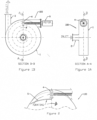
- a centrifugal pump 100 according to the invention as shown in Figures 1A and 1B has a generally conventional centrifugal pump casing 1, with an inlet 2 for the fluid at the centre and an outlet 3 at the periphery. An impeller/shaft system at the centre is eliminated.
- One (or more) motor-driven propeller(s) 4 is (are) placed in the fluid tangentially to the casing 1. When the propeller is activated in the fluid, the latter is set into rotation in the casing 1, both directly by the propeller jet and by viscous forces in the rest of the casing volume. The centrifugal force and a certain retardation of the fluid at the outlet produces pressure increase and capacity.
- the propeller 4 has a pitch which is adapted to the pump characteristics and the number of revolutions of the motor; a smaller fast-running motor with no step-down gearing may be used.
- the shaft/bearing/seal system too, is reduced in size and simplified.
- the pump casing 1 is simplified and requires little machining.
- a grating 5 as shown in Figure 2 may be placed on the inlet side of the propeller 4 and formed in such a way that larger solid, tough or fragile elements avoid contact with the latter.
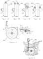
- FIGs 3A to 3D Alternative placements of the tangential propeller 4 are shown in Figures 3A to 3D .
- the propeller 4 with a shaft 11, a bearing, a bushing 10, a seal 12, a mounting flange 8 and a motor with a motor coupling 13 may easily be built as a unit 6 which can be easily taken out of the pump casing 1 for service/cleaning/inspection by releasing the mounting flange 8.
- the propeller 4 may have a settable or continuously adjustably pitch, or adjustable guide blades 14.
- the pump 100 is not self-suctioning; when placed above the liquid surface, a suction line must normally have a check valve.
- a watertight motor When placed below the liquid surface, a watertight motor may be used, or the motor 9 may be mounted above the liquid surface with an extended shaft 15, as shown in Figure 5 .
Landscapes
- Engineering & Computer Science (AREA)
- Mechanical Engineering (AREA)
- General Engineering & Computer Science (AREA)
- Structures Of Non-Positive Displacement Pumps (AREA)
Claims (11)
- Pompe centrifuge sans roue placée au centre, la pompe centrifuge comprenant un boîtier (1) de pompe, une ou plusieurs hélices (4) actives et un arbre d'hélice (11) et un moteur (9) correspondants,le boîtier (1) de pompe étant un boîtier (1) de pompe centrifuge présentant une entrée (2) pour le fluide au centre du boîtier (1) de pompe et une sortie (3) à la périphérie du boîtier (1) de pompe, caractérisée en ce queune rotation du fluide autour du centre du boîtier (1) de pompe et ainsi une augmentation de pression et une capacité du fluide sont obtenues par les une ou plusieurs hélices (4) actives placées à l'intérieur du boîtier (1) de pompe à une distance du centre du boîtier (1) de pompe et l'arbre d'hélice (11) est approximativement tangentiel au fluide en rotation.
- Pompe centrifuge selon la revendication 1, dans laquelle une grille (5) adaptée sur le côté d'entrée de l'hélice est configurée pour agir directement sur une partie limitée du fluide, de sorte que des éléments nocifs ou fragiles dans le fluide puissent passer la pompe sans obstruction et sans contact avec l'hélice (4).
- Pompe centrifuge selon la revendication 1 ou la revendication 2, dans laquelle la distance est une distance optimale à partir du centre du boîtier (1) de pompe, quel que soit le diamètre du boîtier de pompe.
- Pompe centrifuge selon l'une quelconque des revendications précédentes, dans laquelle l'hélice (4) est placée dans une poche ou un tuyau dans le côté du boîtier ou la périphérie du boîtier ou dans laquelle une buse d'hélice entoure l'hélice.
- Pompe centrifuge selon l'une quelconque des revendications précédentes, dans laquelle l'hélice (4) avec l'arbre d'hélice (11), un roulement, une bague, un joint, une bride de montage et le moteur (9) avec un accouplement de moteur sont assemblés ensemble en une unité qui peut facilement être libérée du boîtier de pompe en libérant la bride de montage, de sorte que l'entretien et l'inspection de ces pièces soient simplifiés.
- Pompe centrifuge selon l'une quelconque des revendications précédentes, dans laquelle le moteur (9) est une unité d'entraînement à rotation rapide accouplée directement à l'hélice et dans laquelle l'hélice (4) présente un pas optimisé correspondant, de sorte qu'un système d'engrenage réducteur hydrodynamique soit fourni.
- Pompe centrifuge selon l'une quelconque des revendications précédentes, dans laquelle le boîtier (1) de pompe est configuré pour être immergé dans le fluide, dans laquelle l'arbre d'hélice (11) est un arbre d'hélice étendu (15), et dans lequel le moteur (9) est configuré pour être placé au-dessus de la surface liquide sur l'arbre d'hélice étendu (15).
- Pompe centrifuge selon l'une quelconque des revendications précédentes, dans laquelle l'hélice présente des pales déformables, éventuellement des pales de guidage déformables, de sorte que le pas de l'hélice puisse être adapté à des conditions de fonctionnement différentes ou variables.
- Procédé de pompage d'un milieu à l'aide d'une pompe centrifuge selon l'une quelconque des revendications précédentes.
- Procédé selon la revendication 9, comprenant en outre l'activation de l'hélice (4) pour tourner autour de l'arbre d'hélice (11), de sorte que le fluide provenant de l'entrée (2) de pompe soit mis en rotation dans le boîtier (1) de pompe et entraîné hors de la sortie (3) de la pompe.
- Procédé selon la revendication 9 ou la revendication 10, dans lequel le boîtier (1) de pompe est situé sous la surface de l'eau.
Applications Claiming Priority (2)
| Application Number | Priority Date | Filing Date | Title |
|---|---|---|---|
| NO20180691A NO344723B1 (no) | 2018-05-16 | 2018-05-16 | Sentrifugalpumpe |
| PCT/NO2019/050109 WO2019221610A1 (fr) | 2018-05-16 | 2019-05-16 | Pompe centrifuge |
Publications (4)
| Publication Number | Publication Date |
|---|---|
| EP3810314A1 EP3810314A1 (fr) | 2021-04-28 |
| EP3810314A4 EP3810314A4 (fr) | 2022-01-19 |
| EP3810314B1 true EP3810314B1 (fr) | 2024-06-26 |
| EP3810314C0 EP3810314C0 (fr) | 2024-06-26 |
Family
ID=68540653
Family Applications (1)
| Application Number | Title | Priority Date | Filing Date |
|---|---|---|---|
| EP19803929.9A Active EP3810314B1 (fr) | 2018-05-16 | 2019-05-16 | Pompe centrifuge |
Country Status (3)
| Country | Link |
|---|---|
| EP (1) | EP3810314B1 (fr) |
| NO (1) | NO344723B1 (fr) |
| WO (1) | WO2019221610A1 (fr) |
Family Cites Families (10)
| Publication number | Priority date | Publication date | Assignee | Title |
|---|---|---|---|---|
| GB190313384A (en) * | 1903-06-15 | 1903-07-30 | Louis Ross Alberger | An Improved Steam Condenser System. |
| US1720333A (en) * | 1928-08-25 | 1929-07-09 | James T Ketchum | Circulator for hot-water systems |
| DE572787C (de) * | 1932-03-17 | 1933-03-23 | Koester Friedrich | Unterwasserpropellerpumpe |
| US2791406A (en) * | 1955-06-28 | 1957-05-07 | Chemineer | Fluid agitating devices |
| US3904714A (en) * | 1973-09-26 | 1975-09-09 | Rexnord Inc | Low-speed mechanical aerator impeller |
| BE884216A (nl) * | 1980-07-08 | 1980-11-03 | Haegeman Johny H | Inrichting voor het mengen van gas met vloeistof of omgekeerd en voor het ontgassen van een vloeistof |
| AUPP804799A0 (en) * | 1999-01-07 | 1999-01-28 | Zwaan, Craig | Jet propulsion pump |
| US6964511B2 (en) * | 2002-02-21 | 2005-11-15 | The Maitland Company | Mixing apparatus and method |
| SE525412C2 (sv) * | 2003-10-20 | 2005-02-15 | Itt Mfg Enterprises Inc | Centrifugalpump |
| DE202006005067U1 (de) * | 2006-03-29 | 2007-08-09 | Liebherr-Machines Bulle S.A. | Hydraulikpumpe |
-
2018
- 2018-05-16 NO NO20180691A patent/NO344723B1/no unknown
-
2019
- 2019-05-16 EP EP19803929.9A patent/EP3810314B1/fr active Active
- 2019-05-16 WO PCT/NO2019/050109 patent/WO2019221610A1/fr not_active Ceased
Also Published As
| Publication number | Publication date |
|---|---|
| NO344723B1 (no) | 2020-03-23 |
| EP3810314A1 (fr) | 2021-04-28 |
| NO20180691A1 (no) | 2019-11-18 |
| EP3810314A4 (fr) | 2022-01-19 |
| EP3810314C0 (fr) | 2024-06-26 |
| WO2019221610A1 (fr) | 2019-11-21 |
Similar Documents
| Publication | Publication Date | Title |
|---|---|---|
| AU2012267258B2 (en) | Multistage comminuting pump | |
| EP0837989B1 (fr) | Rotor | |
| EP2302201B1 (fr) | Système de pompe ayant appareil pour récupérer de l'énergie | |
| US3786996A (en) | Axial flow unit | |
| EP3276178B1 (fr) | Pompe à volute | |
| SE467466B (sv) | Apparat foer fluidisering, gasavskiljning och pumpning av en suspension av fiberhaltigt cellulosamaterial, samt dess anvaendning | |
| EA007556B1 (ru) | Центробежный насос | |
| KR101695444B1 (ko) | 펌프 | |
| US5102297A (en) | Centrifugal pump with cavitation reducing propeller | |
| CS203075B2 (en) | Pump,especially of submersible type | |
| US5332355A (en) | Impelling apparatus | |
| CA2515496C (fr) | Pompe ou turbine, unite d'entrainement les comportant, et moteur de hors-bord | |
| AU694679B2 (en) | A rotor | |
| EP3810314A1 (fr) | Pompe centrifuge | |
| CN110081017B (zh) | 一种潜水排污泵的叶轮 | |
| GB2054748A (en) | Pump impeller | |
| EP3828419B1 (fr) | Pompe centrifuge à étages multiples | |
| CN114962337A (zh) | 一种用于立式离心泵的下沉式进口导叶 | |
| RU2182263C2 (ru) | Центробежный насос | |
| JPH05321867A (ja) | 混流羽根と遠心羽根を一体化した複合インペラー | |
| RU2075653C1 (ru) | Оседиагональный шнековый консольный насос | |
| KR102774398B1 (ko) | 텅베인이 적용된 고효율 원심펌프 | |
| WO2020005185A2 (fr) | Rotor de pompe centrifuge | |
| RU2005217C1 (ru) | Многоступенчатый осевой насос дл перекачки неоднородных сред | |
| GB2083136A (en) | Slurry pump |
Legal Events
| Date | Code | Title | Description |
|---|---|---|---|
| STAA | Information on the status of an ep patent application or granted ep patent |
Free format text: STATUS: THE INTERNATIONAL PUBLICATION HAS BEEN MADE |
|
| PUAI | Public reference made under article 153(3) epc to a published international application that has entered the european phase |
Free format text: ORIGINAL CODE: 0009012 |
|
| STAA | Information on the status of an ep patent application or granted ep patent |
Free format text: STATUS: REQUEST FOR EXAMINATION WAS MADE |
|
| 17P | Request for examination filed |
Effective date: 20201209 |
|
| AK | Designated contracting states |
Kind code of ref document: A1 Designated state(s): AL AT BE BG CH CY CZ DE DK EE ES FI FR GB GR HR HU IE IS IT LI LT LU LV MC MK MT NL NO PL PT RO RS SE SI SK SM TR |
|
| AX | Request for extension of the european patent |
Extension state: BA ME |
|
| DAV | Request for validation of the european patent (deleted) | ||
| DAX | Request for extension of the european patent (deleted) | ||
| REG | Reference to a national code |
Ref country code: DE Ref legal event code: R079 Free format text: PREVIOUS MAIN CLASS: B01F0007220000 Ipc: F04D0001000000 Ref country code: DE Ref legal event code: R079 Ref document number: 602019054297 Country of ref document: DE Free format text: PREVIOUS MAIN CLASS: B01F0007220000 Ipc: F04D0001000000 |
|
| A4 | Supplementary search report drawn up and despatched |
Effective date: 20211220 |
|
| RIC1 | Information provided on ipc code assigned before grant |
Ipc: F04D 29/42 20060101ALI20211214BHEP Ipc: F04D 29/18 20060101ALI20211214BHEP Ipc: F04D 7/04 20060101ALI20211214BHEP Ipc: F04D 1/00 20060101AFI20211214BHEP |
|
| GRAP | Despatch of communication of intention to grant a patent |
Free format text: ORIGINAL CODE: EPIDOSNIGR1 |
|
| STAA | Information on the status of an ep patent application or granted ep patent |
Free format text: STATUS: GRANT OF PATENT IS INTENDED |
|
| INTG | Intention to grant announced |
Effective date: 20231208 |
|
| GRAS | Grant fee paid |
Free format text: ORIGINAL CODE: EPIDOSNIGR3 |
|
| GRAA | (expected) grant |
Free format text: ORIGINAL CODE: 0009210 |
|
| STAA | Information on the status of an ep patent application or granted ep patent |
Free format text: STATUS: THE PATENT HAS BEEN GRANTED |
|
| AK | Designated contracting states |
Kind code of ref document: B1 Designated state(s): AL AT BE BG CH CY CZ DE DK EE ES FI FR GB GR HR HU IE IS IT LI LT LU LV MC MK MT NL NO PL PT RO RS SE SI SK SM TR |
|
| REG | Reference to a national code |
Ref country code: GB Ref legal event code: FG4D |
|
| REG | Reference to a national code |
Ref country code: CH Ref legal event code: EP |
|
| REG | Reference to a national code |
Ref country code: DE Ref legal event code: R096 Ref document number: 602019054297 Country of ref document: DE |
|
| U01 | Request for unitary effect filed |
Effective date: 20240724 |
|
| U07 | Unitary effect registered |
Designated state(s): AT BE BG DE DK EE FI FR IT LT LU LV MT NL PT SE SI Effective date: 20240805 |
|
| PG25 | Lapsed in a contracting state [announced via postgrant information from national office to epo] |
Ref country code: HR Free format text: LAPSE BECAUSE OF FAILURE TO SUBMIT A TRANSLATION OF THE DESCRIPTION OR TO PAY THE FEE WITHIN THE PRESCRIBED TIME-LIMIT Effective date: 20240626 |
|
| PG25 | Lapsed in a contracting state [announced via postgrant information from national office to epo] |
Ref country code: GR Free format text: LAPSE BECAUSE OF FAILURE TO SUBMIT A TRANSLATION OF THE DESCRIPTION OR TO PAY THE FEE WITHIN THE PRESCRIBED TIME-LIMIT Effective date: 20240927 |
|
| PG25 | Lapsed in a contracting state [announced via postgrant information from national office to epo] |
Ref country code: NO Free format text: LAPSE BECAUSE OF FAILURE TO SUBMIT A TRANSLATION OF THE DESCRIPTION OR TO PAY THE FEE WITHIN THE PRESCRIBED TIME-LIMIT Effective date: 20240926 Ref country code: HR Free format text: LAPSE BECAUSE OF FAILURE TO SUBMIT A TRANSLATION OF THE DESCRIPTION OR TO PAY THE FEE WITHIN THE PRESCRIBED TIME-LIMIT Effective date: 20240626 Ref country code: GR Free format text: LAPSE BECAUSE OF FAILURE TO SUBMIT A TRANSLATION OF THE DESCRIPTION OR TO PAY THE FEE WITHIN THE PRESCRIBED TIME-LIMIT Effective date: 20240927 Ref country code: RS Free format text: LAPSE BECAUSE OF FAILURE TO SUBMIT A TRANSLATION OF THE DESCRIPTION OR TO PAY THE FEE WITHIN THE PRESCRIBED TIME-LIMIT Effective date: 20240926 |
|
| PG25 | Lapsed in a contracting state [announced via postgrant information from national office to epo] |
Ref country code: PL Free format text: LAPSE BECAUSE OF FAILURE TO SUBMIT A TRANSLATION OF THE DESCRIPTION OR TO PAY THE FEE WITHIN THE PRESCRIBED TIME-LIMIT Effective date: 20240626 |
|
| PG25 | Lapsed in a contracting state [announced via postgrant information from national office to epo] |
Ref country code: IS Free format text: LAPSE BECAUSE OF FAILURE TO SUBMIT A TRANSLATION OF THE DESCRIPTION OR TO PAY THE FEE WITHIN THE PRESCRIBED TIME-LIMIT Effective date: 20241026 |
|
| PG25 | Lapsed in a contracting state [announced via postgrant information from national office to epo] |
Ref country code: CZ Free format text: LAPSE BECAUSE OF FAILURE TO SUBMIT A TRANSLATION OF THE DESCRIPTION OR TO PAY THE FEE WITHIN THE PRESCRIBED TIME-LIMIT Effective date: 20240626 |
|
| PG25 | Lapsed in a contracting state [announced via postgrant information from national office to epo] |
Ref country code: SK Free format text: LAPSE BECAUSE OF FAILURE TO SUBMIT A TRANSLATION OF THE DESCRIPTION OR TO PAY THE FEE WITHIN THE PRESCRIBED TIME-LIMIT Effective date: 20240626 Ref country code: RO Free format text: LAPSE BECAUSE OF FAILURE TO SUBMIT A TRANSLATION OF THE DESCRIPTION OR TO PAY THE FEE WITHIN THE PRESCRIBED TIME-LIMIT Effective date: 20240626 |
|
| PG25 | Lapsed in a contracting state [announced via postgrant information from national office to epo] |
Ref country code: SM Free format text: LAPSE BECAUSE OF FAILURE TO SUBMIT A TRANSLATION OF THE DESCRIPTION OR TO PAY THE FEE WITHIN THE PRESCRIBED TIME-LIMIT Effective date: 20240626 Ref country code: ES Free format text: LAPSE BECAUSE OF FAILURE TO SUBMIT A TRANSLATION OF THE DESCRIPTION OR TO PAY THE FEE WITHIN THE PRESCRIBED TIME-LIMIT Effective date: 20240626 |
|
| PG25 | Lapsed in a contracting state [announced via postgrant information from national office to epo] |
Ref country code: SM Free format text: LAPSE BECAUSE OF FAILURE TO SUBMIT A TRANSLATION OF THE DESCRIPTION OR TO PAY THE FEE WITHIN THE PRESCRIBED TIME-LIMIT Effective date: 20240626 Ref country code: SK Free format text: LAPSE BECAUSE OF FAILURE TO SUBMIT A TRANSLATION OF THE DESCRIPTION OR TO PAY THE FEE WITHIN THE PRESCRIBED TIME-LIMIT Effective date: 20240626 Ref country code: RO Free format text: LAPSE BECAUSE OF FAILURE TO SUBMIT A TRANSLATION OF THE DESCRIPTION OR TO PAY THE FEE WITHIN THE PRESCRIBED TIME-LIMIT Effective date: 20240626 Ref country code: PL Free format text: LAPSE BECAUSE OF FAILURE TO SUBMIT A TRANSLATION OF THE DESCRIPTION OR TO PAY THE FEE WITHIN THE PRESCRIBED TIME-LIMIT Effective date: 20240626 Ref country code: IS Free format text: LAPSE BECAUSE OF FAILURE TO SUBMIT A TRANSLATION OF THE DESCRIPTION OR TO PAY THE FEE WITHIN THE PRESCRIBED TIME-LIMIT Effective date: 20241026 Ref country code: ES Free format text: LAPSE BECAUSE OF FAILURE TO SUBMIT A TRANSLATION OF THE DESCRIPTION OR TO PAY THE FEE WITHIN THE PRESCRIBED TIME-LIMIT Effective date: 20240626 Ref country code: CZ Free format text: LAPSE BECAUSE OF FAILURE TO SUBMIT A TRANSLATION OF THE DESCRIPTION OR TO PAY THE FEE WITHIN THE PRESCRIBED TIME-LIMIT Effective date: 20240626 |
|
| PLBE | No opposition filed within time limit |
Free format text: ORIGINAL CODE: 0009261 |
|
| STAA | Information on the status of an ep patent application or granted ep patent |
Free format text: STATUS: NO OPPOSITION FILED WITHIN TIME LIMIT |
|
| 26N | No opposition filed |
Effective date: 20250327 |
|
| U20 | Renewal fee for the european patent with unitary effect paid |
Year of fee payment: 7 Effective date: 20250512 |
|
| REG | Reference to a national code |
Ref country code: CH Ref legal event code: H13 Free format text: ST27 STATUS EVENT CODE: U-0-0-H10-H13 (AS PROVIDED BY THE NATIONAL OFFICE) Effective date: 20251223 |
|
| PG25 | Lapsed in a contracting state [announced via postgrant information from national office to epo] |
Ref country code: CH Free format text: LAPSE BECAUSE OF NON-PAYMENT OF DUE FEES Effective date: 20250531 |
|
| GBPC | Gb: european patent ceased through non-payment of renewal fee |
Effective date: 20250516 |
|
| PG25 | Lapsed in a contracting state [announced via postgrant information from national office to epo] |
Ref country code: MC Free format text: LAPSE BECAUSE OF FAILURE TO SUBMIT A TRANSLATION OF THE DESCRIPTION OR TO PAY THE FEE WITHIN THE PRESCRIBED TIME-LIMIT Effective date: 20240626 |
|
| PG25 | Lapsed in a contracting state [announced via postgrant information from national office to epo] |
Ref country code: GB Free format text: LAPSE BECAUSE OF NON-PAYMENT OF DUE FEES Effective date: 20250516 |
|
| PG25 | Lapsed in a contracting state [announced via postgrant information from national office to epo] |
Ref country code: IE Free format text: LAPSE BECAUSE OF NON-PAYMENT OF DUE FEES Effective date: 20250516 |
|
| U20 | Renewal fee for the european patent with unitary effect paid |
Year of fee payment: 8 Effective date: 20260520 |
|
| PG25 | Lapsed in a contracting state [announced via postgrant information from national office to epo] |
Ref country code: CY Free format text: LAPSE BECAUSE OF FAILURE TO SUBMIT A TRANSLATION OF THE DESCRIPTION OR TO PAY THE FEE WITHIN THE PRESCRIBED TIME-LIMIT Effective date: 20240626 |