EP3810541B1 - Chariot universel comprenant un déroulement par contrainte du câble de traction ou du câble de levage dans un fonctionnement à 2 et à 3 câbles - Google Patents
Chariot universel comprenant un déroulement par contrainte du câble de traction ou du câble de levage dans un fonctionnement à 2 et à 3 câbles Download PDFInfo
- Publication number
- EP3810541B1 EP3810541B1 EP19731976.7A EP19731976A EP3810541B1 EP 3810541 B1 EP3810541 B1 EP 3810541B1 EP 19731976 A EP19731976 A EP 19731976A EP 3810541 B1 EP3810541 B1 EP 3810541B1
- Authority
- EP
- European Patent Office
- Prior art keywords
- rope
- cable
- carriage
- auxiliary
- drum
- Prior art date
- Legal status (The legal status is an assumption and is not a legal conclusion. Google has not performed a legal analysis and makes no representation as to the accuracy of the status listed.)
- Active
Links
Images



Classifications
-
- B—PERFORMING OPERATIONS; TRANSPORTING
- B66—HOISTING; LIFTING; HAULING
- B66C—CRANES; LOAD-ENGAGING ELEMENTS OR DEVICES FOR CRANES, CAPSTANS, WINCHES, OR TACKLES
- B66C21/00—Cable cranes, i.e. comprising hoisting devices running on aerial cable-ways
-
- A—HUMAN NECESSITIES
- A01—AGRICULTURE; FORESTRY; ANIMAL HUSBANDRY; HUNTING; TRAPPING; FISHING
- A01G—HORTICULTURE; CULTIVATION OF VEGETABLES, FLOWERS, RICE, FRUIT, VINES, HOPS OR SEAWEED; FORESTRY; WATERING
- A01G23/00—Forestry
- A01G23/003—Collecting felled trees
-
- A—HUMAN NECESSITIES
- A01—AGRICULTURE; FORESTRY; ANIMAL HUSBANDRY; HUNTING; TRAPPING; FISHING
- A01G—HORTICULTURE; CULTIVATION OF VEGETABLES, FLOWERS, RICE, FRUIT, VINES, HOPS OR SEAWEED; FORESTRY; WATERING
- A01G23/00—Forestry
- A01G23/003—Collecting felled trees
- A01G23/006—Log skidders
-
- B—PERFORMING OPERATIONS; TRANSPORTING
- B66—HOISTING; LIFTING; HAULING
- B66C—CRANES; LOAD-ENGAGING ELEMENTS OR DEVICES FOR CRANES, CAPSTANS, WINCHES, OR TACKLES
- B66C11/00—Trolleys or crabs, e.g. operating above runways
- B66C11/16—Rope, cable, or chain drives for trolleys; Combinations of such drives with hoisting gear
-
- B—PERFORMING OPERATIONS; TRANSPORTING
- B66—HOISTING; LIFTING; HAULING
- B66C—CRANES; LOAD-ENGAGING ELEMENTS OR DEVICES FOR CRANES, CAPSTANS, WINCHES, OR TACKLES
- B66C11/00—Trolleys or crabs, e.g. operating above runways
- B66C11/16—Rope, cable, or chain drives for trolleys; Combinations of such drives with hoisting gear
- B66C11/24—Rope, cable, or chain drives for trolleys; Combinations of such drives with hoisting gear with means for locating or sustaining the loads or trolleys in predetermined positions; Hay hoists
-
- B—PERFORMING OPERATIONS; TRANSPORTING
- B66—HOISTING; LIFTING; HAULING
- B66C—CRANES; LOAD-ENGAGING ELEMENTS OR DEVICES FOR CRANES, CAPSTANS, WINCHES, OR TACKLES
- B66C9/00—Travelling gear incorporated in or fitted to trolleys or cranes
- B66C9/02—Travelling gear incorporated in or fitted to trolleys or cranes for underhung trolleys or cranes
-
- B—PERFORMING OPERATIONS; TRANSPORTING
- B66—HOISTING; LIFTING; HAULING
- B66C—CRANES; LOAD-ENGAGING ELEMENTS OR DEVICES FOR CRANES, CAPSTANS, WINCHES, OR TACKLES
- B66C9/00—Travelling gear incorporated in or fitted to trolleys or cranes
- B66C9/18—Travelling gear incorporated in or fitted to trolleys or cranes with means for locking trolleys or cranes to runways or tracks to prevent inadvertent movements
-
- B—PERFORMING OPERATIONS; TRANSPORTING
- B66—HOISTING; LIFTING; HAULING
- B66D—CAPSTANS; WINCHES; TACKLES, e.g. PULLEY BLOCKS; HOISTS
- B66D1/00—Rope, cable, or chain winding mechanisms; Capstans
- B66D1/02—Driving gear
- B66D1/12—Driving gear incorporating electric motors
-
- B—PERFORMING OPERATIONS; TRANSPORTING
- B66—HOISTING; LIFTING; HAULING
- B66D—CAPSTANS; WINCHES; TACKLES, e.g. PULLEY BLOCKS; HOISTS
- B66D1/00—Rope, cable, or chain winding mechanisms; Capstans
- B66D1/02—Driving gear
- B66D1/14—Power transmissions between power sources and drums or barrels
- B66D1/20—Chain, belt, or friction drives, e.g. incorporating sheaves of fixed or variable ratio
-
- B—PERFORMING OPERATIONS; TRANSPORTING
- B66—HOISTING; LIFTING; HAULING
- B66D—CAPSTANS; WINCHES; TACKLES, e.g. PULLEY BLOCKS; HOISTS
- B66D1/00—Rope, cable, or chain winding mechanisms; Capstans
- B66D1/02—Driving gear
- B66D1/14—Power transmissions between power sources and drums or barrels
- B66D1/22—Planetary or differential gearings, i.e. with planet gears having movable axes of rotation
- B66D1/225—Planetary or differential gearings, i.e. with planet gears having movable axes of rotation variable ratio or reversing gearing
-
- B—PERFORMING OPERATIONS; TRANSPORTING
- B66—HOISTING; LIFTING; HAULING
- B66D—CAPSTANS; WINCHES; TACKLES, e.g. PULLEY BLOCKS; HOISTS
- B66D1/00—Rope, cable, or chain winding mechanisms; Capstans
- B66D1/26—Rope, cable, or chain winding mechanisms; Capstans having several drums or barrels
Definitions
- the invention relates to a carriage of a cable crane for transporting loads along a suspension cable of the cable crane, the carriage, which in 2-cable operation is pulled by a traction cable and in 3-cable operation also by an auxiliary cable along the suspension cable, is pulled by a cable device of the cable crane , has a motor for unwinding the traction rope or a hoist rope from the carriage and a friction disk, which is provided for the unwinding movement of the traction rope, and/or a hoist rope drum, which is provided for the unwinding movement of the hoist rope and is driven directly or indirectly by the motor.
- Cable cranes are used in forestry to remove felled trees, parts of trees or other loads from impassable terrain and are operated in different ways with different types of carriages.
- a cable crane is operated in 2-cable operation with only two cables.
- a suspension cable is tensioned, on which a carriage with rollers is slidably mounted, the carriage driven by gravity driving downhill and being pulled uphill again with a traction cable including a load, for example a felled tree.
- a load for example a felled tree.
- a cable device or a traction cable winch of the cable crane is usually at the higher end of the supporting cable when roping uphill and usually at the lower end of the supporting cable when roping downhill.
- an auxiliary rope that pulls the carriage to the lower end of the suspension rope is used as the third rope.
- the auxiliary cable is usually guided from the carriage to the lower end of the support cable and when roping uphill from there via a roller to the higher end of the support cable to the cable device arranged there.
- Laying the auxiliary rope is time-consuming, which is why 2-rope operation is preferred, especially for ropes uphill, especially when the cable crane system is frequently assembled and dismantled.
- the traction cable In order to pull the end of the traction cable to the felled tree, which may be far away from the support cable and the carriage, the traction cable must, in the simplest version, be pulled manually by a wood worker through the carriage to the load. This work is strenuous, especially with long guy lines. After attaching the load, the load is first pulled under the carriage when the traction cable is then pulled, then raised to the carriage and then the Trolley and load pulled uphill to the rope device. For further anchoring or longer support and traction cables, carriages with forced spooling are required because manual spooling is too strenuous or even impossible due to the high tensile force required for spooling.
- U.S.A. 4,453,642 discloses a carriage of a cable crane for transporting loads along a suspension cable of the cable crane, the carriage being pulled by a traction cable and by an auxiliary cable along the suspension cable by a cable device of the cable crane.
- a motor is arranged to spool out the cable from the carriage.
- a pulley which is provided for the unwinding movement of the traction cable, is driven by the motor.
- the task on which the present invention is based is achieved by a carriage which has an auxiliary cable drum for winding up the auxiliary cable in 3-cable operation and in which the auxiliary cable drum is in operative connection with the friction disc and is driven by the auxiliary cable and additionally or alternatively by a motor for unwinding of the traction cable is driven.
- the carriage according to the invention makes it possible for the first time to use only one carriage both when roping uphill and when roping down and both when using 2-rope operation and when using the 3rd -Always enable a reliable forced spooling of the traction cable during cable operation.
- the most advantageous cable technology for different slopes, loads and modes of operation can be freely selected with just one carriage with reliable forced unwinding of the traction cable or hoist cable.
- the usually greater unwinding force of the auxiliary rope in 3-rope operation or the usually lower unwinding force of an electric motor in 2- or 3-rope operation can be used together or individually. It is particularly advantageous that, when the energy storage device of the electric motor is empty, it is possible to switch from forced spooling of the traction cable by the electric motor to forced spooling by the auxiliary cable, thereby ensuring reliable operation of the cable crane.
- Trolleys according to the state of the art always have only one type of drive for unwinding the traction cable and thus try to cover as many operating modes as possible, resulting in the associated disadvantages.
- electromotive Drives use powerful drives or high gear reductions, which lead to increased weight, slow spooling speeds and short spooling lengths.
- the carriage according to the invention is based on this principle and provides two types of drive, whereby a relatively low-power electric motor and/or a lower gear reduction can be deliberately selected, which can also quickly unwind large lengths of the traction cable if necessary, supported by the auxiliary cable. In this way, the weight of the carriage can also be reduced, thereby reducing the energy consumption of the carriage and/or the cable device.
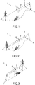
- FIGS 1 to 3 show different modes of operation for removing a felled tree from rough terrain with a cable crane 1.
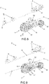
- a in the Figures 4 to 9 The illustrated carriage 2 according to the invention can be used in all of these modes of operation and the traction cable is forced to be spooled out.
- figure 1 shows a tree being roped uphill with the cable crane 1 in 2-cable operation, in which the carriage 2 is pulled with a traction cable 3 on rollers 4 along a carrying cable 5.
- a cable device 6 is provided at the higher end of the supporting cable 5 and pulls the tree together with the carriage 2 upwards, with the tree being cabled uphill. Gravity ensures that the empty carriage 2 can be roped down again along the support rope in order to rope up the next tree.
- figure 2 shows the uphill roping of a tree with the cable crane 1 in 3-rope operation, in which the downhill roping of the empty carriage 2 is carried out with the help of an auxiliary rope 7.
- the auxiliary cable 7 is guided from the carriage 2 via a roller 8 at the lower end of the supporting cable 5 parallel to the supporting cable 5, or via another path, to the cable device 6 and driven by it.
- figure 3 shows the downhill abseiling of a tree with the cable crane 1 in 3-cable operation, in which the cable winch 6 is arranged at the lower end of the support cable 5, which is why the auxiliary cable 7 is short and the traction cable 3 is long.
- the carriage 2 shown essentially consists of a lower carriage part 9 and two upper carriage parts 10 .
- the lower part 9 of the carriage hangs on the two upper parts 10 of the carriage.
- a hydraulic oil tank and a hydraulic pump is arranged, which is driven by the rollers 4 and loads a pressure accumulator, which is arranged in the carriage lower part 9 and supplies the hydraulic clamps and the locking cylinder.
- a traction rope clamp 12 for clamping the traction rope 3 and an auxiliary rope clamp 16 for clamping the auxiliary rope 7 are provided as hydraulic clamps.
- the figure 8 shows the carriage 2, which is operated in 2-rope operation uphill or downhill with forced spooling of the traction rope 3.
- the carriage 2 is movably mounted with the rollers 4 on the supporting cable 5 .
- the traction cable 3 is guided through the carriage 2 in such a way that it wraps around a friction disk 13 sufficiently.
- the traction cable 3 is guided in the carriage 2 over the deflection roller 19 and again over the friction disc 13 directed.
- the traction cable 3 is additionally pressed onto the friction disk 13 by two pressure rollers 14, as a result of which the friction between the friction disk 13 and the traction cable 3 is increased even further.
- the friction disc 13 has V-shaped grooves in which the traction cable 3 is guided.
- the friction disc 13 is mounted together with an auxiliary cable drum 15 on an axle in the lower part 9 of the carriage. Between the friction disc 13 and the auxiliary cable drum 15 there is a freewheel with a ratchet mechanism, which allows the rotation of the friction disc 13 in relation to the auxiliary cable drum 15 in one direction and blocks it in the other direction.
- the auxiliary cable drum 15 has teeth on each of its two cheeks. A locking toothing on the cheek of the auxiliary rope drum 15 facing the friction disk 13 serves to lock the auxiliary rope drum 15 by a locking cylinder and a locking segment, which together form the auxiliary rope clamp 16 .
- a chain toothing 17 on the opposite cheek is used to drive the auxiliary cable drum 15 via a chain drive by an electric motor 18.
- the chain drive is designed in two stages to allow sufficient gear reduction between the electric motor 18 and the auxiliary cable drum 15.
- auxiliary cable drum 15 is therefore empty.
- the electric motor 18, correspondingly controlled by a controller of the carriage 2 now drives the auxiliary cable drum 15 via the chain drive, which in turn drives the friction disc 13, as a result of which the traction cable 3 is unwound from the carriage 2.
- the cable crane 1 must pay out the necessary amount of traction cable 3 .
- the electric motor 18 is supplied with the required energy from the battery, which is also located in the carriage 2 .
- the controller is part of a control device for the carriage 2, which can be remotely controlled by an operator on the ground using radio signals.
- the pull cable 3 drives the friction disc 13 in the opposite direction.
- the friction disc 13 drives the auxiliary cable drum 15 and thus the electric motor 18 via the chain drive.
- the electric motor 18 is now controlled by the controller in such a way that it is operated as a generator.
- the current generated thus charges the battery again when the traction cable 3 is pulled.
- the pull of the traction cable 3 is from Rope device 6 accomplished.
- the electric motor 18 is dimensioned in such a way that the battery can be charged solely by the generator operation when the vehicle is pulled in and no additional charging of the battery is necessary.
- the traction rope clamp 12 After pulling the traction rope 3 and lifting the load, the traction rope clamp 12 is closed. Thereafter, the suspension cable clamp 11 is opened and the carriage 2 together with the load is shifted along the suspension cable 5 in the direction of the cable device 6 as the traction cable 3 is pulled further.
- FIGs 4 to 7 and 9 show the same carriage 2 in 3-rope operation.
- another cable the auxiliary cable 7 is guided by the cable device 6 over deflection rollers in circulation in such a way that it is guided from the side of the carriage 2 opposite the traction cable 3 into the carriage 2 and partly wound up on the auxiliary cable drum 15 in the carriage 2 is.
- the traction cable clamp 12 is opened.
- the rope device 6 is pulled on the auxiliary rope 7 and the traction rope 3 is output.
- the auxiliary cable drum 15 is set in rotation.
- the auxiliary rope 7 unwinds from the auxiliary rope drum 15 .
- the friction disc 13 is coupled to the auxiliary cable drum 15 via the freewheel forming an operative connection and is now also driven by the auxiliary cable 7 .
- the traction cable 3 is spooled out by the rotating friction disc 13 .
- the traction cable 3 now drives the friction disk 13 and thus also the auxiliary cable drum 15 via the freewheel, whereby the auxiliary cable 7 is wound up again on the auxiliary cable drum 15 in the carriage 2 .
- the auxiliary rope 7 must be released from the rope device 6.
- the traction rope 3 is first fastened to a tree, for example. Thereafter, the rotation of the auxiliary cable drum 15 is blocked by engagement of the blocking segment in the locking teeth on one side of the auxiliary cable drum 15 . Now the cable clamp 12 is opened and the carriage 2 is moved with the train on the auxiliary cable 7 along the supporting cable 5 in the direction of the auxiliary cable 7 .
- the friction disc 13 is driven by an electric motor. Only a low spooling force is required for this type of operation.
- the electric motor 18 can be dimensioned correspondingly small.
- the power of the electric motor 18 can be 5,000 watts. This mode of operation is in figure 8 shown.
- the friction disk 13 When roping uphill in 3-rope operation, the friction disk 13 is driven either by the electric motor 18 or via the auxiliary rope 7, depending on the required ejection force and ejection length. Flushing with drive via the auxiliary rope 7 is in figure 9 shown.
- the auxiliary rope When roping uphill in 3-rope operation with electrical flushing, the auxiliary rope is not attached to the auxiliary rope drum 15, but to the lower part 9 of the carriage itself 7 rolled up on the auxiliary cable drum 15 and initially unwound the traction cable 3 by being driven by the auxiliary cable 7 .
- the friction disk 13 When abseiling downhill or on level ground, the friction disk 13 is preferably driven via the auxiliary cable 7 . If the unwinding force is sufficient when driven by the electric motor 18, the friction disc 13 can also be driven by an electric motor when roping downhill or when roping on the level, with the auxiliary rope 7 then not being attached to the auxiliary rope drum 15 but to the lower part 9 of the carriage itself in this mode of operation.
- the forced spooling of the traction cable 3 can be driven, insofar as a very high spooling force is required, which cannot be applied by the auxiliary cable 7 alone, also in combination with a simultaneous drive by the auxiliary cable 7 and the electric motor 18 .
- the electric motor 18 and the auxiliary cable drum 15 are jointly engaged with the friction disc 13 in order to unwind the traction cable 3 . It is particularly advantageous that the electric motor 18 can be switched on at any time by radio remote control and the spooling force can thus be further increased.
- the carriage 2 thus provides a solution that universally offers a suitable forced spooling out of the traction cable 3 for every operating case with the spooling force and spooling speed sufficient for each operating case.
- the electric motor drive is primarily intended for uphill ropes. It can thus be dimensioned small, whereby the weight of the carriage 2 is reduced.
- the drive with the auxiliary rope7 is preferable for the intended for downhill rappelling, where a high spooling force is required and a third rope is required for roping.
- the friction discs are also driven directly by the electric motor, and not via the auxiliary cable drum as an intermediate link. Furthermore, the power transmission between the electric motor and the auxiliary cable drum or friction disk could take place with the aid of a chain, a belt or a gear drive. Depending on the reduction required, the drives can be single-stage or multi-stage.
- the motor drive of the friction disc or the auxiliary cable drum can also be provided by an internal combustion engine or a hydraulic motor.
- the hydraulic motor can be fed by a hydraulic pump directly or via a pressure accumulator, the hydraulic pump being driven by an electric motor or internal combustion engine or, when using a pressure accumulator, can also be driven via the friction disc when the traction cable is pulled.
- the auxiliary cable drum and the friction disc can also be rigidly connected to one another or coupled in a torque-proof manner or be designed to be coupled in a detachable manner. You can also be designed as a common individual component, ie in one piece.
- a clutch that can be switched by radio signal or a switchable freewheel can also be arranged between the friction disc and the auxiliary cable drum. This makes it possible to decouple the friction disc and the auxiliary rope drum and to wind up the auxiliary rope on the auxiliary rope drum using a motor. This eliminates the time-consuming manual spooling or mechanical spooling by pulling out the traction cable while locking the auxiliary cable drum at the same time.
- the auxiliary cable drum or friction disc can also be driven by a hub motor. As a result, a particularly compact design of the carriage is advantageously achieved.
- FIG 10 shows schematically the essential parts of a carriage 20 according to a second embodiment of the invention, specifically in 3-rope operation, which is mainly used when abseiling downhill.
- the carriage 20 includes a cable drum 21 with three compartments, namely a hoist cable compartment 22, a traction cable compartment 23 and an auxiliary cable compartment 24.
- three cable drums can also be arranged in the carriage 20, which are coupled to one another in such a way that the Rotational movement of a drum each causes a rotational movement of the other drums.
- the three drums are advantageously on a common axis. However, they can also be mounted on different axes and connected to one another via drives.
- the carriage 20 has a suspension cable clamp 11 for fixing the carriage 20 to the suspension cable 5, as well as a brake 25 for the cable drum 21.
- the carriage 20 also has a motor drive for the cable drum 21, preferably an electric drive, which drives the cable drum 21 can also be driven directly via a chain drive, a belt drive, a gear drive or, for example, as a hub motor.
- the motor drive is designed as an electric motor 18 in the hollow shaft of the cable drum 21 .
- a hoisting rope 26 of the carriage 20 is used to tighten and lift the load to the carriage 20.
- the carriage 20 With the traction rope 3 and the auxiliary rope 7, the carriage 20 is moved along the support rope 5 on the one hand.
- the two ropes are also used for unwinding and pulling or lifting the load to the carriage 20.
- the carriage 20 is first moved with the suspension cable clamp 11 open and the brake 25 closed by the traction cable 3 and the auxiliary cable 7 along the suspension cable 5 to the appropriate point where the load is to be tightened and lifted. Thereafter, the suspension cable clamp 11 is closed and the carriage 20 is thus fixed to the suspension cable 5 .
- the brake 25 is now opened and the cable drum 21 is rotated by pulling on the auxiliary cable 7 and the simultaneous release of the cable 3 by the cable device 6, whereby the hoist cable 26 is spooled out and the cable 3 is wound up in the cable compartment 23 or the cable drum.
- the pull cable 3 is now pulled in by the cable device 6, causing the cable drum 21 in the carriage 20 to rotate in the opposite direction, so that the hoist cable 26 and auxiliary cable 7 are pulled in and wound up on the cable drum 21.
- the brake 25 is now closed. The load on the carriage 20 is thus fixed.
- the rope clamp 11 is opened and the carriage 20 is pulled downhill with the auxiliary rope 7, when roping uphill with the pull rope 3 to the rope device 6, with the other rope having to be spent sufficiently and the load also has to brake when roping downhill.
- FIG 11 shows schematically only the cable drum 21, the hoist cable 26, auxiliary cable 7 and traction cable 3, and the electric motor 18 to illustrate the cable routing in the carriage 20.
- the rope drum is a one-piece rope drum 21 with three compartments for the individual ropes executed, namely the hoisting cable compartment 22, the auxiliary cable compartment 23 and the traction cable compartment 24, in which the respective cables are spatially separated from one another but coupled to one another and spooled together.
- the carriage 20 can now advantageously also be operated without an auxiliary rope 7 in 2-rope operation, which is primarily used when roping uphill, with the electric motor 18 now driving the rope drum 21 for flushing out the hoist rope 26 .
- the traction cable 3 is also wound up on the cable drum 21 in the associated traction cable compartment 24 .
- the hauling rope 3 is now pulled with the carriage 20 fixed to the carrying rope 5 , so that the hauling rope 3 is unwound from the rope drum 21 .
- the forced rotation of the cable drum 21 now winds up the hoist cable 26 on the cable drum 21 and pulls or lifts the load to the carriage 20.
- the arrangement of the cable compartments is variable.
- the hoisting rope compartment can also be located on one side of the rope drum, the traction rope compartment in the middle and the auxiliary rope compartment on the other side.
- the electric motor 18 is arranged in the hollow shaft of the cable drum 21.
- a gear for example a multi-stage planetary gear, is advantageously arranged between the electric motor 18 and the cable drum 21 .
- the electric motor 18 is also used in this embodiment as a generator when it is pulled in and thus recharges the battery.
- the electric motor or another motor can also be arranged outside the cable drum 21 in the carriage 20 and can drive the cable drum 21, for example via a chain, belt or gear drive.
- an internal combustion engine or a hydraulic motor can also be used as the drive motor.
- a traction cable clamp can also be provided in the carriage 20, which fixes the traction cable 3 in the carriage 20 so that it cannot be unwound or wound up on the cable drum 21.
- the carriage 2 has a brake on the traction cable 3, as is the case, for example, with an in figure 9 drum brake 27 shown is realized.
- a sag occurs in the traction cable 3 between the carriage 2 and the cable crane 1, also known as a rope bag.
- the suspension cable clamp 11 With the help of the suspension cable clamp 11, the descent of the carriage 2 on the suspension cable 5 is terminated and the carriage 2 is clamped to the traction cable 3.
- this sagging of the traction cable 3 is reduced, as a result of which the cable tension in the traction cable 3 between the carriage 2 and cable crane 1 increases.
- the drum brake 27 is provided Friction disc 13 brakes directly and requires significantly less pressure oil.
- the brake could also be installed at any other point in the drive train for unwinding the traction cable 3, for example directly on the motor shaft, in particular as an electromagnetic brake or one of the shafts of the chain drive or the auxiliary cable drum 15.
- the braking function could also be performed by the electric motor 18 itself , but here the braking torque at standstill is limited in time, since there is no cooling if the motor shaft is not rotating.
Landscapes
- Engineering & Computer Science (AREA)
- Mechanical Engineering (AREA)
- Life Sciences & Earth Sciences (AREA)
- Biodiversity & Conservation Biology (AREA)
- Ecology (AREA)
- Forests & Forestry (AREA)
- Environmental Sciences (AREA)
- Jib Cranes (AREA)
- Carriers, Traveling Bodies, And Overhead Traveling Cranes (AREA)
- Unwinding Of Filamentary Materials (AREA)
- Storing, Repeated Paying-Out, And Re-Storing Of Elongated Articles (AREA)
Claims (13)
- Chariot (2 ; 20) d'une grue à câbles (1) pour le transport de charges le long d'un câble porteur (5) de la grue à câbles (1), lequel chariot (2 ; 20), qui est tiré dans un fonctionnement à 2 câbles par un câble de traction (3) ainsi que dans un fonctionnement à 3 câbles par un câble auxiliaire (7) le long du câble porteur (5) d'un dispositif de câbles (6) de la grue à câbles (1), comporte un moteur pour le déroulement du câble de traction (3) ou d'un câble de levage (26) hors du chariot, ainsi qu'un disque de friction (13) qui est prévu pour le mouvement de déroulement du câble de traction (3) et/ou un tambour de câble de levage (22) prévu pour le mouvement de déroulement du câble de levage (26) qui sont entraînés directement ou indirectement par le moteur, caractérisé en ce que ce chariot (2 ; 20) comporte un tambour de câble auxiliaire (15 ; 24) pour le déroulement du câble auxiliaire (7) en fonctionnement à 3 câbles et que le tambour de câble auxiliaire (15 ; 24) est prévu en liaison active avec le disque de friction (13) et/ou le tambour de câble de levage (22) et entraîné par le câble auxiliaire (7) en plus ou à la place du moteur pour le déroulement du câble de traction (3) et/ou du câble de levage (26).
- Chariot (2) selon la revendication 1, caractérisé en ce que le moteur et le tambour de câble auxiliaire (15) sont prévus en prise ensemble avec le disque de friction (13) pour le déroulement du câble de traction (3).
- Chariot (2; 20) selon la revendication 1, caractérisé en ce que le moteur est configuré en liaison active avec le tambour de câble auxiliaire (15 ; 24) pour le déroulement du câble auxiliaire (7).
- Chariot (2) selon la revendication 3, caractérisé en ce que sont prévus un serre-câble de traction (12) pour le serrage du câble de traction (3) et un serre-câble auxiliaire (16) pour le blocage de la rotation du tambour à câble auxiliaire (15), le serre-câble de traction (12) étant bloqué et le serre-câble auxiliaire (16) étant ouvert lors du déroulement du câble auxiliaire (7).
- Chariot (2 ; 20) selon une des revendications 1 à 4, caractérisé en ce que le moteur est constitué par un moteur électrique (18) et en particulier par un moteur à moyeu.
- Chariot (2) selon une des revendications 1 à 5, caractérisé en ce que le moteur est mis en liaison active avec le disque de friction (13) et/ou le tambour de câble auxiliaire (15) par une transmission à chaîne, une transmission à courroie ou un engrenage.
- Chariot (2) selon une des revendications 1 à 6, caractérisé en ce qu'est prévu un dispositif de commande contrôlable par des signaux radio qui est configuré pour l'accouplement et le désaccouplement d'un raccord commutable entre le disque de friction (13) et le tambour de câble auxiliaire (15).
- Chariot (2) selon une des revendications 1 à 6, caractérisé en ce que le disque de friction (13) et le tambour de câble auxiliaire (15) sont formés d'une pièce.
- Chariot (2) selon une des revendications 1 à 6, caractérisé en ce que le disque de friction (15) présente une rainure en forme de V et au moins un rouleau presseur (14) pour le guidage par friction du câble de traction (3).
- Chariot (20) selon la revendication 1, caractérisé en ce qu'un tambour de câble de traction (23) est prévu pour le déroulement du câble de traction (3).
- Chariot (20) selon une la revendication 10, caractérisé en ce que le tambour de câble de traction (23), le tambour de câble auxiliaire (24) et le tambour de câble de levage (22) sont formés d'une pièce.
- Chariot (2) selon une des revendications 1 à 11, caractérisé en ce qu'un frein, en particulier un frein à tambour (27), est prévu dans la chaîne d'entrainement pour le déroulement du câble de traction (3), pour empêcher en descente un retrait du câble de traction (3) en direction de la grue à câbles (1) sous l'effet de la pesanteur, avec un chariot (2) fixé au câble de traction (5) avec un serre-câble de traction (11).
- Chariot (2) selon la revendication 12, caractérisé en ce que le frein à tambour (27) est configuré pour le freinage du disque de friction (13).
Applications Claiming Priority (2)
| Application Number | Priority Date | Filing Date | Title |
|---|---|---|---|
| ATA50489/2018A AT521032B1 (de) | 2018-06-19 | 2018-06-19 | Universallaufwagen mit Zwangsausspulung des Zugseils beziehungsweise des Hubseiles im 2- und 3-Seilbetrieb |
| PCT/EP2019/065965 WO2019243302A1 (fr) | 2018-06-19 | 2019-06-18 | Chariot universel comprenant un déroulement par contrainte du câble de traction ou du câble de levage dans un fonctionnement à 2 et à 3 câbles |
Publications (2)
| Publication Number | Publication Date |
|---|---|
| EP3810541A1 EP3810541A1 (fr) | 2021-04-28 |
| EP3810541B1 true EP3810541B1 (fr) | 2023-01-25 |
Family
ID=66998403
Family Applications (1)
| Application Number | Title | Priority Date | Filing Date |
|---|---|---|---|
| EP19731976.7A Active EP3810541B1 (fr) | 2018-06-19 | 2019-06-18 | Chariot universel comprenant un déroulement par contrainte du câble de traction ou du câble de levage dans un fonctionnement à 2 et à 3 câbles |
Country Status (5)
| Country | Link |
|---|---|
| EP (1) | EP3810541B1 (fr) |
| JP (1) | JP7367011B2 (fr) |
| AT (1) | AT521032B1 (fr) |
| CL (1) | CL2020003035A1 (fr) |
| WO (1) | WO2019243302A1 (fr) |
Families Citing this family (14)
| Publication number | Priority date | Publication date | Assignee | Title |
|---|---|---|---|---|
| AT523714B1 (de) | 2020-06-03 | 2021-11-15 | Mm Forsttechnik Gmbh | Laufwagen mit Greiferbetriebsmodus |
| JP7238865B2 (ja) * | 2020-07-28 | 2023-03-14 | トヨタ自動車株式会社 | 集材方法および集材システム |
| IT202000025798A1 (it) * | 2020-10-30 | 2022-04-30 | Leitalpin Gmbh Srl | Carrello automotore per gru a fune in particolare per il trasporto di materiale come per esempio legno e simile e un impianto funiviario utilizzante un carrello automotore |
| CN113243275B (zh) * | 2021-04-19 | 2022-10-14 | 浙江海聚智能装备科技有限公司 | 一种竹子采伐机器人 |
| AT524983B1 (de) * | 2021-05-12 | 2023-04-15 | Gebrueder Ladstaetter Kg | Laufwagen für einen Seilkran |
| CN113501456A (zh) * | 2021-07-28 | 2021-10-15 | 上海电气风电集团股份有限公司 | 吊运工装 |
| SE2151284A1 (en) * | 2021-10-21 | 2023-03-21 | Komatsu Forest Ab | Self-driving log forwarder shuttle |
| CN114793816B (zh) * | 2022-04-29 | 2024-01-09 | 安徽理工大学 | 一种卷扬拖拉机 |
| CN115159366B (zh) * | 2022-07-26 | 2023-09-01 | 江苏新均力重工有限公司 | 一种大型钢结构支架悬吊施工设备及吊装方法 |
| US20240191978A1 (en) * | 2022-12-09 | 2024-06-13 | Ark Inventive LLC | Target system |
| CN115991431B (zh) * | 2023-03-24 | 2023-05-16 | 济宁四通工程机械有限公司 | 一种起重机液压控制系统 |
| WO2025122135A1 (fr) * | 2023-12-04 | 2025-06-12 | Ark Inventive LLC | Système de cible |
| CN118345711B (zh) * | 2024-05-22 | 2026-07-07 | 广西路桥工程集团有限公司 | 一种自行式支索器传动机构、自行式支索器及缆吊系统 |
| CN119911298B (zh) * | 2025-04-01 | 2025-06-17 | 中铁二局集团有限公司 | 一种多索道协同运输系统及其施工方法和使用方法 |
Family Cites Families (11)
| Publication number | Priority date | Publication date | Assignee | Title |
|---|---|---|---|---|
| US3523615A (en) * | 1968-01-17 | 1970-08-11 | Madill Ltd S | Cable hoisting and hauling apparatus |
| US4127197A (en) * | 1977-03-24 | 1978-11-28 | Dumont Eston A | Dual-purpose skyline log-yarding carriage |
| US4453642A (en) * | 1981-03-05 | 1984-06-12 | Danebo Parts And Equipment Inc. | Carriage-mounted skidding line take-up apparatus |
| JPS58188256U (ja) * | 1983-03-10 | 1983-12-14 | イワフジ工業株式会社 | 架空索用リモ−トコントロ−ル搬器 |
| AT381686B (de) * | 1983-12-07 | 1986-11-10 | Hinteregger R Masch | Hydraulischer seilausspulantrieb fuer einen seilkran |
| CA1219542A (fr) * | 1984-12-27 | 1987-03-24 | National Research Council Of Canada | Mototreuil a cable de debardage |
| AU582292B2 (en) * | 1987-01-15 | 1989-03-16 | Kozo Hirano | Radio control aerial automatic carrying system |
| JPH04277195A (ja) * | 1991-02-28 | 1992-10-02 | ▲魚▼谷鉄工株式会社 | 索道用搬器 |
| AT401169B (de) * | 1994-07-19 | 1996-07-25 | Hinteregger Reinhold | Hydraulischer seilausspulantrieb für das hub- bzw. zugseil eines seilkranes |
| JP2012210853A (ja) * | 2011-03-31 | 2012-11-01 | Sumitomo Forestry Co Ltd | 搬器及びこれを使用した上げ荷方法 |
| AT512872B1 (de) | 2012-05-11 | 2015-02-15 | Koller Gmbh | Elektrische Seilausspulung eines Seilkrans |
-
2018
- 2018-06-19 AT ATA50489/2018A patent/AT521032B1/de active
-
2019
- 2019-06-18 EP EP19731976.7A patent/EP3810541B1/fr active Active
- 2019-06-18 JP JP2021520457A patent/JP7367011B2/ja active Active
- 2019-06-18 WO PCT/EP2019/065965 patent/WO2019243302A1/fr not_active Ceased
-
2020
- 2020-11-23 CL CL2020003035A patent/CL2020003035A1/es unknown
Also Published As
| Publication number | Publication date |
|---|---|
| AT521032B1 (de) | 2019-10-15 |
| JP7367011B2 (ja) | 2023-10-23 |
| AT521032A4 (de) | 2019-10-15 |
| WO2019243302A1 (fr) | 2019-12-26 |
| CL2020003035A1 (es) | 2021-04-16 |
| EP3810541A1 (fr) | 2021-04-28 |
| JP2021528342A (ja) | 2021-10-21 |
Similar Documents
| Publication | Publication Date | Title |
|---|---|---|
| AT521032B1 (de) | Universallaufwagen mit Zwangsausspulung des Zugseils beziehungsweise des Hubseiles im 2- und 3-Seilbetrieb | |
| DE102018110058A1 (de) | Kran | |
| DE102011122121B3 (de) | Forstseilwinde | |
| EP1394094A2 (fr) | Dispositif d'accumulation pour élément de traction | |
| DE1987883U (de) | Haenge - materialhandhabungsvorrichtung. | |
| DE102011013304A1 (de) | Laufwagen für eine Seillinie zum tragenden Transport von Stückgut | |
| WO1996004779A1 (fr) | Transporteur de charges, notamment d'arbres abattus | |
| AT523714B1 (de) | Laufwagen mit Greiferbetriebsmodus | |
| DE102020117578B4 (de) | Verfahren sowie vorspannvorrichtung für hubseiltrommeln | |
| AT512872B1 (de) | Elektrische Seilausspulung eines Seilkrans | |
| EP2574588A1 (fr) | Câble-grue | |
| EP0161437B1 (fr) | Grue à câble | |
| AT524983B1 (de) | Laufwagen für einen Seilkran | |
| DE1812172B2 (de) | An einem Lastfahrzeug befindliche Vorrichtung zur Betätigung einer Ladebordwand | |
| AT381686B (de) | Hydraulischer seilausspulantrieb fuer einen seilkran | |
| AT527941B1 (de) | Laufwagen für eine Seilkrananlage | |
| DE102018105276A1 (de) | Verfahren zum Einbringen von Spanngliedern in einen Turm, Montagevorrichtung, Abtrommelvorrichtung und Adaptervorrichtung | |
| DE69307324T2 (de) | Laufkatze | |
| DE102013113574A1 (de) | Hubgerüst mit hydraulikfreiem Hubantrieb | |
| AT401169B (de) | Hydraulischer seilausspulantrieb für das hub- bzw. zugseil eines seilkranes | |
| EP4003894B1 (fr) | Installation de tambour à câble pour une grue à câble | |
| DE3443191C2 (de) | Stoßschutzeinrichtung für das Abbremsen von Schiffen in Schleusenanlagen | |
| DE112014003094B4 (de) | Treibtrommeltrieb | |
| AT233769B (de) | Laufkatze | |
| AT409124B (de) | Seilausspulvorrichtung für das hub- bzw. zugseil eines seilkranes |
Legal Events
| Date | Code | Title | Description |
|---|---|---|---|
| STAA | Information on the status of an ep patent application or granted ep patent |
Free format text: STATUS: UNKNOWN |
|
| STAA | Information on the status of an ep patent application or granted ep patent |
Free format text: STATUS: THE INTERNATIONAL PUBLICATION HAS BEEN MADE |
|
| PUAI | Public reference made under article 153(3) epc to a published international application that has entered the european phase |
Free format text: ORIGINAL CODE: 0009012 |
|
| STAA | Information on the status of an ep patent application or granted ep patent |
Free format text: STATUS: REQUEST FOR EXAMINATION WAS MADE |
|
| 17P | Request for examination filed |
Effective date: 20210111 |
|
| AK | Designated contracting states |
Kind code of ref document: A1 Designated state(s): AL AT BE BG CH CY CZ DE DK EE ES FI FR GB GR HR HU IE IS IT LI LT LU LV MC MK MT NL NO PL PT RO RS SE SI SK SM TR |
|
| AX | Request for extension of the european patent |
Extension state: BA ME |
|
| DAV | Request for validation of the european patent (deleted) | ||
| DAX | Request for extension of the european patent (deleted) | ||
| GRAP | Despatch of communication of intention to grant a patent |
Free format text: ORIGINAL CODE: EPIDOSNIGR1 |
|
| STAA | Information on the status of an ep patent application or granted ep patent |
Free format text: STATUS: GRANT OF PATENT IS INTENDED |
|
| INTG | Intention to grant announced |
Effective date: 20220902 |
|
| GRAS | Grant fee paid |
Free format text: ORIGINAL CODE: EPIDOSNIGR3 |
|
| GRAA | (expected) grant |
Free format text: ORIGINAL CODE: 0009210 |
|
| STAA | Information on the status of an ep patent application or granted ep patent |
Free format text: STATUS: THE PATENT HAS BEEN GRANTED |
|
| AK | Designated contracting states |
Kind code of ref document: B1 Designated state(s): AL AT BE BG CH CY CZ DE DK EE ES FI FR GB GR HR HU IE IS IT LI LT LU LV MC MK MT NL NO PL PT RO RS SE SI SK SM TR |
|
| REG | Reference to a national code |
Ref country code: GB Ref legal event code: FG4D Free format text: NOT ENGLISH |
|
| REG | Reference to a national code |
Ref country code: CH Ref legal event code: EP |
|
| REG | Reference to a national code |
Ref country code: DE Ref legal event code: R096 Ref document number: 502019006872 Country of ref document: DE |
|
| REG | Reference to a national code |
Ref country code: AT Ref legal event code: REF Ref document number: 1545800 Country of ref document: AT Kind code of ref document: T Effective date: 20230215 Ref country code: IE Ref legal event code: FG4D Free format text: LANGUAGE OF EP DOCUMENT: GERMAN |
|
| REG | Reference to a national code |
Ref country code: LT Ref legal event code: MG9D |
|
| REG | Reference to a national code |
Ref country code: NL Ref legal event code: MP Effective date: 20230125 |
|
| PG25 | Lapsed in a contracting state [announced via postgrant information from national office to epo] |
Ref country code: NL Free format text: LAPSE BECAUSE OF FAILURE TO SUBMIT A TRANSLATION OF THE DESCRIPTION OR TO PAY THE FEE WITHIN THE PRESCRIBED TIME-LIMIT Effective date: 20230125 |
|
| P01 | Opt-out of the competence of the unified patent court (upc) registered |
Effective date: 20230614 |
|
| PG25 | Lapsed in a contracting state [announced via postgrant information from national office to epo] |
Ref country code: RS Free format text: LAPSE BECAUSE OF FAILURE TO SUBMIT A TRANSLATION OF THE DESCRIPTION OR TO PAY THE FEE WITHIN THE PRESCRIBED TIME-LIMIT Effective date: 20230125 Ref country code: PT Free format text: LAPSE BECAUSE OF FAILURE TO SUBMIT A TRANSLATION OF THE DESCRIPTION OR TO PAY THE FEE WITHIN THE PRESCRIBED TIME-LIMIT Effective date: 20230525 Ref country code: NO Free format text: LAPSE BECAUSE OF FAILURE TO SUBMIT A TRANSLATION OF THE DESCRIPTION OR TO PAY THE FEE WITHIN THE PRESCRIBED TIME-LIMIT Effective date: 20230425 Ref country code: LV Free format text: LAPSE BECAUSE OF FAILURE TO SUBMIT A TRANSLATION OF THE DESCRIPTION OR TO PAY THE FEE WITHIN THE PRESCRIBED TIME-LIMIT Effective date: 20230125 Ref country code: LT Free format text: LAPSE BECAUSE OF FAILURE TO SUBMIT A TRANSLATION OF THE DESCRIPTION OR TO PAY THE FEE WITHIN THE PRESCRIBED TIME-LIMIT Effective date: 20230125 Ref country code: HR Free format text: LAPSE BECAUSE OF FAILURE TO SUBMIT A TRANSLATION OF THE DESCRIPTION OR TO PAY THE FEE WITHIN THE PRESCRIBED TIME-LIMIT Effective date: 20230125 Ref country code: ES Free format text: LAPSE BECAUSE OF FAILURE TO SUBMIT A TRANSLATION OF THE DESCRIPTION OR TO PAY THE FEE WITHIN THE PRESCRIBED TIME-LIMIT Effective date: 20230125 |
|
| PG25 | Lapsed in a contracting state [announced via postgrant information from national office to epo] |
Ref country code: SE Free format text: LAPSE BECAUSE OF FAILURE TO SUBMIT A TRANSLATION OF THE DESCRIPTION OR TO PAY THE FEE WITHIN THE PRESCRIBED TIME-LIMIT Effective date: 20230125 Ref country code: PL Free format text: LAPSE BECAUSE OF FAILURE TO SUBMIT A TRANSLATION OF THE DESCRIPTION OR TO PAY THE FEE WITHIN THE PRESCRIBED TIME-LIMIT Effective date: 20230125 Ref country code: IS Free format text: LAPSE BECAUSE OF FAILURE TO SUBMIT A TRANSLATION OF THE DESCRIPTION OR TO PAY THE FEE WITHIN THE PRESCRIBED TIME-LIMIT Effective date: 20230525 Ref country code: GR Free format text: LAPSE BECAUSE OF FAILURE TO SUBMIT A TRANSLATION OF THE DESCRIPTION OR TO PAY THE FEE WITHIN THE PRESCRIBED TIME-LIMIT Effective date: 20230426 Ref country code: FI Free format text: LAPSE BECAUSE OF FAILURE TO SUBMIT A TRANSLATION OF THE DESCRIPTION OR TO PAY THE FEE WITHIN THE PRESCRIBED TIME-LIMIT Effective date: 20230125 |
|
| REG | Reference to a national code |
Ref country code: DE Ref legal event code: R097 Ref document number: 502019006872 Country of ref document: DE |
|
| PG25 | Lapsed in a contracting state [announced via postgrant information from national office to epo] |
Ref country code: SM Free format text: LAPSE BECAUSE OF FAILURE TO SUBMIT A TRANSLATION OF THE DESCRIPTION OR TO PAY THE FEE WITHIN THE PRESCRIBED TIME-LIMIT Effective date: 20230125 Ref country code: RO Free format text: LAPSE BECAUSE OF FAILURE TO SUBMIT A TRANSLATION OF THE DESCRIPTION OR TO PAY THE FEE WITHIN THE PRESCRIBED TIME-LIMIT Effective date: 20230125 Ref country code: EE Free format text: LAPSE BECAUSE OF FAILURE TO SUBMIT A TRANSLATION OF THE DESCRIPTION OR TO PAY THE FEE WITHIN THE PRESCRIBED TIME-LIMIT Effective date: 20230125 Ref country code: DK Free format text: LAPSE BECAUSE OF FAILURE TO SUBMIT A TRANSLATION OF THE DESCRIPTION OR TO PAY THE FEE WITHIN THE PRESCRIBED TIME-LIMIT Effective date: 20230125 Ref country code: CZ Free format text: LAPSE BECAUSE OF FAILURE TO SUBMIT A TRANSLATION OF THE DESCRIPTION OR TO PAY THE FEE WITHIN THE PRESCRIBED TIME-LIMIT Effective date: 20230125 |
|
| PG25 | Lapsed in a contracting state [announced via postgrant information from national office to epo] |
Ref country code: SK Free format text: LAPSE BECAUSE OF FAILURE TO SUBMIT A TRANSLATION OF THE DESCRIPTION OR TO PAY THE FEE WITHIN THE PRESCRIBED TIME-LIMIT Effective date: 20230125 |
|
| PLBE | No opposition filed within time limit |
Free format text: ORIGINAL CODE: 0009261 |
|
| STAA | Information on the status of an ep patent application or granted ep patent |
Free format text: STATUS: NO OPPOSITION FILED WITHIN TIME LIMIT |
|
| 26N | No opposition filed |
Effective date: 20231026 |
|
| PG25 | Lapsed in a contracting state [announced via postgrant information from national office to epo] |
Ref country code: MC Free format text: LAPSE BECAUSE OF FAILURE TO SUBMIT A TRANSLATION OF THE DESCRIPTION OR TO PAY THE FEE WITHIN THE PRESCRIBED TIME-LIMIT Effective date: 20230125 |
|
| PG25 | Lapsed in a contracting state [announced via postgrant information from national office to epo] |
Ref country code: SI Free format text: LAPSE BECAUSE OF FAILURE TO SUBMIT A TRANSLATION OF THE DESCRIPTION OR TO PAY THE FEE WITHIN THE PRESCRIBED TIME-LIMIT Effective date: 20230125 Ref country code: MC Free format text: LAPSE BECAUSE OF FAILURE TO SUBMIT A TRANSLATION OF THE DESCRIPTION OR TO PAY THE FEE WITHIN THE PRESCRIBED TIME-LIMIT Effective date: 20230125 |
|
| REG | Reference to a national code |
Ref country code: BE Ref legal event code: MM Effective date: 20230630 |
|
| GBPC | Gb: european patent ceased through non-payment of renewal fee |
Effective date: 20230618 |
|
| PG25 | Lapsed in a contracting state [announced via postgrant information from national office to epo] |
Ref country code: LU Free format text: LAPSE BECAUSE OF NON-PAYMENT OF DUE FEES Effective date: 20230618 |
|
| REG | Reference to a national code |
Ref country code: IE Ref legal event code: MM4A |
|
| PG25 | Lapsed in a contracting state [announced via postgrant information from national office to epo] |
Ref country code: LU Free format text: LAPSE BECAUSE OF NON-PAYMENT OF DUE FEES Effective date: 20230618 |
|
| PG25 | Lapsed in a contracting state [announced via postgrant information from national office to epo] |
Ref country code: IE Free format text: LAPSE BECAUSE OF NON-PAYMENT OF DUE FEES Effective date: 20230618 |
|
| PG25 | Lapsed in a contracting state [announced via postgrant information from national office to epo] |
Ref country code: IE Free format text: LAPSE BECAUSE OF NON-PAYMENT OF DUE FEES Effective date: 20230618 Ref country code: GB Free format text: LAPSE BECAUSE OF NON-PAYMENT OF DUE FEES Effective date: 20230618 |
|
| PG25 | Lapsed in a contracting state [announced via postgrant information from national office to epo] |
Ref country code: FR Free format text: LAPSE BECAUSE OF NON-PAYMENT OF DUE FEES Effective date: 20230630 Ref country code: BE Free format text: LAPSE BECAUSE OF NON-PAYMENT OF DUE FEES Effective date: 20230630 |
|
| PG25 | Lapsed in a contracting state [announced via postgrant information from national office to epo] |
Ref country code: BG Free format text: LAPSE BECAUSE OF FAILURE TO SUBMIT A TRANSLATION OF THE DESCRIPTION OR TO PAY THE FEE WITHIN THE PRESCRIBED TIME-LIMIT Effective date: 20230125 |
|
| PG25 | Lapsed in a contracting state [announced via postgrant information from national office to epo] |
Ref country code: BG Free format text: LAPSE BECAUSE OF FAILURE TO SUBMIT A TRANSLATION OF THE DESCRIPTION OR TO PAY THE FEE WITHIN THE PRESCRIBED TIME-LIMIT Effective date: 20230125 |
|
| PGFP | Annual fee paid to national office [announced via postgrant information from national office to epo] |
Ref country code: DE Payment date: 20250618 Year of fee payment: 7 |
|
| PGFP | Annual fee paid to national office [announced via postgrant information from national office to epo] |
Ref country code: AT Payment date: 20250625 Year of fee payment: 7 |
|
| PG25 | Lapsed in a contracting state [announced via postgrant information from national office to epo] |
Ref country code: CY Free format text: LAPSE BECAUSE OF FAILURE TO SUBMIT A TRANSLATION OF THE DESCRIPTION OR TO PAY THE FEE WITHIN THE PRESCRIBED TIME-LIMIT; INVALID AB INITIO Effective date: 20190618 |
|
| PG25 | Lapsed in a contracting state [announced via postgrant information from national office to epo] |
Ref country code: HU Free format text: LAPSE BECAUSE OF FAILURE TO SUBMIT A TRANSLATION OF THE DESCRIPTION OR TO PAY THE FEE WITHIN THE PRESCRIBED TIME-LIMIT; INVALID AB INITIO Effective date: 20190618 |
|
| PGFP | Annual fee paid to national office [announced via postgrant information from national office to epo] |
Ref country code: IT Payment date: 20250620 Year of fee payment: 7 |
|
| PGFP | Annual fee paid to national office [announced via postgrant information from national office to epo] |
Ref country code: CH Payment date: 20250701 Year of fee payment: 7 |
|
| PG25 | Lapsed in a contracting state [announced via postgrant information from national office to epo] |
Ref country code: TR Free format text: LAPSE BECAUSE OF FAILURE TO SUBMIT A TRANSLATION OF THE DESCRIPTION OR TO PAY THE FEE WITHIN THE PRESCRIBED TIME-LIMIT Effective date: 20230125 |