EP3810545B1 - Procédé de déshydrogénation d'un milieu porteur d'hydrogène - Google Patents
Procédé de déshydrogénation d'un milieu porteur d'hydrogène Download PDFInfo
- Publication number
- EP3810545B1 EP3810545B1 EP19729273.3A EP19729273A EP3810545B1 EP 3810545 B1 EP3810545 B1 EP 3810545B1 EP 19729273 A EP19729273 A EP 19729273A EP 3810545 B1 EP3810545 B1 EP 3810545B1
- Authority
- EP
- European Patent Office
- Prior art keywords
- hydrogen
- reaction accelerator
- reaction
- carrier medium
- accelerator substance
- Prior art date
- Legal status (The legal status is an assumption and is not a legal conclusion. Google has not performed a legal analysis and makes no representation as to the accuracy of the status listed.)
- Active
Links
Images


Classifications
-
- C—CHEMISTRY; METALLURGY
- C01—INORGANIC CHEMISTRY
- C01B—NON-METALLIC ELEMENTS; COMPOUNDS THEREOF; METALLOIDS OR COMPOUNDS THEREOF NOT COVERED BY SUBCLASS C01C
- C01B3/00—Hydrogen; Gaseous mixtures containing hydrogen; Separation of hydrogen from mixtures containing it; Purification of hydrogen; Reversible storage of hydrogen
- C01B3/0005—Reversible storage of hydrogen, e.g. by hydrogen getters or electrodes
- C01B3/001—Reversible storage of hydrogen, e.g. by hydrogen getters or electrodes characterised by the uptaking media; Treatment thereof
- C01B3/0015—Organic compounds, e.g. liquid organic hydrogen carriers [LOHC] or metalorganic compounds; Solutions thereof
-
- B—PERFORMING OPERATIONS; TRANSPORTING
- B01—PHYSICAL OR CHEMICAL PROCESSES OR APPARATUS IN GENERAL
- B01J—CHEMICAL OR PHYSICAL PROCESSES, e.g. CATALYSIS OR COLLOID CHEMISTRY; THEIR RELEVANT APPARATUS
- B01J19/00—Chemical, physical or physico-chemical processes in general; Their relevant apparatus
- B01J19/0053—Details of the reactor
- B01J19/006—Baffles
-
- B—PERFORMING OPERATIONS; TRANSPORTING
- B01—PHYSICAL OR CHEMICAL PROCESSES OR APPARATUS IN GENERAL
- B01J—CHEMICAL OR PHYSICAL PROCESSES, e.g. CATALYSIS OR COLLOID CHEMISTRY; THEIR RELEVANT APPARATUS
- B01J19/00—Chemical, physical or physico-chemical processes in general; Their relevant apparatus
- B01J19/0053—Details of the reactor
- B01J19/0066—Stirrers
-
- B—PERFORMING OPERATIONS; TRANSPORTING
- B01—PHYSICAL OR CHEMICAL PROCESSES OR APPARATUS IN GENERAL
- B01J—CHEMICAL OR PHYSICAL PROCESSES, e.g. CATALYSIS OR COLLOID CHEMISTRY; THEIR RELEVANT APPARATUS
- B01J21/00—Catalysts comprising the elements, oxides, or hydroxides of magnesium, boron, aluminium, carbon, silicon, titanium, zirconium, or hafnium
- B01J21/18—Carbon
-
- B—PERFORMING OPERATIONS; TRANSPORTING
- B01—PHYSICAL OR CHEMICAL PROCESSES OR APPARATUS IN GENERAL
- B01J—CHEMICAL OR PHYSICAL PROCESSES, e.g. CATALYSIS OR COLLOID CHEMISTRY; THEIR RELEVANT APPARATUS
- B01J23/00—Catalysts comprising metals or metal oxides or hydroxides, not provided for in group B01J21/00
- B01J23/38—Catalysts comprising metals or metal oxides or hydroxides, not provided for in group B01J21/00 of noble metals
- B01J23/40—Catalysts comprising metals or metal oxides or hydroxides, not provided for in group B01J21/00 of noble metals of the platinum group metals
- B01J23/44—Palladium
-
- B—PERFORMING OPERATIONS; TRANSPORTING
- B01—PHYSICAL OR CHEMICAL PROCESSES OR APPARATUS IN GENERAL
- B01J—CHEMICAL OR PHYSICAL PROCESSES, e.g. CATALYSIS OR COLLOID CHEMISTRY; THEIR RELEVANT APPARATUS
- B01J2219/00—Chemical, physical or physico-chemical processes in general; Their relevant apparatus
- B01J2219/00761—Details of the reactor
- B01J2219/00763—Baffles
- B01J2219/00779—Baffles attached to the stirring means
-
- C—CHEMISTRY; METALLURGY
- C01—INORGANIC CHEMISTRY
- C01B—NON-METALLIC ELEMENTS; COMPOUNDS THEREOF; METALLOIDS OR COMPOUNDS THEREOF NOT COVERED BY SUBCLASS C01C
- C01B2203/00—Integrated processes for the production of hydrogen or synthesis gas
- C01B2203/10—Catalysts for performing the hydrogen forming reactions
- C01B2203/1041—Composition of the catalyst
- C01B2203/1047—Group VIII metal catalysts
- C01B2203/1064—Platinum group metal catalysts
Definitions
- the present patent application takes the priorities of the German patent applications DE 10 2018 210 337.2 and DE 10 2018 210 247.3 in use.
- the invention relates to a process for dehydrogenating a hydrogen carrier medium.
- US 2018/0093889 A1 discloses a liquid hydrogen storage medium and a method for storing hydrogen.
- JP 2015-030 653 A discloses a system and method for energy utilization from carbon dioxide.
- US 2017/0166496 A1 discloses a hydrogenation system for aromatic compounds.
- a carrier medium for chemically binding hydrogen is known from EP 1 475 349 A2 known.
- the hydrogen carrier medium is a liquid organic hydride known as a liquid organic hydrogen carrier (LOHC).
- LOHC can be loaded with hydrogen, i.e., hydrogenated. In its hydrogenated form, the hydrogen is chemically bonded to the hydrogen carrier medium.
- the carrier medium is in a loaded state.
- LOHC can be reversibly loaded with hydrogen and unloaded from hydrogen.
- the physicochemical properties of LOHC are highly similar to conventional liquid fuels, allowing pumps and tank vehicles to be used for transport, and containers to be used for storage, of LOHC in the field of fuel logistics. Hydrogen storage in chemically bonded form in an organic liquid allows pressureless storage under normal conditions over long periods of time without significant hydrogen loss.
- LOHC are aromatic compounds with at least one ⁇ -electron system that are converted into the corresponding saturated, alicyclic compounds through catalytic hydrogenation.
- Examples of LOHCs include dibenzyltoluene and benzyltoluene as pure substances, isomeric mixtures, or mixtures of these substances with each other.
- Polycyclic, heteroaromatic compounds with at least one ⁇ -electron system can also serve as LOHCs; these compounds are converted into the corresponding saturated, polycyclic compounds containing heteroatoms such as nitrogen or oxygen by hydrogenation.
- N-ethylcarbazole, N-propylcarbazole, N-isopropylcarbazole, N-butylcarbazole, or mixtures of these substances serve as LOHCs.
- Oligomers or polymers with extended ⁇ -conjugated electron systems can also serve as LOHCs; these compounds are converted into the corresponding saturated compounds by hydrogenation.
- the hydrogen carrier medium i.e., LOHC
- LOHC is dehydrogenated with the addition of heat and in the presence of a catalyst, thereby converting the LOHC into its discharged form.
- hydrogen is released from an organic molecule or from a mixture of organic molecules through a catalyzed dehydrogenation reaction. This means that the hydrogen is released through a material transformation of the at least partially loaded hydrogen carrier medium in a reaction vessel by means of a catalyzed dehydrogenation reaction.
- the release rate i.e. the amount of hydrogen released per unit of time
- the release rate is limited with the methods known from the state of the art. Therefore, dehydrogenation of the hydrogen carrier medium according to the state of the art is possible at temperatures below 250 °C is uneconomical.
- a technically viable release rate of at least 10 standard liters of hydrogen per liter of catalyst volume per minute can only be achieved with state-of-the-art processes if the reaction temperature is above 250 °C.
- the invention is based on the object of improving the release of hydrogen from a hydrogen carrier medium from an economic point of view, so that hydrogen is released in particular with an increased release rate and in particular at reduced temperatures.
- the core of the invention is that, in addition to a metal-containing catalyst material, a metal-free reaction accelerator substance is used to dehydrogenate an at least partially loaded hydrogen carrier medium.
- the hydrogen carrier medium is, in particular, LOHC and, in particular, heteroatom-free.
- the LOHC consists, in particular, exclusively of carbon atoms and hydrogen atoms. It has been found that heteroatom-free LOHC substances are advantageous over substances containing heteroatoms such as nitrogen or boron. Heteroatom-free LOHC substances are chemically very similar to the fuels used today, so that the infrastructure for fuel transport, storage, and distribution can be used for the transport, storage, and distribution of the LOHC substance.
- heteroatom-free LOHC substances are more readily available and can be obtained cost-effectively because these substances can be obtained directly from basic petrochemicals.
- the heteroatom-free carrier media do not have the disadvantage that in the hydrogen-discharged form the melting point is above room temperature, which would make the use of LOHC systems for technical applications difficult.
- the heteroatom-free LOHC substance dibenzyltoluene has a melting point below -35 °C.
- the heteroatom-containing LOHC substance N-ethylcarbazole has a melting point of 70 °C.
- the thermal stability of the heteroatom-free hydrogen carrier media is higher than that of the heteroatom-containing carrier media due to the comparatively more stable carbon-carbon bonds increased.
- the undesirable thermal decomposition reactions are reduced in the heteroatom-free hydrogen carrier medium.
- metal-containing catalysts are catalysts containing the elements platinum, palladium, and/or nickel. Catalysts containing other or additional elements, such as rhodium, iridium, gallium, chromium, iron, cobalt, and/or copper, are also possible. It is essential that the metal-containing catalysts used have the ability to activate LOHC-bound hydrogen, transfer it to the metal-free reaction accelerator substance, and release it from there as elemental hydrogen.
- the metal-containing catalyst is suitable for both transfer hydrogenation and dehydrogenation. For dehydrogenation, the at least partially loaded hydrogen carrier medium is brought into direct contact with the metal-containing catalyst and the metal-free reaction accelerator substance.
- the contacting can take place in a single reaction vessel containing the three components—the hydrogen carrier medium, the catalyst, and the reaction accelerator substance.
- the contacting can also take place stepwise in several reaction vessels, particularly in series.
- Hydrogen is transferred from the hydrogen carrier medium to the reaction accelerator substance, particularly directly.
- the hydrogen can also be transferred in atomic form from the hydrogen carrier medium to the reaction accelerator substance.
- the metal-free reaction accelerator substance has the ability to absorb hydrogen in the presence of a metal-containing catalyst.
- the metal-free reaction accelerator substance also has the ability to rapidly release the absorbed hydrogen at comparatively low temperatures, thereby releasing hydrogen gas.
- the metal-free reaction accelerator substance is, in particular, initially present in a hydrogen-depleted form. By reacting with the loaded hydrogen carrier medium in the presence of the metal-containing catalyst, the metal-free reaction accelerator substance is converted into a hydrogen-enriched form.
- the hydrogen-enriched form of the metal-free reaction accelerator substance differs from the at least partially loaded hydrogen carrier medium.
- the hydrogen-depleted form of the metal-free reaction accelerator substance differs from the at least partially discharged hydrogen carrier medium.
- the metal-free reaction accelerator substance and the hydrogen carrier medium are two different and, in particular, two separate material systems.
- hydrogen is transferred from the at least partially loaded hydrogen carrier medium, i.e., from a first material system, to the hydrogen-depleted form of the metal-free reaction accelerator substance, i.e., to a second material system that differs from the first material system.
- Hydrogen gas which, in particular, has previously been transferred to the metal-free reaction accelerator substance in the hydrogen-depleted form, is then released from the hydrogen-enriched form of the reaction accelerator substance.
- the reaction accelerator substance differs from the hydrogen carrier medium.
- the hydrogen-enriched form of the reaction accelerator substance can release hydrogen as elemental hydrogen gas at lower temperatures and/or higher pressures than the hydrogen carrier medium with the same type and quantity of metal-containing catalyst.
- the intermediate step according to the invention whereby hydrogen is first transferred from the hydrogen carrier medium to the reaction accelerator substance before release, reduces the overall energy expenditure in the process for releasing hydrogen, since the release of hydrogen gas can occur at a lower temperature.
- the additional use of the metal-free reaction accelerator substance enables the release of hydrogen at reduced reaction temperatures with an increased release rate, i.e. an increased reaction rate.
- reaction rate during the dehydrogenation of a hydrogen carrier medium is of crucial importance for the economic viability of the process, since a target amount of hydrogen to be released at a low release rate would require a larger reaction vessel. This would result in additional space requirements and additional costs. This can be avoided by the invention.
- the hydrogen is released as elemental hydrogen in gaseous form from the hydrogen-enriched reaction accelerator substance in intensive contact with the at least
- the hydrogen is initially released from the partially loaded hydrogen carrier medium and the metal-containing catalyst.
- the reaction accelerator substance is converted into the hydrogen-depleted form.
- Hydrogen is then transferred from the hydrogen carrier medium in contact with the metal-containing catalyst to the hydrogen-depleted form of the reaction accelerator substance, forming the hydrogen-enriched form of the reaction accelerator substance.
- Elemental hydrogen is again released in gaseous form from the hydrogen-enriched form of the reaction accelerator substance. This process is ideally repeated until all of the releasable hydrogen from the loaded hydrogen carrier medium is present as elemental hydrogen gas.
- the described processes all take place simultaneously in the reaction vessel. They result in the hydrogen being converted from the hydrogen carrier medium to elemental hydrogen gas at much lower temperatures and/or much faster, i.e., with an increased release rate, compared to hydrogen release without a reaction accelerator.
- reaction accelerator substance having at least one functional group containing oxygen and/or nitrogen has proven to be particularly suitable.
- a process according to claim 4 ensures a technically usable discharge rate at reduced reaction temperatures.
- the technically usable release rate of more than 10 standard liters of hydrogen per liter of catalyst volume per minute is possible at temperatures of less than 250°C, in particular less than 220°C, in particular less than 200°C, in particular less than 180°C, and in particular less than 150°C.
- R 1 and R 2 are, independently of one another, linear or branched alkyl, aryl, or aralkyl groups having one, more than one, or, in polymer structures, a very large number of carbon atoms, which in turn may contain further alcohol functions, but also other functional groups such as nitrogen-containing groups, phosphorus-containing groups, or halogen atoms.
- R 1 and R 2 may, in particular, be bonded to one another in a ring shape, so that the hydrogen-enriched form of the metal-free reaction accelerator substance is a cycloalkanol compound.
- the ring-shaped compound may contain further alcohol functions, but also other functional groups such as nitrogen-containing groups, phosphorus-containing groups, or halogen atoms.
- reaction accelerator substance A corresponding hydrogen-depleted form of this reaction accelerator substance is ketone compounds.
- a reaction accelerator substance has proven particularly advantageous which, in the hydrogen-enriched form, contains oligovinyl alcohols in the general form and/or Polyvinyl alcohols in the general form includes.
- R 3 is in particular a linear or branched alkyl, aryl or aralkyl group with one, several or, in polymer structures, very many carbon atoms, which in turn may contain further alcohol functions, but also other functional groups such as nitrogen-containing groups, phosphorus-containing groups or halogen atoms.
- R 5 is, in particular, independently of R 3 , another linear or branched alkyl, aryl or aralkyl group with one, several or, in polymer structures, very many carbon atoms, which in turn may contain further alcohol functions, but also other functional groups such as nitrogen-containing groups, phosphorus-containing groups or halogen atoms.
- R 6 and R 7 are independently linear or branched alkyl, aryl or aralkyl groups with one, several or, in polymer structures, very many carbon atoms, which in turn contain further amine functions, but also other functional groups such as oxygen-containing groups, phosphorus-containing groups, or halogen atoms.
- R 6 and R 7 can be linked to each other in a ring, so that the hydrogen-enriched form of the reaction accelerator substance is a cycloamine compound.
- the ring-shaped compound can contain additional amine functions, but also other functional groups such as oxygen-containing groups, phosphorus-containing groups, or halogen atoms.
- R 8 can be another linear or branched alkyl, aryl or aralkyl group with one, several or, in polymer structures, very many carbon atoms, which in turn can contain further amine functions, but also other functional groups such as oxygen-containing groups, phosphorus-containing groups or halogen atoms.
- reaction accelerator substance is imine compounds.
- reaction accelerator substance which, in the hydrogen-enriched form, contains oligovinylamines and/or polyvinylamines in the general form has.
- R 9 is a linear or branched alkyl, aryl or aralkyl group with one, several or, in polymer structures, very many carbon atoms, which in turn may contain further amine functions, but also other functional groups such as oxygen-containing groups, phosphorus-containing groups or halogen atoms.
- R 11 can in particular be a further linear or branched alkyl, aryl or aralkyl group with one, several or, in polymer structures, very many carbon atoms, which in turn can contain further amine functions, but also other functional groups such as oxygen-containing groups, phosphorus-containing groups or halogen atoms.
- R 12 and R 13 can each independently be a further linear or branched alkyl, aryl or aralkyl group with one, several or, in polymer structures, very many carbon atoms, which in turn can contain further amine functions, but also other functional groups such as oxygen-containing groups, phosphorus-containing groups or halogen atoms.
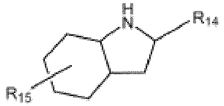
- a reaction accelerator substance has also proven suitable, which in the hydrogen-enriched form is a dehydrogenatable hetero-alicyclic compound in the general form or or or or represents.
- R 14 and/or R 16 can be a hydrogen atom, a linear or branched alkyl, aryl or aralkyl group with one, several or, in polymer structures, very many carbon atoms, which in turn can contain further amine functions, but also other functional groups such as oxygen-containing groups, phosphorus-containing groups or halogen atoms.
- R 15 can in particular be one or more linear or branched alkyl, aryl or aralkyl groups attached at any position on the ring with one, more or, in polymer structures, very many carbon atoms, which in turn can contain further amine functions, but also other functional groups such as oxygen-containing groups, phosphorus-containing groups or halogen atoms or can contain an oxygen-, nitrogen- or phosphorus-containing functional group or a halogen atom.
- a method using a reaction accelerator substance according to claim 10 has proven advantageous and, in particular, enables simplified separation of the reaction accelerator substance from the released hydrogen gas. It is essential that the vapor pressure of the reaction accelerator is higher, and in particular significantly higher, than the vapor pressure of the hydrogen carrier medium, particularly under the reaction conditions of hydrogen release, i.e., the reaction temperature and the reaction pressure.
- the reaction accelerator substance is fed into the reaction vessel in liquid and/or gaseous form and made available there.
- the reaction accelerator substance is discharged from the reaction vessel in gaseous form together with the released hydrogen.
- the reaction accelerator substance can be condensed out of the exhaust stream and returned to the reaction vessel. When the metal-free reaction accelerator substance condenses, hydrogen of high purity remains in the gas phase.
- the vapor pressure of the reaction accelerator substance is more than twice as high, in particular more than five times as high, in particular more than ten times as high, in particular at least 50 times as high, in particular at least 100 times as high, and in particular at least 200 times as high as the vapor pressure of the hydrogen carrier medium.
- the LOHC compounds have a vapor pressure of less than 1 mbar at room temperature. It is advantageous if the reaction accelerator substance has a vapor pressure of at least 10 mbar at room temperature. This is the case, for example, for the reaction accelerators acetone, 2-butanone, 2-pentanone, cyclopentanone, and/or cyclohexanone.
- the vapor pressure of the LOHC substance dibenzyltoluene is less than 1 mbar at room temperature.
- the vapor pressure of the reaction accelerator substance acetone is 246 mbar at room temperature.
- a simplified hydrogen release can be achieved by the vapor pressure of the reaction accelerator substance being lower, and in particular significantly lower, than the vapor pressure of the hydrogen carrier medium, particularly under the conditions of the hydrogen release process.
- the metal-free reaction accelerator substance is initially added to the reaction vessel; the released hydrogen leaves the reaction vessel in gaseous form together with a certain amount of hydrogen carrier medium, which condenses out of the product stream. so that hydrogen remains in high purity.
- a reaction accelerator substance with a high molecular weight has a low vapor pressure.
- the reaction accelerator substance is, for example, a high-molecular-weight liquid or a high-molecular-weight compound dissolved in the hydrogen carrier medium, such as a liquid or soluble polymer.
- the vapor pressures in the reaction vessel vary under reaction conditions. This makes it possible for the hydrogen carrier medium to evaporate along with the released hydrogen, while the reaction accelerator substance remains in the reactor.
- the hydrogen carrier medium dibenzyltoluene
- the reaction accelerator substance in particular polyvinyl alcohol, has a vapor pressure of less than 0.2 mbar at a reaction temperature of 210 °C.
- the vapor pressure of the reaction accelerator substance is less than 80% of the vapor pressure of the hydrogen carrier medium, in particular less than 60%, in particular less than 30% and in particular less than 10%.
- a method according to claim 12 enables simplified separation of the reaction accelerator substance from the hydrogen carrier medium, particularly at the outlet of the reaction vessel.
- the reaction accelerator substance can be separated from the hydrogen carrier medium by decantation. This is achieved in particular by the reaction accelerator substance, both in the hydrogen-depleted form and in a mixture of hydrogen-enriched and hydrogen-depleted forms, and at reaction temperatures below 50 °C, having a miscibility gap with the hydrogen carrier medium. This means that the substance mixture decomposes into two immiscible liquid phases in this state space, i.e., demixes spontaneously.
- the separation of the reaction accelerator substance can, for example, be carried out easily in a separator.
- an intrinsic property of a mixture of the reaction accelerator substance, which in particular comprises alcohols and/or polyols, and the hydrogen carrier medium, which particularly comprises aromatics and/or cycloalkanes is that it exhibits a liquid-liquid miscibility gap.
- the liquid-liquid miscibility gap is present in the mixture of dibenzyltoluene and acetone. The miscibility gap can be advantageously used for subsequent substance separation steps.
- reaction accelerator substance is in particular present as a solid. It is advantageous if the reaction accelerator substance is arranged as a solid in the immediate spatial proximity to the metal-containing catalyst. This can be achieved, for example, by depositing the catalyst directly onto a solid that acts as a reaction accelerator substance. It is particularly advantageous if the reaction accelerator substance has a membrane effect.
- a membrane effect occurs when, for example, two reaction spaces are separated by the membrane in such a way that small molecules such as hydrogen gas can preferentially pass through the membrane at a high diffusion rate. Large molecules such as the hydrogen carrier medium are retained at the membrane and therefore cannot pass through the membrane.
- solid reaction accelerator substances are polymers which are characterized by the fact that they carry in their high molecular structure a suitable number of oxygen- or nitrogen-containing functional groups which are reducible in contact with an at least partially loaded hydrogen carrier medium and are easily dehydrogenated in this reduced form.
- Suitable reaction accelerator substances are polymers in which the numerical ratio of reducible groups and groups which are easily hydrogenated in reduced form to the carbon atoms present in the polymer is less than 100, in particular less than 20 and in particular less than 5.
- Such polymer structures can be produced from oxygen- or nitrogen-containing monomers by polymerization.
- Other solid reaction accelerators can be inorganic particles, such as solid metal oxide particles, to which oxygen- or nitrogen-containing organic groups are applied by covalent immobilization. This covalent immobilization is referred to as "grafting.”
- a solid reaction accelerator can also be formed by pyrolysis of oxygen- or nitrogen-containing organic starting materials, such as sugars or amino sugars or other carbohydrates or amino-functionalized carbohydrates. During pyrolysis, oxygen- or nitrogen-containing functional groups form in the pyrolysate.
- a device with at least one reaction vessel and a contacting unit arranged therein enables the process according to the invention to be carried out.
- the device ensures that intensive contact is ensured between the loaded hydrogen carrier medium, the metal-containing catalyst, and the metal-free reaction accelerator substance.
- the intensive contact of the substances is essential for the efficiency, in particular the release rate of hydrogen, in the process according to the invention.
- the intensive contact of the substances takes place by means of a contacting unit arranged in the reaction vessel.
- the intensive contact can be achieved, for example, by a stirrer, static mixing elements, or a suitable flow control of the substances in the reaction vessel.
- Flow guide elements can be provided in the reaction vessel for suitable flow control.
- the reaction vessel can be, for example, a stirred tank reactor, a loop reactor with static mixers, a trickle bed reactor, a fixed bed reactor with intensive flow, and/or a bubble column reactor.
- the reaction vessel can be combined with other process-related apparatus, vessels, and units to form a
- the hydrogen release apparatus can be linked to a hydrogen release device.
- the hydrogen release device has, in particular, a control unit for process control, which is in particular in bidirectional signal communication with heating units, pumps, and/or valves of the hydrogen release device.
- the hydrogen release device is operated at total pressures of less than 50 bar, in particular less than 20 bar, and in particular less than 3 bar.
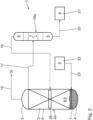
- the hydrogen release apparatus designated 1
- the hydrogen release apparatus comprises a reaction vessel 2, which, according to the illustrated embodiment, is designed as a stirred tank reactor.
- the reaction vessel 2 comprises a closed housing 3 having a bottom 4, a lid 5, and a side wall 6 connecting the bottom 4 to the lid 5.
- the reaction vessel 2 has a contacting unit 10, which, according to the illustrated embodiment, is designed as a stirrer.
- the stirrer is rotatable about a rotational axis 11, which is oriented in particular parallel to the longitudinal axis of the housing 3 and in particular parallel to the, in particular cylindrical, side wall 6 of the housing 3.
- the stirrer, with its stirring elements 12, is arranged below the level 13 of the mixture of reaction accelerator substance 8 and hydrogen carrier medium 9.
- the direction of rotation of the stirrer about the rotational axis 11 is symbolized by the arrow 14.
- the reaction vessel 2 has, in particular on the lid 5, a hydrogen discharge line 15, via which the gaseous hydrogen 16 released in the reaction vessel 2 can be supplied for further use, for example, for generating electricity in a fuel cell or for thermal utilization.
- the hydrogen discharge line 15 can also be connected to a different position on the housing 3. It is advantageous if the hydrogen discharge line 15 is arranged at a point on the housing 3 that is above the level 13.
- a liquid discharge line 17 is connected to the reaction vessel 2, which leads to a separator 18.
- the separator 18 is connected to the reaction vessel 2 via a return line 19.
- the connection for the liquid discharge line 17 on the reaction vessel 2 is provided on the bottom 4 according to the embodiment shown, in particular at a lowest point of the housing 3. This ensures a particularly advantageous removal of liquid from the reaction vessel 2.
- the liquid discharge line 17 can also be connected to the reaction vessel 2 at another point on the housing 3. It is advantageous if the connection point for the liquid discharge line 17 is arranged at a point on the housing 3 that is below the level 13.
- connection point for the return line 19 on the reaction vessel 2 is provided in particular in the area of the stirring elements 12. This improves the mixing of the returned reaction accelerator substance 8 with the liquid mixture already present in the reaction vessel 2.
- the separator 18 is further connected via a fluid line 20 to a first storage container 21 for discharged hydrogen carrier medium 9.
- a second storage tank 22 for loaded hydrogen carrier medium 9 is connected to the reaction tank 2 via a hydrogen carrier medium supply line 23.
- the hydrogen carrier medium supply line 23 is arranged on the housing 3, particularly in an area of the stirring elements 12. This improves the mixing of the supplied, loaded hydrogen carrier medium 9 with the liquid mixture present in the reaction tank 2.
- the hydrogen release apparatus 1 has a control unit 24, which is in signal communication with the individual components of the hydrogen release apparatus 1, in particular the reaction vessel 2, the separator 18, the first storage vessel 21, and the second storage vessel 22.
- the control unit 24 is connected to further Fig. 1 not shown in detail, such as heating units, pumps, and/or valves, which are arranged in particular along lines 15, 17, 19, 20, and 23, are in signal communication.
- the control unit 24 it is possible to actively control the process for releasing hydrogen gas, for example, to monitor and influence the reaction conditions in the reaction vessel 2, in particular the reaction temperature and/or reaction pressure, as well as the water level 13.
- corresponding sensors are arranged in or on the components mentioned, which are also in signal connection with the control unit 24.
- the signal connections can, as in Fig. 1 As indicated by symbol 25, the signal connections may be wireless, particularly as a radio connection. The signal connections may additionally or alternatively be wired.
- the reaction vessel 2 contains palladium from activated carbon as the metal-containing catalyst material 7, polyvinyl alcohol as the metal-free reaction accelerator substance 8, and perhydrodibenzyltoluene as the hydrogen carrier medium 9.
- the reaction accelerator substance 8 is in liquid form and, according to the illustrated embodiment, exhibits thermomorphic behavior. This means that the reaction accelerator substance 8 is at least partially dissolved in the hydrogen carrier medium 9 under the reaction conditions of 200 °C and a total pressure of less than 2 mbar in the reaction vessel 2.
- the temperature in the separator 18 is at most 50 °C. It is particularly advantageous that the reaction accelerator substance 8 has a miscibility gap with the hydrogen carrier medium 9 at a temperature of at most 50 °C.
- Fig. 1 shown schematically Two separate, mutually distinct liquid layers form independently in the separator 18, with the reaction accelerator substance 8 at the bottom and the comparatively less dense hydrogen carrier medium 9 at the top of the separator 18.
- the density of the polyvinyl alcohols is more than 1.1 g/cm 3 .
- the density of dibenzyltoluene is approximately 1.05 g/cm 3 .
- the reaction accelerator substance 8 can be easily separated from the hydrogen carrier medium 9 and can be fed to the reaction vessel 2 via the return line 19 for reuse.
- the discharged hydrogen carrier medium 9 is conveyed from the separator 18 via the fluid line 20 into the first storage vessel 21.
- the discharged hydrogen carrier medium 9 can be re-enriched with hydrogen, i.e., recharged, using a charging station.
- the charging station can be located at the location of the hydrogen release apparatus 1 or remotely therefrom.
- the charged or recharged hydrogen carrier medium 9 is stored in the second storage vessel 22 and supplied to the reaction vessel 2 via the hydrogen carrier supply line 23.
- Hydrogen 16 which in particular passes directly or in atomic form from the hydrogen carrier medium 9 to the reaction accelerator substance 8, can be released from the reaction accelerator substance 8 as hydrogen gas 16 and discharged from the reaction vessel 2 via the hydrogen discharge line 15.
- the reaction vessel 2a is designed as a bubble column reactor.
- the catalyst material 7, the liquid hydrogen carrier medium 9, and the reaction accelerator substance 8, which is present in liquid and/or gaseous form, are arranged in the reaction vessel 2a.
- the reaction accelerator substance can be 2a has a vapor pressure p R that is significantly higher than the vapor pressure p W of the hydrogen carrier medium 9.
- Acetone in particular, serves as the reaction accelerator substance 8.
- Perhydrodibenzyltoluene serves as the hydrogen carrier medium 9.
- the vapor pressure p R is around 2 mbar.
- Acetone on the other hand, is in gaseous form under these reaction conditions, in particular the reaction temperature and the total pressure.
- the bubble column reactor is a process engineering apparatus for gas/liquid processes.
- the bubble column reactor is characterized by a liquid, in this case hydrogen carrier medium 9, into which gas, in this case the reaction accelerator substance 8, is introduced and bubbles through the liquid, thereby creating a phase interface between the reaction accelerator substance 8 and the liquid hydrogen carrier medium 9.
- Gassing occurs in particular through a perforated distributor plate, an evaporator element, or an injection tube as distributor element 26, which is connected to the return line 19.
- the distributor element 26 is arranged approximately centrally on the side wall 6 between the base 4 and the cover 5.
- the hydrogen carrier medium supply line 23 is provided on the housing 3 below the connection point for the return line 19. According to the illustrated embodiment, the hydrogen carrier medium 9 and the reaction accelerator substance 8 are supplied in a cocurrent process, and the bubble column reactor is operated in a cocurrent process. It is also conceivable to carry out the process in a countercurrent process.
- a mixture of reaction accelerator substance 8 and hydrogen carrier medium 9 is removed from the reaction vessel 2a and fed to the separator 18a. Due to the significantly higher vapor pressure of the reaction accelerator substance 8 compared to the hydrogen carrier medium 9, the two substances are easily separated in the separator 18a, which is designed as an air- or water-cooled condenser.
- the condenser 18a can contain internal components to increase the surface area in the condenser 18a and thus improve the condensation effect.
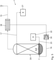
- the reaction vessel 2b is designed as a fixed-bed reactor.
- a solid is filled into the fixed-bed reactor.
- the solid is the metal-free reaction accelerator substance 8, which simultaneously serves as a porous support material for the metal-containing catalyst 7.
- This solid can provide both the function of the metal-free reaction accelerator 8 and the function of the metal-containing catalyst 7 at spatially separate locations within its structure.
- the solid metal-free reaction accelerator substance 8 is a porous sugar pyrolysis product containing alcohol functionalities, which serves as a support material for the metal-containing catalyst 7, here, for example, platinum nanoparticles.
- the reaction vessel 2b is, for example, filled with the loaded hydrogen carrier medium 9 at a temperature of 240 °C and a total pressure of 1 bar, according to the embodiment shown in Fig. 3 from bottom to top along the flow direction 27.
- the reaction accelerator substance 8 is first hydrogenated, with hydrogen in elemental form being subsequently released as a gas from the reaction accelerator substance 8 in a dehydrogenation reaction and being discharged from the reaction vessel 2b via a mixing line 28 together with evaporated hydrogen carrier medium 9.
- a condenser 29 is connected to the mixing line 28, in which the gaseous hydrogen carrier medium 9 is condensed.
- the condensed hydrogen carrier medium 9 is returned to the reaction vessel 2b via a heat exchanger 30 and the return line 19.
- Pure gaseous hydrogen 16 is discharged from the condenser 29 via the hydrogen discharge line 15.
- the at least partially discharged hydrogen carrier medium 9 leaves the reaction vessel 2b via the liquid discharge line 17 predominantly in liquid form and is fed in particular to the first storage vessel 21.
- the return line 19 and the hydrogen carrier medium supply line 23 are each located in a lower region of the reaction vessel 2b.
- the reaction accelerator substance 8 and the loaded hydrogen carrier medium 9 flow through the fixed-bed reactor together along the flow direction 27, i.e., in a cocurrent process.
- the fixed-bed reactor can also be operated in a countercurrent process.
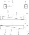
- the container 2c has a reaction-accelerating membrane 31 that separates the reaction container into a first sub-chamber 32 and a second sub-chamber 33.
- the reaction-accelerating membrane 31 is made from the solid reaction accelerator substance 8.
- the reaction accelerator substance 8 forms a structural framework of the membrane 31 and also serves as a support for the metal-containing catalyst 7 applied thereto. It is advantageous if the membrane material has a reaction-accelerating effect and possesses proton conductivity and/or selective hydrogen permeability, in particular from the first sub-chamber 32 into the second sub-chamber 33. In this way, pure hydrogen gas can be obtained on the permeate side, i.e., in the second sub-chamber 33. The released hydrogen is removed from the equilibrium by transport through the membrane 31, so that equilibrium limitations in the dehydrogenation reaction can be overcome.
- a fuel cell 34 is arranged adjacent to the reaction vessel 2c. Heat generated during the exothermic fuel cell operation can be used directly, and in particular without the use of a heat exchanger, for the operation of the reaction-accelerating membrane 31.
- a direct Heat transfer line 35 which connects the fuel cell 34 to the reaction vessel 2c, in particular to the membrane 31 arranged therein.
- a heat exchanger attached to the fuel cell 34 is used for heat transfer, which heats a heat transfer medium, in particular the hydrogen carrier medium 9, which can be used as a heat transfer medium. The heated heat transfer medium is fed to the reaction vessel 2c to heat it with the aid of a heat exchanger.
- heat transfer can be particularly advantageously achieved by locating the fuel cell 34 and the reaction vessel 2c in a thermally insulated container.
- the heat generated by the fuel cell 34 can be directly utilized for hydrogen release in the reaction vessel 2c.
- a heat pipe can be used additionally or alternatively, which connects the fuel cell, which is arranged next to each other, with the reaction vessel isothermally and particularly efficiently.
- the fuel cell 34 further comprises a supply line 36 for supplying oxygen, in particular ambient air, to the fuel cell 34.
- a power line 37 is connected to the fuel cell 34 for extracting electrical energy from the fuel cell 34.
- Another advantage is that the hydrogen consumption in the fuel cell 34 creates a steeper gradient of hydrogen concentration across the hydrogen release apparatus 1. Overall, this increases the thermodynamic driving force for hydrogen release, so that the release rate is further increased.
- the essential difference compared to the third embodiment is that in addition to the reaction vessel 2d, which is designed as a fixed bed reactor, a second reaction vessel 38 is provided.
- the hydrogen transfer from the loaded hydrogen carrier medium 9 to the reaction accelerator substance 8 takes place in the manner described.
- the enriched form of the reaction accelerator substance 8 is fed to the second reaction vessel 38, where the hydrogen release occurs. It is essential that the metal-containing catalyst 7 is contained in both the first reaction vessel 2d and the second reaction vessel 38.
- the catalysts in the reaction vessels 2d, 38 may be identical or different.
- the partial reactions are divided into different reaction vessels 2d, 38. This allows the reaction conditions to be better adapted for each partial reaction.
- the reaction temperature and reaction pressure for the hydrogen transfer from the hydrogen carrier medium 9 to the reaction accelerator substance 8, on the one hand, and for the release of hydrogen gas from the reaction accelerator substance 8 enriched in this way, on the other hand, can be selected independently of one another.
- the hydrogen transfer from the hydrogen carrier medium 9 to the reaction accelerator substance can be carried out at a reaction pressure of 1 bar and a temperature of only 180 °C.
- the hydrogen gas release from the reaction accelerator substance 8 can be carried out, for example, at 240 °C and a total pressure of 5 bar.
- Pure hydrogen gas 16 is generated by condensing the hydrogen-depleted reaction accelerator substance 8 in the second reaction vessel 38.
- the condensed reaction accelerator substance is returned as a liquid via the return line 19 to the first reaction vessel 2d.
- the autoclave contains 0.265 g of Pd, which corresponds to a quantity of 0.25 mol% based on the perhydrodibenzyltoluene used.
- the autoclave also contains equimolar amounts of perhydrodibenzyltoluene and acetone.
- the autoclave is heated to 210 °C and maintained at this temperature with stirring for five hours.
- the autoclave is then cooled back to room temperature, and the autoclave pressure is determined at room temperature.
- the autoclave is then depressurized, opened, and a liquid sample is taken. It is found that a significant amount of hydrogen gas has been formed.
- the pressure in the autoclave after complete cooling to room temperature was over 16 bar.
- Gas chromatographic analysis of the gas phase revealed that the gas phase consists exclusively of hydrogen.
- the liquid sample revealed a decrease in the degree of hydrogenation of the hydrogen carrier medium of more than 10%, i.e., to less than 90%.
Landscapes
- Chemical & Material Sciences (AREA)
- Organic Chemistry (AREA)
- Chemical Kinetics & Catalysis (AREA)
- Engineering & Computer Science (AREA)
- Materials Engineering (AREA)
- Health & Medical Sciences (AREA)
- General Health & Medical Sciences (AREA)
- Combustion & Propulsion (AREA)
- Inorganic Chemistry (AREA)
- Catalysts (AREA)
- Hydrogen, Water And Hydrids (AREA)
Claims (13)
- Procédé de déshydrogénation d'un milieu porteur d'hydrogène comprenant les étapes de procédé- préparation-- d'un matériau catalytique (7) contenant un métal,-- d'un milieu porteur d'hydrogène (9) au moins partiellement chargé (9),-- d'une substance accélératrice de réaction (8) exempte de métal,- transfert d'hydrogène à partir du milieu porteur d'hydrogène (9) sur la substance accélératrice de réaction (8) au moyen du matériau catalytique (7) contenant un métal,- libération de l'hydrogène gazeux (16) à partir de la substance accélératrice de réaction (8) au moyen du matériau catalytique (7) contenant un métal,dans lequel la substance accélératrice de réaction (8) présente au moins un groupement fonctionnel qui contient de l'oxygène et/ou de l'azote.
- Procédé selon la revendication 1, caractérisé par une pression de réaction (p) de 0,001 bar à 50 bar, en particulier de 0,3 bar à 20 bar, en particulier de 0,8 bar à 3 bar et en particulier inférieure à 0,1 bar.
- Procédé selon l'une des revendications précédentes, caractérisé par une température de réaction (T) de 25 °C à 400 °C, en particulier de 60 °C à 250 °C, en particulier de 80 °C à 220 °C et en particulier inférieure à 100 °C.
- Procédé selon l'une des revendications précédentes, caractérisé par un taux de libération d'au moins 10 normo litres d'hydrogène par litre, volume de catalyseur et minute pour une température de réaction (T) inférieure à 250 °C.
- Procédé selon l'une des revendications précédentes, caractérisé en ce que la substance accélératrice de réaction (8) dans la forme enrichie en hydrogène comprend des alcools secondaires
selon
- Procédé selon l'une des revendications précédentes, caractérisé en ce que la substance accélératrice de réaction (8) dans la forme enrichie en hydrogène comprend des alcools oligovinyliques
selon

- Procédé selon l'une des revendications précédentes, caractérisé en ce que la substance accélératrice de réaction (8) dans la forme enrichie en hydrogène comprend des amines secondaires
selon
- Procédé selon l'une des revendications précédentes, caractérisé en ce que la substance accélératrice de réaction (8) dans la forme enrichie en hydrogène comprend des oligovinylamines et/ou des polyvinylamines
selon
- Procédé selon l'une des revendications précédentes, caractérisé en ce que la substance accélératrice de réaction (8) dans la forme enrichie en hydrogène comprend un composé hétéro alicyclique déshydrogénable selon



- Procédé selon l'une des revendications précédentes, caractérisé en ce que la substance accélératrice de réaction (8) présente une pression de vapeur (pR) qui est supérieure à la pression de vapeur (pW) du milieu porteur d'hydrogène (9), où, en particulier pR > 1,5 · pw, en particulier pR > 2,0 · pw, en particulier PR > 5,0 · pw, en particulier pR > 10,0 · pw.
- Procédé selon l'une des revendications 1 à 9, caractérisé en ce que la substance accélératrice de réaction (8) présente une pression de vapeur (PR) qui est inférieure à la pression de vapeur (pW) du milieu porteur d'hydrogènes (9), où, en particulier pR < 0,8 · pw, en particulier PR < 0,6 · pw, en particulier pR < 0,3 · pw, en particulier pR < 0,1 · pw.
- Procédé selon l'une des revendications précédentes, caractérisé en ce que la substance accélératrice de réaction (8), pour une température d'au maximum 50 °C, présente une lacune de miscibilité avec le milieu porteur d'hydrogène (9).
- Procédé selon l'une des revendications précédentes, caractérisé en ce que la substance accélératrice de réaction (8) est présente sous forme solide, dans lequel le matériau catalytique (7) est en particulier directement séparé sur la substance accélératrice de réaction (8).
Applications Claiming Priority (3)
| Application Number | Priority Date | Filing Date | Title |
|---|---|---|---|
| DE102018210247 | 2018-06-22 | ||
| DE102018210337.2A DE102018210337A1 (de) | 2018-06-22 | 2018-06-25 | Verfahren und Vorrichtung zum Dehydrieren eines Wasserstoffträgermediums |
| PCT/EP2019/064819 WO2019243073A1 (fr) | 2018-06-22 | 2019-06-06 | Procédé et dispositif de déshydrogénation d'un milieu porteur d'hydrogène |
Publications (2)
| Publication Number | Publication Date |
|---|---|
| EP3810545A1 EP3810545A1 (fr) | 2021-04-28 |
| EP3810545B1 true EP3810545B1 (fr) | 2025-05-14 |
Family
ID=68805928
Family Applications (1)
| Application Number | Title | Priority Date | Filing Date |
|---|---|---|---|
| EP19729273.3A Active EP3810545B1 (fr) | 2018-06-22 | 2019-06-06 | Procédé de déshydrogénation d'un milieu porteur d'hydrogène |
Country Status (4)
| Country | Link |
|---|---|
| US (1) | US11383974B2 (fr) |
| EP (1) | EP3810545B1 (fr) |
| DE (1) | DE102018210337A1 (fr) |
| WO (1) | WO2019243073A1 (fr) |
Families Citing this family (6)
| Publication number | Priority date | Publication date | Assignee | Title |
|---|---|---|---|---|
| US20220380691A1 (en) * | 2020-10-06 | 2022-12-01 | The Claire Technologies Corporation | Heat integration for generating carbon-neutral electricity |
| CN112871091A (zh) * | 2021-01-08 | 2021-06-01 | 西安交通大学 | 一种新型lohc加氢系统及方法 |
| DE102021203885A1 (de) * | 2021-04-19 | 2022-10-20 | Hydrogenious Lohc Technologies Gmbh | Verfahren und Anlage zum Bereitstellen von Wasserstoffgas |
| DE102021203886A1 (de) * | 2021-04-19 | 2022-10-20 | Hydrogenious Lohc Technologies Gmbh | Verfahren, Verwendung eines Indikatormaterials und Anlage zum Bestimmen eines Zustands eines Wasserstoffträgermaterials |
| KR20230135832A (ko) * | 2022-03-17 | 2023-09-26 | 현대자동차주식회사 | 탈수소화 반응 장치 및 이를 포함하는 시스템 |
| IT202300020679A1 (it) * | 2023-10-05 | 2025-04-05 | Serichim S R L | Dispensatore dinamico di idrogeno da lohc |
Family Cites Families (12)
| Publication number | Priority date | Publication date | Assignee | Title |
|---|---|---|---|---|
| DE10055717A1 (de) * | 2000-11-10 | 2002-05-29 | Jens Burfeind | Verfahren zum Transport und zur Lagerung von Wasserstoff in chemisch fixierter Form |
| JP2004082007A (ja) * | 2002-08-27 | 2004-03-18 | Honda Motor Co Ltd | 触媒粒子及びアルコールの脱水素触媒粒子 |
| US7101530B2 (en) | 2003-05-06 | 2006-09-05 | Air Products And Chemicals, Inc. | Hydrogen storage by reversible hydrogenation of pi-conjugated substrates |
| US7601329B2 (en) * | 2004-02-26 | 2009-10-13 | Gm Global Technology Operations, Inc. | Regeneration of hydrogen storage system materials and methods including hydrides and hydroxides |
| US8338055B2 (en) * | 2007-04-04 | 2012-12-25 | General Electric Company | System and method for electrochemical energy conversion and storage |
| US10328412B2 (en) * | 2010-02-17 | 2019-06-25 | Asemblon Inc. | Hydrogen storage system by catalytic dehydrogenation of amines |
| US9174843B2 (en) * | 2012-07-16 | 2015-11-03 | Intelligent Energy Inc. | Valve having concentric fluid paths |
| CN105324875A (zh) * | 2013-06-07 | 2016-02-10 | 通用电气公司 | 能在电化学反应中操作的阴极和相关的电池、装置以及方法 |
| JP2015030653A (ja) | 2013-08-06 | 2015-02-16 | 千代田化工建設株式会社 | エネルギー利用システムおよびエネルギー利用方法 |
| DE102014201332A1 (de) * | 2014-01-24 | 2015-07-30 | Hydrogenious Technologies Gmbh | System und Verfahren zur stofflichen Nutzung von Wasserstoff |
| JP6244214B2 (ja) | 2014-02-03 | 2017-12-06 | 千代田化工建設株式会社 | 芳香族化合物の水素化システム及びこれを備えた水素貯蔵・輸送システム並びに芳香族化合物の水素化方法 |
| KR101845515B1 (ko) | 2016-09-30 | 2018-04-04 | 한국과학기술연구원 | 액상 수소저장물질 및 이를 이용한 수소 저장 방법 |
-
2018
- 2018-06-25 DE DE102018210337.2A patent/DE102018210337A1/de not_active Ceased
-
2019
- 2019-06-06 EP EP19729273.3A patent/EP3810545B1/fr active Active
- 2019-06-06 US US17/254,772 patent/US11383974B2/en active Active
- 2019-06-06 WO PCT/EP2019/064819 patent/WO2019243073A1/fr not_active Ceased
Also Published As
| Publication number | Publication date |
|---|---|
| DE102018210337A1 (de) | 2019-12-24 |
| WO2019243073A1 (fr) | 2019-12-26 |
| US11383974B2 (en) | 2022-07-12 |
| EP3810545A1 (fr) | 2021-04-28 |
| US20210276862A1 (en) | 2021-09-09 |
Similar Documents
| Publication | Publication Date | Title |
|---|---|---|
| EP3810545B1 (fr) | Procédé de déshydrogénation d'un milieu porteur d'hydrogène | |
| Stoffels et al. | Technology trends of catalysts in hydrogenation reactions: A patent landscape analysis | |
| EP2925669B1 (fr) | Utilisation des composés liquides et procédé d'utilisation comme accumulateurs d'hydrogène | |
| EP2417058B1 (fr) | Procédé de séparation électrochimique d'hydrogène présent dans un mélange de réaction | |
| EP2417059B1 (fr) | Procédé de transformation de gaz naturel en hydrocarbures aromatiques, avec séparation électrochimique d'hydrogène | |
| EP3034485B1 (fr) | Réaction du dioxide de carbone avec hydrogène utilisant une membrane permsélective | |
| DE102018213689A1 (de) | Vorrichtung und Verfahren zum Bereitstellen von Wasserstoffgas | |
| CH687004A5 (de) | Membranreaktor fuer die Umsetzung von gasfoermigen Ausgangsstoffen. | |
| WO2018054740A1 (fr) | Procédé de préparation d'un lit fixe de catalyseur comprenant des corps moulés de catalyseur structurés dopés | |
| EP3894351A1 (fr) | Procede et installation pour libérer un gaz d'un milieu liquide | |
| WO2022223443A1 (fr) | Procédé et système de fourniture d'hydrogène gazeux purifié | |
| DE102011079858A1 (de) | Reaktor zur Freisetzung von Wasserstoff aus flüssigen Verbindungen | |
| WO2011023368A1 (fr) | Composition catalytique pour la mise en réaction de monoxyde de carbone dans des flux gazeux | |
| DE2055539A1 (de) | Verfahren zur Hydroformylierung oder Carbonylierung einer organischen Verbin dung | |
| EP4326668A1 (fr) | Procédé, utilisation d'un matériau indicateur et appareil pour déterminer un état d'un matériau de support d'hydrogène | |
| EP2739386B1 (fr) | Procédé de déshydrogénation catalytique autothermique en phase gazeuse fonctionnant en mode de production et de régénération | |
| DE102022210591A1 (de) | Verfahren und Vorrichtung zum Bereitstellen und/oder Speichern von Wasserstoffgas | |
| DE10046692A1 (de) | Vorrichtung zur Verdampfung einer Flüssigkeit | |
| DE4303610A1 (de) | Verfahren zur Herstellung von vergiftungsfesten Katalysatoren | |
| CN1695802A (zh) | 一种铜锌系气相醛加氢制醇催化剂及其制备方法 | |
| DE102005001290A1 (de) | Vorrichtung und Verfahren zur Entfernung von Kohlenmonoxid aus einem wasserstoffhaltigen Gasstrom | |
| DE102018003332A1 (de) | Herstellung eines Syntheseprodukts | |
| DE102015201560A1 (de) | SILP-Katalysator zur Hydroformylierung von Olefinen mit Synthesegas | |
| EP4477645A1 (fr) | Procédé d'alcoxycarbonylation de di-isobutène par distillation préalable | |
| WO2025247447A1 (fr) | Procédé de déshydrogénation d'un matériau support d'hydrogène liquide |
Legal Events
| Date | Code | Title | Description |
|---|---|---|---|
| STAA | Information on the status of an ep patent application or granted ep patent |
Free format text: STATUS: UNKNOWN |
|
| STAA | Information on the status of an ep patent application or granted ep patent |
Free format text: STATUS: THE INTERNATIONAL PUBLICATION HAS BEEN MADE |
|
| PUAI | Public reference made under article 153(3) epc to a published international application that has entered the european phase |
Free format text: ORIGINAL CODE: 0009012 |
|
| STAA | Information on the status of an ep patent application or granted ep patent |
Free format text: STATUS: REQUEST FOR EXAMINATION WAS MADE |
|
| 17P | Request for examination filed |
Effective date: 20201210 |
|
| AK | Designated contracting states |
Kind code of ref document: A1 Designated state(s): AL AT BE BG CH CY CZ DE DK EE ES FI FR GB GR HR HU IE IS IT LI LT LU LV MC MK MT NL NO PL PT RO RS SE SI SK SM TR |
|
| AX | Request for extension of the european patent |
Extension state: BA ME |
|
| DAV | Request for validation of the european patent (deleted) | ||
| DAX | Request for extension of the european patent (deleted) | ||
| STAA | Information on the status of an ep patent application or granted ep patent |
Free format text: STATUS: EXAMINATION IS IN PROGRESS |
|
| 17Q | First examination report despatched |
Effective date: 20221125 |
|
| P01 | Opt-out of the competence of the unified patent court (upc) registered |
Effective date: 20230519 |
|
| GRAP | Despatch of communication of intention to grant a patent |
Free format text: ORIGINAL CODE: EPIDOSNIGR1 |
|
| STAA | Information on the status of an ep patent application or granted ep patent |
Free format text: STATUS: GRANT OF PATENT IS INTENDED |
|
| INTG | Intention to grant announced |
Effective date: 20250128 |
|
| GRAS | Grant fee paid |
Free format text: ORIGINAL CODE: EPIDOSNIGR3 |
|
| GRAA | (expected) grant |
Free format text: ORIGINAL CODE: 0009210 |
|
| STAA | Information on the status of an ep patent application or granted ep patent |
Free format text: STATUS: THE PATENT HAS BEEN GRANTED |
|
| AK | Designated contracting states |
Kind code of ref document: B1 Designated state(s): AL AT BE BG CH CY CZ DE DK EE ES FI FR GB GR HR HU IE IS IT LI LT LU LV MC MK MT NL NO PL PT RO RS SE SI SK SM TR |
|
| REG | Reference to a national code |
Ref country code: GB Ref legal event code: FG4D Free format text: NOT ENGLISH |
|
| REG | Reference to a national code |
Ref country code: CH Ref legal event code: EP |
|
| REG | Reference to a national code |
Ref country code: DE Ref legal event code: R096 Ref document number: 502019013348 Country of ref document: DE |
|
| REG | Reference to a national code |
Ref country code: IE Ref legal event code: FG4D Free format text: LANGUAGE OF EP DOCUMENT: GERMAN |
|
| REG | Reference to a national code |
Ref country code: NL Ref legal event code: MP Effective date: 20250514 |
|
| PG25 | Lapsed in a contracting state [announced via postgrant information from national office to epo] |
Ref country code: PT Free format text: LAPSE BECAUSE OF FAILURE TO SUBMIT A TRANSLATION OF THE DESCRIPTION OR TO PAY THE FEE WITHIN THE PRESCRIBED TIME-LIMIT Effective date: 20250915 Ref country code: FI Free format text: LAPSE BECAUSE OF FAILURE TO SUBMIT A TRANSLATION OF THE DESCRIPTION OR TO PAY THE FEE WITHIN THE PRESCRIBED TIME-LIMIT Effective date: 20250514 Ref country code: ES Free format text: LAPSE BECAUSE OF FAILURE TO SUBMIT A TRANSLATION OF THE DESCRIPTION OR TO PAY THE FEE WITHIN THE PRESCRIBED TIME-LIMIT Effective date: 20250514 |
|
| PGFP | Annual fee paid to national office [announced via postgrant information from national office to epo] |
Ref country code: DE Payment date: 20250815 Year of fee payment: 7 |
|
| REG | Reference to a national code |
Ref country code: LT Ref legal event code: MG9D |
|
| PG25 | Lapsed in a contracting state [announced via postgrant information from national office to epo] |
Ref country code: NO Free format text: LAPSE BECAUSE OF FAILURE TO SUBMIT A TRANSLATION OF THE DESCRIPTION OR TO PAY THE FEE WITHIN THE PRESCRIBED TIME-LIMIT Effective date: 20250814 Ref country code: GR Free format text: LAPSE BECAUSE OF FAILURE TO SUBMIT A TRANSLATION OF THE DESCRIPTION OR TO PAY THE FEE WITHIN THE PRESCRIBED TIME-LIMIT Effective date: 20250815 |
|
| PG25 | Lapsed in a contracting state [announced via postgrant information from national office to epo] |
Ref country code: PL Free format text: LAPSE BECAUSE OF FAILURE TO SUBMIT A TRANSLATION OF THE DESCRIPTION OR TO PAY THE FEE WITHIN THE PRESCRIBED TIME-LIMIT Effective date: 20250514 Ref country code: NL Free format text: LAPSE BECAUSE OF FAILURE TO SUBMIT A TRANSLATION OF THE DESCRIPTION OR TO PAY THE FEE WITHIN THE PRESCRIBED TIME-LIMIT Effective date: 20250514 |
|
| PG25 | Lapsed in a contracting state [announced via postgrant information from national office to epo] |
Ref country code: BG Free format text: LAPSE BECAUSE OF FAILURE TO SUBMIT A TRANSLATION OF THE DESCRIPTION OR TO PAY THE FEE WITHIN THE PRESCRIBED TIME-LIMIT Effective date: 20250514 |
|
| PG25 | Lapsed in a contracting state [announced via postgrant information from national office to epo] |
Ref country code: HR Free format text: LAPSE BECAUSE OF FAILURE TO SUBMIT A TRANSLATION OF THE DESCRIPTION OR TO PAY THE FEE WITHIN THE PRESCRIBED TIME-LIMIT Effective date: 20250514 |
|
| PG25 | Lapsed in a contracting state [announced via postgrant information from national office to epo] |
Ref country code: RS Free format text: LAPSE BECAUSE OF FAILURE TO SUBMIT A TRANSLATION OF THE DESCRIPTION OR TO PAY THE FEE WITHIN THE PRESCRIBED TIME-LIMIT Effective date: 20250814 |
|
| PG25 | Lapsed in a contracting state [announced via postgrant information from national office to epo] |
Ref country code: IS Free format text: LAPSE BECAUSE OF FAILURE TO SUBMIT A TRANSLATION OF THE DESCRIPTION OR TO PAY THE FEE WITHIN THE PRESCRIBED TIME-LIMIT Effective date: 20250914 |
|
| PG25 | Lapsed in a contracting state [announced via postgrant information from national office to epo] |
Ref country code: LV Free format text: LAPSE BECAUSE OF FAILURE TO SUBMIT A TRANSLATION OF THE DESCRIPTION OR TO PAY THE FEE WITHIN THE PRESCRIBED TIME-LIMIT Effective date: 20250514 |
|
| PG25 | Lapsed in a contracting state [announced via postgrant information from national office to epo] |
Ref country code: DK Free format text: LAPSE BECAUSE OF FAILURE TO SUBMIT A TRANSLATION OF THE DESCRIPTION OR TO PAY THE FEE WITHIN THE PRESCRIBED TIME-LIMIT Effective date: 20250514 Ref country code: SM Free format text: LAPSE BECAUSE OF FAILURE TO SUBMIT A TRANSLATION OF THE DESCRIPTION OR TO PAY THE FEE WITHIN THE PRESCRIBED TIME-LIMIT Effective date: 20250514 |
|
| PG25 | Lapsed in a contracting state [announced via postgrant information from national office to epo] |
Ref country code: CZ Free format text: LAPSE BECAUSE OF FAILURE TO SUBMIT A TRANSLATION OF THE DESCRIPTION OR TO PAY THE FEE WITHIN THE PRESCRIBED TIME-LIMIT Effective date: 20250514 |
|
| PG25 | Lapsed in a contracting state [announced via postgrant information from national office to epo] |
Ref country code: EE Free format text: LAPSE BECAUSE OF FAILURE TO SUBMIT A TRANSLATION OF THE DESCRIPTION OR TO PAY THE FEE WITHIN THE PRESCRIBED TIME-LIMIT Effective date: 20250514 |
|
| PG25 | Lapsed in a contracting state [announced via postgrant information from national office to epo] |
Ref country code: RO Free format text: LAPSE BECAUSE OF FAILURE TO SUBMIT A TRANSLATION OF THE DESCRIPTION OR TO PAY THE FEE WITHIN THE PRESCRIBED TIME-LIMIT Effective date: 20250514 Ref country code: SK Free format text: LAPSE BECAUSE OF FAILURE TO SUBMIT A TRANSLATION OF THE DESCRIPTION OR TO PAY THE FEE WITHIN THE PRESCRIBED TIME-LIMIT Effective date: 20250514 |
|
| REG | Reference to a national code |
Ref country code: CH Ref legal event code: H13 Free format text: ST27 STATUS EVENT CODE: U-0-0-H10-H13 (AS PROVIDED BY THE NATIONAL OFFICE) Effective date: 20260127 |
|
| PG25 | Lapsed in a contracting state [announced via postgrant information from national office to epo] |
Ref country code: IT Free format text: LAPSE BECAUSE OF FAILURE TO SUBMIT A TRANSLATION OF THE DESCRIPTION OR TO PAY THE FEE WITHIN THE PRESCRIBED TIME-LIMIT Effective date: 20250514 |
|
| PG25 | Lapsed in a contracting state [announced via postgrant information from national office to epo] |
Ref country code: LU Free format text: LAPSE BECAUSE OF NON-PAYMENT OF DUE FEES Effective date: 20250606 |
|
| REG | Reference to a national code |
Ref country code: DE Ref legal event code: R097 Ref document number: 502019013348 Country of ref document: DE |
|
| PG25 | Lapsed in a contracting state [announced via postgrant information from national office to epo] |
Ref country code: MC Free format text: LAPSE BECAUSE OF FAILURE TO SUBMIT A TRANSLATION OF THE DESCRIPTION OR TO PAY THE FEE WITHIN THE PRESCRIBED TIME-LIMIT Effective date: 20250514 |
|
| REG | Reference to a national code |
Ref country code: BE Ref legal event code: MM Effective date: 20250630 |
|
| PLBE | No opposition filed within time limit |
Free format text: ORIGINAL CODE: 0009261 |
|
| STAA | Information on the status of an ep patent application or granted ep patent |
Free format text: STATUS: NO OPPOSITION FILED WITHIN TIME LIMIT |
|
| REG | Reference to a national code |
Ref country code: CH Ref legal event code: L10 Free format text: ST27 STATUS EVENT CODE: U-0-0-L10-L00 (AS PROVIDED BY THE NATIONAL OFFICE) Effective date: 20260325 |
|
| PG25 | Lapsed in a contracting state [announced via postgrant information from national office to epo] |
Ref country code: IE Free format text: LAPSE BECAUSE OF NON-PAYMENT OF DUE FEES Effective date: 20250606 |
|
| PG25 | Lapsed in a contracting state [announced via postgrant information from national office to epo] |
Ref country code: BE Free format text: LAPSE BECAUSE OF NON-PAYMENT OF DUE FEES Effective date: 20250630 |
|
| PG25 | Lapsed in a contracting state [announced via postgrant information from national office to epo] |
Ref country code: FR Free format text: LAPSE BECAUSE OF NON-PAYMENT OF DUE FEES Effective date: 20250714 |
|
| 26N | No opposition filed |
Effective date: 20260217 |
|
| PG25 | Lapsed in a contracting state [announced via postgrant information from national office to epo] |
Ref country code: CH Free format text: LAPSE BECAUSE OF NON-PAYMENT OF DUE FEES Effective date: 20250630 |